EP2134995B1 - Vanne à garniture mécanique et ensemble correspondant - Google Patents
Vanne à garniture mécanique et ensemble correspondant Download PDFInfo
- Publication number
- EP2134995B1 EP2134995B1 EP08788183.5A EP08788183A EP2134995B1 EP 2134995 B1 EP2134995 B1 EP 2134995B1 EP 08788183 A EP08788183 A EP 08788183A EP 2134995 B1 EP2134995 B1 EP 2134995B1
- Authority
- EP
- European Patent Office
- Prior art keywords
- assembly according
- base body
- sealing ring
- actuation shaft
- sealing
- Prior art date
- Legal status (The legal status is an assumption and is not a legal conclusion. Google has not performed a legal analysis and makes no representation as to the accuracy of the status listed.)
- Active
Links
Images


Classifications
-
- F—MECHANICAL ENGINEERING; LIGHTING; HEATING; WEAPONS; BLASTING
- F16—ENGINEERING ELEMENTS AND UNITS; GENERAL MEASURES FOR PRODUCING AND MAINTAINING EFFECTIVE FUNCTIONING OF MACHINES OR INSTALLATIONS; THERMAL INSULATION IN GENERAL
- F16K—VALVES; TAPS; COCKS; ACTUATING-FLOATS; DEVICES FOR VENTING OR AERATING
- F16K41/00—Spindle sealings
- F16K41/10—Spindle sealings with diaphragm, e.g. shaped as bellows or tube
- F16K41/106—Spindle sealings with diaphragm, e.g. shaped as bellows or tube for use with rotating spindles or valves
-
- F—MECHANICAL ENGINEERING; LIGHTING; HEATING; WEAPONS; BLASTING
- F16—ENGINEERING ELEMENTS AND UNITS; GENERAL MEASURES FOR PRODUCING AND MAINTAINING EFFECTIVE FUNCTIONING OF MACHINES OR INSTALLATIONS; THERMAL INSULATION IN GENERAL
- F16J—PISTONS; CYLINDERS; SEALINGS
- F16J15/00—Sealings
- F16J15/16—Sealings between relatively-moving surfaces
- F16J15/34—Sealings between relatively-moving surfaces with slip-ring pressed against a more or less radial face on one member
- F16J15/36—Sealings between relatively-moving surfaces with slip-ring pressed against a more or less radial face on one member connected by a diaphragm or bellow to the other member
- F16J15/363—Sealings between relatively-moving surfaces with slip-ring pressed against a more or less radial face on one member connected by a diaphragm or bellow to the other member the diaphragm or bellow being made of metal
Definitions
- the present invention relates to an assembly according to claim 1.
- Simple valves are known from JP 60 188 677 , tandems of valves FR2451526 .
- Butterfly valves are known in the state of the art comprising a base body delimiting a section of the flow of a fluid and a shutter member adapted to close the flow section.
- the shutter member is housed in rotation about an axis by means of an actuating shaft.
- valves are for example used in nuclear power plants in the inlet ducts of turbines.
- the seal between the actuating shaft and the base body is usually provided by a braided packing which is compressed using a follower and a stuffing box flange.
- the object of the invention is to provide a valve having a short reaction time for a given actuation torque.
- the subject of the invention is an assembly having the characteristics of claim 1.
- the assembly according to the invention comprises the characteristics of the dependent claims.
- the assembly 2 comprises two valves 4 and 6.
- the two valves 4 and 6 are identical and are arranged with respect to each other offset by 180 ° around an axis extending perpendicular to the plane of the Figure 1 .
- the assembly 2 is also provided with a base plate 8 on which the two valves 4 and 6 are fixed.
- the assembly 2 is intended to be installed, for example, in a nuclear power station in a steam turbine inlet duct and is used to isolate and quickly close the inlet duct.
- the valves 4 and 6 are intended to operate at high temperatures, for example of the order of 300 ° C., and also at high pressures, for example of the order of 16 bars.
- the valve 4 is a butterfly valve which comprises a base body 10, a shutter member 12, an actuator shaft 14, a mechanical seal 16, a needle bearing 18 and an actuator 20.
- the base body 10 defines a flow section 22, of circular cross section, through which the pressurized fluid passes during operation.
- the flow section 22 extends along a Y-Y axis and the two flow sections 22 of the valves 4 and 6 are aligned such that their Y-Y axes coincide.
- the shutter member 12 is constituted by a domed disc having a circular shape adapted to the cross section of the flow section.
- the shutter member 12 is fixed to the actuating shaft 14.
- the actuating shaft 14, and consequently the shutter member 12 is movable in rotation about an axis of rotation X-X.
- the expressions “axially” and “in rotation” will be used with respect to the axis of rotation X-X.
- the shutter member 12 and the actuating shaft 14 are movable between a passage position in which the fluid can flow through the flow section 22 and a closed position in which the shutter member 12 completely closes the valve. flow section 22.
- the actuator shaft 14 is rotatably supported relative to the base body 10 by means of the needle bearing 18.
- the needle bearing may be replaced by a bearing having non-needle bearing bodies.
- the actuating shaft 14 can be moved from its passage and closed positions by means of the actuating device 20.
- This actuating device 20 comprises, for example, a hydraulic cylinder 25 whose piston is connected to the shaft. actuation.
- the mechanical seal 16 is inserted between the actuator shaft 14 and a housing 28 provided in the base body 10.
- the mechanical seal 16 is shown in more detail on the Figure 3 .
- the mechanical seal 16 comprises a rotary assembly 30 fixed axially and in rotation to the actuating shaft 14 as well as a fixed assembly in rotation 32 fixed to the base body 10.
- the rotary assembly 30 is provided with a first sealing ring 34, a sleeve 36, a clamping flange 38 and a counter flange 40.
- the fixed rotating assembly 32 comprises a second sealing ring 42, a ring carrier 44, a bellows 46 and a support 48.
- the fixed rotating assembly 32 extends axially between the first sealing ring 34 and the clamp 38.
- the first sealing ring 34 is provided with a first annular sealing surface 50 directed towards the second sealing ring 42, and the second sealing ring 42 has a second annular sealing surface 52 directed towards the first. sealing ring.
- the second sealing surface 52 is applied to the first sealing surface 50.
- the first sealing ring 34 is fixed to the sleeve 36 and a seal 35 is interposed between these two elements 34 and 36.
- the clamping flange 38 and the counter flange 40 are fixed by mutual axial clamping to the sleeve. 36 and compress a seal 39 disposed between the sleeve 36 and the actuating shaft 14.
- the second sealing ring 42 and the ring carrier 44 are fixed in rotation relative to the base body 10 but are axially movable relative to the latter.
- the bellows 46 resiliently urges the ring holder 44 and the second sealing ring 42 against the first sealing ring 34 in the axial direction.
- the bellows 46 is preferably made of metal and is closed in the circumferential direction about the X-X axis.
- reaction time of the valve for a given actuating torque is substantially identical over a wide temperature range thanks to the use of an elastic element, such as bellows 46.
- a bearing 18 with a rolling body makes it possible to limit the friction between the shaft 14 and the base body 10 and contributes to the reactivity of the valve according to the invention.
- the bellows 46 can be replaced by any spring means, for example coil springs.
- the mechanical seal 16 can be used with any valve having a shutter other than a disc, for example a spherical shutter.
Description
- La présente invention concerne un ensemble selon la revendication 1. Des vannes simples sont connues de
JP 60 188 677 FR2451526 - On connaît dans l'état de la technique des vannes papillon comprenant un corps de base délimitant un tronçon d'écoulement d'un fluide et un organe obturateur adapté pour obturer le tronçon d'écoulement. L'organe obturateur est logé en rotation autour d'un axe au moyen d'un arbre d'actionnement.
- De telles vannes sont par exemple utilisées dans des centrales nucléaires dans les conduits d'admission de turbines.
- L'étanchéité entre l'arbre d'actionnement et le corps de base est habituellement assurée par une garniture tressée qui est comprimée à l'aide d'un fouloir et d'une bride de presse étoupe.
- Les vannes papillon connues conduisent à un temps de réaction important pour un couple d'actionnement donné.
- L'invention a pour but de fournir une vanne ayant un temps de réaction court pour un couple d'actionnement donné.
- A cet effet, l'invention a pour objet un ensemble ayant les caractéristiques de la revendication 1.
- Selon des modes de réalisation particuliers, l'ensemble selon l'invention comprend les caractéristiques des revendications dépendantes.
- L'invention sera mieux comprise à la lecture de la description qui va suivre, donnée uniquement à titre d'exemple et faite en se référant aux dessins annexés, sur lesquels :
- la
Figure 1 montre une vue de dessus d'un ensemble de deux vannes selon l'invention ; - la
Figure 2 montre une vue en perspective et partiellement coupée d'une partie du dispositif de l'invention. et - la
Figure 3 montre un détail de laFigure 2 à plus grande échelle. - Sur la
Figure 1 est montré en plan un ensemble de deux vannes, désigné par la référence générale 2. L'ensemble 2 comporte deux vannes 4 et 6. Les deux vannes 4 et 6 sont identiques et sont disposées l'une par rapport à l'autre décalées de 180° autour d'un axe s'étendant perpendiculairement au plan de laFigure 1 . L'ensemble 2 est en outre muni d'une plaque de base 8 sur laquelle sont fixées les deux vannes 4 et 6. - L'ensemble 2 est destiné à être installé par exemple dans une centrale nucléaire dans un conduit d'admission de turbine vapeur et sert à faire l'isolement et la régulation à fermeture rapide du conduit d'admission. Les vannes 4 et 6 sont destinées à fonctionner à des températures élevées, par exemple de l'ordre de 300° C, et à des pressions également élevées, par exemple de l'ordre de 16 bars.
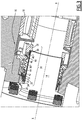
- Sur la
Figure 2 est représentée en perspective la vanne 4. La vanne 4 est une vanne à papillon qui comprend un corps de base 10, un organe obturateur 12, un arbre d'actionnement 14, une garniture mécanique 16, un roulement à aiguilles 18 et un dispositif d'actionnement 20. - Le corps de base 10 définit un tronçon d'écoulement 22, de section transversale circulaire, qui est traversé par le fluide sous pression lors du fonctionnement. Le tronçon d'écoulement 22 s'étend suivant un axe Y-Y et les deux tronçons d'écoulement 22 des vannes 4 et 6 sont alignés de telle sorte que leurs axes Y-Y coïncident.
- L'organe obturateur 12 est constitué par un disque bombé ayant une forme circulaire adaptée à la section transversale du tronçon d'écoulement. L'organe obturateur 12 est fixé à l'arbre d'actionnement 14.
- L'arbre d'actionnement 14, et en conséquence l'organe obturateur 12, est mobile en rotation autour d'un axe de rotation X-X. Dans ce qui suit, les expressions « axialement » et « en rotation » seront utilisées par rapport à l'axe de rotation X-X. L'organe obturateur 12 et l'arbre d'actionnement 14 sont mobiles entre une position de passage dans laquelle le fluide peut circuler à travers le tronçon d'écoulement 22 et une position d'obturation dans laquelle l'organe obturateur 12 ferme complètement le tronçon d'écoulement 22.
- L'arbre d'actionnement 14 est supporté en rotation par rapport au corps de base 10 au moyen du roulement à aiguilles 18. En variante, le roulement à aiguilles peut être remplacé par un roulement ayant des corps de roulement autre que des aiguilles.
- L'arbre d'actionnement 14 peut être déplacé de ses positions de passage et d'obturation au moyen du dispositif d'actionnement 20. Ce dispositif d'actionnement 20 comporte par exemple un vérin hydraulique 25 dont le piston est relié à l'arbre d'actionnement.
- Afin d'assurer l'étanchéité entre le tronçon d'écoulement 22 et l'espace extérieur, notamment vis-à-vis du dispositif d'actionnement 20, la garniture mécanique 16 est insérée entre l'arbre d'actionnement 14 et un logement 28 ménagé dans le corps de base 10.
- La garniture mécanique 16 est représentée plus en détail sur la
Figure 3 . - La garniture mécanique 16 comporte un ensemble rotatif 30 fixé axialement et en rotation à l'arbre d'actionnement 14 ainsi qu'un ensemble fixe en rotation 32 fixé au corps de base 10.
- L'ensemble rotatif 30 est muni d'un premier anneau d'étanchéité 34, d'un manchon 36, d'une bride de serrage 38 et d'une contre bride 40.
- L'ensemble fixe en rotation 32 comporte un deuxième anneau d'étanchéité 42, un porte anneau 44, un soufflet 46 et un support 48. L'ensemble fixe en rotation 32 s'étend axialement entre le premier anneau d'étanchéité 34 et la bride de serrage 38.
- Le premier anneau d'étanchéité 34 est muni d'une première surface d'étanchéité 50 annulaire dirigée vers le deuxième anneau d'étanchéité 42, et le deuxième anneau d'étanchéité 42 comporte une deuxième surface d'étanchéité 52 annulaire dirigée vers le premier anneau d'étanchéité. La deuxième surface d'étanchéité 52 s'applique sur la première surface d'étanchéité 50.
- Le premier anneau d'étanchéité 34 est fixé au manchon 36 et un joint d'étanchéité 35 est interposé entre ces deux éléments 34 et 36. De même, la bride de serrage 38 et la contre bride 40 sont fixées par serrage mutuel axial au manchon 36 et compriment un joint d'étanchéité 39 disposé entre le manchon 36 et l'arbre d'actionnement 14.
- Le deuxième anneau d'étanchéité 42 et le porte anneau 44 sont fixes en rotation par rapport au corps de base 10 mais sont axialement mobiles par rapport à celui-ci. Ainsi, le soufflet 46 sollicite élastiquement le porte-anneau 44 et le deuxième anneau d'étanchéité 42 contre le premier anneau d'étanchéité 34 selon la direction axiale. Le soufflet 46 est de préférence fabriqué en métal et est fermé selon la direction circonférentielle autour de l'axe X-X.
- L'utilisation d'une garniture mécanique 16 conduit à des forces de frottement extrêmement faibles entre les surfaces d'étanchéité 50 et 52 pour un effet d'étanchéité donné. Ainsi, le temps de réaction de la vanne papillon 4 est très court pour un couple d'actionnement donné et généré par le dispositif d'actionnement 20.
- De plus, le temps de réaction de la vanne pour un couple d'actionnement donné est sensiblement identique sur une large plage de température grâce à l'utilisation d'un élément élastique, tel que du soufflet 46.
- Egalement, l'utilisation d'un roulement 18 à corps de roulement permet de limiter les frottements entre l'arbre 14 et le corps de base 10 et contribue à la réactivité de la vanne selon l'invention.
- Le fait que le soufflet 46, le deuxième anneau d'étanchéité 42 et le porte anneau 44 sont fixes en rotation par rapport au corps de base 10 conduit à des masses relativement faibles entraînées en rotation et augmente encore la réactivité de la vanne selon l'invention. Cette configuration facilite également le montage de l'ensemble.
- En variante, le soufflet 46 peut être remplacé par n'importe quel moyen formant ressort, par exemple des ressorts hélicoïdaux.
- Egalement, la garniture mécanique 16 peut être employée avec n'importe quelle vanne ayant un obturateur autre qu'un disque, par exemple un obturateur sphérique.
Claims (11)
- Ensemble de deux vannes (4, 6), chaque vanne comprenant- un corps de base (10) qui définit un tronçon d'écoulement (22) d'un fluide ;- un organe obturateur (12) mobile en rotation par rapport au corps de base (10) autour d'un axe de rotation (X-X) entre une position de passage de fluide et une position d'obturation du tronçon d'écoulement ;- un arbre d'actionnement (14) de l'organe obturateur (12) traversant le corps de base (10);- des moyens d'étanchéité interposés entre l'arbre d'actionnement (14) et le corps de base (10),- un dispositif d'actionnement (20) configuré pour déplacer l'arbre (14) d'actionnement entre les positions de passage et d'obturation,
les moyens d'étanchéité comprenant une garniture mécanique (16),- les deux tronçons d'écoulement étant alignés, caractérisé en ce que les deux vannes (4, 6) sont identiques et sont disposées à 180° l'une de l'autre autour d'un axe s'étendant perpendiculairement à l'axe (Y-Y) des tronçons d'écoulement (22) et à l'axe de rotation (X-X) des organes obturateur (12). - Ensemble selon la revendication 1, caractérisé en ce que la position de passage et la position d'obturation de l'organe obturateur (12) sont décalées l'une de l'autre de moins de 360°, et de préférence de 90°.
- Ensemble selon la revendication 1 ou 2, caractérisé en ce que l'organe obturateur est un disque, notamment bombé.
- Ensemble selon l'une quelconque des revendications 1 à 3, caractérisé en ce que la garniture mécanique comprend :- un premier anneau d'étanchéité (34) solidaire en rotation de l'arbre d'actionnement,- un deuxième anneau d'étanchéité (42) fixe en rotation du corps de base et axialement mobile par rapport au corps de base,- un ressort (46) sollicitant les deux anneaux d'étanchéité (34, 42) l'un contre l'autre, et en ce que le deuxième anneau d'étanchéité (42) est fixé au ressort (46).
- Ensemble selon la revendication 4, caractérisée en ce que le ressort comporte un soufflet (46), notamment en métal.
- Ensemble selon l'une quelconque des revendications précédentes, caractérisé en ce que les vannes comprennent un roulement (18) ayant des corps de roulement, notamment des aiguilles, et en ce que l'arbre d'actionnement (14) est supporté en rotation par rapport au corps de base (10) au moyen de roulement (18).
- Ensemble selon l'une des revendications 1 à 6, dans lequel la garniture mécanique (16) comporte un ensemble rotatif (30) fixé axialement et en rotation à l'arbre d'actionnement (14) et muni d'un premier anneau d'étanchéité (34), d'un manchon (36), d'une bride de serrage (38) et d'une contre bride (40).
- Ensemble selon la revendication précédente, dans lequel le premier anneau d'étanchéité (34) est fixé au manchon (36) et un joint d'étanchéité (35) est interposé entre le premier anneau d'étanchéité (34) et le manchon (36).
- Ensemble selon l'une des revendications 1 à 8, dans lequel la garniture mécanique (16) comporte un ensemble fixe en rotation (32) fixé au corps de base (10), l'ensemble fixe en rotation (32) comportant un deuxième anneau d'étanchéité (42), un porte anneau (44), un soufflet (46) et un support (48).
- Ensemble selon les revendications 7 et 9, dans lequel l'ensemble fixe en rotation (32) s'étend axialement entre le premier anneau d'étanchéité (34) et la bride de serrage (38).
- Ensemble selon les revendications 7 et 9 ou 10, dans lequel la bride de serrage (38) et la contre bride (40) sont fixées par serrage mutuel axial au manchon (36) et compriment un joint d'étanchéité (39) disposé entre le manchon (36) et l'arbre d'actionnement (14).
Priority Applications (1)
| Application Number | Priority Date | Filing Date | Title |
|---|---|---|---|
| PL08788183T PL2134995T3 (pl) | 2007-04-18 | 2008-04-15 | Zawór z uszczelnieniem mechanicznym i odpowiadający zestaw |
Applications Claiming Priority (2)
| Application Number | Priority Date | Filing Date | Title |
|---|---|---|---|
| FR0754549A FR2915262B1 (fr) | 2007-04-18 | 2007-04-18 | Vanne a garniture mecanique et ensemble correspondant. |
| PCT/FR2008/050667 WO2008145891A1 (fr) | 2007-04-18 | 2008-04-15 | Vanne à garniture mécanique et ensemble correspondant |
Publications (3)
| Publication Number | Publication Date |
|---|---|
| EP2134995A1 EP2134995A1 (fr) | 2009-12-23 |
| EP2134995B1 true EP2134995B1 (fr) | 2020-11-04 |
| EP2134995B8 EP2134995B8 (fr) | 2020-12-23 |
Family
ID=38819290
Family Applications (1)
| Application Number | Title | Priority Date | Filing Date |
|---|---|---|---|
| EP08788183.5A Active EP2134995B8 (fr) | 2007-04-18 | 2008-04-15 | Vanne à garniture mécanique et ensemble correspondant |
Country Status (6)
| Country | Link |
|---|---|
| EP (1) | EP2134995B8 (fr) |
| CN (1) | CN101542177B (fr) |
| FR (1) | FR2915262B1 (fr) |
| HU (1) | HUE052440T2 (fr) |
| PL (1) | PL2134995T3 (fr) |
| WO (1) | WO2008145891A1 (fr) |
Families Citing this family (3)
| Publication number | Priority date | Publication date | Assignee | Title |
|---|---|---|---|---|
| EP2253816B1 (fr) * | 2009-05-20 | 2016-02-10 | ElringKlinger AG | Passage tournant doté d'une perméabilité réduite au gaz |
| EP3279529A1 (fr) | 2016-08-02 | 2018-02-07 | Cameron International Corporation | Soupape à bille de siège souple |
| EP3284987B1 (fr) * | 2016-08-17 | 2020-09-23 | Cameron Technologies Limited | Ensemble soufflet à tige souple |
Citations (18)
| Publication number | Priority date | Publication date | Assignee | Title |
|---|---|---|---|---|
| FR1281224A (fr) | 1959-07-25 | 1962-01-12 | Vanne étanche à passage direct et à double clapet | |
| NL7202080A (fr) | 1971-03-04 | 1972-09-06 | ||
| US4175753A (en) | 1977-09-29 | 1979-11-27 | Borg-Warner Corporation | Mechanical seal |
| FR2451526A1 (fr) * | 1979-03-13 | 1980-10-10 | Neyrpic | Dispositif a deux obturateurs en serie |
| US4261581A (en) | 1980-04-14 | 1981-04-14 | Durametallic Corporation | Mechanical seal with improved face ring mounting |
| GB2064730A (en) | 1979-12-01 | 1981-06-17 | Schleicher Leonhard | Improvements in pipe line shut-off valves with a leakage safety device |
| US4386785A (en) | 1981-04-21 | 1983-06-07 | Crane Packing Limited | Shaft seals including a seal element and a drive ring assembly therefor |
| GB2111139A (en) | 1981-12-09 | 1983-06-29 | Flexibox Ltd | Bellows-type mechanical seals |
| JPS60188677A (ja) | 1984-03-06 | 1985-09-26 | ケロテスト・マニユフアクチユアリング・コ−ポレイシヨン | ベロ−式密封回転弁 |
| US4890851A (en) | 1989-01-19 | 1990-01-02 | Durametallic Corporation | Bellows seal with vibration damper |
| US4971337A (en) | 1988-05-26 | 1990-11-20 | Bw/Ip International, Inc. | Mechanical seal assembly |
| GB2260378A (en) | 1991-10-10 | 1993-04-14 | Aes Eng Ltd | Mechanical seals |
| GB2271164B (en) | 1992-08-22 | 1994-09-21 | Oliver Valves Ltd | Valve assembly |
| US5544897A (en) | 1993-08-19 | 1996-08-13 | A. W. Chesterton Co. | Cartridge seal having a high contact pressure seal and means for intersleeve adjustment including quench fluid delivery |
| US5901965A (en) | 1996-03-01 | 1999-05-11 | Ringer; Yoram | Bellows seal having balanced, de-coupled seal ring and seal ring shell |
| DE69603285T2 (de) | 1995-09-29 | 1999-11-11 | Btr Plc | Doppel-verschluss-ventil |
| US6182696B1 (en) * | 1998-10-27 | 2001-02-06 | Nordstrom Valves, Inc. | Dual isolation valve with rectangular flow passageways |
| US20050019746A1 (en) | 2003-01-23 | 2005-01-27 | Eirx Therapeutics Limited | Apoptosis-related kinase/GPCRs |
Family Cites Families (1)
| Publication number | Priority date | Publication date | Assignee | Title |
|---|---|---|---|---|
| US7021632B2 (en) * | 2004-03-04 | 2006-04-04 | Flowserve Management Company | Self-energized gasket and manufacturing method therefor |
-
2007
- 2007-04-18 FR FR0754549A patent/FR2915262B1/fr active Active
-
2008
- 2008-04-15 HU HUE08788183A patent/HUE052440T2/hu unknown
- 2008-04-15 PL PL08788183T patent/PL2134995T3/pl unknown
- 2008-04-15 WO PCT/FR2008/050667 patent/WO2008145891A1/fr active Application Filing
- 2008-04-15 EP EP08788183.5A patent/EP2134995B8/fr active Active
- 2008-04-15 CN CN2008800003341A patent/CN101542177B/zh active Active
Patent Citations (18)
| Publication number | Priority date | Publication date | Assignee | Title |
|---|---|---|---|---|
| FR1281224A (fr) | 1959-07-25 | 1962-01-12 | Vanne étanche à passage direct et à double clapet | |
| NL7202080A (fr) | 1971-03-04 | 1972-09-06 | ||
| US4175753A (en) | 1977-09-29 | 1979-11-27 | Borg-Warner Corporation | Mechanical seal |
| FR2451526A1 (fr) * | 1979-03-13 | 1980-10-10 | Neyrpic | Dispositif a deux obturateurs en serie |
| GB2064730A (en) | 1979-12-01 | 1981-06-17 | Schleicher Leonhard | Improvements in pipe line shut-off valves with a leakage safety device |
| US4261581A (en) | 1980-04-14 | 1981-04-14 | Durametallic Corporation | Mechanical seal with improved face ring mounting |
| US4386785A (en) | 1981-04-21 | 1983-06-07 | Crane Packing Limited | Shaft seals including a seal element and a drive ring assembly therefor |
| GB2111139A (en) | 1981-12-09 | 1983-06-29 | Flexibox Ltd | Bellows-type mechanical seals |
| JPS60188677A (ja) | 1984-03-06 | 1985-09-26 | ケロテスト・マニユフアクチユアリング・コ−ポレイシヨン | ベロ−式密封回転弁 |
| US4971337A (en) | 1988-05-26 | 1990-11-20 | Bw/Ip International, Inc. | Mechanical seal assembly |
| US4890851A (en) | 1989-01-19 | 1990-01-02 | Durametallic Corporation | Bellows seal with vibration damper |
| GB2260378A (en) | 1991-10-10 | 1993-04-14 | Aes Eng Ltd | Mechanical seals |
| GB2271164B (en) | 1992-08-22 | 1994-09-21 | Oliver Valves Ltd | Valve assembly |
| US5544897A (en) | 1993-08-19 | 1996-08-13 | A. W. Chesterton Co. | Cartridge seal having a high contact pressure seal and means for intersleeve adjustment including quench fluid delivery |
| DE69603285T2 (de) | 1995-09-29 | 1999-11-11 | Btr Plc | Doppel-verschluss-ventil |
| US5901965A (en) | 1996-03-01 | 1999-05-11 | Ringer; Yoram | Bellows seal having balanced, de-coupled seal ring and seal ring shell |
| US6182696B1 (en) * | 1998-10-27 | 2001-02-06 | Nordstrom Valves, Inc. | Dual isolation valve with rectangular flow passageways |
| US20050019746A1 (en) | 2003-01-23 | 2005-01-27 | Eirx Therapeutics Limited | Apoptosis-related kinase/GPCRs |
Also Published As
| Publication number | Publication date |
|---|---|
| PL2134995T3 (pl) | 2021-05-17 |
| CN101542177B (zh) | 2011-08-17 |
| FR2915262A1 (fr) | 2008-10-24 |
| FR2915262B1 (fr) | 2011-03-25 |
| EP2134995A1 (fr) | 2009-12-23 |
| CN101542177A (zh) | 2009-09-23 |
| WO2008145891A1 (fr) | 2008-12-04 |
| HUE052440T2 (hu) | 2021-04-28 |
| EP2134995B8 (fr) | 2020-12-23 |
Similar Documents
| Publication | Publication Date | Title |
|---|---|---|
| EP1225360B1 (fr) | Dispositif auto-centreur de butée de débrayage | |
| US7219898B2 (en) | Spring supported dual element face seal with a run surface sleeve | |
| FR2776351A1 (fr) | Manchon de debrayage a autocentrage | |
| JP2004084672A (ja) | ブラシシールアセンブリ | |
| EP2134995B1 (fr) | Vanne à garniture mécanique et ensemble correspondant | |
| US6460858B1 (en) | Mechanical seal | |
| FR2522374A1 (fr) | Butee de debrayage hydraulique | |
| EP2526317B1 (fr) | Butee d'embrayage de vehicule automobile equipee d'un dispositif d'etancheite | |
| EP0815376B1 (fr) | Dispositif de robinetterie | |
| FR2542840A1 (fr) | Vanne de passage pour un fluide | |
| FR2922285A1 (fr) | Butee d'embrayage comprenant une portee d'actionnement rotulante | |
| JP2017141893A (ja) | 電動ブレーキ装置 | |
| EP3234396B1 (fr) | Dispositif pour embrayage pour vehicule automobile | |
| JP7232127B2 (ja) | 排気管開閉弁装置 | |
| EP2327893B1 (fr) | Ensemble de palier pour arbre d'hydrolienne et hydrolienne comprenant un tel ensemble de palier | |
| JP2000046205A (ja) | シート取付構造 | |
| JP2005256765A (ja) | 内燃機関の排気制御装置 | |
| JP2005256971A (ja) | バタフライ弁 | |
| EP3966477B1 (fr) | Garniture d'etancheite compacte pour assurer l'etancheite entre un arbre rotatif et un corps stationnaire d'une machine | |
| JPH0750606Y2 (ja) | 軸封装置 | |
| FR2684423A1 (fr) | Joint d'etancheite pour arbre mobile et piece d'etancheite comportant un tel joint. | |
| LU93000B1 (en) | Disks arrangement between a spindle and a shutter of a valve | |
| CA2215492C (fr) | Dispositif de robinetterie | |
| CN102782376B (zh) | 密封装置 | |
| FR2760500A1 (fr) | Butee de debrayage |
Legal Events
| Date | Code | Title | Description |
|---|---|---|---|
| PUAI | Public reference made under article 153(3) epc to a published international application that has entered the european phase |
Free format text: ORIGINAL CODE: 0009012 |
|
| 17P | Request for examination filed |
Effective date: 20091013 |
|
| AK | Designated contracting states |
Kind code of ref document: A1 Designated state(s): AT BE BG CH CY CZ DE DK EE ES FI FR GB GR HR HU IE IS IT LI LT LU LV MC MT NL NO PL PT RO SE SI SK TR |
|
| 17Q | First examination report despatched |
Effective date: 20100415 |
|
| DAX | Request for extension of the european patent (deleted) | ||
| RAP1 | Party data changed (applicant data changed or rights of an application transferred) |
Owner name: DAHER VALVES SAS |
|
| STAA | Information on the status of an ep patent application or granted ep patent |
Free format text: STATUS: EXAMINATION IS IN PROGRESS |
|
| GRAP | Despatch of communication of intention to grant a patent |
Free format text: ORIGINAL CODE: EPIDOSNIGR1 |
|
| STAA | Information on the status of an ep patent application or granted ep patent |
Free format text: STATUS: GRANT OF PATENT IS INTENDED |
|
| INTG | Intention to grant announced |
Effective date: 20200527 |
|
| RIN1 | Information on inventor provided before grant (corrected) |
Inventor name: VERDELET, ALAIN |
|
| GRAS | Grant fee paid |
Free format text: ORIGINAL CODE: EPIDOSNIGR3 |
|
| GRAA | (expected) grant |
Free format text: ORIGINAL CODE: 0009210 |
|
| STAA | Information on the status of an ep patent application or granted ep patent |
Free format text: STATUS: THE PATENT HAS BEEN GRANTED |
|
| GRAT | Correction requested after decision to grant or after decision to maintain patent in amended form |
Free format text: ORIGINAL CODE: EPIDOSNCDEC |
|
| AK | Designated contracting states |
Kind code of ref document: B1 Designated state(s): AT BE BG CH CY CZ DE DK EE ES FI FR GB GR HR HU IE IS IT LI LT LU LV MC MT NL NO PL PT RO SE SI SK TR |
|
| REG | Reference to a national code |
Ref country code: GB Ref legal event code: FG4D Free format text: NOT ENGLISH |
|
| REG | Reference to a national code |
Ref country code: CH Ref legal event code: EP |
|
| REG | Reference to a national code |
Ref country code: AT Ref legal event code: REF Ref document number: 1331270 Country of ref document: AT Kind code of ref document: T Effective date: 20201115 |
|
| REG | Reference to a national code |
Ref country code: DE Ref legal event code: R096 Ref document number: 602008063431 Country of ref document: DE |
|
| RAP2 | Party data changed (patent owner data changed or rights of a patent transferred) |
Owner name: DAHER VALVES |
|
| REG | Reference to a national code |
Ref country code: IE Ref legal event code: FG4D Free format text: LANGUAGE OF EP DOCUMENT: FRENCH |
|
| REG | Reference to a national code |
Ref country code: CH Ref legal event code: PK Free format text: RECTIFICATION B8 |
|
| REG | Reference to a national code |
Ref country code: FI Ref legal event code: FGE Ref country code: RO Ref legal event code: EPE |
|
| REG | Reference to a national code |
Ref country code: SK Ref legal event code: T3 Ref document number: E 36400 Country of ref document: SK |
|
| REG | Reference to a national code |
Ref country code: NL Ref legal event code: MP Effective date: 20201104 |
|
| REG | Reference to a national code |
Ref country code: AT Ref legal event code: MK05 Ref document number: 1331270 Country of ref document: AT Kind code of ref document: T Effective date: 20201104 |
|
| REG | Reference to a national code |
Ref country code: HU Ref legal event code: AG4A Ref document number: E052440 Country of ref document: HU |
|
| PG25 | Lapsed in a contracting state [announced via postgrant information from national office to epo] |
Ref country code: GR Free format text: LAPSE BECAUSE OF FAILURE TO SUBMIT A TRANSLATION OF THE DESCRIPTION OR TO PAY THE FEE WITHIN THE PRESCRIBED TIME-LIMIT Effective date: 20210205 Ref country code: NO Free format text: LAPSE BECAUSE OF FAILURE TO SUBMIT A TRANSLATION OF THE DESCRIPTION OR TO PAY THE FEE WITHIN THE PRESCRIBED TIME-LIMIT Effective date: 20210204 Ref country code: PT Free format text: LAPSE BECAUSE OF FAILURE TO SUBMIT A TRANSLATION OF THE DESCRIPTION OR TO PAY THE FEE WITHIN THE PRESCRIBED TIME-LIMIT Effective date: 20210304 |
|
| PG25 | Lapsed in a contracting state [announced via postgrant information from national office to epo] |
Ref country code: SE Free format text: LAPSE BECAUSE OF FAILURE TO SUBMIT A TRANSLATION OF THE DESCRIPTION OR TO PAY THE FEE WITHIN THE PRESCRIBED TIME-LIMIT Effective date: 20201104 Ref country code: LV Free format text: LAPSE BECAUSE OF FAILURE TO SUBMIT A TRANSLATION OF THE DESCRIPTION OR TO PAY THE FEE WITHIN THE PRESCRIBED TIME-LIMIT Effective date: 20201104 Ref country code: AT Free format text: LAPSE BECAUSE OF FAILURE TO SUBMIT A TRANSLATION OF THE DESCRIPTION OR TO PAY THE FEE WITHIN THE PRESCRIBED TIME-LIMIT Effective date: 20201104 Ref country code: ES Free format text: LAPSE BECAUSE OF FAILURE TO SUBMIT A TRANSLATION OF THE DESCRIPTION OR TO PAY THE FEE WITHIN THE PRESCRIBED TIME-LIMIT Effective date: 20201104 Ref country code: IS Free format text: LAPSE BECAUSE OF FAILURE TO SUBMIT A TRANSLATION OF THE DESCRIPTION OR TO PAY THE FEE WITHIN THE PRESCRIBED TIME-LIMIT Effective date: 20210304 |
|
| REG | Reference to a national code |
Ref country code: LT Ref legal event code: MG9D |
|
| PG25 | Lapsed in a contracting state [announced via postgrant information from national office to epo] |
Ref country code: HR Free format text: LAPSE BECAUSE OF FAILURE TO SUBMIT A TRANSLATION OF THE DESCRIPTION OR TO PAY THE FEE WITHIN THE PRESCRIBED TIME-LIMIT Effective date: 20201104 |
|
| PG25 | Lapsed in a contracting state [announced via postgrant information from national office to epo] |
Ref country code: LT Free format text: LAPSE BECAUSE OF FAILURE TO SUBMIT A TRANSLATION OF THE DESCRIPTION OR TO PAY THE FEE WITHIN THE PRESCRIBED TIME-LIMIT Effective date: 20201104 Ref country code: EE Free format text: LAPSE BECAUSE OF FAILURE TO SUBMIT A TRANSLATION OF THE DESCRIPTION OR TO PAY THE FEE WITHIN THE PRESCRIBED TIME-LIMIT Effective date: 20201104 |
|
| REG | Reference to a national code |
Ref country code: DE Ref legal event code: R026 Ref document number: 602008063431 Country of ref document: DE |
|
| PLBI | Opposition filed |
Free format text: ORIGINAL CODE: 0009260 |
|
| PLAX | Notice of opposition and request to file observation + time limit sent |
Free format text: ORIGINAL CODE: EPIDOSNOBS2 |
|
| PG25 | Lapsed in a contracting state [announced via postgrant information from national office to epo] |
Ref country code: DK Free format text: LAPSE BECAUSE OF FAILURE TO SUBMIT A TRANSLATION OF THE DESCRIPTION OR TO PAY THE FEE WITHIN THE PRESCRIBED TIME-LIMIT Effective date: 20201104 |
|
| REG | Reference to a national code |
Ref country code: FI Ref legal event code: MDE Opponent name: ADAMS GMBH |
|
| 26 | Opposition filed |
Opponent name: ADAMS GMBH Effective date: 20210804 |
|
| PG25 | Lapsed in a contracting state [announced via postgrant information from national office to epo] |
Ref country code: IT Free format text: LAPSE BECAUSE OF FAILURE TO SUBMIT A TRANSLATION OF THE DESCRIPTION OR TO PAY THE FEE WITHIN THE PRESCRIBED TIME-LIMIT Effective date: 20201104 Ref country code: NL Free format text: LAPSE BECAUSE OF FAILURE TO SUBMIT A TRANSLATION OF THE DESCRIPTION OR TO PAY THE FEE WITHIN THE PRESCRIBED TIME-LIMIT Effective date: 20201104 |
|
| REG | Reference to a national code |
Ref country code: DE Ref legal event code: R119 Ref document number: 602008063431 Country of ref document: DE |
|
| PG25 | Lapsed in a contracting state [announced via postgrant information from national office to epo] |
Ref country code: SI Free format text: LAPSE BECAUSE OF FAILURE TO SUBMIT A TRANSLATION OF THE DESCRIPTION OR TO PAY THE FEE WITHIN THE PRESCRIBED TIME-LIMIT Effective date: 20201104 Ref country code: MC Free format text: LAPSE BECAUSE OF FAILURE TO SUBMIT A TRANSLATION OF THE DESCRIPTION OR TO PAY THE FEE WITHIN THE PRESCRIBED TIME-LIMIT Effective date: 20201104 |
|
| PLBB | Reply of patent proprietor to notice(s) of opposition received |
Free format text: ORIGINAL CODE: EPIDOSNOBS3 |
|
| PG25 | Lapsed in a contracting state [announced via postgrant information from national office to epo] |
Ref country code: LU Free format text: LAPSE BECAUSE OF NON-PAYMENT OF DUE FEES Effective date: 20210415 |
|
| REG | Reference to a national code |
Ref country code: BE Ref legal event code: MM Effective date: 20210430 |
|
| PG25 | Lapsed in a contracting state [announced via postgrant information from national office to epo] |
Ref country code: CH Free format text: LAPSE BECAUSE OF NON-PAYMENT OF DUE FEES Effective date: 20210430 Ref country code: LI Free format text: LAPSE BECAUSE OF NON-PAYMENT OF DUE FEES Effective date: 20210430 Ref country code: DE Free format text: LAPSE BECAUSE OF NON-PAYMENT OF DUE FEES Effective date: 20211103 |
|
| PG25 | Lapsed in a contracting state [announced via postgrant information from national office to epo] |
Ref country code: IE Free format text: LAPSE BECAUSE OF NON-PAYMENT OF DUE FEES Effective date: 20210415 |
|
| PG25 | Lapsed in a contracting state [announced via postgrant information from national office to epo] |
Ref country code: IS Free format text: LAPSE BECAUSE OF FAILURE TO SUBMIT A TRANSLATION OF THE DESCRIPTION OR TO PAY THE FEE WITHIN THE PRESCRIBED TIME-LIMIT Effective date: 20210304 |
|
| PG25 | Lapsed in a contracting state [announced via postgrant information from national office to epo] |
Ref country code: BE Free format text: LAPSE BECAUSE OF NON-PAYMENT OF DUE FEES Effective date: 20210430 |
|
| PLCK | Communication despatched that opposition was rejected |
Free format text: ORIGINAL CODE: EPIDOSNREJ1 |
|
| PGFP | Annual fee paid to national office [announced via postgrant information from national office to epo] |
Ref country code: FR Payment date: 20230331 Year of fee payment: 16 |
|
| PG25 | Lapsed in a contracting state [announced via postgrant information from national office to epo] |
Ref country code: CY Free format text: LAPSE BECAUSE OF FAILURE TO SUBMIT A TRANSLATION OF THE DESCRIPTION OR TO PAY THE FEE WITHIN THE PRESCRIBED TIME-LIMIT Effective date: 20201104 |
|
| APAH | Appeal reference modified |
Free format text: ORIGINAL CODE: EPIDOSCREFNO |
|
| APBM | Appeal reference recorded |
Free format text: ORIGINAL CODE: EPIDOSNREFNO |
|
| APBP | Date of receipt of notice of appeal recorded |
Free format text: ORIGINAL CODE: EPIDOSNNOA2O |
|
| P01 | Opt-out of the competence of the unified patent court (upc) registered |
Effective date: 20230526 |
|
| PGFP | Annual fee paid to national office [announced via postgrant information from national office to epo] |
Ref country code: RO Payment date: 20230406 Year of fee payment: 16 Ref country code: CZ Payment date: 20230404 Year of fee payment: 16 Ref country code: BG Payment date: 20230428 Year of fee payment: 16 |
|
| APBQ | Date of receipt of statement of grounds of appeal recorded |
Free format text: ORIGINAL CODE: EPIDOSNNOA3O |
|
| PGFP | Annual fee paid to national office [announced via postgrant information from national office to epo] |
Ref country code: TR Payment date: 20230405 Year of fee payment: 16 Ref country code: SK Payment date: 20230403 Year of fee payment: 16 Ref country code: PL Payment date: 20230403 Year of fee payment: 16 Ref country code: HU Payment date: 20230426 Year of fee payment: 16 Ref country code: FI Payment date: 20230421 Year of fee payment: 16 |
|
| PGFP | Annual fee paid to national office [announced via postgrant information from national office to epo] |
Ref country code: GB Payment date: 20230502 Year of fee payment: 16 |