EP2134018A1 - Method for recovery of lost and/ or corrupted data - Google Patents
Method for recovery of lost and/ or corrupted data Download PDFInfo
- Publication number
- EP2134018A1 EP2134018A1 EP08156794A EP08156794A EP2134018A1 EP 2134018 A1 EP2134018 A1 EP 2134018A1 EP 08156794 A EP08156794 A EP 08156794A EP 08156794 A EP08156794 A EP 08156794A EP 2134018 A1 EP2134018 A1 EP 2134018A1
- Authority
- EP
- European Patent Office
- Prior art keywords
- data
- decoder
- receiver device
- maximum
- lost
- Prior art date
- Legal status (The legal status is an assumption and is not a legal conclusion. Google has not performed a legal analysis and makes no representation as to the accuracy of the status listed.)
- Ceased
Links
- 238000000034 method Methods 0.000 title claims abstract description 46
- 238000011084 recovery Methods 0.000 title claims abstract description 25
- 238000007476 Maximum Likelihood Methods 0.000 claims abstract description 41
- 230000005540 biological transmission Effects 0.000 claims abstract description 20
- 206010000210 abortion Diseases 0.000 claims abstract description 18
- 231100000176 abortion Toxicity 0.000 claims abstract description 18
- 239000011159 matrix material Substances 0.000 claims description 17
- 230000008030 elimination Effects 0.000 claims description 16
- 238000003379 elimination reaction Methods 0.000 claims description 16
- 230000006978 adaptation Effects 0.000 description 2
- 238000004891 communication Methods 0.000 description 2
- 238000011161 development Methods 0.000 description 2
- 230000018109 developmental process Effects 0.000 description 2
- 238000013459 approach Methods 0.000 description 1
- 238000012937 correction Methods 0.000 description 1
- 125000004122 cyclic group Chemical group 0.000 description 1
- 230000003247 decreasing effect Effects 0.000 description 1
- 238000013461 design Methods 0.000 description 1
- 238000001514 detection method Methods 0.000 description 1
- 230000006866 deterioration Effects 0.000 description 1
- 238000010586 diagram Methods 0.000 description 1
- 230000000694 effects Effects 0.000 description 1
- 238000006467 substitution reaction Methods 0.000 description 1
- 230000007704 transition Effects 0.000 description 1
Images


Classifications
-
- H—ELECTRICITY
- H04—ELECTRIC COMMUNICATION TECHNIQUE
- H04L—TRANSMISSION OF DIGITAL INFORMATION, e.g. TELEGRAPHIC COMMUNICATION
- H04L1/00—Arrangements for detecting or preventing errors in the information received
- H04L1/004—Arrangements for detecting or preventing errors in the information received by using forward error control
- H04L1/0045—Arrangements at the receiver end
- H04L1/0047—Decoding adapted to other signal detection operation
- H04L1/005—Iterative decoding, including iteration between signal detection and decoding operation
-
- H—ELECTRICITY
- H04—ELECTRIC COMMUNICATION TECHNIQUE
- H04L—TRANSMISSION OF DIGITAL INFORMATION, e.g. TELEGRAPHIC COMMUNICATION
- H04L1/00—Arrangements for detecting or preventing errors in the information received
- H04L1/004—Arrangements for detecting or preventing errors in the information received by using forward error control
- H04L1/0045—Arrangements at the receiver end
- H04L1/0054—Maximum-likelihood or sequential decoding, e.g. Viterbi, Fano, ZJ algorithms
-
- H—ELECTRICITY
- H04—ELECTRIC COMMUNICATION TECHNIQUE
- H04L—TRANSMISSION OF DIGITAL INFORMATION, e.g. TELEGRAPHIC COMMUNICATION
- H04L1/00—Arrangements for detecting or preventing errors in the information received
- H04L1/004—Arrangements for detecting or preventing errors in the information received by using forward error control
- H04L1/0056—Systems characterized by the type of code used
- H04L1/0057—Block codes
Definitions
- the present invention relates to a method for recovery of lost and/or corrupted data which is transmitted from a transmitter device to a receiver device.
- the transmitted data can be audio or video streams, for instance. From a transmitter device which makes these data available, the data is transmitted e.g. to a mobile receiver device.
- the mobile receiver device can be, for instance, a mobile phone, a PDA or another mobile end device.
- data can also be transmitted from a transmitter device to a stationary receiver device.
- DVB-H standards used for the transmission of data to mobile end devices
- MBMS mobile end devices
- DVB-SH standards used for the transmission of data to mobile end devices
- a known method for recovery of lost and/or corrupted data is the Low Density Parity Check (LDPC) method or the Low Density Parity Check Code. This method is applied on a so-called erasure channel. Apart from an application by coding on the level of the physical layer, further applications exist in the field of a Packet Erasure Channel (PEC).
- LDPC Low Density Parity Check
- PEC Packet Erasure Channel
- Fig. 1 schematically illustrates an example of the recovery of lost and/or corrupted data according to the state of the art.
- Fig. 1 depicts a case where it is desired to transmit a number k of information packets from a transmitter device (left-hand side) to a receiver device (right-hand side).
- the packets are secured by an error correction code (e.g. a turbo code) and an error detection code (e.g. by a Cyclic Redundancy Check, CRC) so that corrupted packets can be removed.
- an error correction code e.g. a turbo code
- CRC Cyclic Redundancy Check
- the transmission channel is seen as a so-called erasure channel, the packets representing the transmission units.
- the received codeword packets are decoded by the packet-level decoder so that the lost and/or corrupted data can be recovered.
- the recovery of lost and/or corrupted data can be realized by a redundancy of the data.
- the encoding process handled by the packet-level encoder is usually performed in a bit-wise (or byte-wise) manner using an encoder with a Generic Binary Linear Block Code.
- the decoding will subsequently be performed by solving the equation system which is defined by the parity-check matrix H of the code. Decoders of this type which are based on Gaussian elimination, are too complex even for transmission of moderate data rates.
- the use of a Low Density Parity Check Code as a linear block code will offer two major advantages:
- the used maximum-likelihood decoder can be replaced by an iterative decoder. This imposes an upper limit on the ability to recover lost and/or corrupted data.
- LDPC codes it is possible to simplify the maximum-likelihood decoder by exploiting the sparseness of the parity check matrix.
- CER Codeword Error Rate
- the data is first coded by an encoder connected to the transmitter device.
- Said encoder can be e.g. a packet-level encoder.
- the data is transmitted by the transmitter device via a transmission device to the receiver device.
- a transmitter device as defined in the context of the present invention is any device which is suitable for transmission of data from the transmitter device to the receiver device and/or vice versa.
- the transmitter device can be provided by using a mobile broadcasting system (e.g. DVB-H or MBMS).
- the transmission of data can be carried by UMTS, for instance.
- the transmitted data is decoded through a Low Density Parity Check method wherein, during decoding, lost and/or corrupted data is recovered.
- a decoding step use is made of an iterative decoder.
- a maximum-likelihood decoder use is made of a maximum-likelihood decoder; particularly, the second decoding step is performed exclusively when the data cannot be sufficiently recovered by the iterative decoder.
- the method will start with the first decoding step performed by the iterative decoder.
- the recovered data is delivered.
- the second decoding step which is performed by the maximum-likelihood decoder. This makes it possible to reduce the number of times that the maximum-likelihood decoder is used. Considering, for instance, the performance developments according to Fig.
- the iterative decoder will in 2% of the cases not be capable to recover the lost and/or corrupted data. Consequently, in the illustrated example, the maximum-likelihood decoder would be used in only 2% of the cases. Since the iterative decoder is used in the other 98% of the cases and since this decoder is faster and simpler in operation, the method of the invention accomplishes a considerable simplification in the recovery of lost and/or corrupted data. Particularly, the method is applicable also in receiver devices which include a processor with lower performance capabilities, which e.g. is not suited for a continuous operation in the Maximum-Likelihood Method.
- the proposed method makes it possible to reach the performance of a maximum-likelihood decoder by use of less complex means.
- Both the encoder, which is connected to the transmitter device, and the decoder, which is connected to the receiver device, can be realized in hardware or software.
- the encoder and/or the decoder can be realized as software which is implemented in the transmitter device and/or the receiver device.
- the coding and decoding of the data is carried out on the packet level, i.e. in the network layer of the OSI layer model.
- a low-density parity-check matrix shall be used at the decoder. Those data packets which could be recovered neither by the iterative decoder nor by the maximum-likelihood decoder, are considered to have not been correctly transmitted so that renewed transmission of the data packets by the transmitter device can be initiated.
- an abortion parameter is defined, wherein the computations for recovery of lost and/or corrupted data by the maximum-likelihood decoder are aborted if the value ⁇ in the structured Gaussian elimination performed by the maximum-likelihood decoder exceeds the amount of the selected abortion parameter.
- the abortion parameter preferably defines an upper bound for the size of the used matrix on which Gaussian elimination is applied.
- a maximum-likelihood decoder for use with Low Density Parity Check Codes can be based on smart efficient Gaussian elimination methods in the binary field, as described e.g. in D. Burshtein and G. Miller, "An efficient maximum likelihood decoding of LDPC codes over the binary erasure channel", IEEE Transactions on Information Theory, Volume 50, no. II, pp. 2837-2844, November 2004 , or E. Paoloni, G. Liva, M. Balazs and M. Chiani, "Generalized IRA Erasure Correcting Codes for Maximum Likelihood Decoding", submitted to IEEE Communication Letters 2008 .
- the so-called structured Gaussian elimination is used. Further details for the definition of the abortion parameter will be rendered in the passages dealing with Fig. 3 within the description of figures of the present application.
- the computations for recovery of lost and/or corrupted data by the maximum-likelihood decoder are aborted if the value alpha in the structured Gaussian elimination performed by the maximum-likelihood decoder exceeds the selected abortion parameter.
- the value ⁇ in the structured Gaussian elimination will be described in greater detail in said passages dealing with Fig. 3 of the present application.
- the amount of the abortion parameter can be selected by the user of the receiver device on the basis of the available computing power of the receiver device, the current operational burden imposed on a processor of the receiver device, the desired quality of service and/or the available capacity of an energy store of the receiver device.
- the abortion parameter is decreased, it is rendered possible e.g. to reduce the operational burden of a processor of the receiver device or the power consumption of the receiver device.
- the abortion parameter there is created an additional degree of freedom which makes it possible to adapt the decoder of the receiver device to existing marginal conditions and thus make it more user-friendly and/or reliable.
- an error message can be generated by the decoder.
- An error message primarily means that the non-recovered data and data packets are reported as missing so that a new transmission will be initiated.
- a further, independent invention relates to the use of a method, particularly as described in the present application, for wireless or wire-bound transmission of data between a transmitter device and a receiver device.
- a transmission of data packets is performed from a transmitter device (left-hand side) to a receiver device (right-hand side) in the manner outlined in Fig. 1 .
- Fig. 3 schematically shows the principal procedure of the Gaussian elimination.
- U represents a sub-matrix of H and is formed by the columns of H located at the positions corresponding to lost and/or corrupted data packets.
- Fig. 3 is presented under the assumption that all of the erased packets are adjacent to each other, i.e. contiguous, and are arranged at the end of the packet-level codeword.
- U has to be brought into the diagonal form. This is possible under the condition that U comprises the largest possible number of independent rows and columns i.e. that rank (U) is equal to the number of erased packets (full rank criterion).
- the structured Gaussian elimination is performed in the following manner: First, U is brought into an approximately triangular form. This is effected by simple permutations of the rows/columns ( Fig. 3a ). In a second step, the matrix B in Fig. 3a is zeroed-out by row sums, thus generating a structure as shown in Fig.3b .
- the above-mentioned first two steps will result in a complexity that is O(u 2 ), where u represents the size of the erased bit patterns.
- a third step "brute-force Gaussian elimination” is applied to the matrix A' in Fig. 3b . This will lead to an identity matrix I.
- the third step has a complexity that is O(alpha 3 ), where alpha represents the number of columns of the matrix A'.
- the inventive method is useful to perform an improved data transmission to the above devices in spite of said insufficiency.
- the parameter a preferably defines the upper bound of the size of matrix A'.
- the complexity of the illustrated maximum-likelihood algorithm will be dictated by alpha, i.e. the number of columns of the matrix A'.
- Alpha primarily depends on the channel-erasure rate ⁇ , i.e. the higher the probability of erasure of data on a channel is, the higher the value of alpha will be. In case of low probabilities of a channel erasure, alpha can assume the value zero.
- the adapting of the complexity of the maximum-likelihood decoder is performed in that each occurrence where - after U has been brought into the triangular form according to Fig. 3a - alpha exceeds the value of the parameter a, will cause the decoder to output an error message and deliver exclusively the correctly transmitted and/or recovered data packets.
- a restoration of data by the iterative decoder should fail, it is accomplished to reach the performance of a maximum-likelihood decoder while nonetheless requiring a lesser degree of complexity.
- the complexity of the decoder can be reduced even further, which is made possible by defining an upper limit for the size of the matrix subjected to the Gaussian elimination.
- the maximum-likelihood decoder will be stopped already at an early point of time.
- the above step, i.e. the adapting of the parameter a is effective to cause a shifting of the performance of the decoder.
- the larger a is the closer the complexity and the performance of the decoder will come to the Maximum-Likelihood method.
- Shown in Fig. 4 is the codeword error rate in dependence on ⁇ for various values of the parameter a.
- a smoother transition in performance can be reached between exclusive use of an iterative decoder and exclusive use of a maximum-likelihood decoder.
- Fig. 5 schematically depicts a transmitter device 10 and a receiver device 12 wherein, via the transmission system 18 which is e.g. a UMTS connection, data is transmitted from the transmitter device 10 to the receiver device 12.
- the transmission system 18 which is e.g. a UMTS connection
- the data is encoded by the encoder 14 connected to transmitter device 10.
- the data is decoded by the decoder connected to receiver device 12.
- use is made of the Low Density Parity Check method so that lost and/or corrupted data will be recovered during decoding.
- a first decoding step is performed by use of the iterative decoder 16a.
- the receiver device may comprise a processor 22 and/or an energy store 20 such as e.g. a storage battery, and may be configured as a mobile receiver device 12.
Abstract
Description
- The present invention relates to a method for recovery of lost and/or corrupted data which is transmitted from a transmitter device to a receiver device.
- The transmitted data can be audio or video streams, for instance. From a transmitter device which makes these data available, the data is transmitted e.g. to a mobile receiver device. The mobile receiver device can be, for instance, a mobile phone, a PDA or another mobile end device. Alternatively, data can also be transmitted from a transmitter device to a stationary receiver device.
- Examples of standards used for the transmission of data to mobile end devices include DVB-H, MBMS and, to be expected in the near future, DVB-SH. The concept that is proposed works also in point-to-point communications.
- In order to guarantee a good transmission quality, it is required to verify the correct transmission of data or data packets to the receiver device. Various methods exist for recovery of lost and/or corrupted data which were not correctly transmitted to the receiver device.
- A known method for recovery of lost and/or corrupted data is the Low Density Parity Check (LDPC) method or the Low Density Parity Check Code. This method is applied on a so-called erasure channel. Apart from an application by coding on the level of the physical layer, further applications exist in the field of a Packet Erasure Channel (PEC).
-
Fig. 1 schematically illustrates an example of the recovery of lost and/or corrupted data according to the state of the art.Fig. 1 depicts a case where it is desired to transmit a number k of information packets from a transmitter device (left-hand side) to a receiver device (right-hand side). Using a packet-level encoder on the transmitter side, the k information packets and the m parity packets will be assembled into n = m + k codeword packets. On the level of the physical layer, the packets are secured by an error correction code (e.g. a turbo code) and an error detection code (e.g. by a Cyclic Redundancy Check, CRC) so that corrupted packets can be removed. On the levels above the physical layer, packets are either correctly received or are considered lost in that they are erased because the CRC has detected a corrupted packet in the physical layer. Thus, from the layers thereabove, the transmission channel is seen as a so-called erasure channel, the packets representing the transmission units. On the receiver side, the received codeword packets are decoded by the packet-level decoder so that the lost and/or corrupted data can be recovered. - The recovery of lost and/or corrupted data can be realized by a redundancy of the data. The encoding process handled by the packet-level encoder is usually performed in a bit-wise (or byte-wise) manner using an encoder with a Generic Binary Linear Block Code. The decoding will subsequently be performed by solving the equation system which is defined by the parity-check matrix H of the code. Decoders of this type which are based on Gaussian elimination, are too complex even for transmission of moderate data rates.
- In principle, the use of a Low Density Parity Check Code as a linear block code will offer two major advantages: The used maximum-likelihood decoder can be replaced by an iterative decoder. This imposes an upper limit on the ability to recover lost and/or corrupted data. Further, for LDPC codes it is possible to simplify the maximum-likelihood decoder by exploiting the sparseness of the parity check matrix.
- A reduction of the complexity of the maximum-likelihood decoder does lead to an improved performance (maximum likelihood) but is still relatively complex when compared to the iterative method. Illustrated in
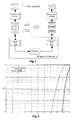
Fig. 2 is the performance of a Low Density Parity Check Code with n = 1024 and k = 512. This Figure shows the development of the Codeword Error Rate (CER), i.e. the decoding errors, when using a maximum-likelihood decoder and an iterative decoder in dependence on the erasure channel probability ε. As a reference curve, the lower bound according to Singleton is represented. The performance of the maximum-likelihood decoder approaches this theoretical limit. - Of considerable importance in a mobile broadcasting application is the capability of packet-level codes to cope with signal fades and outages to the effect that most of the lost and/or corrupted data packets can be restored without a retransmission request. Preferably, use is made of software-implemented packet-level decoders since these do not need a high expenditure for implementation, are easily and flexibly updated and can be adapted by use of terminals which do not need a specific hardware design for this purpose. The methods known to date suffer from the disadvantage that either, when using the iterative decoder, it is possible to apply a fast and efficient working decoding method which, however, will yield only poor recovery results, or, when using the maximum-likelihood decoder, the applied method will yield improved recovery results but necessitate a complex implementation.
- It is an object of the invention to provide a method for recovery of lost and/ or corrupted data which are transmitted from a transmitter device to a receiver device, wherein said method shall allow for a better and/or less complex recovery of data.
- According to the present invention, the above object is achieved by the features defined in claim 1.
- In a method for recovery of lost and/or corrupted data which are transmitted from a transmitter device to a receiver device, the data is first coded by an encoder connected to the transmitter device. Said encoder can be e.g. a packet-level encoder. The data is transmitted by the transmitter device via a transmission device to the receiver device. A transmitter device as defined in the context of the present invention is any device which is suitable for transmission of data from the transmitter device to the receiver device and/or vice versa. For instance, the transmitter device can be provided by using a mobile broadcasting system (e.g. DVB-H or MBMS). Further, the transmission of data can be carried by UMTS, for instance.
- By use of a decoder connected to the receiver device, the transmitted data is decoded through a Low Density Parity Check method wherein, during decoding, lost and/or corrupted data is recovered. According to the invention, in a first decoding step, use is made of an iterative decoder. In a second decoding step, use is made of a maximum-likelihood decoder; particularly, the second decoding step is performed exclusively when the data cannot be sufficiently recovered by the iterative decoder.
- In other words, the method will start with the first decoding step performed by the iterative decoder. In case of successful recovery of the lost and/or corrupted data by means of the iterative decoder, the recovered data is delivered. In case where a recovery of the data by means of the iterative decoder cannot be successfully performed, there is initiated the second decoding step which is performed by the maximum-likelihood decoder. This makes it possible to reduce the number of times that the maximum-likelihood decoder is used. Considering, for instance, the performance developments according to
Fig. 2 which are known from the state of the art, and further assuming a channel-erasure rate of 0.4, it is evident that the iterative decoder will in 2% of the cases not be capable to recover the lost and/or corrupted data. Consequently, in the illustrated example, the maximum-likelihood decoder would be used in only 2% of the cases. Since the iterative decoder is used in the other 98% of the cases and since this decoder is faster and simpler in operation, the method of the invention accomplishes a considerable simplification in the recovery of lost and/or corrupted data. Particularly, the method is applicable also in receiver devices which include a processor with lower performance capabilities, which e.g. is not suited for a continuous operation in the Maximum-Likelihood Method. According to the state of the art, such a processor would presently only allow the use of the iterative decoding method, which would result in a deterioration of the recovery rate. By the method of the invention, a high recovery rate can be obtained also with less-performing processors. Thus, according to the invention, the proposed method makes it possible to reach the performance of a maximum-likelihood decoder by use of less complex means. - Both the encoder, which is connected to the transmitter device, and the decoder, which is connected to the receiver device, can be realized in hardware or software. Particularly, the encoder and/or the decoder can be realized as software which is implemented in the transmitter device and/or the receiver device.
- Preferably, the coding and decoding of the data is carried out on the packet level, i.e. in the network layer of the OSI layer model.
- To reduce the computing power required for the maximum-likelihood decoder in the second decoding step, a low-density parity-check matrix shall be used at the decoder. Those data packets which could be recovered neither by the iterative decoder nor by the maximum-likelihood decoder, are considered to have not been correctly transmitted so that renewed transmission of the data packets by the transmitter device can be initiated.
- Preferably, for reducing the complexity of the maximum-likelihood decoder an abortion parameter is defined, wherein the computations for recovery of lost and/or corrupted data by the maximum-likelihood decoder are aborted if the value α in the structured Gaussian elimination performed by the maximum-likelihood decoder exceeds the amount of the selected abortion parameter. The abortion parameter preferably defines an upper bound for the size of the used matrix on which Gaussian elimination is applied.
- In principle, a maximum-likelihood decoder for use with Low Density Parity Check Codes can be based on smart efficient Gaussian elimination methods in the binary field, as described e.g. in D. Burshtein and G. Miller, "An efficient maximum likelihood decoding of LDPC codes over the binary erasure channel", IEEE Transactions on Information Theory, Volume 50, no. II, pp. 2837-2844, November 2004, or E. Paoloni, G. Liva, M. Balazs and M. Chiani, "Generalized IRA Erasure Correcting Codes for Maximum Likelihood Decoding", submitted to IEEE Communication Letters 2008. Preferably, the so-called structured Gaussian elimination is used. Further details for the definition of the abortion parameter will be rendered in the passages dealing with
Fig. 3 within the description of figures of the present application. - Preferably, the computations for recovery of lost and/or corrupted data by the maximum-likelihood decoder are aborted if the value alpha in the structured Gaussian elimination performed by the maximum-likelihood decoder exceeds the selected abortion parameter. Also the value α in the structured Gaussian elimination will be described in greater detail in said passages dealing with
Fig. 3 of the present application. - The amount of the abortion parameter can be selected by the user of the receiver device on the basis of the available computing power of the receiver device, the current operational burden imposed on a processor of the receiver device, the desired quality of service and/or the available capacity of an energy store of the receiver device. Thus, for instance, it is possible to improve the quality of the recovery rate by increasing the abortion parameter. Thereby, the quality of service can be improved. If, by contrast, the abortion parameter is decreased, it is rendered possible e.g. to reduce the operational burden of a processor of the receiver device or the power consumption of the receiver device.
- Thus, by the definition of the abortion parameter, there is created an additional degree of freedom which makes it possible to adapt the decoder of the receiver device to existing marginal conditions and thus make it more user-friendly and/or reliable.
- Preferably, upon abortion of the computation for recovery of lost and/or corrupted data by the maximum-likelihood decoder, all that is performed is the delivery of the correctly transmitted and/or recovered data by the decoder. Further, an error message can be generated by the decoder. An error message primarily means that the non-recovered data and data packets are reported as missing so that a new transmission will be initiated.
- A further, independent invention relates to the use of a method, particularly as described in the present application, for wireless or wire-bound transmission of data between a transmitter device and a receiver device.
- Preferred embodiments of the invention will be described in greater detail hereunder with reference to the accompanying drawings, wherein:
- Fig. 1
- is a flow diagram of the data transmission between a transmitter device and a receiver device as practicable also in the method of the invention;
- Fig. 2
- is a graphical representation of the Codeword Error Rate in dependence on the Channel Erasure Rare according to the state of the art;
- Figs. 3a-3c
- indicate the computations for structured Gaussian elimination,
- Fig. 4
- is a graphical representation of the Codeword Error Rate in dependence on the Channel Erasure Rare with various abortion parameters (a) according to a possible embodiment of the invention; and
- Fig. 5
- is a schematic representation of a transmitter and receiver device for performing the inventive method.
- As already discussed in the introduction to the specification, a transmission of data packets is performed from a transmitter device (left-hand side) to a receiver device (right-hand side) in the manner outlined in
Fig. 1 . Along with a number k of information packets, a number m of parity packets are transmitted, resulting in the transmission of a total of n = m + k codeword packets. By exploiting this redundancy, it is possible to recover lost and/or corrupted data by means of the packet-level encoder. -
Fig. 3 schematically shows the principal procedure of the Gaussian elimination. U represents a sub-matrix of H and is formed by the columns of H located at the positions corresponding to lost and/or corrupted data packets. For easier explanation,Fig. 3 is presented under the assumption that all of the erased packets are adjacent to each other, i.e. contiguous, and are arranged at the end of the packet-level codeword. For solving this system of equations, U has to be brought into the diagonal form. This is possible under the condition that U comprises the largest possible number of independent rows and columns i.e. that rank (U) is equal to the number of erased packets (full rank criterion). - The structured Gaussian elimination is performed in the following manner: First, U is brought into an approximately triangular form. This is effected by simple permutations of the rows/columns (
Fig. 3a ). In a second step, the matrix B inFig. 3a is zeroed-out by row sums, thus generating a structure as shown inFig.3b . The above-mentioned first two steps will result in a complexity that is O(u2), where u represents the size of the erased bit patterns. - In a third step, "brute-force Gaussian elimination" is applied to the matrix A' in
Fig. 3b . This will lead to an identity matrix I. The third step has a complexity that is O(alpha3), where alpha represents the number of columns of the matrix A'. - It is evident that the equation system represented by the matrix on the right-hand side in
Fig. 3c can be solved by back substitution. The described method is applicable exclusively if U fulfils the "full rank" criterion. - Already for medium block lengths, the complexity of a decoder of the above type is dominated by the amount of alpha. The complexity of the iterative decoder is linear, however at the penalty of a reduced decoder performance.
- Since, in many applications, such as audio- and video-streaming, the processor performance in mobile end devices is insufficient for a permanent maximum-likelihood decoding, the inventive method is useful to perform an improved data transmission to the above devices in spite of said insufficiency. Apart from the use of the iterative decoder in the first decoding step and the use of the maximum-likelihood decoder in the second decoding step if the first decoding step has not been successful, further possibilities for adaptation are offered by varying the parameter a. This parameter preferably defines the upper bound of the size of matrix A', The complexity of the illustrated maximum-likelihood algorithm will be dictated by alpha, i.e. the number of columns of the matrix A'. Alpha primarily depends on the channel-erasure rate ε, i.e. the higher the probability of erasure of data on a channel is, the higher the value of alpha will be. In case of low probabilities of a channel erasure, alpha can assume the value zero.
- The adapting of the complexity of the maximum-likelihood decoder is performed in that each occurrence where - after U has been brought into the triangular form according to
Fig. 3a - alpha exceeds the value of the parameter a, will cause the decoder to output an error message and deliver exclusively the correctly transmitted and/or recovered data packets. Already by the use of an iterative decoder and the subsequent use of a maximum-likelihood decoder in case that a restoration of data by the iterative decoder should fail, it is accomplished to reach the performance of a maximum-likelihood decoder while nonetheless requiring a lesser degree of complexity. By the subsequent adaptation of the parameter a, the complexity of the decoder can be reduced even further, which is made possible by defining an upper limit for the size of the matrix subjected to the Gaussian elimination. Thereby, the maximum-likelihood decoder will be stopped already at an early point of time. The above step, i.e. the adapting of the parameter a, is effective to cause a shifting of the performance of the decoder. The larger a is, the closer the complexity and the performance of the decoder will come to the Maximum-Likelihood method. The smaller a is, the closer the complexity and the performance of the decoder will come to the iterative method. - Shown in
Fig. 4 is the codeword error rate in dependence on ε for various values of the parameter a. Thus values used are a = 0 (corresponding to using the iterative decoder exclusively), a = 4, a = 8, a= 16, a = 24, a = 32 and a = ∞ (corresponding to using only the maximum-likelihood decoder without restrictions). In this manner, a smoother transition in performance can be reached between exclusive use of an iterative decoder and exclusive use of a maximum-likelihood decoder. For instance, the complexity of an application of the Gaussian elimination to an 8 x 8 matrix is 8 : 43 = 23 = 8 times larger than the complexity of an application of the Gaussian elimination to a 4 x 4 matrix. -
Fig. 5 schematically depicts atransmitter device 10 and areceiver device 12 wherein, via thetransmission system 18 which is e.g. a UMTS connection, data is transmitted from thetransmitter device 10 to thereceiver device 12. On the transmitting side, the data is encoded by theencoder 14 connected totransmitter device 10. On the receiving side, the data is decoded by the decoder connected toreceiver device 12. In the process, use is made of the Low Density Parity Check method so that lost and/or corrupted data will be recovered during decoding. A first decoding step is performed by use of theiterative decoder 16a. In case that an attempt at recovery of the data by theiterative decoder 16a is not successful, the maximum-likelihood decoder 16b will be used in a second decoding step. The receiver device may comprise aprocessor 22 and/or anenergy store 20 such as e.g. a storage battery, and may be configured as amobile receiver device 12.
Claims (9)
- A method for recovery of lost and/or corrupted data transmitted from a transmitter device (10) to a receiver device (12), said method comprising the steps of:coding said data by means of an encoder (14) connected to the transmitter device (10),transmitting said data from the transmitter device (10) to the receiver device (12) via a transmission system (18), anddecoding said data, through application of a Low Density Parity Check method, by means of a decoder (16) connected to the receiver device (12), wherein lost and/or corrupted data is restored during decoding,characterized in that
in a first decoding step, an iterative decoder (16a) is used, and
in a second decoding step, a maximum-likelihood decoder (16b) is used,
said second decoding step being performed if said data cannot be sufficiently recovered by the iterative decoder (16a). - The method according to claim 1, characterized in that said second decoding step is performed exclusively if said data cannot be sufficiently recovered by the iterative decoder (16a).
- The method according to claim 1 or 2, characterized in that the coding and decoding of said data is performed on the OSI packet level, application level, transport level, or link level.
- The method according to any one of claims 1 to 3, characterized in that said data is transmitted in the form of data packets.
- The method according to any one of claims 1 to 4, characterized by an abortion parameter (a), wherein the computations for recovery of lost and/or corrupted data by the maximum-likelihood decoder (16b) are aborted if the value alpha in the structured Gaussian elimination performed by the maximum-likelihood decoder (16b) exceeds the amount of the selected abortion parameter (a), whereby the abortion parameter (a) preferably defines the upper bound for the size of the matrix (A').
- The method according to claim 5, characterized in that the amount of the abortion parameter (a) is selected by a user of the receiver device (12) on the basis of the available computing power of the receiver device (12), the current operational burden imposed on a processor (22) of the receiver device (12), the desired quality of service, and/or the available capacity of an energy store (20) of the receiver device (12) particularly of the mobile type.
- The method according to claim 5, characterized in that, upon abortion of the computations for recovery of the lost and/or corrupted data by the maximum-likelihood decoder (16b), said decoder (16) delivers only the correctly transmitted data and/or the recovered data, and particularly generates an error message.
- The method according to claims 1 to 7, characterized in that the abortion parameter (a) defines the maximum number of columns in the matrix (A') for which maximum-likelihood decoder (16b) will proceed with the Gaussian elimination on (A').
- Use of the method according to any one of claims 1 to 8 for wireless or wire-bound transmission of data between a transmitter device (10) and a receiver device (12), the transmitted data particularly being a video- and/or audio stream for a mobile receiver device (12).
Priority Applications (3)
| Application Number | Priority Date | Filing Date | Title |
|---|---|---|---|
| EP08156794A EP2134018A1 (en) | 2008-05-23 | 2008-05-23 | Method for recovery of lost and/ or corrupted data |
| DE102009017540A DE102009017540B4 (en) | 2008-05-23 | 2009-04-17 | Procedure for recovering lost and / or damaged data |
| US12/386,486 US8413008B2 (en) | 2008-05-23 | 2009-04-17 | Method for recovery of lost and/or corrupted data |
Applications Claiming Priority (1)
| Application Number | Priority Date | Filing Date | Title |
|---|---|---|---|
| EP08156794A EP2134018A1 (en) | 2008-05-23 | 2008-05-23 | Method for recovery of lost and/ or corrupted data |
Publications (1)
| Publication Number | Publication Date |
|---|---|
| EP2134018A1 true EP2134018A1 (en) | 2009-12-16 |
Family
ID=40151319
Family Applications (1)
| Application Number | Title | Priority Date | Filing Date |
|---|---|---|---|
| EP08156794A Ceased EP2134018A1 (en) | 2008-05-23 | 2008-05-23 | Method for recovery of lost and/ or corrupted data |
Country Status (3)
| Country | Link |
|---|---|
| US (1) | US8413008B2 (en) |
| EP (1) | EP2134018A1 (en) |
| DE (1) | DE102009017540B4 (en) |
Cited By (5)
| Publication number | Priority date | Publication date | Assignee | Title |
|---|---|---|---|---|
| WO2012025457A1 (en) * | 2010-08-24 | 2012-03-01 | Deutsches Zentrum für Luft- und Raumfahrt e.V. | Method for recovery of lost data and for correction of corrupted data |
| EP3142280A1 (en) * | 2015-09-09 | 2017-03-15 | Alcatel Lucent | Method, system and computer readable medium for the transmission of symbols between at least two telecommunication apparatus |
| CN108918930A (en) * | 2018-09-11 | 2018-11-30 | 广东石油化工学院 | Power signal self-adapting reconstruction method in a kind of load decomposition |
| CN108918928A (en) * | 2018-09-11 | 2018-11-30 | 广东石油化工学院 | Power signal self-adapting reconstruction method in a kind of load decomposition |
| CN109309513A (en) * | 2018-09-11 | 2019-02-05 | 广东石油化工学院 | A kind of electric-power wire communication signal self-adapting reconstruction method |
Families Citing this family (13)
| Publication number | Priority date | Publication date | Assignee | Title |
|---|---|---|---|---|
| US8959182B1 (en) * | 2008-04-15 | 2015-02-17 | Crimson Corporation | Systems and methods for computer data recovery and destruction |
| CN101902315B (en) * | 2009-06-01 | 2013-04-17 | 华为技术有限公司 | Retransmission method, device and communication system based on forward error correction |
| US8375278B2 (en) * | 2009-07-21 | 2013-02-12 | Ramot At Tel Aviv University Ltd. | Compact decoding of punctured block codes |
| US8516351B2 (en) * | 2009-07-21 | 2013-08-20 | Ramot At Tel Aviv University Ltd. | Compact decoding of punctured block codes |
| US9397699B2 (en) * | 2009-07-21 | 2016-07-19 | Ramot At Tel Aviv University Ltd. | Compact decoding of punctured codes |
| US8516352B2 (en) * | 2009-07-21 | 2013-08-20 | Ramot At Tel Aviv University Ltd. | Compact decoding of punctured block codes |
| JP5388351B2 (en) * | 2009-11-19 | 2014-01-15 | 株式会社Nttドコモ | Receiving apparatus and receiving method |
| JP5792256B2 (en) * | 2013-10-22 | 2015-10-07 | 日本電信電話株式会社 | Sparse graph creation device and sparse graph creation method |
| US9158633B2 (en) | 2013-12-24 | 2015-10-13 | International Business Machines Corporation | File corruption recovery in concurrent data protection |
| WO2015141903A1 (en) * | 2014-03-17 | 2015-09-24 | 엘지전자 주식회사 | Method and device for decoding low density parity check code for forward error correction in wireless communication system |
| JP6504162B2 (en) * | 2014-05-22 | 2019-04-24 | 日本電気株式会社 | Terminal, packet decoding method, and storage medium storing program |
| CN112015325B (en) * | 2019-05-28 | 2024-03-26 | 阿里巴巴集团控股有限公司 | Method for generating decoding matrix, decoding method and corresponding device |
| CN117459076B (en) * | 2023-12-22 | 2024-03-08 | 国网湖北省电力有限公司经济技术研究院 | MP decoding-based LDPC erasure code decoding method, system, equipment and storable medium |
Citations (4)
| Publication number | Priority date | Publication date | Assignee | Title |
|---|---|---|---|---|
| US20030012315A1 (en) * | 2001-07-06 | 2003-01-16 | John Fan | System and method for multistage error correction coding wirelessly transmitted information in a multiple antennae communication system |
| US20060059410A1 (en) * | 2004-09-13 | 2006-03-16 | Conexant Systems, Inc. | Systems and methods for multistage signal detection in mimo transmissions and iterative detection of precoded OFDM |
| WO2007068554A1 (en) * | 2005-12-12 | 2007-06-21 | Thomson Holding Germany Gmbh & Co. Ohg | Serial concatenation scheme and its iterative decoding using an inner ldpc and an outer bch code |
| DE102006028947A1 (en) * | 2006-06-23 | 2007-12-27 | Technische Universität Kaiserslautern | Receiver for receiving and interference reduced issuing data, has two data receiving units, where one data receiving unit is provided to receive receiving data set and another data receiving unit receives another receiving data set |
Family Cites Families (6)
| Publication number | Priority date | Publication date | Assignee | Title |
|---|---|---|---|---|
| KR100996029B1 (en) * | 2003-04-29 | 2010-11-22 | 삼성전자주식회사 | Apparatus and method for coding of low density parity check code |
| US20050268202A1 (en) * | 2004-05-28 | 2005-12-01 | Molisch Andreas F | Quasi-block diagonal low-density parity-check code for MIMO systems |
| DE102004053656B4 (en) * | 2004-09-10 | 2006-11-30 | Technische Universität Dresden | Method for processing signals according to methods with block-based error protection codes |
| CN100550655C (en) * | 2004-11-04 | 2009-10-14 | 中兴通讯股份有限公司 | A kind of encoder/decoder of low density parity check code and generation method thereof |
| EP1829223B1 (en) * | 2004-12-22 | 2013-02-13 | LG Electronics Inc. | Parallel, layered decoding for Low-Density Parity-Check (LDPC) codes |
| JP4620132B2 (en) * | 2005-12-20 | 2011-01-26 | 三菱電機株式会社 | Parity check matrix generation method, encoding method, communication apparatus, communication system, encoder |
-
2008
- 2008-05-23 EP EP08156794A patent/EP2134018A1/en not_active Ceased
-
2009
- 2009-04-17 US US12/386,486 patent/US8413008B2/en active Active
- 2009-04-17 DE DE102009017540A patent/DE102009017540B4/en not_active Expired - Fee Related
Patent Citations (4)
| Publication number | Priority date | Publication date | Assignee | Title |
|---|---|---|---|---|
| US20030012315A1 (en) * | 2001-07-06 | 2003-01-16 | John Fan | System and method for multistage error correction coding wirelessly transmitted information in a multiple antennae communication system |
| US20060059410A1 (en) * | 2004-09-13 | 2006-03-16 | Conexant Systems, Inc. | Systems and methods for multistage signal detection in mimo transmissions and iterative detection of precoded OFDM |
| WO2007068554A1 (en) * | 2005-12-12 | 2007-06-21 | Thomson Holding Germany Gmbh & Co. Ohg | Serial concatenation scheme and its iterative decoding using an inner ldpc and an outer bch code |
| DE102006028947A1 (en) * | 2006-06-23 | 2007-12-27 | Technische Universität Kaiserslautern | Receiver for receiving and interference reduced issuing data, has two data receiving units, where one data receiving unit is provided to receive receiving data set and another data receiving unit receives another receiving data set |
Non-Patent Citations (3)
| Title |
|---|
| D. BURSHTEIN; G. MILLER: "An efficient maximum likelihood decoding of LDPC codes over the binary erasure channel", IEEE TRANSACTIONS ON INFORMATION THEORY, vol. 50, no. II, November 2004 (2004-11-01), pages 2837 - 2844, XP011121168, DOI: doi:10.1109/TIT.2004.836694 |
| E. PAOLONI ET AL.: "Generalized IRA Erasure Correcting Codes for Maximum Likelihood Decoding", IEEE COMMUNICATION LETTERS, 2008 |
| ENRICO PAOLINI ET AL.: "Low-Complexity LDPC Codes with Near-Optimum Performance over the BEC", SUBMISSION FOR ADVANCED SATELLITE MOBILE SYSTEMS, 2008, 21 April 2008 (2008-04-21), Cornell University Library, XP002509841, Retrieved from the Internet <URL:http://arxiv.org/abs/0804.2991v1> [retrieved on 20090109] * |
Cited By (11)
| Publication number | Priority date | Publication date | Assignee | Title |
|---|---|---|---|---|
| WO2012025457A1 (en) * | 2010-08-24 | 2012-03-01 | Deutsches Zentrum für Luft- und Raumfahrt e.V. | Method for recovery of lost data and for correction of corrupted data |
| US9015565B2 (en) | 2010-08-24 | 2015-04-21 | Deutsches Zentrum Fuer Luft-Und Raumfahrt E.V. | Method for recovery of lost data and for correction of corrupted data |
| EP3142280A1 (en) * | 2015-09-09 | 2017-03-15 | Alcatel Lucent | Method, system and computer readable medium for the transmission of symbols between at least two telecommunication apparatus |
| WO2017041929A1 (en) * | 2015-09-09 | 2017-03-16 | Alcatel Lucent | Method, system and computer readable medium for the transmission of symbols between at least two telecommunication apparatus |
| TWI628932B (en) * | 2015-09-09 | 2018-07-01 | 阿卡特朗訊公司 | Method, system and computer readable medium for the transmission of symbols between at least two telecommunication apparatus |
| CN108918930A (en) * | 2018-09-11 | 2018-11-30 | 广东石油化工学院 | Power signal self-adapting reconstruction method in a kind of load decomposition |
| CN108918928A (en) * | 2018-09-11 | 2018-11-30 | 广东石油化工学院 | Power signal self-adapting reconstruction method in a kind of load decomposition |
| CN109309513A (en) * | 2018-09-11 | 2019-02-05 | 广东石油化工学院 | A kind of electric-power wire communication signal self-adapting reconstruction method |
| CN108918928B (en) * | 2018-09-11 | 2020-11-10 | 广东石油化工学院 | Power signal self-adaptive reconstruction method in load decomposition |
| CN108918930B (en) * | 2018-09-11 | 2020-12-22 | 广东石油化工学院 | Power signal self-adaptive reconstruction method in load decomposition |
| CN109309513B (en) * | 2018-09-11 | 2021-06-11 | 广东石油化工学院 | Adaptive reconstruction method for power line communication signals |
Also Published As
| Publication number | Publication date |
|---|---|
| US20090292966A1 (en) | 2009-11-26 |
| US8413008B2 (en) | 2013-04-02 |
| DE102009017540B4 (en) | 2011-01-20 |
| DE102009017540A1 (en) | 2009-12-10 |
Similar Documents
| Publication | Publication Date | Title |
|---|---|---|
| EP2134018A1 (en) | Method for recovery of lost and/ or corrupted data | |
| US9548837B2 (en) | Method and apparatus for transmitting and receiving a data block in a wireless communication system | |
| JP4975301B2 (en) | Concatenated iterative and algebraic coding | |
| WO2017156792A1 (en) | Transmission of new data in a hybrid automatic repeat request (harq) retransmission with polar coded transmissions | |
| US7831884B2 (en) | Method of correcting message errors using cyclic redundancy checks | |
| US8386880B2 (en) | Method for transmitting non-binary codes and decoding the same | |
| WO2014044072A1 (en) | Generation method and generation device for mixed polar code | |
| CN107423161B (en) | Applied to the adaptive LDPC code error-correcting code system and method in flash memory | |
| EP1908171A2 (en) | Forward error-correcting (fec) coding and streaming | |
| WO2008034289A1 (en) | Bit mapping scheme for an ldpc coded 32apsk system | |
| CN103269229A (en) | Mixed iterative decoding method for LDPC-RS two-dimensional product code | |
| WO2010103905A1 (en) | Methods and devices for providing unequal error protection code design from probabilistically fixed composition codes | |
| CN104135345B (en) | A kind of cross-layer decoding method applied to long evolving system | |
| WO2003103152A2 (en) | Soft decoding of linear block codes | |
| CN107395326B (en) | Degree distribution optimization algorithm and device in LT code | |
| Ma et al. | Implicit partial product-LDPC codes using free-ride coding | |
| US20080208939A1 (en) | Decoder device and decoding method | |
| Chaudhary et al. | Error control techniques and their applications | |
| RU2667370C1 (en) | Method for decoding linear cascade code | |
| EP2234304A1 (en) | Method for recovery of lost and/ or corrupted data | |
| Zhao et al. | Concatenated polar-coded multilevel modulation | |
| EP1901438A2 (en) | An interleaving scheme for a LDPC coded QPSK/8PSK system | |
| US20110173509A1 (en) | Bit mapping scheme for an ldpc coded 16apsk system | |
| Lim et al. | Performance improvement of rateless code by non-uniform selection of messages in encoding | |
| Kukieattikool et al. | Variable‐rate staircase codes with RS component codes for optical wireless transmission |
Legal Events
| Date | Code | Title | Description |
|---|---|---|---|
| PUAI | Public reference made under article 153(3) epc to a published international application that has entered the european phase |
Free format text: ORIGINAL CODE: 0009012 |
|
| 17P | Request for examination filed |
Effective date: 20090724 |
|
| AK | Designated contracting states |
Kind code of ref document: A1 Designated state(s): AT BE BG CH CY CZ DE DK EE ES FI FR GB GR HR HU IE IS IT LI LT LU LV MC MT NL NO PL PT RO SE SI SK TR |
|
| AX | Request for extension of the european patent |
Extension state: AL BA MK RS |
|
| AKX | Designation fees paid |
Designated state(s): AT BE BG CH CY CZ DE DK EE ES FI FR GB GR HR HU IE IS IT LI LT LU LV MC MT NL NO PL PT RO SE SI SK TR |
|
| 17Q | First examination report despatched |
Effective date: 20120207 |
|
| STAA | Information on the status of an ep patent application or granted ep patent |
Free format text: STATUS: THE APPLICATION HAS BEEN REFUSED |
|
| 18R | Application refused |
Effective date: 20120817 |