JP4975301B2 - Concatenated iterative and algebraic coding - Google Patents
Concatenated iterative and algebraic coding Download PDFInfo
- Publication number
- JP4975301B2 JP4975301B2 JP2005318997A JP2005318997A JP4975301B2 JP 4975301 B2 JP4975301 B2 JP 4975301B2 JP 2005318997 A JP2005318997 A JP 2005318997A JP 2005318997 A JP2005318997 A JP 2005318997A JP 4975301 B2 JP4975301 B2 JP 4975301B2
- Authority
- JP
- Japan
- Prior art keywords
- decoder
- encoder
- block
- data
- symbols
- Prior art date
- Legal status (The legal status is an assumption and is not a legal conclusion. Google has not performed a legal analysis and makes no representation as to the accuracy of the status listed.)
- Expired - Fee Related
Links
Images


Classifications
-
- H—ELECTRICITY
- H04—ELECTRIC COMMUNICATION TECHNIQUE
- H04L—TRANSMISSION OF DIGITAL INFORMATION, e.g. TELEGRAPHIC COMMUNICATION
- H04L1/00—Arrangements for detecting or preventing errors in the information received
-
- H—ELECTRICITY
- H03—ELECTRONIC CIRCUITRY
- H03M—CODING; DECODING; CODE CONVERSION IN GENERAL
- H03M13/00—Coding, decoding or code conversion, for error detection or error correction; Coding theory basic assumptions; Coding bounds; Error probability evaluation methods; Channel models; Simulation or testing of codes
- H03M13/29—Coding, decoding or code conversion, for error detection or error correction; Coding theory basic assumptions; Coding bounds; Error probability evaluation methods; Channel models; Simulation or testing of codes combining two or more codes or code structures, e.g. product codes, generalised product codes, concatenated codes, inner and outer codes
- H03M13/2957—Turbo codes and decoding
- H03M13/296—Particular turbo code structure
- H03M13/2972—Serial concatenation using convolutional component codes
-
- H—ELECTRICITY
- H03—ELECTRONIC CIRCUITRY
- H03M—CODING; DECODING; CODE CONVERSION IN GENERAL
- H03M13/00—Coding, decoding or code conversion, for error detection or error correction; Coding theory basic assumptions; Coding bounds; Error probability evaluation methods; Channel models; Simulation or testing of codes
- H03M13/63—Joint error correction and other techniques
- H03M13/6331—Error control coding in combination with equalisation
-
- H—ELECTRICITY
- H03—ELECTRONIC CIRCUITRY
- H03M—CODING; DECODING; CODE CONVERSION IN GENERAL
- H03M13/00—Coding, decoding or code conversion, for error detection or error correction; Coding theory basic assumptions; Coding bounds; Error probability evaluation methods; Channel models; Simulation or testing of codes
- H03M13/03—Error detection or forward error correction by redundancy in data representation, i.e. code words containing more digits than the source words
- H03M13/05—Error detection or forward error correction by redundancy in data representation, i.e. code words containing more digits than the source words using block codes, i.e. a predetermined number of check bits joined to a predetermined number of information bits
- H03M13/11—Error detection or forward error correction by redundancy in data representation, i.e. code words containing more digits than the source words using block codes, i.e. a predetermined number of check bits joined to a predetermined number of information bits using multiple parity bits
- H03M13/1102—Codes on graphs and decoding on graphs, e.g. low-density parity check [LDPC] codes
- H03M13/1148—Structural properties of the code parity-check or generator matrix
- H03M13/116—Quasi-cyclic LDPC [QC-LDPC] codes, i.e. the parity-check matrix being composed of permutation or circulant sub-matrices
Description
本発明は誤り訂正(EC)の符号化に関し、さらに特定すると連結された誤りの符号化および復号化に関する。 The present invention relates to error correction (EC) coding, and more particularly to coding and decoding of concatenated errors.
デジタル通信システムでは、情報はチャンネル上で送信器から受信器へと通信され、それは通常ではある程度の量のノイズによって損なわれる。同様に、デジタル記憶システム(例えば磁気、光、半導体、および有機の記憶システム)では記憶媒体への送信、記憶媒体への保存、および記憶媒体からのリードバックの中で情報への損傷が導入される可能性が高い。ビット誤り率(BER)と称される誤りの発生する率はデジタル通信リンクおよびデータ保存に関して極めて重要な設計基準である。普通、BERはビットの合計数に対する導入されるビット誤りの数の比であると定義される。普通、BERは用途に応じて決まる特定の値よりも下に保たれなければならない。通信および記憶システムの両方で、ノイズおよび符号間干渉(ISI)のような損傷の存在下で可能な限りオリジナルの情報が正確に回収されることを確実化するために、オリジナルのメッセージへの冗長性の追加を基本とするECの符号化技術が一般的に使用される。ECコードの紹介および概観は本願明細書でその全文を参照で組み入れるBernard SkalarとFredric J.Harrisの「The ABCs of linear block codes」,IEEE Signal Processing Magazine,July 2004,pp.14〜35に見出されることが可能である。 In a digital communication system, information is communicated over a channel from a transmitter to a receiver, which is usually corrupted by a certain amount of noise. Similarly, digital storage systems (eg, magnetic, optical, semiconductor, and organic storage systems) introduce damage to information during transmission to storage media, storage on storage media, and readback from storage media. There is a high possibility. The rate of occurrence of errors, referred to as bit error rate (BER), is a very important design criterion for digital communication links and data storage. Usually, BER is defined as the ratio of the number of bit errors introduced to the total number of bits. Normally, the BER must be kept below a specific value that depends on the application. To ensure that the original information is recovered as accurately as possible in the presence of damage such as noise and intersymbol interference (ISI) in both communication and storage systems, redundancy to the original message EC coding techniques based on the addition of gender are commonly used. An introduction and overview of the EC code is provided by Bernard Skalar and Fredric J., which is incorporated herein by reference in its entirety. Harris "The ABCs of linear block codes", IEEE Signal Processing Magazine, July 2004, pp. 14-35.
概して、ECデコーダは2つの主要なクラス、すなわち代数型のハード・デコーダと反復型のソフト・デコーダに分類される。ハード・デコーディングは、受信された信号もしくは記憶媒体からリードバックされた信号サンプルがデジタル記号(例えば2進データのブロック)へと直接解読される処理に関し、それに対してソフト・デコーディングは、特定のサンプルが2進数0もしくは2進数1である確率といったさらに確率的な情報に結果としてつながる処理に関する。例えば、通常のソフト出力デコーダは各々の受信サンプルを表現するために4ビットで表わされる2進数の値を使用することが可能である。+7に近い値は受信2進数1を表わす高い確率を有すると考えられ、それに対して−8に近い値は受信2進数0を表わす高い確率を有すると考えられる。反復型の復号化は、前の信頼性に欠けるビット予測からさらに信頼性のあるビット予測を作り出すことによって復号化精度を向上させることが可能である。
In general, EC decoders fall into two main classes: algebraic hard decoders and iterative soft decoders. Hard decoding refers to the process in which a received signal or signal sample read back from a storage medium is directly decoded into digital symbols (eg, a block of binary data), whereas soft decoding is specific Is related to processing that results in more probabilistic information, such as the probability that the sample is binary 0 or binary 1. For example, a typical soft output decoder can use a binary value represented by 4 bits to represent each received sample. A value close to +7 is considered to have a high probability representing the received
反復型デコーダ(例えばターボ・デコーダ、低密度パリティ・チェック(LDPC)デコーダ、および反復型アレイ・デコーダ)は高い符号化利得という興味を引く特性を有する。符号化利得は、符号化されていない信号を上回る、符号化された信号が与える効率の増大として定義される。デシベルで表現される場合、符号化利得は、例えば送信電力の減少のレベルを示すことが可能であり、それは無符号に相対して特定の符号が使用されるときにチャンネルを通る同じデータ転送速度を維持するために達成されることが可能である。反復型デコーダの1つの特徴は、デコーダの符号化利得に関して決定済みの表現がないことである。動作の有界の数の観点から分析的に表現されることが可能であれば、或る表現が決定済みの表現であると言われる。例えば、無限の合計は概して決定済みであると考えられないであろう。反復型デコーダの符号化利得に関して決定済みの表現がないので、これらのデコーダの符号化利得は通常ではシミュレーションによって決定される。残念ながら、反復型デコーダの目標BERが極めて低い(例えば10−15以下)とき、デコーダのシミュレーションは現在のコンピュータ・システムを使用して実行不可能である。それゆえに例えば、特定の反復型デコーダがシミュレーションによって示されることで目標BERが10−5であるシステムに関して有意の符号化利得を示すことは可能であり得るが、しかし10−15の目標BERについてはその性能が判定されることは不可能である。さらに、反復型デコーダについては性能は低いBERで平坦化し易いことを経験的データが示す傾向にあり、反復型デコーダは妥当な数の反復ですべての誤りを訂正する役に立たない可能性があるというさらなる心配を呼び起こす。アレイ符号およびLDPC符号に関するさらなる情報は本願明細書にその全文を組み入れるJ.L.Fanの「Array codes as Low−Density Parity Check codes」,Proc.38th Allerton Conference on Communication,Control,and Computing,955〜956,Sept.2000に見出されることが可能である。ターボ符号に関するさらなる情報は本願明細書にその全文を組み入れるB.Skiarの「A Primer on Turbo Code Concepts」,pp.94〜102,IEEE Communications Magazine,December 1997に見出されることが可能である。 Iterative decoders (eg, turbo decoder, low density parity check (LDPC) decoder, and iterative array decoder) have the interesting property of high coding gain. Coding gain is defined as the increase in efficiency afforded by a coded signal over an uncoded signal. When expressed in decibels, the coding gain can indicate, for example, the level of transmit power reduction, which is the same data rate through the channel when a particular code is used relative to no code. Can be achieved. One feature of the iterative decoder is that there is no determined representation for the coding gain of the decoder. An expression is said to be a determined expression if it can be expressed analytically in terms of a bounded number of actions. For example, an infinite sum would generally not be considered determined. Since there is no determined representation for the coding gain of iterative decoders, the coding gain of these decoders is usually determined by simulation. Unfortunately, when the iterative decoder target BER is very low (e.g., 10-15 or less), decoder simulation is not feasible using current computer systems. Thus, for example, it may be possible to show a significant coding gain for a system with a target BER of 10 −5 by showing a specific iterative decoder by simulation, but for a target BER of 10 −15 Its performance cannot be determined. Further, empirical data tends to show that for iterative decoders, performance tends to be flattened at low BER, and iterative decoders may not be useful to correct all errors with a reasonable number of iterations. Raise worry. Additional information regarding array codes and LDPC codes can be found in J. Pat. L. Fan, “Array codes as Low-Density Parity Check codes”, Proc. 38th Allerton Conference on Communication, Control, and Computing, 955-956, Sept. Can be found in 2000. More information on turbo codes can be found in B.C. Skier's "A Primer on Turbo Code Concepts", pp. 94-102, IEEE Communications Magazines, December 1997.
他方で代数型デコーダ(例えばハミング・デコーダ、リード・ソロモン・デコーダ、Bose−Chaudhuri−Hocquenghem(BCH)デコーダ、および代数アレイ・デコーダ)は反復型デコーダよりも低効率(低い符号化利得)である可能性が高い。しかしながら、代数型デコーダの性能は任意に低い目標BERで分析的に計算されることが可能である。したがって、特定の目標BER、および予測されるチャンネル誤り率が与えられると、目標BERを満たすために特定の代数コードが使用されることが可能か否かを判定するために決定済みの表現が使用されることが可能である。 On the other hand, algebraic decoders (eg, Hamming decoder, Reed-Solomon decoder, Bose-Chauduri-Hocquenhem (BCH) decoder, and algebraic array decoder) can be less efficient (lower coding gain) than iterative decoders. High nature. However, the performance of an algebraic decoder can be calculated analytically with an arbitrarily low target BER. Thus, given a specific target BER and an expected channel error rate, the determined representation is used to determine whether a specific algebraic code can be used to meet the target BER. Can be done.
データ記憶用途については、訂正されたビット誤り率(すなわち誤り訂正の後のBER)は10−15以下の位数であることが好ましい。データ記憶用途では、例えば読み取りヘッドのミストラッキング、記録媒体に相対した読み取りヘッドの飛行高さ、ビット密度、およびシステムの信号対ノイズ比(SNR)の変動が原因でビット誤りが導入される可能性が高い。現在、データ記憶用途の目標は1平方インチ当たり1テラビット(1Tbit/in2)以上の記憶密度を実現することである。そのような高いビット密度は高い符号間干渉(ISI)を生じ、低いBERを実現する作業を複雑化する。さらに、そのような高いビット密度により、各々のビットが記録媒体上で占める物理的スペースが相対的に小さくなり、結果として相対的に低い信号強度につながり、それがSNRに影響を及ぼす。付け加えると、演算上複雑な符号化/復号化の仕組みは付随する復号化動作を高いビットレートで実行することを困難にする。
したがって、1Tbit/in2といった高いビット密度に通常では付随する大きいISIと低いSNRの複雑さにもかかわらず、10−15以下の訂正BERに結び付く符号化の仕組みに関するニーズが存在する。さらに、高いデータ転送速度で符号化/復号化を可能にするそのような符号化仕組みに関するニーズが存在する。 Thus, despite the complexity of large ISI and low SNR that normally accompany a high bit density such 1 Tbit / in 2, there is need for a coding leading to 10 -15 following correction BER mechanism. Furthermore, there is a need for such an encoding scheme that allows encoding / decoding at high data rates.
連結された代数型および反復型のデコーダの使用を含む誤り訂正符号化および復号化のための方法および装置によって先行技術の問題が、本発明の原理に従って対処される。反復型デコーダは高いBERから中程度のBERまでの誤りを効率的に下げるために使用され、その一方で代数型デコーダは低いBERで性能を保証する。 Prior art problems are addressed in accordance with the principles of the present invention by methods and apparatus for error correction encoding and decoding, including the use of concatenated algebraic and iterative decoders. Iterative decoders are used to efficiently reduce errors from high BER to moderate BER, while algebraic decoders guarantee performance at low BER.
本発明の一実施形態はEC符号化の方法であって、(1)代数型EC外部デコーダを使用して復号化され得る符号化されたデータを作り出すためにEC外部エンコーダを使用してデータのEC符号化を行なうステップ、および(2)1つまたは複数の反復型EC内部デコーダを使用して復号化され得るさらに符号化されたデータを作り出すために1つまたは複数のEC内部エンコーダを使用して符号化されたデータのさらなるEC符号化を行なうステップを含む。 One embodiment of the present invention is a method of EC encoding, comprising: (1) using an EC outer encoder to produce encoded data that can be decoded using an algebraic EC outer decoder; Performing EC encoding, and (2) using one or more EC inner encoders to produce further encoded data that can be decoded using one or more iterative EC inner decoders. Performing further EC encoding of the encoded data.
本発明の他の実施形態は、反復型EC内部デコーダおよび代数型EC外部デコーダをEC符号化されたデータに適用することにより、EC符号化されたデータの復号化を行なう方法である。反復型EC内部デコーダは、EC符号化されたデータ内の誤りをEC内部エンコーダによって作り出された冗長データの関数として訂正するように動作する。代数型EC外部エンコーダはEC符号化されたデータ内の誤りを、EC外部エンコーダによって作り出された冗長データを活用することによって訂正するように動作する。 Another embodiment of the present invention is a method for decoding EC encoded data by applying an iterative EC inner decoder and an algebraic EC outer decoder to the EC encoded data. The iterative EC inner decoder operates to correct errors in the EC encoded data as a function of redundant data produced by the EC inner encoder. An algebraic EC outer encoder operates to correct errors in EC encoded data by exploiting redundant data created by the EC outer encoder.
本発明の他の実施形態は、オリジナルのデータに外部エンコーダを適用し、引き続いて少なくとも1つの内部エンコーダを適用することによって作り出されたEC符号化されたデータの復号化のための方法である。この方法は(a)少なくとも1つの内部エンコーダに対応する少なくとも1つの内部デコーダをEC符号化されたデータに適用することで第1の復号化されたデータを作り出すステップ、(b)外部エンコーダに対応する少なくとも1つの反復型デコーダを第1の復号化されたデータに適用することで第2の復号化されたデータを作り出すステップ、および(c)外部エンコーダに対応する代数型デコーダを第2の復号化されたデータに適用することで出力の複合化されたデータを作り出すステップを含む。 Another embodiment of the present invention is a method for decoding EC-encoded data created by applying an outer encoder to original data and subsequently applying at least one inner encoder. The method includes (a) applying at least one inner decoder corresponding to at least one inner encoder to the EC-encoded data to produce first decoded data, (b) corresponding to the outer encoder Applying at least one iterative decoder to the first decoded data to produce second decoded data; and (c) second decoding an algebraic decoder corresponding to the outer encoder Generating composite data of the output by applying to the digitized data.
本発明の他の実施形態は、オリジナルのデータに外部エンコーダを適用し、引き続いて少なくとも1つの内部エンコーダを適用することによって作り出されたEC符号化されたデータの復号化のための連結されたデコーダである。このデコーダは(a)EC符号化されたデータを復号化して第1の復号化されたデータを作り出すように構成され、少なくとも1つの内部エンコーダに対応する少なくとも1つの内部デコーダ、(b)第1の復号化されたデータを複合化して第2の復号化されたデータを作り出すように構成され、外部エンコーダに対応する少なくとも1つの反復型デコーダ、および(c)第2の復号化されたデータを復号化して出力の復号化データを作り出すように構成され、外部エンコーダに対応する代数型デコーダを有する。 Another embodiment of the invention is a concatenated decoder for decoding EC-encoded data produced by applying an outer encoder to the original data and subsequently applying at least one inner encoder. It is. The decoder is configured to (a) decode EC-encoded data to produce first decoded data, at least one inner decoder corresponding to at least one inner encoder; (b) first At least one iterative decoder corresponding to the outer encoder, and (c) the second decoded data, wherein the decoded data is configured to decrypt the decoded data to produce a second decoded data. An algebraic decoder corresponding to the outer encoder is configured to decode and produce output decoded data.
本発明の他の実施形態は、(1)記号の第1のブロックを作り出すために外部エンコーダをデータの第1のブロックに適用し、(2)符号語の第1のブロックを作り出すために少なくとも1つの内部エンコーダを記号の第1のブロックに適用することによって作り出されたEC符号化されたデータの復号化のための連結されたデコーダである。この連結されたデコーダは、符号語の第1のブロックに対応する符号語の第2のブロックを復号化するように構成された少なくとも1つの内部デコーダを含む。符号語の第2のブロックの復号化は記号の第1のブロックに対応する記号の第2のブロックを発生する。少なくとも1つの内部デコーダは符号語の第2のブロック内の各々の符号語を独立して復号化する。少なくとも1つのこれらの符号語が内部デコーダによって復号化されることで記号の第2のブロック内の2つ以上の記号を発生する。この連結デコーダはまた、代数復号化の仕組みを記号の第2のブロックに適用してデータの第1のブロックに対応するデータの第2のブロックを作り出すように構成された代数型外部デコーダも有する。
本発明のその他の態様、特徴、および利点は以下の詳細な説明、添付の特許請求項、および添付の図面からさらに完全に明らかになるであろう。
Other embodiments of the invention (1) apply an outer encoder to the first block of data to create a first block of symbols and (2) at least to create a first block of codewords A concatenated decoder for decoding EC-encoded data created by applying one inner encoder to a first block of symbols. The concatenated decoder includes at least one inner decoder configured to decode a second block of codewords corresponding to the first block of codewords. Decoding the second block of codewords generates a second block of symbols that corresponds to the first block of symbols. At least one inner decoder independently decodes each codeword in the second block of codewords. At least one of these codewords is decoded by an inner decoder to generate two or more symbols in the second block of symbols. The concatenated decoder also has an algebraic outer decoder configured to apply an algebraic decoding scheme to the second block of symbols to produce a second block of data corresponding to the first block of data. .
Other aspects, features, and advantages of the present invention will become more fully apparent from the following detailed description, the appended claims, and the accompanying drawings.
本願明細書で「一実施形態」もしくは「或る実施形態」と言及する場合、その実施形態に関連して述べられる特定の特徴、構造、または特性が本発明の少なくとも1つの実施形態の中に含まれ得ることを意味する。本願明細書の様々な場所での「一実施形態では」という語句の表現は必ずしもすべてが同じ実施形態について言及しているわけではなく、別のもしくは代替選択肢の実施形態が必ずしも他の実施形態を互いに排除するわけでもない。 When referring to “one embodiment” or “an embodiment” herein, a particular feature, structure, or characteristic described in connection with that embodiment is among the at least one embodiment of the invention. It can be included. The phrases “in one embodiment” in various places in the specification are not necessarily all referring to the same embodiment, and alternative or alternative embodiments do not necessarily refer to other embodiments. Nor does it exclude each other.
(誤り訂正システム)
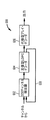
図1は本発明による範例のECシステム100を例示している。ECシステム100はECエンコーダ110およびECデコーダ124を有する。ECエンコーダ110はEC外部エンコーダ104および1つまたは複数のEC内部エンコーダ108を有する。ECデコーダ124は1つまたは複数のEC内部デコーダ118およびEC外部デコーダ122を有する。
(Error correction system)
FIG. 1 illustrates an
動作時では、外部エンコーダ104が符号化されたデータ106を作り出すために冗長データで入力データ102を符号化する。その後、符号化されたデータ106は一連の1つまたは複数の内部エンコーダ108へと送られ、そこでは符号化されたデータ112を作り出すために追加的なEC符号化が実行される。その後、符号化されたデータ112はチャンネル114(例えば送信または記憶チャンネル)を通して送られ、そこでは定常的に誤りがデータの中に導入される。(潜在的に誤りを含む)符号化されたデータはその後、(送信チャンネルのケースで)受信されるか、または(記憶チャンネルのケースで)回収され、その後、結果として符号化されたデータ116がECデコーダ124へと与えられる。デコーダ124内で、1つまたは複数の内部デコーダ118はチャンネルによって導入された誤りのうちのいくつかまたは全部を訂正するように動作する。内部デコーダの出力120は外部デコーダ122へと送られ、そこで残りの誤りのうちのいくつかまたは全部が訂正されることが可能である。最後に、回収されるかまたは部分的に回収されたデータ126がデコーダ124から出力される。
In operation, the external encoder 104 encodes the
エンコーダ110内で、外部エンコーダ104および(複数の)内部エンコーダ108は、外部エンコーダ104によって作り出される代数的復号化が可能な符号を備えた当該技術で知られているような多様なECエンコーダ(例えばターボ、二次元積符号(2DPC)、LDPC、ハミング、リード・ソロモン、BCH、およびアレイのエンコーダ)の適切な組み合わせであることが可能である。
Within
同様に、デコーダ124内で、(複数の)内部デコーダ118および外部デコーダ122はエンコーダ110を作り上げる複数のエンコーダに対応するECデコーダの適切な組み合わせであり、外部デコーダ122は少なくとも反復して復号化可能である。概して、(複数の)内部デコーダ118は(複数の)内部エンコーダ108および可能であれば外部エンコーダ104に対応する一連の1つまたは複数の反復型または代数型デコーダであることが可能である。
Similarly, within
(符号化)
図3は図1のエンコーダ110の範例となる実施形態300を例示しており、動作可能なように(内部)LDPCエンコーダ308に連結された(外部)アレイ・エンコーダ304を有する。動作時では、アレイ・エンコーダ304は送信もしくは記憶される入力データ302を受け取り、この入力データを符号化してアレイ符号化されたデータ306を作り出し、その後、アレイ符号化されたデータをLDPCエンコーダ308へと送る。その後、LDPCエンコーダ308がこのアレイ符号化されたデータを符号化してLDPC/アレイ符号化されたデータ310を作り出す。
(Coding)
FIG. 3 illustrates an
図4は図3のエンコーダ300の動作に付随する追加的な詳細を例示している。エンコーダ300によって符号化される入力データは最初にp本の横列×(q−r)本の縦列の複数ブロック302へとグループ化され、各々のブロックの記入事項は入力データの単一のビットであり、p、q、およびrは正の整数であり、0<r<qである。アレイ・エンコーダの用語で、(q−r)本の縦列は記号であると考えられる。したがってブロック302は(q−r)個のデータ記号312を備えたデータ・ブロックと考えられることが可能である。アレイ・エンコーダ304の動作は結果として、オリジナルの(q−r)個の記号312ならびにr個の符号(このケースではパリティ)の記号316を含む(p×q)個のブロック306につながる。その後、結果的に得られた(p×q)個のブロック306はLDPCエンコーダ308へと供給され、各々の縦列はブロック306内の他の縦列とは無関係に符号化される。LDPC符号化は結果としてデータ・ブロック306の各々の縦列へのhビットの符号(このケースではパリティ)の追加につながり、各々の長さが(p+h)のq個の符号語(例えば符号語318および320)を生じる。内部のLDPCエンコーダは様々な実施形態で、各々の縦列をその実施形態に最も適切であるように直列または並列で処理することが可能である。概して、並列の実施形態の選択肢は直列の実施形態に相対して内部エンコーダの動作のスピードを上げることが可能である。
FIG. 4 illustrates additional details associated with the operation of
代替選択肢の実施形態では、ブロック306の1つまたは複数の縦列が単一の符号語へと組み合わされ、各々の組み合わせは他とは無関係にLDPCエンコーダ308によって操作される。
In an alternative embodiment, one or more columns of
(検出)
図5、6、および7で例示されるデコーダの各々の実施形態では、ソフトインプット・ソフトアウトプット(SISO)のチャンネル検出器(例えば図5のSISOチャンネル検出器502)がチャンネルからデータを受け取る。このデータは内部エンコーダ308からのデータ・ブロック310の出力と実質的に同様に配列されるが、しかしそれはエンコーダとデコーダの間のチャンネルに付随するノイズおよび障害によって劣悪化されている可能性が高い。SISOチャンネル検出器はSISOアルゴリズム(例えばソフトアウトプット・ビタビ・アルゴリズム(SOVA))を使用してデータを処理し、受け取った各データ・ビットに関してソフト推定を出力する。この推定は−32から+31の範囲の6ビットの2進数の値の形式であることが可能である。その値が−32に近ければ、受け取ったデータ・ビットが2進の0として送信された可能性が極めて高いと考えられる。その値が+31に近ければ、受け取ったデータ・ビットが2進の1として送信された可能性が極めて高いと考えられる。チャンネル検出器によって作り出されるソフト推定はエンコーダによって作り出された(p+h)ビットのq個の符号語に対応する(p+h)個の6ビット値のq本の縦列へと分割され、ソフト・データのこれらq本の縦列は処理のためにデコーダの第1の段へと送られる。
(detection)
In each of the decoder embodiments illustrated in FIGS. 5, 6, and 7, a soft input / soft output (SISO) channel detector (eg,
(復号化)
図3のエンコーダの実施形態では、アレイ符号化されたデータが反復的および/または代数的に復号化されるので図5、6、および7に例示されるようにデコーダの実施形態について様々な選択肢が存在する。
(Decryption)
In the encoder embodiment of FIG. 3, the array-encoded data is decoded iteratively and / or algebraically, so there are various options for the decoder embodiment, as illustrated in FIGS. Exists.
符号語(例えば図4の縦列318)がチャンネルを通して送られ、チャンネル検出器によって処理され、1つまたは複数の内部エンコーダによって作用を受ける場合、いくつかの異なる可能なシナリオが存在し、それらは図2の表1に要約されるように外部デコーダへと入力されるデータに関連することに留意されたい。第1のシナリオでは、チャンネルによって誤りが導入されることはなく、受信される符号語はエンコーダからチャンネルへと送信された符号語に対応する。第2のシナリオでは、1つまたは複数の誤りがチャンネルによって符号語の中に導入されるが、しかしそれらの誤りは(複数の)内部デコーダによって訂正可能である。第3のシナリオでは、1つまたは複数の誤りがチャンネルによって導入され、それらの誤りは(複数の)内部デコーダが訂正を行なう能力を超えている。この第3のシナリオでは、符号化された記号(例えば図4のオリジナルのデータ記号312またはパリティ記号316)は内部デコーダ単独では回収不可能である。この回収不可能な記号は消失記号として規定され、その場所が外部デコーダに対するフラグを立てられる。第4のシナリオでは、誤りの性質はオリジナルの符号語が当初符号化されたそれとは異なる記号に対応するものを除いた他の有効な符号語に対してマップ化されるような性質である。このケースでは、データ記号またはパリティ記号が(複数の)内部デコーダによって回収されるが、しかしそれは符号化された記号ではない。このタイプの記号は誤り記号として知られている。第5のシナリオでは、誤りの性質はオリジナルの符号語がオリジナルの記号とは異なる記号に対応する無効な符号語に対してマップ化されるような性質である。このケースでは、(複数の)内部デコーダは無効な符号語を間違った記号へと復号化する。それ自体で、これは誤り記号の別の範例である。
When codewords (eg,
(複数の)内部デコーダの動作から結果的に生じるデータの(p×q)個のブロックは(外部デコーダによる復号化の間の)最大でx個までの誤り記号および(r−2x)個の消失記号の訂正を可能にするために充分な冗長性を含み、ここでrはゼロよりも大きい整数であり、(r−2x)はゼロよりも大きい整数であり、xは

(デコーダの実施形態)
図5は図1のデコーダ124の範例となる実施形態500を例示しており、それはSISOチャンネル検出器502、反復型LDPCデコーダ504、および代数型アレイ・デコーダ506を有する。動作時では、チャンネル検出器502がチャンネルからEC符号化されたデータを受け取り、データのソフト推定を作り出し、それらの推定をq本の縦列と(p+h)本の横列の複数のブロックへと分割し、それらの推定をLDPCデコーダ504へと供給する。
(Decoder embodiment)
FIG. 5 illustrates an
LDPCデコーダは各々の縦列を他とは無関係に反復式に復号化し、特定の最大の反復回数の後にLDPCデコーダ504が有効な符号語へと収束させることに失敗すれば縦列を消失記号として代数型アレイ・デコーダ506に対してフラグを立てる。
内部のLDPCエンコーダは様々な実施形態で、各々の縦列をその実施形態に最も適切であるように直列または並列で処理することが可能であることに留意すべきである。概して、並列の実施形態の選択肢は直列の実施形態に相対して(複数の)内部エンコーダの動作のスピードを上げることが可能である。
The LDPC decoder iteratively decodes each column independently of the others, and if the
It should be noted that the internal LDPC encoder in various embodiments can process each column in series or in parallel as most appropriate for that embodiment. In general, the parallel embodiment option can speed up the operation of the internal encoder (s) relative to the serial embodiment.
前に検討されたように、符号語から記号を回収するためのLDPCによる試みは結果として、(1)消失記号、(2)誤り記号、または(3)正しいオリジナルの記号のいずれかにつながるであろう。第1のケースでは、その符号語はLDPCデコーダ504によって消失記号としてアレイ・デコーダ506に対してフラグを立てられる。アレイ・デコーダ506内で、消失が気付かれ、その記号が破棄される。後者の2つのケースでは、パリティのhビットが符号語から除去され、結果として得られる記号がさらなる処理のためにアレイ・デコーダへと送られる。誤り記号ゼロを想定すると、代数型アレイ・デコーダ506は最大でr個までの消失記号を訂正することが可能であり、ここでrはゼロよりも大きい整数である。r個よりも多くの消失記号が内部デコーダによってフラグを立てられれば、そのブロック全体がアレイ・デコーダによって訂正不可能なものとしてフラグを立てられる。データ・ブロック内にr個以下の消失記号があってかつ誤り記号がなければ、あるいはデータ・ブロック内にr−2x個以下の消失記号があってここでxがブロック内の整数の誤り記号の数である場合、そのデータ・ブロックは訂正可能であり、オリジナルのデータ記号がアレイ・デコーダ506によって回収されてデコーダ500の出力部へと送られる。
finnerが内部LDPCデコーダの故障率であると仮定すると、連結された代数型−反復型デコーダのブロック誤り率は
Assuming that f inner is the failure rate of the internal LDPC decoder, the block error rate of the concatenated algebraic-iteration decoder is
代替選択肢の実施形態では、LDPCエンコーダ308によって作り出される符号語は複数の記号から形成される。そのようなケースでは、符号語へと符号化されたオリジナルの記号を作り出すためにデコーダ504が符号語を復号化するであろう。各々の符号語は異なる数の記号を組み合わせることが可能であり、各々の符号語はLDPCデコーダによって他から無関係に操作されてオリジナルの記号、消失記号、または誤り記号の対応する数を生じることが可能である。
In an alternative embodiment, the codeword produced by LDPC encoder 308 is formed from a plurality of symbols. In such a case,
(外因性情報での復号化)
図6は図1のデコーダ124の代替選択肢の範例となる実施形態600を例示しており、それはSISOチャンネル検出器602、反復型LDPCデコーダ604、および代数型アレイ・デコーダ606を有する。動作時では、チャンネル検出器602がチャンネルからEC符号化されたデータを受け取り、データのソフト推定を作り出し、それらの推定をq本の縦列と(p+h)本の横列の複数のブロックへと分割し、それらの推定をLDPCデコーダ604へと供給する。LDPCデコーダは各々の縦列を他とは無関係に反復式に復号化し、特定の最大の反復回数の後にデコーダが有効な符号語へと収束させることに失敗すれば縦列を消失記号としてフラグを立てる。図6の実施形態では、内部デコーダ604からチャンネル検出器602への外因性情報(例えばソフト推定)の交換を可能にすることによって内部デコーダ604の決定能力が改善される。ここでは、データ経路608が情報交換のために使用される。
(Decoding with extrinsic information)
FIG. 6 illustrates an
図5の実施形態と同様に、消失記号がアレイ・デコーダに対してフラグを立てられ、そこで消失記号の位置が気付かれる。消失記号がないと、各々の符号語からh個のパリティ・ビットが剥ぎ取られ、各々の非消失記号はさらなる処理のためにアレイ・デコーダへと送られる。代数型アレイ・デコーダが記号をさらに処理し、誤りの数がデコーダ全体の符号化利得の範囲内であると推定するとアレイ・デコーダは目標のBERでデコーダの出力部にオリジナルのデータ記号を出力する。 Similar to the embodiment of FIG. 5, the erasure symbol is flagged to the array decoder where the location of the erasure symbol is noticed. Without erasures, h parity bits are stripped from each codeword and each non-erasure symbol is sent to the array decoder for further processing. If the algebraic array decoder further processes the symbols and estimates that the number of errors is within the coding gain of the entire decoder, the array decoder outputs the original data symbols to the decoder output at the target BER. .
LDPCデコーダとSISOチャンネル検出器との間の外因性データの交換を伴った多数回の反復から派生する恩典の結果として、実施形態600の故障率finnerは図5の実施形態に付随する故障率finnerよりも優れる(すなわち低い)はずであり、結果として式(1)について改善された(すなわち低い)ブロック誤り率につながる。
As a result of the benefits derived from multiple iterations with the exchange of extrinsic data between the LDPC decoder and the SISO channel detector, the failure rate f inner of
(連結された内部デコーダ)
図7は図1のデコーダ124の別の代替選択肢の範例となる実施形態700を例示している。実施形態700はSISOチャンネル検出器702、反復型LDPCデコーダ704、反復型アレイ・デコーダ706、および代数型アレイ・デコーダ708を有する。動作時では、チャンネル検出器702がチャンネルからEC符号化されたデータを受け取り、データのソフト推定を作り出し、それらの推定をq本の縦列と(p+h)本の横列の複数のブロックへと分割し、それらの推定をLDPCデコーダ704へと供給する。LDPCデコーダは各々の縦列を他とは無関係に反復式に復号化し、特定の最大の反復回数の後にデコーダが有効な符号語へと収束させることに失敗すれば縦列を消失記号としてフラグを立てる。この実施形態では、図6の実施形態のようにLDPCデコーダ704からチャンネル検出器702への(データ経路710を介した)外因性情報の交換を可能にすることによって内部デコーダ704の決定能力が改善される。しかしながらこの実施形態では、アレイ符号が反復式復号化と代数式復号化の両方を為されることが可能であるという事実の恩典を活用するために割り増しのデコーダ段(反復型アレイ・デコーダ706)がデコーダに追加される。また、性能をさらに向上させるために、2つの反復型デコーダ段704と706の間(データ経路712経由)、および第2の反復型デコーダ段706とSISOチャンネル検出器702との間(データ経路714経由)で外因性情報の交換がサポートされる。
(Concatenated internal decoder)
FIG. 7 illustrates an
図5および6の実施形態と同様に、消失記号は外部デコーダ、このケースでは代数型アレイ・デコーダ708に対してフラグを立てられ、そこで消失記号の場所が気付かれる。そうでない場合、h個のパリティ・ビットが各々の符号語から剥ぎ取られ、各々の非消失記号はさらなる処理のために代数型アレイ・デコーダ708へと送られる。代数型アレイ・デコーダが記号をさらに処理し、誤りの数がデコーダの符号化利得の範囲内であると推定するとデコーダ708はデコーダの出力部にオリジナルのデータ記号を出力する。
Similar to the embodiment of FIGS. 5 and 6, the erasure symbol is flagged to the outer decoder, in this case the
LDPCデコーダ、反復型アレイ・デコーダ、およびSISOチャンネル検出器の間の外因性情報の交換を伴った多数回の反復から派生する恩典の結果として、実施形態700の故障率finnerは図5の実施形態または図6の実施形態に付随する故障率finnerよりも優れる(すなわち低い)はずである。
As a result of the benefits derived from multiple iterations with the exchange of extrinsic information between the LDPC decoder, iterative array decoder, and SISO channel detector, the failure rate f inner of
さらに概して述べると、N個の反復型デコーダとM個の代数型デコーダが本発明の様々な実現例で利用されることが可能であり、ここでNおよびMは両方共にゼロよりも大きい整数である。いくつかの実施形態で、最後のデコーダが代数型デコーダである限り反復型および代数型のデコーダが交互配置されることが可能であることに留意すべきである。 More generally, N iterative decoders and M algebraic decoders can be utilized in various implementations of the invention, where N and M are both integers greater than zero. is there. It should be noted that in some embodiments iterative and algebraic decoders can be interleaved as long as the last decoder is an algebraic decoder.
本発明の様々な実施形態で、(複数の)内部エンコーダ/デコーダは二次元積符号の(複数の)エンコーダ/デコーダであることが可能である。
連結された代数型と反復型の符号化の仕組みは目標のBERでの符号化利得vs.複雑さの選択に大きな自在性を提供する。復号化は直列、部分的並列、または完全に並列のハードウェアまたはソフトウェアで実行されることが可能である。操作されるデータの各々の量がさらに少なくされる(例えばブロック全体に対抗して1つの縦列)ことが可能であるので、デコーダの複雑さは同じ符号速度の単一の反復型(例えばLDPC)デコーダよりも低いことが可能である。アレイ符号に関して代数型復号化を使用すると、ブロック誤り率は相対的に低いBER(例えば10−15)へと下げて分析的に計算されることが可能である。
In various embodiments of the present invention, the inner encoder / decoder may be a two-dimensional product code encoder / decoder.
The concatenated algebraic and iterative coding scheme is the coding gain vs. target at the target BER. Provides great flexibility in selecting complexity. Decoding can be performed in serial, partially parallel, or fully parallel hardware or software. The complexity of the decoder is a single iteration of the same code rate (eg LDPC), since the amount of each manipulated data can be further reduced (eg one column against the entire block) It can be lower than the decoder. Using algebraic decoding for the array code, the block error rate can be analytically calculated down to a relatively low BER (eg, 10-15 ).
本発明は、限定はされないが個別ハードウェア・ロジック、特定用途向けIC、カスタムIC、プログラマブル・ロジック、プログラマブル・マイクロプロセッサを基本とするシステム、あるいはフレーマ、ルータ、回線インターフェース・ユニット、マルチプレクサ、デマルチプレクサ、およびマッパーのようなネットワーク装置またはアド/ドロップ・マルチプレクサのような多重インターフェース、ATM交換機、および多重インターフェースを組み入れる他のそのような装置を含めたハードウェア、ソフトウェア、またはハードウェアとソフトウェアのいくつかの組み合わせのいずれかで実施されることが可能である。 The present invention includes but is not limited to discrete hardware logic, application specific ICs, custom ICs, programmable logic, programmable microprocessor based systems, or framers, routers, line interface units, multiplexers, demultiplexers Hardware, software, or some of the hardware and software, including network devices such as mappers, or multiple interfaces such as add / drop multiplexers, ATM switches, and other such devices that incorporate multiple interfaces Can be implemented in any of the combinations.
具体例となる実施形態を参照しながら本発明が述べられてきたが、この説明は限定の意味に解釈されるべきではない。述べられた実施形態の様々な改造例、ならびに本発明が関係する技術の当業者に明らかである本発明の他の実施形態は特許請求項に明示される本発明の原理および範囲の中にあると見なされる。 While this invention has been described with reference to illustrative embodiments, this description should not be construed in a limiting sense. Various modifications of the described embodiments, as well as other embodiments of the invention apparent to those skilled in the art to which the invention pertains, are within the principle and scope of the invention as set forth in the claims. Is considered.
もしもあれば、方法の特許請求項の中のステップは対応する標示を伴って特定の順序で列挙されるが、請求項の列挙がこれらのステップのうちのいくつかもしくは全部を実行するために別の方式で特定の順序を示さない限り、これらのステップは必ずしもその特定の順序で実行されるように限定されるように意図されていない。 If so, the steps in the method claims are listed in a particular order with the corresponding markings, but the claim listings are separate to perform some or all of these steps. Unless otherwise indicated in a particular order, these steps are not necessarily intended to be limited to being performed in that particular order.
Claims (10)
(a)第1の復号化されたデータを作り出すために前記EC符号化されたデータに、前記少なくとも1つの内部ECエンコーダに対応する少なくとも1つの内部ECデコーダを適用するステップと、
(b)第2の復号化されたデータを作り出すために前記第1の復号化されたデータに、前記外部ECエンコーダに対応する少なくとも1つの反復型ECデコーダを適用するステップと、
(c)出力の復号化されたデータを作り出すために前記第2の復号化されたデータに、前記外部ECエンコーダに対応する代数型ECデコーダを適用するステップとを含み、
前記少なくとも1つの内部ECデコーダが低密度パリティ・チェック(LDPC)デコーダを含み、前記少なくとも1つの反復型ECデコーダが反復型アレイ・デコーダを含み、前記代数型ECデコーダが代数型アレイ・デコーダである、方法。
A method for decoding EC-encoded data produced by applying an outer EC encoder to original data and subsequently applying at least one inner EC encoder, comprising:
(A) applying at least one inner EC decoder corresponding to the at least one inner EC encoder to the EC-encoded data to produce first decoded data;
(B) applying at least one iterative EC decoder corresponding to the outer EC encoder to the first decoded data to produce second decoded data;
Wherein the second decoded data to produce a decoded data of (c) output, it looks including the step of applying the algebraic EC decoders corresponding to the external EC encoder,
The at least one internal EC decoder includes a low density parity check (LDPC) decoder, the at least one iterative EC decoder includes a repetitive array decoder, and the algebraic EC decoder is an algebraic array decoder. The way.
The method of claim 1, wherein the at least one inner EC decoder comprises an iterative EC decoder.
ステップ(a)が、前記第1の復号化されたデータを作り出すために前記EC符号化されたデータの中の各々の符号語を別々に復号化するステップを含み、
前記第1の復号化されたデータが前記記号の第1のブロックに対応する記号の第2のブロックを含み、
前記少なくとも1つの内部ECデコーダによる前記符号語のうちの少なくとも1つの復号化が前記記号の第2のブロックの中に2つ以上の記号を作り出す、請求項1に記載の方法。
The EC encoded data (1) applying the outer EC encoder to the original data to create a first block of symbols; and (2) creating a first block of codewords. A second block of codewords corresponding to the first block of codewords produced by applying the at least one inner EC encoder to the first block of symbols in
Step (a) comprises separately decoding each codeword in the EC-encoded data to produce the first decoded data;
The first decoded data includes a second block of symbols corresponding to the first block of symbols;
The method of claim 1, wherein decoding of at least one of the codewords by the at least one inner EC decoder creates two or more symbols in a second block of symbols.
The method of claim 1, wherein step (a) further comprises applying a channel detector to receive the EC encoded data from a channel.
外因性の情報が前記少なくとも1つの反復型ECデコーダから前記チャンネル検出器へと送られるか、
外因性の情報が前記少なくとも1つの反復型ECデコーダから前記少なくとも1つの内部ECデコーダへと送られるかのうちの、少なくとも1つである、請求項4に記載の方法。
Exogenous information is sent from the at least one internal EC decoder to the channel detector;
Exogenous information is sent from the at least one iterative EC decoder to the channel detector;
The method of claim 4 , wherein extrinsic information is at least one of being sent from the at least one iterative EC decoder to the at least one inner EC decoder.
(a)第1の復号化されたデータを作り出すために前記EC符号化されたデータを復号化するように構成され、前記少なくとも1つの内部ECエンコーダに対応する少なくとも1つの内部ECデコーダと、
(b)第2の復号化されたデータを作り出すために前記第1の復号化されたデータを復号化するように構成され、前記外部ECエンコーダに対応する少なくとも1つの反復型ECデコーダと、
(c)出力の復号化されたデータを作り出すために前記第2の復号化されたデータを復号化するように構成され、前記外部ECエンコーダに対応する代数型ECデコーダとを有し、
前記少なくとも1つの内部ECデコーダが低密度パリティ・チェック(LDPC)デコーダを含み、前記少なくとも1つの反復型ECデコーダが反復型アレイ・デコーダを含み、前記代数型ECデコーダが代数型アレイ・デコーダである、デコーダ。
A concatenated decoder for decoding EC-encoded data produced by applying an outer EC encoder to the original data and subsequently applying at least one inner EC encoder;
(A) at least one inner EC decoder configured to decode the EC encoded data to produce first decoded data and corresponding to the at least one inner EC encoder;
(B) at least one iterative EC decoder configured to decode the first decoded data to produce second decoded data and corresponding to the outer EC encoder;
(C) it is configured to decode the second decoded data to produce a decoded data output, possess an algebraic EC decoders corresponding to the external EC encoder,
The at least one internal EC decoder includes a low density parity check (LDPC) decoder, the at least one iterative EC decoder includes a repetitive array decoder, and the algebraic EC decoder is an algebraic array decoder. , Decoder.
前記少なくとも1つの内部ECデコーダが、前記第1の復号化されたデータを作り出すために前記EC符号化されたデータの中の各々の符号語を別々に復号化するように構成され、
前記第1の復号化されたデータが前記記号の第1のブロックに対応する記号の第2のブロックを含み、
前記少なくとも1つの内部ECデコーダによる前記符号語のうちの少なくとも1つの復号化が前記記号の第2のブロックの中に2つ以上の記号を作り出す、請求項6に記載のデコーダ。
The EC encoded data (1) applying the outer EC encoder to the original data to create a first block of symbols; and (2) creating a first block of codewords. A second block of codewords corresponding to the first block of codewords produced by applying the at least one inner EC encoder to the first block of symbols in
The at least one inner EC decoder is configured to separately decode each codeword in the EC-encoded data to produce the first decoded data;
The first decoded data includes a second block of symbols corresponding to the first block of symbols;
The decoder of claim 6 , wherein decoding of at least one of the codewords by the at least one inner EC decoder produces two or more symbols in a second block of symbols.
前記少なくとも1つの反復型ECデコーダが外因性の情報を前記チャンネル検出器へ送るか、The at least one iterative EC decoder sends extrinsic information to the channel detector;
前記少なくとも1つの反復型ECデコーダが外因性の情報を前記少なくとも1つの内部ECデコーダへ送るかのうちの、少なくとも1つである、請求項9に記載のデコーダ。The decoder of claim 9, wherein the at least one iterative EC decoder sends at least one of extrinsic information to the at least one inner EC decoder.
Applications Claiming Priority (2)
| Application Number | Priority Date | Filing Date | Title |
|---|---|---|---|
| US10/981,309 US7516389B2 (en) | 2004-11-04 | 2004-11-04 | Concatenated iterative and algebraic coding |
| US10/981309 | 2004-11-04 |
Publications (3)
| Publication Number | Publication Date |
|---|---|
| JP2006135980A JP2006135980A (en) | 2006-05-25 |
| JP2006135980A5 JP2006135980A5 (en) | 2008-11-27 |
| JP4975301B2 true JP4975301B2 (en) | 2012-07-11 |
Family
ID=35500658
Family Applications (1)
| Application Number | Title | Priority Date | Filing Date |
|---|---|---|---|
| JP2005318997A Expired - Fee Related JP4975301B2 (en) | 2004-11-04 | 2005-11-02 | Concatenated iterative and algebraic coding |
Country Status (6)
| Country | Link |
|---|---|
| US (1) | US7516389B2 (en) |
| EP (1) | EP1655845B1 (en) |
| JP (1) | JP4975301B2 (en) |
| KR (1) | KR101110586B1 (en) |
| CN (1) | CN1770639B (en) |
| DE (1) | DE602005015804D1 (en) |
Families Citing this family (39)
| Publication number | Priority date | Publication date | Assignee | Title |
|---|---|---|---|---|
| US7502982B2 (en) * | 2005-05-18 | 2009-03-10 | Seagate Technology Llc | Iterative detector with ECC in channel domain |
| US7395461B2 (en) * | 2005-05-18 | 2008-07-01 | Seagate Technology Llc | Low complexity pseudo-random interleaver |
| US7360147B2 (en) * | 2005-05-18 | 2008-04-15 | Seagate Technology Llc | Second stage SOVA detector |
| US7958424B2 (en) * | 2005-06-22 | 2011-06-07 | Trident Microsystems (Far East) Ltd. | Multi-channel LDPC decoder architecture |
| EP1982421A1 (en) * | 2006-01-31 | 2008-10-22 | Intel Corporation | Iterative decoding of concatenated low-density parity-check codes |
| US8091009B2 (en) * | 2006-03-23 | 2012-01-03 | Broadcom Corporation | Symbol by symbol map detection for signals corrupted by colored and/or signal dependent noise |
| US20070266293A1 (en) * | 2006-05-10 | 2007-11-15 | Samsung Electronics Co., Ltd. | Apparatus and method for high speed data transceiving, and apparatus and method for error-correction processing for the same |
| KR100738983B1 (en) * | 2006-06-07 | 2007-07-12 | 주식회사 대우일렉트로닉스 | Method and apparatus for decoding low density parity check code, optical information reproducing apparatus |
| CN101087180B (en) * | 2006-06-08 | 2012-05-23 | 华为技术有限公司 | Decoding method, device and application of wireless channel |
| JP4959700B2 (en) * | 2006-07-14 | 2012-06-27 | 三菱電機株式会社 | Encoder, decoder, transmission device, reception device, communication system, packet generation device, and packet restoration device |
| CN101162965B (en) * | 2006-10-09 | 2011-10-05 | 华为技术有限公司 | Deletion-correcting coding method and system of LDPC code |
| US8117514B2 (en) * | 2006-11-13 | 2012-02-14 | Qualcomm Incorporated | Methods and apparatus for encoding data in a communication network |
| US8065598B1 (en) | 2007-02-08 | 2011-11-22 | Marvell International Ltd. | Low latency programmable encoder with outer systematic code and low-density parity-check code |
| US8359522B2 (en) | 2007-05-01 | 2013-01-22 | Texas A&M University System | Low density parity check decoder for regular LDPC codes |
| US8196002B2 (en) * | 2007-06-01 | 2012-06-05 | Agere Systems Inc. | Systems and methods for joint LDPC encoding and decoding |
| US8006172B2 (en) * | 2007-07-10 | 2011-08-23 | Oracle America, Inc. | Auxiliary path iterative decoding |
| KR20090083758A (en) * | 2008-01-30 | 2009-08-04 | 삼성전자주식회사 | Method and apparatus for decoding concatenated code |
| US8145975B2 (en) * | 2008-02-28 | 2012-03-27 | Ip Video Communications Corporation | Universal packet loss recovery system for delivery of real-time streaming multimedia content over packet-switched networks |
| KR101398200B1 (en) | 2008-03-18 | 2014-05-26 | 삼성전자주식회사 | Memory device and encoding and/or decoding method |
| DE102008040797B4 (en) * | 2008-07-28 | 2010-07-08 | Secutanta Gmbh | Method for receiving a data block |
| KR101570472B1 (en) * | 2009-03-10 | 2015-11-23 | 삼성전자주식회사 | Data processing system with concatenated encoding and decoding structure |
| JP5502363B2 (en) * | 2009-04-28 | 2014-05-28 | 三菱電機株式会社 | Optical transmission apparatus and optical transmission method |
| US20110083058A1 (en) * | 2009-10-01 | 2011-04-07 | Stmicroelectronics, Inc. | Trapping set based ldpc code design and related circuits, systems, and methods |
| US8583996B2 (en) | 2010-07-30 | 2013-11-12 | Michael Anthony Maiuzzo | Method and apparatus for determining bits in a convolutionally decoded output bit stream to be marked for erasure |
| US9116826B2 (en) * | 2010-09-10 | 2015-08-25 | Trellis Phase Communications, Lp | Encoding and decoding using constrained interleaving |
| US8826096B2 (en) * | 2011-12-29 | 2014-09-02 | Korea Advanced Institute Of Science And Technology | Method of decoding LDPC code for producing several different decoders using parity-check matrix of LDPC code and LDPC code system including the same |
| CN102742164B (en) * | 2012-02-14 | 2014-04-30 | 华为技术有限公司 | Decoding method and decoding device |
| US8902530B1 (en) * | 2012-03-30 | 2014-12-02 | Sk Hynix Memory Solutions Inc. | Decision directed and non-decision directed low frequency noise cancelation in turbo detection |
| US8831146B2 (en) * | 2012-06-14 | 2014-09-09 | Samsung Electronics Co., Ltd. | Communication system with iterative detector and decoder and method of operation thereof |
| US8996971B2 (en) * | 2012-09-04 | 2015-03-31 | Lsi Corporation | LDPC decoder trapping set identification |
| US9065483B2 (en) * | 2013-01-21 | 2015-06-23 | Micron Technology, Inc. | Determining soft data using a classification code |
| US20160197703A1 (en) * | 2013-09-10 | 2016-07-07 | Electronics And Telecommunications Research Institute | Ldpc-rs two-dimensional code for ground wave cloud broadcasting |
| CN103986476B (en) * | 2014-05-21 | 2017-05-31 | 北京京东尚科信息技术有限公司 | A kind of cascade error-correction coding method and device for D bar code |
| US9553611B2 (en) * | 2014-11-27 | 2017-01-24 | Apple Inc. | Error correction coding with high-degree overlap among component codes |
| JP6484041B2 (en) * | 2015-01-22 | 2019-03-13 | 日本放送協会 | Transmitter, receiver and chip using concatenated codes |
| RU2619533C2 (en) * | 2015-10-27 | 2017-05-16 | Федеральное государственное бюджетное образовательное учреждение высшего профессионального образования "Ульяновский государственный технический университет" | Lexicographic decoder of concatenated code |
| JP6567238B1 (en) | 2019-02-22 | 2019-08-28 | 三菱電機株式会社 | Error correction decoding apparatus and error correction decoding method |
| CN110113058B (en) * | 2019-06-04 | 2023-04-25 | 翰顺联电子科技(南京)有限公司 | Coding and decoding method, device, equipment and computer readable storage medium |
| KR20210125294A (en) * | 2020-04-08 | 2021-10-18 | 에스케이하이닉스 주식회사 | Error correction circuit and operating method thereof |
Family Cites Families (20)
| Publication number | Priority date | Publication date | Assignee | Title |
|---|---|---|---|---|
| EP0496157A3 (en) * | 1991-01-22 | 1992-08-12 | International Business Machines Corporation | Apparatus and method for decoding linear algebraic codes |
| US5392299A (en) * | 1992-01-15 | 1995-02-21 | E-Systems, Inc. | Triple orthogonally interleaed error correction system |
| US6029264A (en) * | 1997-04-28 | 2000-02-22 | The Trustees Of Princeton University | System and method for error correcting a received data stream in a concatenated system |
| GB2327003A (en) * | 1997-07-04 | 1999-01-06 | Secr Defence | Image data encoding system |
| FR2778289B1 (en) * | 1998-05-04 | 2000-06-09 | Alsthom Cge Alcatel | ITERATIVE DECODING OF PRODUCT CODES |
| US6769089B1 (en) * | 1999-12-24 | 2004-07-27 | Ensemble Communicatioins, Inc. | Method and apparatus for concatenated channel coding in a data transmission system |
| JP2003534680A (en) | 2000-04-04 | 2003-11-18 | コムテック テレコミュニケーションズ コーポレイション | Enhanced turbo product codec system |
| US6956872B1 (en) * | 2000-05-22 | 2005-10-18 | Globespanvirata, Inc. | System and method for encoding DSL information streams having differing latencies |
| US6622277B1 (en) * | 2000-06-05 | 2003-09-16 | Tyco Telecommunications(Us)Inc. | Concatenated forward error correction decoder |
| US6553536B1 (en) * | 2000-07-07 | 2003-04-22 | International Business Machines Corporation | Soft error correction algebraic decoder |
| US7111221B2 (en) * | 2001-04-02 | 2006-09-19 | Koninklijke Philips Electronics N.V. | Digital transmission system for an enhanced ATSC 8-VSB system |
| JP4198904B2 (en) * | 2001-06-11 | 2008-12-17 | 富士通株式会社 | Recording / reproducing apparatus, signal decoding circuit, error correcting method, and iterative decoder |
| US6895547B2 (en) * | 2001-07-11 | 2005-05-17 | International Business Machines Corporation | Method and apparatus for low density parity check encoding of data |
| CN1471761A (en) * | 2001-08-28 | 2004-01-28 | 连宇通信有限公司 | Iterated decode method for cascading bloock code bases on subcode syndrome decode |
| KR100444571B1 (en) * | 2002-01-11 | 2004-08-16 | 삼성전자주식회사 | Decoding device having a turbo decoder and an RS decoder concatenated serially and a decoding method performed by the same |
| US6757122B1 (en) * | 2002-01-29 | 2004-06-29 | Seagate Technology Llc | Method and decoding apparatus using linear code with parity check matrices composed from circulants |
| US7093188B2 (en) * | 2002-04-05 | 2006-08-15 | Alion Science And Technology Corp. | Decoding method and apparatus |
| JP4088133B2 (en) * | 2002-10-24 | 2008-05-21 | 富士通株式会社 | Read channel decoder, read channel decoding method and read channel decoding program |
| CN1252935C (en) * | 2002-12-13 | 2006-04-19 | 清华大学 | Information source-channel united coding method based on low-density odd-even check coding |
| JP2004265488A (en) * | 2003-02-28 | 2004-09-24 | Toshiba Corp | Disk storage device and data reproducing method |
-
2004
- 2004-11-04 US US10/981,309 patent/US7516389B2/en not_active Expired - Fee Related
-
2005
- 2005-11-02 JP JP2005318997A patent/JP4975301B2/en not_active Expired - Fee Related
- 2005-11-03 DE DE602005015804T patent/DE602005015804D1/en active Active
- 2005-11-03 EP EP05256813A patent/EP1655845B1/en active Active
- 2005-11-03 CN CN2005101193074A patent/CN1770639B/en not_active Expired - Fee Related
- 2005-11-04 KR KR1020050105656A patent/KR101110586B1/en active IP Right Grant
Also Published As
| Publication number | Publication date |
|---|---|
| DE602005015804D1 (en) | 2009-09-17 |
| EP1655845B1 (en) | 2009-08-05 |
| US7516389B2 (en) | 2009-04-07 |
| JP2006135980A (en) | 2006-05-25 |
| US20060107176A1 (en) | 2006-05-18 |
| CN1770639A (en) | 2006-05-10 |
| KR101110586B1 (en) | 2012-02-17 |
| KR20060052488A (en) | 2006-05-19 |
| CN1770639B (en) | 2012-03-28 |
| EP1655845A1 (en) | 2006-05-10 |
Similar Documents
| Publication | Publication Date | Title |
|---|---|---|
| JP4975301B2 (en) | Concatenated iterative and algebraic coding | |
| JP4833173B2 (en) | Decoder, encoding / decoding device, and recording / reproducing device | |
| US7246294B2 (en) | Method for iterative hard-decision forward error correction decoding | |
| US8127216B2 (en) | Reduced state soft output processing | |
| US20100146372A1 (en) | Decoding of serial concatenated codes using erasure patterns | |
| JP2009181656A (en) | Encoding device, decoding device, encoding-decoding device, and recording and reproducing device | |
| US7559008B1 (en) | Nested LDPC encoders and decoder | |
| JP2001036417A (en) | Device, method and medium for correcting and encoding error, and device, method and medium for decoding error correction code | |
| US20050210358A1 (en) | Soft decoding of linear block codes | |
| US7231575B2 (en) | Apparatus for iterative hard-decision forward error correction decoding | |
| JP2009515420A (en) | Apparatus and method for decoding and encoding data | |
| JP3545623B2 (en) | Decryption method | |
| KR20040046649A (en) | Encoding apparatus and method for error-correction, and decoding apparatus and method therefor | |
| US7577893B2 (en) | Forward error correction decoding method and apparatus for satellite digital audio radio broadcasting | |
| JP4202161B2 (en) | Encoding device and decoding device | |
| Chi et al. | A study on the performance, complexity tradeoffs of block turbo decoder design | |
| Collins | Exploiting the cannibalistic traits of Reed-Solomon codes | |
| Xue et al. | Concatenated Synchronization Error Correcting Code with Designed Markers | |
| JP4224818B2 (en) | Encoding method, encoding apparatus, decoding method, and decoding apparatus | |
| JP2663034B2 (en) | Double decoding method | |
| JP2007116591A (en) | Coder, decoder and coding/decoding system | |
| JP3935065B2 (en) | Turbo product code encoding device, turbo product code encoding method, turbo product code encoding program and turbo product code decoding device, turbo product code decoding method, turbo product code decoding program | |
| Buch et al. | Concatenated Reed-Muller codes for unequal error protection | |
| Sawaguchi et al. | Iterative decoding for concatenated error correction coding in PRML channel systems | |
| Sankaranarayanan et al. | Performance of product codes on channels with memory |
Legal Events
| Date | Code | Title | Description |
|---|---|---|---|
| A521 | Request for written amendment filed |
Free format text: JAPANESE INTERMEDIATE CODE: A523 Effective date: 20081010 |
|
| A621 | Written request for application examination |
Free format text: JAPANESE INTERMEDIATE CODE: A621 Effective date: 20081010 |
|
| A977 | Report on retrieval |
Free format text: JAPANESE INTERMEDIATE CODE: A971007 Effective date: 20110711 |
|
| A131 | Notification of reasons for refusal |
Free format text: JAPANESE INTERMEDIATE CODE: A131 Effective date: 20110720 |
|
| A521 | Request for written amendment filed |
Free format text: JAPANESE INTERMEDIATE CODE: A523 Effective date: 20111003 |
|
| TRDD | Decision of grant or rejection written | ||
| A01 | Written decision to grant a patent or to grant a registration (utility model) |
Free format text: JAPANESE INTERMEDIATE CODE: A01 Effective date: 20120314 |
|
| A01 | Written decision to grant a patent or to grant a registration (utility model) |
Free format text: JAPANESE INTERMEDIATE CODE: A01 |
|
| A61 | First payment of annual fees (during grant procedure) |
Free format text: JAPANESE INTERMEDIATE CODE: A61 Effective date: 20120411 |
|
| R150 | Certificate of patent or registration of utility model |
Free format text: JAPANESE INTERMEDIATE CODE: R150 |
|
| FPAY | Renewal fee payment (event date is renewal date of database) |
Free format text: PAYMENT UNTIL: 20150420 Year of fee payment: 3 |
|
| LAPS | Cancellation because of no payment of annual fees |