EP2133690B1 - Wärmeanalyseinstrument mit dynamischer Leistungskompensation - Google Patents
Wärmeanalyseinstrument mit dynamischer Leistungskompensation Download PDFInfo
- Publication number
- EP2133690B1 EP2133690B1 EP08158196A EP08158196A EP2133690B1 EP 2133690 B1 EP2133690 B1 EP 2133690B1 EP 08158196 A EP08158196 A EP 08158196A EP 08158196 A EP08158196 A EP 08158196A EP 2133690 B1 EP2133690 B1 EP 2133690B1
- Authority
- EP
- European Patent Office
- Prior art keywords
- compensation
- heater
- temperature
- measurement position
- control loop
- Prior art date
- Legal status (The legal status is an assumption and is not a legal conclusion. Google has not performed a legal analysis and makes no representation as to the accuracy of the status listed.)
- Active
Links
Images


Classifications
-
- G—PHYSICS
- G01—MEASURING; TESTING
- G01K—MEASURING TEMPERATURE; MEASURING QUANTITY OF HEAT; THERMALLY-SENSITIVE ELEMENTS NOT OTHERWISE PROVIDED FOR
- G01K17/00—Measuring quantity of heat
- G01K17/04—Calorimeters using compensation methods, i.e. where the absorbed or released quantity of heat to be measured is compensated by a measured quantity of heating or cooling
-
- G—PHYSICS
- G01—MEASURING; TESTING
- G01N—INVESTIGATING OR ANALYSING MATERIALS BY DETERMINING THEIR CHEMICAL OR PHYSICAL PROPERTIES
- G01N25/00—Investigating or analyzing materials by the use of thermal means
- G01N25/20—Investigating or analyzing materials by the use of thermal means by investigating the development of heat, i.e. calorimetry, e.g. by measuring specific heat, by measuring thermal conductivity
- G01N25/48—Investigating or analyzing materials by the use of thermal means by investigating the development of heat, i.e. calorimetry, e.g. by measuring specific heat, by measuring thermal conductivity on solution, sorption, or a chemical reaction not involving combustion or catalytic oxidation
- G01N25/4846—Investigating or analyzing materials by the use of thermal means by investigating the development of heat, i.e. calorimetry, e.g. by measuring specific heat, by measuring thermal conductivity on solution, sorption, or a chemical reaction not involving combustion or catalytic oxidation for a motionless, e.g. solid sample
- G01N25/4866—Investigating or analyzing materials by the use of thermal means by investigating the development of heat, i.e. calorimetry, e.g. by measuring specific heat, by measuring thermal conductivity on solution, sorption, or a chemical reaction not involving combustion or catalytic oxidation for a motionless, e.g. solid sample by using a differential method
-
- G—PHYSICS
- G01—MEASURING; TESTING
- G01N—INVESTIGATING OR ANALYSING MATERIALS BY DETERMINING THEIR CHEMICAL OR PHYSICAL PROPERTIES
- G01N25/00—Investigating or analyzing materials by the use of thermal means
- G01N25/20—Investigating or analyzing materials by the use of thermal means by investigating the development of heat, i.e. calorimetry, e.g. by measuring specific heat, by measuring thermal conductivity
Definitions
- Thermoanalytical instruments such as differential scanning calorimeters (DSC) are used to measure different characteristics and properties of a sample which is exposed to a temperature program.
- DSC differential scanning calorimeters
- a DSC is utilized to record temperature related changes of the physical or chemical characteristics of a sample. These are for example heat measurements related to exothermic or endothermic events accompanying transitions and other effects occurring in a sample which is subjected to temperature changes.
- the changes of the sample are determined in relation to a reference, which can be an empty reference position or a suitable reference material.
- a reference can be an empty reference position or a suitable reference material.
- the reference or sample material can be placed directly on a respective measurement position or it can be placed in a suitable crucible, which is then placed on the measurement position.
- the reference position of a power compensated DSC is also equipped or in thermal contact with another compensation heater, which is set to a fixed offset voltage and provides a constant compensation power.
- another compensation heater which is set to a fixed offset voltage and provides a constant compensation power.
- the actual heating power demand of the sample expressed as the sample voltage can either be positive or negative.
- Such a power compensated DSC is for example disclosed in US 6,632,015 B2 or in US 2006/0256836 A1 .
- chip based calorimeters For the analysis of very thin films and particles with masses in the microgram or even nanogram range different chip based calorimeters were developed, which are often based on silicon technology. An overview over different uses of these chip calorimeters, such as e.g. high-speed DSC, is given by A. W. van Herwaarden “Overview of Calorimeter Chips for Various Applications", Thermochimica Acta, 432 (2005), 192-201 .
- Said reference offset power generates an offset temperature, which reduces the operational temperature range of the instrument.
- the offset temperature can also be reduced in order to expand the operational temperature range, but unfortunately this will increase the problem related to the limited negative compensation headroom.
- the resulting offset temperature can amount to several tens of degrees Celsius.
- the baselines of the resulting DSC curves can also be offset due to the amount of offset power supplied at the reference position. Additionally, even when the offset voltage at the reference position is kept constant, the resulting offset power will vary with temperature as the resistance of the reference compensation heater depends on the temperature. This effect can result in an unwanted baseline drift and/or baseline curvature, which can further be superimposed by intrinsic physical differences between the sample and reference positions.
- the object of this invention is to provide a thermoanalytical instrument, in particular a differential scanning calorimeter (DSC), as well as a compensation principle for said thermoanalytical instrument, which overcomes the drawbacks of the power compensation principle.
- DSC differential scanning calorimeter
- the invention relates to a thermoanalytical instrument, in particular a DSC, comprising a first and a second measurement position, means for setting a predetermined temperature program of nominal values of temperature versus time, a first heater associated with the first measurement position, a second heater associated with the second measurement position, a first sensor for measuring a temperature of the first measurement position, a second sensor for measuring a temperature of the second measurement position, and a controller.
- Said controller controls the heating power of said first heater so as to cause said measured first temperature to essentially follow said temperature program and additionally said controller controls said first and second heaters so as to essentially cause any difference between said first and second measured temperatures to become zero.
- the thermoanalytical instrument is characterized in that the controller comprises means to determine which of said first and second temperatures is lower and applies an additional power to the heater which is associated with the measurement position having said lower measured temperature.
- the controller dynamically controls either the first heater or the second heater in order to compensate for any temperature difference, also referred to as differential temperature, arising between the first and the second measurement position by applying additional heating power to the cooler one of the measurement positions.
- thermoanalytical instrument Preferably one of the measurement positions is referred to as sample position and the other as reference position, wherein any sample or reference material can either be placed directly on the respective measurement position or in a suitable crucible which is then placed on the respective measurement position.
- thermoanalytical instrument further comprises a first compensation heater associated with the first measurement position and a second compensation heater associated with the second measurement position.
- the temperature program can be applied to each measurement position through the respective heater. With the determination means comprised in the controller the measurement position having the lower temperature is determined and the controller applies an additional power to the compensation heater associated with the measurement position having said lower measured temperature.
- the controller dynamically controls either the first compensation heater or the second compensation heater in order to compensate for a temperature difference or differential temperature arising between the first and the second measurement position.
- the separation of the heater functions by applying the temperature program through the first and second heaters and the additional power through one of the compensation heaters is advantageous to improve the signal-to-noise ratio.
- the additional or compensation power can be alternatively supplied to either of the measurement positions, depending on which position is cooler and therefore has the highest momentary power demand.
- the compensation power will always be supplied as a non-negative power value, in particular as a non-negative compensation voltage, which is transformed into a compensation power and further into a compensation temperature.
- the controller comprises a first control loop for controlling the application of the temperature program and a second control loop for controlling the compensation of the differential temperature.
- the differential temperature is compensated by applying an additional power to the cooler one of the measurement positions.
- said determination means are comprised in the second control loop so that the sign of the differential temperature between the first and the second measurement position can be determined.
- the differential temperature is determined from the difference between the measured first and second temperatures either at predetermined time intervals or continuously.
- the controller can either be analogue or digital.
- An analogue controller preferably comprises a PID controller for each control loop.
- a digital controller allows a more flexible approach and can for instance be designed as a fuzzy control system.
- each sensor comprises a thermopile arrangement with at least one thermocouple for measuring the first or second temperature.
- thermopile arrangements ranging from a single thermocouple to complex designs comprising patterns of thermocouples arranged in one or more layers beneath and/or around each measurement position.
- the first and second measurement position exhibit an intrinsic symmetry, so that any differential temperature can be attributed to an excess heat flow into or out of the sample and only few to no error corrections due to differences in the composition, mass or other properties of the measurement positions have to be made for the determination of the sample's properties.
- the sought properties are usually determined from said additional power needed to compensate any differential temperature.
- the measurement positions can be arranged on a common holder or each measurement position can be arranged on a separate holder, wherein it is essential that the measurement positions are thermally decoupled.
- an instrument with multiple pairs of first and second measurement positions, wherein the measurement positions can be arranged on a common holder or on individual holders comprising one or more measurement positions.
- thermoanalytical instrument Controlling a thermoanalytical instrument with the dynamic compensation gives rise to further challenges which will be described in more detail below.
- thermoanalytical instrument such as a DSC
- first and second heaters and first and second compensation heaters can exhibit several switches of the compensation power between the compensation heaters during a single experimental run. As long as the switching takes place upon reversal of the scanning direction, e. g. from cooling to heating or vice versa, this can be neglected. Data obtained during these direction changes - as known from power compensation - is usually not included in the generation of any experimental results. However, said switching can also occur during a scan or even while a physical or chemical transition takes place in the sample. In that event, artifacts caused by the switching can result in inaccurate data and finally in inaccurate experimental results.
- thermoanalytical instrument comprising a first and a second compensation heater
- ⁇ T is the differential temperature between the first and second measurement positions
- U c the compensation voltage
- ⁇ U tp the differential thermopile voltage between the first and second measurement positions
- R c the electrical resistance value of the active first or second compensation heater
- C PID the gain factor of the second control loop comprising a PID controller and as is the Seebeck coefficient of the thermopile arrangement comprised in the sensor, which measures the temperature of the measurement position associated with the active compensation heater.
- each compensation heater is fed an equal offset voltage value.
- the offset temperature depends on the higher offset voltage, while the zero-crossing problem depends on the lower offset voltage. Both effects will decrease the accuracy of the measuring results.
- a further challenge when implementing the dynamic compensation principle can be the occurrence of asymmetries, especially in a generally symmetrically operated thermoanalytical instrument comprising a first and a second compensation heater.
- the first as well as the second compensation heater can supply a compensation power to the respective first or second measurement position.
- the compensation power of the second compensation heater has a direct influence on the temperature of the second measurement position, also referred to as reference position, especially when said second measurement position also receives the compensation power. This influences the first control loop, which is responsible for imposing the temperature program on the first and second measurement position, and can give rise to interference induced oscillation problems.
- the detuning of the time constants of the two control loops has the advantage that interference induced oscillation problems can be avoided as only one control loop acts on a specific measurement position at any time.
- the dynamic compensation is used to control a thermoanalytical instrument, such as a DSC.
- a thermoanalytical instrument such as a DSC.
- the thermoanalytical instrument can be an instrument which combines DSC and TGA (TGA: thermogravimetric analysis).
- TGA thermogravimetric analysis
- thermoanalytical instrument further comprises a first compensation heater associated with the first measurement position and a second compensation heater associated with the second measurement position.
- temperature program can be applied to each measurement position by the respective heater, and the controller applies the additional power to the compensation heater associated with the cooler measurement position respectively the measurement position having the lower measured temperature.
- said dynamic compensation principle further comprises the step of applying an individual offset voltage to each compensation heater.
- the same offset voltage is applied to each compensation heater.
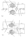
- Figure 1 shows an electronic setup for a DSC with power compensation.
- the DSC comprises at least two measurement positions, a first measurement or sample position S and a second measurement or reference position R.
- a sample or sample material can be placed on the sample position S and a reference material can be placed on the reference position R. Experiments on a sample can be performed with and without a reference material.
- the sample position S is in thermal contact with a sample heater 1 and a first compensation heater 2.
- the temperature at the sample position S is determined by a sensor comprising at least one thermocouple 3.
- the reference position R is in thermal contact with a reference heater 4 and a second compensation heater 5, which supplies an offset power arising from a constant offset voltage U off .
- the temperature at the reference position R is determined with a sensor comprising at least one thermocouple 8.
- the heaters 1, 2, 4, 5 are preferably designed as individual resistance heaters.
- the sample heater 1 and the reference heater 4 apply a temperature program to the respective measurement positions S, R and are part of a first control loop 6.
- This control loop 6 also comprises a PID controller 7.
- the temperature program is fed to the first control loop 6 as indicated by the temperature set points T set .
- the first compensation heater 2 is integrated in a second control loop 9, which also comprises a PID controller 10.
- the compensation voltage supplied to the sample position S gives rise to a compensation power and its magnitude is chosen in order to control any temperature difference ⁇ T between the sample position S and the reference position R to remain substantially zero. Therefore, the input to the second control loop 9 is the product of said temperature difference ⁇ T and the Seebeck constant of the thermopile ⁇ s .
- the control loops 6, 9 are connected with a main controller for controlling the DSC, which is not shown here.
- the compensation voltage applied to the first compensation heater 2 is raised and thus a compensation power is applied to said first compensation heater 2, which leads to an increase of the sample temperature T S in order to reduce the differential temperature ⁇ T to substantially zero again. If the sign of the differential temperature ⁇ T is positive, the compensation voltage applied to the second compensation heater 12 is raised in order to reduce the differential temperature ⁇ T to substantially zero.
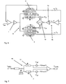
- FIG 3 shows another electronic setup for a DSC with dynamic compensation without compensation heaters.
- Each measurement position S, R is equipped with a main heater 1, 4 and at least one thermocouple 3, 8 as already described in Figure 2 .
- the main heaters 1, 4 are on one hand controlled by a first control loop 16, which supplies a temperature program T set to the measurement position S, R, and on the other hand by a second control loop 17, which comprises similar parts as the one described in Figure 2 . Due to a differential temperature ⁇ T determined from the thermocouple 3, 8 an extra heating power is supplied to either the sample position S or the reference position R through the second control loop 17. This extra heating power is electronically added to the main heating power delivered by the first control loop 16 to the respective main heater 1, 4.
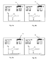
- Figures 4 and 5 the known power compensation principle is compared on a highly abstract level with the dynamic compensation according to the invention.
- Figure 4a shows the heating power distribution at the marked point of a melting curve of a polypropylene sample 14 subjected to a power compensated DSC experiment.
- Figure 4b shows the heating power distribution at the marked point of a crystallization curve of a polypropylene sample 14 subjected to a power compensated DSC.
- Figures 5a and 5b show the heating power distribution at the same point of a melting or respectively a crystallization curve of a polypropylene sample 14 subjected to a dynamic compensated DSC experiment.
- the dynamic compensation has the advantage that the compensation power as compensation voltage is only applied where and when it is needed, leading to the already mentioned advantages of increased headroom and an absence of an offset temperature.
- Figure 6 shows a further electronic setup for a DSC with dynamic compensation, which is similar to the setup of Figure 2 , but where a constant offset voltage U off is supplied to the first compensation heater 2 as well as to the second compensation heater 12.
- the offset voltage U off in a chip-calorimeter setup according to the invention can for example be about 0.5 V, which corresponds to about 50 ⁇ W of heating power based on a compensation heater with a resistance of about 5 k ⁇ .
- a thermal resistance of the order of 0.01 K/ ⁇ W, a typical magnitude in such a chip-calorimeter setup, will result in a very small offset temperature of only about 0.5°C.
- the exact amount for the offset voltage U off depends e. g. on the quality of the PID controller, the setup, etc.
- the offset voltage U off should be chosen in such a way that it is high enough to prevent artifacts without adding a significant temperature offset to the baseline.
- the data acquisition has to be adapted.
- the compensation power is acquired by measuring the voltage across and the current through the compensation heater.
- the dynamic compensation where the heating power is alternatively delivered to the two measurement positions, an extraction of individual signals, such as compensation voltage and compensation current, at one fixed point in the circuit is no longer possible.
- the data acquisition for a thermoanalytical instrument with a first and a second compensation heater comprises: Measuring the voltage U comp differentially across both compensation heaters and measuring the current I comp additively as the sum of the compensation heaters currents.
- this is schematically shown in the circuit diagram of Figure 7 showing the second control loop 15 of Figure 6 in more detail.
- the net compensation power P comp is the signal of interest.
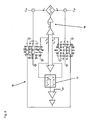
- Figure 8 shows an electronic setup of a further DSC with dynamic compensation, wherein interference between a first control loop 18 and a second control loop 19 is prevented by introducing switching means 20.
- the same decision criterion being used to activate the appropriate compensation heater 2, 12 on measurement positions R or S is also fed into the first control loop 18 via the switching means 20, which controls the temperature T S , T R to be used for controlling said first loop 18.
- T S temperature
- T R temperature
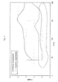
- Figure 9 shows comparative experiments on the cold crystallization of polyamide 6 subjected to DSC with dynamic compensation and a heating rate of 50 °C/s.
- the solid line graph represents a measurement without an additional compensation voltage offset U off and the dotted line graph a measurement with an additional compensation voltage U off applied to both compensation heaters 2, 12. It is evident from Figure 9 that the artifacts present around a power of 0 mW in the solid line graph do not appear in the dotted line graph, thereby showing the advantages of applying said additional compensation voltage offset U' off .
- the principle of dynamic compensation is especially useful for chip type differential scanning instruments but could also be adapted to other thermoanalytical instruments which so far utilize the power compensation principle.
Landscapes
- Chemical & Material Sciences (AREA)
- Physics & Mathematics (AREA)
- General Physics & Mathematics (AREA)
- Life Sciences & Earth Sciences (AREA)
- Combustion & Propulsion (AREA)
- Health & Medical Sciences (AREA)
- Analytical Chemistry (AREA)
- Biochemistry (AREA)
- General Health & Medical Sciences (AREA)
- Engineering & Computer Science (AREA)
- Immunology (AREA)
- Pathology (AREA)
- Chemical Kinetics & Catalysis (AREA)
- Investigating Or Analyzing Materials Using Thermal Means (AREA)
Claims (22)
- Thermoanalytisches Gerät, insbesondere ein Differenz-Scanning-Kalorimeter, umfassend eine erste Messposition (S), eine zweite Messposition (R), Mittel zum Einstellen eines vorgegebenen Temperaturprogramms von Temperatur-Zeit-Nennwerten, eine erste Heizung (1), die der ersten Messposition (S) zugeordnet ist, eine zweite Heizung (4), die der zweiten Messposition (R) zugeordnet ist, einen ersten Messfühler (3) zum Messen einer ersten Temperatur an der ersten Messposition (S), einen zweiten Messfühler (8) zum Messen einer zweiten Temperatur an der zweiten Messposition (R), und ferner umfassend einen Regler zum derartigen Regeln einer Heizleistung der ersten Heizung (1), dass bewirkt ist, dass die gemessene erste Temperatur im Wesentlichen dem Temperaturprogramm folgt, und zusätzlich zum derartigen Regeln der ersten und zweiten Heizung (1, 4), dass im Wesentlichen bewirkt wird, dass jegliche Differenz zwischen der ersten und zweiten gemessenen Temperatur Null wird, dadurch gekennzeichnet, dass der Regler Mittel zum Ermitteln (13) umfasst, welche der ersten und zweiten Temperatur niedriger ist, und der Heizung (1, 4) eine zusätzliche Leistung zuführt, die der Messposition mit der niedrigeren gemessenen Temperatur zugeordnet ist.
- Thermoanalytisches Gerät nach Anspruch 1, wobei das Gerät ferner eine erste Kompensationsheizung (2), die der ersten Messposition (S) zugeordnet ist, und eine zweite Kompensationsheizung (12) umfasst, die der zweiten Messposition (R) zugeordnet ist, wobei der Regler Mittel zum Ermitteln (13) umfasst, welche der ersten und zweiten Temperatur niedriger ist, und der Kompensationsheizung (2, 12) eine zusätzliche Leistung zuführt, die der Messposition mit der niedrigeren gemessenen Temperatur zugeordnet ist.
- Thermoanalytisches Gerät nach einem der Ansprüche 1 oder 2, wobei der Regler einen ersten Regelkreis (6, 16, 18) zum Regeln der Anwendung des Temperaturprogramms und einen zweiten Regelkreis (11, 15, 17) zum Regeln der Kompensation der Differenztemperatur zwischen der ersten und der zweiten Messposition (S, R) umfasst.
- Thermoanalytisches Gerät nach einem der Ansprüche 1 bis 3, wobei der Regler zumindest einen PID-Regler (7, 10) umfasst.
- Thermoanalytisches Gerät nach einem der Ansprüche 1 bis 3, wobei der Regler ein Fuzzyregelsystem umfasst.
- Thermoanalytisches Gerät nach einem der Ansprüche 1 bis 5, wobei jeder Messfühler (3, 8) eine Thermosäulenanordnung mit zumindest einem Thermoelement umfasst.
- Thermoanalytisches Gerät nach einem der Ansprüche 1 bis 6, wobei die Messpositionen (S, R) auf einer gemeinsamen Halterung angeordnet sind, oder wobei jede Messposition (S, R) auf einer separaten Halterung angeordnet ist.
- Thermoanalytisches Gerät nach einem der Ansprüche 1 bis 7, wobei das Gerät mehrere Paare erster und zweiter Messpositionen (S, R) umfasst.
- Thermoanalytisches Gerät nach einem der Ansprüche 1 bis 8, wobei der zweite Regelkreis ferner Begrenzungsmittel der Zufuhr der zusätzlichen Leistung umfasst, sodass die zusätzliche Leistung zu jedem Zeitpunkt nur einer der Heizungen (1, 4) oder Kompensationsheizungen (2, 12) zugeführt wird.
- Thermoanalytisches Gerät nach Anspruch 9, wobei die Begrenzungsmittel einen Spannungsfolger und eine Diode für jede Heizung oder Kompensationsheizung umfassen, wobei die Dioden gegenläufig zum jeweiligen Spannungsfolger ausgerichtet sind.
- Thermoanalytisches Gerät nach einem der Ansprüche 1 bis 10, wobei eine Eingangsleistung, die in den zweiten Regelkreis eingespeist ist, im Wesentlichen proportional zu einer Spannung ist, die die Heizung oder Kompensationsheizung erfordert und die mit der zusätzlichen Leistung zugeführt ist.
- Thermoanalytisches Gerät nach Anspruch 11, wobei der zweite Regelkreis einen Quadratwurzelschaltkreis umfasst.
- Thermoanalytisches Gerät nach einem der Ansprüche 2 bis 10, wobei das Gerät ferner Mittel zum Anlegen einer individuellen Offsetspannung (U'off) an jede Kompensationsheizung (2, 12) umfasst.
- Thermoanalytisches Gerät nach einem der Ansprüche 2 bis 13, wobei der erste und der zweite Regelkreis (18, 19) unterschiedliche Zeitkonstanten aufweisen.
- Thermoanalytisches Gerät nach einem der Ansprüche 2 bis 14, wobei der erste und zweite Regelkreis (19) Schaltmittel (20) zum Regeln der Temperatur umfassen, die in den ersten Regelkreis (18) eingegeben ist, der umgekehrt mit der Kompensationsheizung (2, 12) verbunden ist, welches von dem zweiten Regelkreis (19) aktiviert wird.
- Thermoanalytisches Gerät nach einem der Ansprüche 1 bis 15, wobei das Kalorimeter ein Chip-Differenz-Scanning-Kalorimeter ist.
- Verfahren zum Regeln eines thermoanalytischen Geräts, insbesondere eines Differenz-Scanning-Kalorimeters, das Gerät umfassend eine erste Messposition (S), eine zweite Messposition (R), Mittel zum Einstellen eines vorgegebenen Temperaturprogramms von Temperatur-Zeit-Nennwerten, eine erste Heizung (1), die der ersten Messposition (S) zugeordnet ist, eine zweite Heizung (4), die der zweiten Messposition (R) zugeordnet ist, einen ersten Messfühler (3), der eine erste Temperatur an der ersten Messposition (S) erfasst, einen zweiten Messfühler (8), der eine zweite Temperatur an der zweiten Messposition (R) erfasst, wobei ein Regler eine Heizleistung der ersten Heizung (1) derart regelt, dass bewirkt ist, dass die gemessene erste Temperatur im Wesentlichen dem Temperaturprogramm folgt, und wobei der Regler die erste und zweite Heizung (1, 4) zusätzlich derart regelt, dass im Wesentlichen bewirkt ist, dass jegliche Differenz zwischen der ersten und zweiten gemessenen Temperatur Null wird, dadurch gekennzeichnet, dass der Regler ermittelt, welche der ersten und zweiten Temperatur niedriger ist, und der Heizung (1, 4) eine zusätzliche Leistung zuführt, die der Messposition mit der niedrigeren gemessenen Temperatur zugeordnet ist.
- Verfahren nach Anspruch 17, wobei das thermoanalytische Gerät ferner eine erste Kompensationsheizung (2), die der ersten Messposition (S) zugeordnet ist, und eine zweite Kompensationsheizung (12) umfasst, die der zweiten Messposition (R) zugeordnet ist, und wobei der Regler ermittelt, welche der ersten und zweiten Temperatur niedriger ist, und der Kompensationsheizung (2, 12) eine zusätzliche Leistung zuführt, die der Messposition (S, R) mit der niedrigeren gemessenen Temperatur zugeordnet ist.
- Verfahren nach einem der Ansprüche 17 oder 18, wobei die Anwendung des Temperaturprogramms von einem ersten Regelkreis (6, 16, 18) geregelt wird und die Kompensation der Differenztemperatur von einem zweiten Regelkreis (12, 15, 17) geregelt wird.
- Verfahren nach Anspruch 19, wobei die Kompensation der Differenztemperatur ferner durch Begrenzungsmittel geregelt wird, die der zweite Regelkreis umfasst.
- Verfahren nach einem der Ansprüche 18 oder 20, wobei eine individuelle Offsetspannung (U'off) an jede Kompensationsheizung (2, 12) angelegt wird.
- Computerprogramm zum Steuern eines thermoanalytischen Geräts nach einem der Ansprüche 1 bis 16 mit einem Verfahren nach einem der Ansprüche 17 bis 21, dadurch gekennzeichnet, dass das Computerprogramm in einer Speichervorrichtung des Reglers des thermoanalytischen Geräts gespeichert ist.
Priority Applications (9)
| Application Number | Priority Date | Filing Date | Title |
|---|---|---|---|
| DE602008005427T DE602008005427D1 (de) | 2008-06-13 | 2008-06-13 | Wärmeanalyseinstrument mit dynamischer Leistungskompensation |
| EP08158196A EP2133690B1 (de) | 2008-06-13 | 2008-06-13 | Wärmeanalyseinstrument mit dynamischer Leistungskompensation |
| AT08158196T ATE501433T1 (de) | 2008-06-13 | 2008-06-13 | Wärmeanalyseinstrument mit dynamischer leistungskompensation |
| JP2009116516A JP5495616B2 (ja) | 2008-06-13 | 2009-05-13 | 熱分析装置 |
| US12/466,068 US8746966B2 (en) | 2008-06-13 | 2009-05-14 | Thermoanalytical instrument |
| CNA2009101492962A CN101603933A (zh) | 2008-06-13 | 2009-06-12 | 热分析仪器 |
| CN201510087065.9A CN104749216B (zh) | 2008-06-13 | 2009-06-12 | 热分析仪器 |
| US14/260,550 US20140233601A1 (en) | 2008-06-13 | 2014-04-24 | Thermoanalytical instrument |
| US15/445,316 US20170167926A1 (en) | 2008-06-13 | 2017-02-28 | Thermoanalytical instrument |
Applications Claiming Priority (1)
| Application Number | Priority Date | Filing Date | Title |
|---|---|---|---|
| EP08158196A EP2133690B1 (de) | 2008-06-13 | 2008-06-13 | Wärmeanalyseinstrument mit dynamischer Leistungskompensation |
Publications (2)
| Publication Number | Publication Date |
|---|---|
| EP2133690A1 EP2133690A1 (de) | 2009-12-16 |
| EP2133690B1 true EP2133690B1 (de) | 2011-03-09 |
Family
ID=40070926
Family Applications (1)
| Application Number | Title | Priority Date | Filing Date |
|---|---|---|---|
| EP08158196A Active EP2133690B1 (de) | 2008-06-13 | 2008-06-13 | Wärmeanalyseinstrument mit dynamischer Leistungskompensation |
Country Status (6)
| Country | Link |
|---|---|
| US (3) | US8746966B2 (de) |
| EP (1) | EP2133690B1 (de) |
| JP (1) | JP5495616B2 (de) |
| CN (2) | CN101603933A (de) |
| AT (1) | ATE501433T1 (de) |
| DE (1) | DE602008005427D1 (de) |
Families Citing this family (14)
| Publication number | Priority date | Publication date | Assignee | Title |
|---|---|---|---|---|
| JP2010016318A (ja) * | 2008-07-07 | 2010-01-21 | Canon Inc | 温度制御装置、露光システムおよびデバイス製造方法 |
| EP2214005B1 (de) * | 2009-02-03 | 2019-09-18 | Mettler-Toledo GmbH | Thermoanalysegerät |
| US8926172B2 (en) * | 2009-07-07 | 2015-01-06 | Frank Leu Wu | Differential adiabatic compensation calorimeter and methods of operation |
| KR101853882B1 (ko) * | 2011-01-10 | 2018-05-02 | 삼성전자주식회사 | 생체물질 검사장치 및 그 제어방법 |
| ES2763444T3 (es) * | 2011-10-19 | 2020-05-28 | Connectivity Systems Inc | Procedimiento de medición indirecta de temperatura de alimentos |
| CN102749352B (zh) * | 2012-07-23 | 2014-05-07 | 董洪标 | 单组元差分扫描量热方法 |
| US9334950B2 (en) * | 2013-03-11 | 2016-05-10 | Dana Automotive Systems Group, Llc | Differential carrier electronics package |
| JP6398807B2 (ja) | 2015-03-12 | 2018-10-03 | オムロン株式会社 | 温度差測定装置 |
| EP3396392B1 (de) | 2017-04-26 | 2020-11-04 | ElectDis AB | Vorrichtung und verfahren zur bestimmung eines leistungswerts eines ziels |
| CN107389206B (zh) * | 2017-06-12 | 2019-12-31 | 上海烨映电子技术有限公司 | 一种热电堆传感器及其控制方法 |
| CN109556987B (zh) * | 2018-11-27 | 2021-04-13 | 西安近代化学研究所 | 火炸药样品热分析过程中量热曲线基线位移的处理方法 |
| CN112089562B (zh) * | 2020-09-23 | 2021-06-29 | 郑州迪生仪器仪表有限公司 | 婴儿培养箱温度标定及测量方法 |
| CN114623946A (zh) * | 2022-03-11 | 2022-06-14 | 苏州热工研究院有限公司 | 一种热电势探头 |
| CN114610097B (zh) * | 2022-03-22 | 2023-09-15 | 青岛海尔生物医疗股份有限公司 | Pid参数自整定的温度控制的方法及装置、保温箱 |
Family Cites Families (35)
| Publication number | Priority date | Publication date | Assignee | Title |
|---|---|---|---|---|
| US3263484A (en) * | 1962-04-04 | 1966-08-02 | Perkin Elmer Corp | Differential microcalorimeter |
| US3747396A (en) * | 1971-07-09 | 1973-07-24 | Perkin Elmer Corp | Linearizing circuit for a ramp generator in a differential scanning calorimeter |
| US3795825A (en) * | 1973-02-28 | 1974-03-05 | Du Pont | Automatic gain compensation circuit |
| US3995485A (en) * | 1975-10-20 | 1976-12-07 | The United States Of America As Represented By The United States Energy Research And Development Administration | Dry, portable calorimeter for nondestructive measurement of the activity of nuclear fuel |
| US4255961A (en) * | 1978-10-17 | 1981-03-17 | University Of Va. Alumni Patents Foundation | Differential calorimeter based on the heat leak principle |
| SU1067375A1 (ru) * | 1982-02-02 | 1984-01-15 | Институт технической теплофизики АН УССР | Дифференциальный микрокалориметр |
| DE3517693A1 (de) * | 1985-05-14 | 1986-11-20 | Bodenseewerk Perkin-Elmer & Co GmbH, 7770 Überlingen | Verfahren und vorrichtung zur dynamischen-leistungs-differenz-kalorimetrie |
| DE3529489A1 (de) * | 1985-08-16 | 1987-02-26 | Max Planck Gesellschaft | Verfahren und einrichtung zum bestimmen der waermekapazitaet einer probe |
| US5439291C1 (en) * | 1992-03-02 | 2002-04-16 | Ta Instr Inc | Method and apparatus for ac differential thermal analysis |
| US5711604A (en) * | 1993-12-14 | 1998-01-27 | Seiko Instruments Inc. | Method for measuring the coefficient of heat conductivity of a sample |
| US5965606A (en) * | 1995-12-29 | 1999-10-12 | Allergan Sales, Inc. | Methods of treatment with compounds having RAR.sub.α receptor specific or selective activity |
| JP2002181751A (ja) * | 2000-12-13 | 2002-06-26 | Seiko Instruments Inc | 示差走査熱量計 |
| US5672289A (en) * | 1996-01-11 | 1997-09-30 | The Perkin-Elmer Corporation | Heater control circuit |
| US5813763A (en) * | 1996-10-11 | 1998-09-29 | Microcal Incorporated | Ultrasensitive differential microcalorimeter |
| US5973299A (en) * | 1996-11-01 | 1999-10-26 | Ta Instruments, Inc. | System and method for heater control for evaporation of cryogenic fluids for cooling scientific instruments |
| JP3377162B2 (ja) * | 1997-01-17 | 2003-02-17 | 株式会社リコー | 熱分析装置およびその計測方法 |
| US6079873A (en) * | 1997-10-20 | 2000-06-27 | The United States Of America As Represented By The Secretary Of Commerce | Micron-scale differential scanning calorimeter on a chip |
| JP3434694B2 (ja) * | 1997-12-01 | 2003-08-11 | セイコーインスツルメンツ株式会社 | 示差走査熱量計 |
| AU750929B2 (en) * | 1997-12-02 | 2002-08-01 | Allan L Smith | Apparatus and method for simultaneous measurement of mass and heat flow changes |
| US6572263B1 (en) * | 1998-04-14 | 2003-06-03 | Westinghouse Savannah River Company | Dry calorimeter |
| EP1132733B1 (de) * | 2000-02-03 | 2005-12-14 | Mettler-Toledo GmbH | Modulationsverfahren und Vorrichtung für die Thermoanalyse eines Materials |
| US6428203B1 (en) * | 2000-03-23 | 2002-08-06 | Ta Instruments, Inc. | Power compensation differential scanning calorimeter |
| JP2001305086A (ja) * | 2000-04-26 | 2001-10-31 | Seiko Instruments Inc | 熱分析装置 |
| US6648504B2 (en) * | 2002-03-01 | 2003-11-18 | Waters Investment Limited | System and method for calibrating contact thermal resistances in differential scanning calorimeters |
| DE50308067D1 (de) | 2003-07-04 | 2007-10-11 | Mettler Toledo Ag | Verfahren und Vorrichtung zur Stoffuntersuchung |
| US7371006B2 (en) * | 2004-02-10 | 2008-05-13 | Perkinelmer Las, Inc. | Differential scanning calorimeter (DSC) with temperature controlled furnace |
| CN100394168C (zh) | 2004-08-27 | 2008-06-11 | 南京大学 | 液氮气化扫描量热法及液氮气化扫描量热仪 |
| JP2006105935A (ja) * | 2004-10-08 | 2006-04-20 | Tokyo Institute Of Technology | 微小熱分析用プローブおよび微小熱分析装置ならびに微小熱分析方法 |
| EP1890138A1 (de) * | 2006-08-15 | 2008-02-20 | Eidgenössische Technische Hochschule Zürich | Bestimmung von spezifischer Wärmeleistung |
| US7578613B2 (en) * | 2006-09-14 | 2009-08-25 | Waters Investments Limited | Modulated differential scanning calorimeter solvent loss calibration apparatus and method |
| FR2925163B1 (fr) * | 2007-12-12 | 2010-02-26 | Centre Nat Rech Scient | Procede et appareil d'analyse thermique |
| EP2133676B1 (de) * | 2008-06-13 | 2013-03-13 | Mettler-Toledo AG | Kalorimetrisches Verfahren |
| EP2214005B1 (de) * | 2009-02-03 | 2019-09-18 | Mettler-Toledo GmbH | Thermoanalysegerät |
| EP2502057B1 (de) * | 2009-11-20 | 2020-01-01 | Netzsch Gerätebau GmbH | System und verfahren zur thermischen analyse |
| US10168292B2 (en) * | 2012-03-22 | 2019-01-01 | California Institute Of Technology | Nanoscale calorimeter on chip and related methods and devices |
-
2008
- 2008-06-13 DE DE602008005427T patent/DE602008005427D1/de active Active
- 2008-06-13 EP EP08158196A patent/EP2133690B1/de active Active
- 2008-06-13 AT AT08158196T patent/ATE501433T1/de not_active IP Right Cessation
-
2009
- 2009-05-13 JP JP2009116516A patent/JP5495616B2/ja active Active
- 2009-05-14 US US12/466,068 patent/US8746966B2/en active Active
- 2009-06-12 CN CNA2009101492962A patent/CN101603933A/zh active Pending
- 2009-06-12 CN CN201510087065.9A patent/CN104749216B/zh active Active
-
2014
- 2014-04-24 US US14/260,550 patent/US20140233601A1/en not_active Abandoned
-
2017
- 2017-02-28 US US15/445,316 patent/US20170167926A1/en not_active Abandoned
Also Published As
| Publication number | Publication date |
|---|---|
| CN101603933A (zh) | 2009-12-16 |
| CN104749216B (zh) | 2017-10-13 |
| EP2133690A1 (de) | 2009-12-16 |
| DE602008005427D1 (de) | 2011-04-21 |
| US20140233601A1 (en) | 2014-08-21 |
| JP2010002412A (ja) | 2010-01-07 |
| US20170167926A1 (en) | 2017-06-15 |
| JP5495616B2 (ja) | 2014-05-21 |
| US8746966B2 (en) | 2014-06-10 |
| CN104749216A (zh) | 2015-07-01 |
| ATE501433T1 (de) | 2011-03-15 |
| US20090310644A1 (en) | 2009-12-17 |
Similar Documents
| Publication | Publication Date | Title |
|---|---|---|
| EP2133690B1 (de) | Wärmeanalyseinstrument mit dynamischer Leistungskompensation | |
| Zhuravlev et al. | Fast scanning power compensated differential scanning nano-calorimeter: 1. The device | |
| CN107014859B (zh) | 热分析仪 | |
| US7626144B2 (en) | Method and apparatus for rapid temperature changes | |
| Adamovsky et al. | Scanning microcalorimetry at high cooling rate | |
| Adamovsky et al. | Ultra-fast isothermal calorimetry using thin film sensors | |
| CN202267663U (zh) | 量热计及其控制系统 | |
| Sultan et al. | Thermal conductivity of micromachined low-stress silicon-nitride beams from 77 to 325 K | |
| US7407325B2 (en) | Method and apparatus for measuring thermophysical properties | |
| JP5395807B2 (ja) | 熱分析方法および装置 | |
| US11402250B2 (en) | Liquid level meter, vaporizer equipped with the same, and liquid level detection method | |
| US6632015B2 (en) | Thermal analysis apparatus | |
| EP0962763A1 (de) | Differentialscanningkalorimeter | |
| Inaba | Nano-watt stabilized DSC and ITS applications | |
| Merzlyakov | Integrated circuit thermopile as a new type of temperature modulated calorimeter | |
| JP3687030B2 (ja) | 微小表面温度分布計測法およびそのための装置 | |
| Merzlyakov | Method of rapid (100 000 K s− 1) controlled cooling and heating of thin samples | |
| Harasztosi et al. | Microcalorimeter development and calibration based on a twin micro-heater platform | |
| Harasztosi et al. | Temperature Calibration of Twin Micro-heater Based Microcalorimeter | |
| JP2007285849A (ja) | ガス濃度検出装置 | |
| JPH07248304A (ja) | 熱伝導率計 | |
| Mehta et al. | High resolution calorimetry on μmole samples of 4He near Tλ | |
| Märtson et al. | Development of a faster hot-stage for microscopy studies of polymer crystallization | |
| Hakala et al. | A hybrid method for calorimetry with subnanoliter samples using Schottky junctions | |
| Tagliati et al. | Membrane-based calorimetry for studies of sub-microgram samples |
Legal Events
| Date | Code | Title | Description |
|---|---|---|---|
| PUAI | Public reference made under article 153(3) epc to a published international application that has entered the european phase |
Free format text: ORIGINAL CODE: 0009012 |
|
| AK | Designated contracting states |
Kind code of ref document: A1 Designated state(s): AT BE BG CH CY CZ DE DK EE ES FI FR GB GR HR HU IE IS IT LI LT LU LV MC MT NL NO PL PT RO SE SI SK TR |
|
| AX | Request for extension of the european patent |
Extension state: AL BA MK RS |
|
| 17P | Request for examination filed |
Effective date: 20100119 |
|
| 17Q | First examination report despatched |
Effective date: 20100308 |
|
| AKX | Designation fees paid |
Designated state(s): AT BE BG CH CY CZ DE DK EE ES FI FR GB GR HR HU IE IS IT LI LT LU LV MC MT NL NO PL PT RO SE SI SK TR |
|
| GRAP | Despatch of communication of intention to grant a patent |
Free format text: ORIGINAL CODE: EPIDOSNIGR1 |
|
| GRAS | Grant fee paid |
Free format text: ORIGINAL CODE: EPIDOSNIGR3 |
|
| GRAA | (expected) grant |
Free format text: ORIGINAL CODE: 0009210 |
|
| AK | Designated contracting states |
Kind code of ref document: B1 Designated state(s): AT BE BG CH CY CZ DE DK EE ES FI FR GB GR HR HU IE IS IT LI LT LU LV MC MT NL NO PL PT RO SE SI SK TR |
|
| REG | Reference to a national code |
Ref country code: GB Ref legal event code: FG4D |
|
| REG | Reference to a national code |
Ref country code: CH Ref legal event code: EP |
|
| REG | Reference to a national code |
Ref country code: IE Ref legal event code: FG4D |
|
| REF | Corresponds to: |
Ref document number: 602008005427 Country of ref document: DE Date of ref document: 20110421 Kind code of ref document: P |
|
| REG | Reference to a national code |
Ref country code: DE Ref legal event code: R096 Ref document number: 602008005427 Country of ref document: DE Effective date: 20110421 |
|
| REG | Reference to a national code |
Ref country code: NL Ref legal event code: T3 |
|
| PG25 | Lapsed in a contracting state [announced via postgrant information from national office to epo] |
Ref country code: HR Free format text: LAPSE BECAUSE OF FAILURE TO SUBMIT A TRANSLATION OF THE DESCRIPTION OR TO PAY THE FEE WITHIN THE PRESCRIBED TIME-LIMIT Effective date: 20110309 Ref country code: ES Free format text: LAPSE BECAUSE OF FAILURE TO SUBMIT A TRANSLATION OF THE DESCRIPTION OR TO PAY THE FEE WITHIN THE PRESCRIBED TIME-LIMIT Effective date: 20110620 Ref country code: GR Free format text: LAPSE BECAUSE OF FAILURE TO SUBMIT A TRANSLATION OF THE DESCRIPTION OR TO PAY THE FEE WITHIN THE PRESCRIBED TIME-LIMIT Effective date: 20110610 Ref country code: LV Free format text: LAPSE BECAUSE OF FAILURE TO SUBMIT A TRANSLATION OF THE DESCRIPTION OR TO PAY THE FEE WITHIN THE PRESCRIBED TIME-LIMIT Effective date: 20110309 Ref country code: SE Free format text: LAPSE BECAUSE OF FAILURE TO SUBMIT A TRANSLATION OF THE DESCRIPTION OR TO PAY THE FEE WITHIN THE PRESCRIBED TIME-LIMIT Effective date: 20110309 Ref country code: NO Free format text: LAPSE BECAUSE OF FAILURE TO SUBMIT A TRANSLATION OF THE DESCRIPTION OR TO PAY THE FEE WITHIN THE PRESCRIBED TIME-LIMIT Effective date: 20110609 Ref country code: LT Free format text: LAPSE BECAUSE OF FAILURE TO SUBMIT A TRANSLATION OF THE DESCRIPTION OR TO PAY THE FEE WITHIN THE PRESCRIBED TIME-LIMIT Effective date: 20110309 |
|
| LTIE | Lt: invalidation of european patent or patent extension |
Effective date: 20110309 |
|
| PG25 | Lapsed in a contracting state [announced via postgrant information from national office to epo] |
Ref country code: AT Free format text: LAPSE BECAUSE OF FAILURE TO SUBMIT A TRANSLATION OF THE DESCRIPTION OR TO PAY THE FEE WITHIN THE PRESCRIBED TIME-LIMIT Effective date: 20110309 Ref country code: BG Free format text: LAPSE BECAUSE OF FAILURE TO SUBMIT A TRANSLATION OF THE DESCRIPTION OR TO PAY THE FEE WITHIN THE PRESCRIBED TIME-LIMIT Effective date: 20110609 Ref country code: SI Free format text: LAPSE BECAUSE OF FAILURE TO SUBMIT A TRANSLATION OF THE DESCRIPTION OR TO PAY THE FEE WITHIN THE PRESCRIBED TIME-LIMIT Effective date: 20110309 Ref country code: CY Free format text: LAPSE BECAUSE OF FAILURE TO SUBMIT A TRANSLATION OF THE DESCRIPTION OR TO PAY THE FEE WITHIN THE PRESCRIBED TIME-LIMIT Effective date: 20110309 Ref country code: FI Free format text: LAPSE BECAUSE OF FAILURE TO SUBMIT A TRANSLATION OF THE DESCRIPTION OR TO PAY THE FEE WITHIN THE PRESCRIBED TIME-LIMIT Effective date: 20110309 |
|
| PG25 | Lapsed in a contracting state [announced via postgrant information from national office to epo] |
Ref country code: BE Free format text: LAPSE BECAUSE OF FAILURE TO SUBMIT A TRANSLATION OF THE DESCRIPTION OR TO PAY THE FEE WITHIN THE PRESCRIBED TIME-LIMIT Effective date: 20110309 |
|
| PG25 | Lapsed in a contracting state [announced via postgrant information from national office to epo] |
Ref country code: EE Free format text: LAPSE BECAUSE OF FAILURE TO SUBMIT A TRANSLATION OF THE DESCRIPTION OR TO PAY THE FEE WITHIN THE PRESCRIBED TIME-LIMIT Effective date: 20110309 Ref country code: PT Free format text: LAPSE BECAUSE OF FAILURE TO SUBMIT A TRANSLATION OF THE DESCRIPTION OR TO PAY THE FEE WITHIN THE PRESCRIBED TIME-LIMIT Effective date: 20110711 |
|
| PG25 | Lapsed in a contracting state [announced via postgrant information from national office to epo] |
Ref country code: CZ Free format text: LAPSE BECAUSE OF FAILURE TO SUBMIT A TRANSLATION OF THE DESCRIPTION OR TO PAY THE FEE WITHIN THE PRESCRIBED TIME-LIMIT Effective date: 20110309 Ref country code: SK Free format text: LAPSE BECAUSE OF FAILURE TO SUBMIT A TRANSLATION OF THE DESCRIPTION OR TO PAY THE FEE WITHIN THE PRESCRIBED TIME-LIMIT Effective date: 20110309 Ref country code: IS Free format text: LAPSE BECAUSE OF FAILURE TO SUBMIT A TRANSLATION OF THE DESCRIPTION OR TO PAY THE FEE WITHIN THE PRESCRIBED TIME-LIMIT Effective date: 20110709 Ref country code: RO Free format text: LAPSE BECAUSE OF FAILURE TO SUBMIT A TRANSLATION OF THE DESCRIPTION OR TO PAY THE FEE WITHIN THE PRESCRIBED TIME-LIMIT Effective date: 20110309 |
|
| PG25 | Lapsed in a contracting state [announced via postgrant information from national office to epo] |
Ref country code: MT Free format text: LAPSE BECAUSE OF FAILURE TO SUBMIT A TRANSLATION OF THE DESCRIPTION OR TO PAY THE FEE WITHIN THE PRESCRIBED TIME-LIMIT Effective date: 20110309 |
|
| PLBE | No opposition filed within time limit |
Free format text: ORIGINAL CODE: 0009261 |
|
| STAA | Information on the status of an ep patent application or granted ep patent |
Free format text: STATUS: NO OPPOSITION FILED WITHIN TIME LIMIT |
|
| 26N | No opposition filed |
Effective date: 20111212 |
|
| PG25 | Lapsed in a contracting state [announced via postgrant information from national office to epo] |
Ref country code: PL Free format text: LAPSE BECAUSE OF FAILURE TO SUBMIT A TRANSLATION OF THE DESCRIPTION OR TO PAY THE FEE WITHIN THE PRESCRIBED TIME-LIMIT Effective date: 20110309 Ref country code: DK Free format text: LAPSE BECAUSE OF FAILURE TO SUBMIT A TRANSLATION OF THE DESCRIPTION OR TO PAY THE FEE WITHIN THE PRESCRIBED TIME-LIMIT Effective date: 20110309 |
|
| REG | Reference to a national code |
Ref country code: IE Ref legal event code: MM4A |
|
| REG | Reference to a national code |
Ref country code: DE Ref legal event code: R097 Ref document number: 602008005427 Country of ref document: DE Effective date: 20111212 |
|
| PG25 | Lapsed in a contracting state [announced via postgrant information from national office to epo] |
Ref country code: IE Free format text: LAPSE BECAUSE OF NON-PAYMENT OF DUE FEES Effective date: 20110613 |
|
| PG25 | Lapsed in a contracting state [announced via postgrant information from national office to epo] |
Ref country code: IT Free format text: LAPSE BECAUSE OF FAILURE TO SUBMIT A TRANSLATION OF THE DESCRIPTION OR TO PAY THE FEE WITHIN THE PRESCRIBED TIME-LIMIT Effective date: 20110309 |
|
| PG25 | Lapsed in a contracting state [announced via postgrant information from national office to epo] |
Ref country code: MC Free format text: LAPSE BECAUSE OF NON-PAYMENT OF DUE FEES Effective date: 20110630 |
|
| PG25 | Lapsed in a contracting state [announced via postgrant information from national office to epo] |
Ref country code: LU Free format text: LAPSE BECAUSE OF NON-PAYMENT OF DUE FEES Effective date: 20110613 |
|
| PG25 | Lapsed in a contracting state [announced via postgrant information from national office to epo] |
Ref country code: TR Free format text: LAPSE BECAUSE OF FAILURE TO SUBMIT A TRANSLATION OF THE DESCRIPTION OR TO PAY THE FEE WITHIN THE PRESCRIBED TIME-LIMIT Effective date: 20110309 |
|
| PG25 | Lapsed in a contracting state [announced via postgrant information from national office to epo] |
Ref country code: HU Free format text: LAPSE BECAUSE OF FAILURE TO SUBMIT A TRANSLATION OF THE DESCRIPTION OR TO PAY THE FEE WITHIN THE PRESCRIBED TIME-LIMIT Effective date: 20110309 |
|
| REG | Reference to a national code |
Ref country code: CH Ref legal event code: PCOW Free format text: NEW ADDRESS: IM LANGACHER 44, 8606 GREIFENSEE (CH) |
|
| REG | Reference to a national code |
Ref country code: CH Ref legal event code: PFA Owner name: METTLER-TOLEDO GMBH, CH Free format text: FORMER OWNER: METTLER-TOLEDO AG, CH |
|
| REG | Reference to a national code |
Ref country code: FR Ref legal event code: PLFP Year of fee payment: 9 |
|
| REG | Reference to a national code |
Ref country code: FR Ref legal event code: PLFP Year of fee payment: 10 |
|
| REG | Reference to a national code |
Ref country code: DE Ref legal event code: R081 Ref document number: 602008005427 Country of ref document: DE Owner name: METTLER-TOLEDO GMBH, CH Free format text: FORMER OWNER: METTLER-TOLEDO AG, GREIFENSEE, CH |
|
| REG | Reference to a national code |
Ref country code: NL Ref legal event code: PD Owner name: METTLER-TOLEDO GMBH; CH Free format text: DETAILS ASSIGNMENT: CHANGE OF OWNER(S), CHANGE OF LEGAL ENTITY; FORMER OWNER NAME: METTLER-TOLEDO AG Effective date: 20170830 |
|
| REG | Reference to a national code |
Ref country code: FR Ref legal event code: CJ Effective date: 20180409 |
|
| REG | Reference to a national code |
Ref country code: FR Ref legal event code: PLFP Year of fee payment: 11 |
|
| PGFP | Annual fee paid to national office [announced via postgrant information from national office to epo] |
Ref country code: FR Payment date: 20240625 Year of fee payment: 17 |
|
| PGFP | Annual fee paid to national office [announced via postgrant information from national office to epo] |
Ref country code: CH Payment date: 20240701 Year of fee payment: 17 |
|
| PGFP | Annual fee paid to national office [announced via postgrant information from national office to epo] |
Ref country code: DE Payment date: 20250602 Year of fee payment: 18 |
|
| PGFP | Annual fee paid to national office [announced via postgrant information from national office to epo] |
Ref country code: GB Payment date: 20250617 Year of fee payment: 18 |
|
| PGFP | Annual fee paid to national office [announced via postgrant information from national office to epo] |
Ref country code: NL Payment date: 20250624 Year of fee payment: 18 |