EP2133017B2 - Filterbeutel - Google Patents
Filterbeutel Download PDFInfo
- Publication number
- EP2133017B2 EP2133017B2 EP09160485.0A EP09160485A EP2133017B2 EP 2133017 B2 EP2133017 B2 EP 2133017B2 EP 09160485 A EP09160485 A EP 09160485A EP 2133017 B2 EP2133017 B2 EP 2133017B2
- Authority
- EP
- European Patent Office
- Prior art keywords
- filter
- layer
- bag according
- insert
- filter insert
- Prior art date
- Legal status (The legal status is an assumption and is not a legal conclusion. Google has not performed a legal analysis and makes no representation as to the accuracy of the status listed.)
- Active
Links
Images


Classifications
-
- A—HUMAN NECESSITIES
- A47—FURNITURE; DOMESTIC ARTICLES OR APPLIANCES; COFFEE MILLS; SPICE MILLS; SUCTION CLEANERS IN GENERAL
- A47L—DOMESTIC WASHING OR CLEANING; SUCTION CLEANERS IN GENERAL
- A47L9/00—Details or accessories of suction cleaners, e.g. mechanical means for controlling the suction or for effecting pulsating action; Storing devices specially adapted to suction cleaners or parts thereof; Carrying-vehicles specially adapted for suction cleaners
- A47L9/10—Filters; Dust separators; Dust removal; Automatic exchange of filters
- A47L9/14—Bags or the like; Rigid filtering receptacles; Attachment of, or closures for, bags or receptacles
-
- B—PERFORMING OPERATIONS; TRANSPORTING
- B01—PHYSICAL OR CHEMICAL PROCESSES OR APPARATUS IN GENERAL
- B01D—SEPARATION
- B01D39/00—Filtering material for liquid or gaseous fluids
- B01D39/14—Other self-supporting filtering material ; Other filtering material
- B01D39/16—Other self-supporting filtering material ; Other filtering material of organic material, e.g. synthetic fibres
- B01D39/1669—Cellular material
- B01D39/1676—Cellular material of synthetic origin
-
- B—PERFORMING OPERATIONS; TRANSPORTING
- B01—PHYSICAL OR CHEMICAL PROCESSES OR APPARATUS IN GENERAL
- B01D—SEPARATION
- B01D39/00—Filtering material for liquid or gaseous fluids
- B01D39/14—Other self-supporting filtering material ; Other filtering material
- B01D39/16—Other self-supporting filtering material ; Other filtering material of organic material, e.g. synthetic fibres
- B01D39/1692—Other shaped material, e.g. perforated or porous sheets
-
- B—PERFORMING OPERATIONS; TRANSPORTING
- B01—PHYSICAL OR CHEMICAL PROCESSES OR APPARATUS IN GENERAL
- B01D—SEPARATION
- B01D39/00—Filtering material for liquid or gaseous fluids
- B01D39/14—Other self-supporting filtering material ; Other filtering material
- B01D39/20—Other self-supporting filtering material ; Other filtering material of inorganic material, e.g. asbestos paper, metallic filtering material of non-woven wires
- B01D39/2003—Glass or glassy material
- B01D39/2017—Glass or glassy material the material being filamentary or fibrous
-
- B—PERFORMING OPERATIONS; TRANSPORTING
- B01—PHYSICAL OR CHEMICAL PROCESSES OR APPARATUS IN GENERAL
- B01D—SEPARATION
- B01D39/00—Filtering material for liquid or gaseous fluids
- B01D39/14—Other self-supporting filtering material ; Other filtering material
- B01D39/20—Other self-supporting filtering material ; Other filtering material of inorganic material, e.g. asbestos paper, metallic filtering material of non-woven wires
- B01D39/2068—Other inorganic materials, e.g. ceramics
- B01D39/2082—Other inorganic materials, e.g. ceramics the material being filamentary or fibrous
-
- B—PERFORMING OPERATIONS; TRANSPORTING
- B01—PHYSICAL OR CHEMICAL PROCESSES OR APPARATUS IN GENERAL
- B01D—SEPARATION
- B01D2239/00—Aspects relating to filtering material for liquid or gaseous fluids
- B01D2239/06—Filter cloth, e.g. knitted, woven non-woven; self-supported material
- B01D2239/065—More than one layer present in the filtering material
-
- Y—GENERAL TAGGING OF NEW TECHNOLOGICAL DEVELOPMENTS; GENERAL TAGGING OF CROSS-SECTIONAL TECHNOLOGIES SPANNING OVER SEVERAL SECTIONS OF THE IPC; TECHNICAL SUBJECTS COVERED BY FORMER USPC CROSS-REFERENCE ART COLLECTIONS [XRACs] AND DIGESTS
- Y10—TECHNICAL SUBJECTS COVERED BY FORMER USPC
- Y10S—TECHNICAL SUBJECTS COVERED BY FORMER USPC CROSS-REFERENCE ART COLLECTIONS [XRACs] AND DIGESTS
- Y10S15/00—Brushing, scrubbing, and general cleaning
- Y10S15/08—Dust bags and separators
-
- Y—GENERAL TAGGING OF NEW TECHNOLOGICAL DEVELOPMENTS; GENERAL TAGGING OF CROSS-SECTIONAL TECHNOLOGIES SPANNING OVER SEVERAL SECTIONS OF THE IPC; TECHNICAL SUBJECTS COVERED BY FORMER USPC CROSS-REFERENCE ART COLLECTIONS [XRACs] AND DIGESTS
- Y10—TECHNICAL SUBJECTS COVERED BY FORMER USPC
- Y10S—TECHNICAL SUBJECTS COVERED BY FORMER USPC CROSS-REFERENCE ART COLLECTIONS [XRACs] AND DIGESTS
- Y10S55/00—Gas separation
- Y10S55/02—Vacuum cleaner bags
Definitions
- the present invention relates to a filter bag, in particular for vacuum cleaners, with a first filter material layer with an inflow opening and a second filter material layer, which is connected at the edge to the first filter material layer to form an interior, in the interior one at least partially with the first and / or second Filter material layer connected planar multilayer filter insert is arranged.
- a vacuum cleaner bag in which an upper filter material layer is welded to the edge with a lower filter material layer.
- An inflow opening is formed on a filter material layer, with a cushion being provided on the side opposite the inflow opening which has adsorption material to avoid unpleasant smells. If such a vacuum cleaner bag is loaded with dust, the filter material layers are clogged with dust, so that there is a drop in the volume flow and thus a drop in the suction power.
- a filter bag In order to improve the dust holding capacity of a vacuum cleaner bag, the DE 20 2006 016 303 U a filter bag is known in which a partition is arranged in the interior of the bag, on which a part of the dust that is sucked in can settle. As a result, the filter material layers on the outer walls of the vacuum cleaner bag are less clogged with dust. Although a partition made of flat filter material can be integrated into the vacuum cleaner bag with limited effort during the manufacturing process, the dust storage capacity of a partition for subdividing the vacuum cleaner bag is limited.
- the DE 20 2008 003 248 U discloses a vacuum cleaner bag in which a deflector strip, a strip of material and a piece of material are provided in the interior.
- the strip of material is at least partially unconnected to the bag wall and can consist of an air-permeable material.
- the filter insert has at least two outer layers, between which a middle layer is provided for loading with dust.
- the dust-laden air can be blown into the filter insert during use, so that the dust can collect in the middle layer and is pre-filtered there. All dust that is deposited in the filter insert can no longer clog the outer filter material layers of the filter bag.
- the filter insert is initially filled with dust, so that the outer filter material layers clog less and thus the volume flow drop is small with the same suction power.
- the outer layer has at least one opening on the side facing the inflow opening for dust-laden air to flow into the middle layer.
- the filter insert has a middle layer which is surrounded on opposite sides by an outer layer of greater strength.
- the outer layers can, for example, have a tensile strength that is 50% higher than the middle layer, so that it is ensured that the outer layers are not accidentally damaged when the middle layer is loaded with dust.
- the force for detaching an outer layer from the middle layer or the other outer layer can be greater than 2N for a 20 mm wide specimen.
- the filter insert is formed from a multi-layer nonwoven.
- This non-woven fabric can be a non-woven fabric smoothed on both sides with a softer core, so that the voluminous, fluffy middle layer is used to store dust.
- the opening on the side of an outer layer facing the inflow opening can be formed by a predetermined breaking point which tears open during use.
- the filter insert can remain intact until use, the predetermined breaking point enabling the outer layer to be opened in a targeted manner on the side facing the inflow opening.
- several smaller openings can be formed in the outer layer, which allow the dust-laden air to flow into the filter insert. It is also possible to provide the outer layer on the side facing the inflow opening with punch-outs, slots or other openings which ensure a flow into the filter insert.
- the filter bag comprises a filter insert made of a spunbond, the outer sides of which are thermally solidified.
- the hardening of the outer layers can be done wet, chemically, thermally, mechanically, with needles or with a water jet.
- the outer layers can also have a perforated film or other sheet-like materials.
- the outer layers preferably have a greater air permeability than the filter material layers.
- the outer layers of the filter insert form a type of pre-filter, while the filter material layers have at least one layer that serves as a fine filter and can filter out very small particles.
- the middle layer can be at least three times, preferably at least five times as thick as an outer layer. Furthermore, the middle layer can have a thickness of more than 2 mm, preferably more than 4 mm.
- the filter insert can be fixed to at least one seam between the first and second filter material layers. This is because the two layers of filter material are connected to one another at least on one side, possibly also on all four sides, by a seam, preferably a weld seam. If the filter insert is also fixed at the same time during the production of this seam, no separate fastening process has to be carried out to fix the filter insert.
- the filter insert can preferably be fixed at three or four side seams between the first and second filter material layers.
- the filter insert is connected to the first material layer in an area adjacent to the inflow opening. This ensures that the filter insert is not only pressed onto a filter material layer by the incoming volume flow, but rather hangs loosely in the interior of the filter bag, since on one side there is a fixation on the first filter material layer adjacent to the inflow opening and on the opposite side a connection with a seam in the side area of the first and second filter material layer can be made. This means that the filter insert hangs loosely inside the filter bag.
- the filter insert can be designed as a continuous strip which is fixed at the end at a seam between the first and second filter material layer.
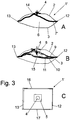
- a filter bag 1 comprises a first upper filter material layer 2 on which an inflow opening 4 is formed.
- the first filter material layer 2 is circumferentially connected to a second filter material layer 3, preferably via a weld seam.
- the filter material layers 2 and 3 can be formed from a multi-layer nonwoven fabric which has at least one fine filter layer, for example by a layer of meltblown.
- a holding plate 5 is provided around the inflow opening 4, by means of which the filter bag 1 can be fixed to a vacuum cleaner.
- An interior 6 is formed between the first filter material layer 2 and the second filter material layer, in which dust can collect during operation.
- a filter insert 7 is arranged in the interior 6, which rests over the entire surface of the second filter material layer 3 and is attached to the edge of the seam between the first filter material layer 2 and the second material layer 3.
- the filter insert 7 has at least one opening 8 on the side facing the inflow opening 4, which opening is formed in an outer layer 9 of the filter insert.
- the filter insert 7 has a filter layer 10 which is surrounded on opposite sides by an outer layer 9 or 11.
- the outer layers 9 and 11 have a higher strength than the thicker middle layer 10.
- the filter insert 7 is shown in section.
- a thicker middle layer 14 is surrounded by two outer layers 9 and 11.
- the middle layer 10 has a thickness of at least 2 mm, preferably 4 to 10 mm.
- the middle layer can consist of a soft, fluffy material, preferably a spunbonded nonwoven.
- the outer layers 9 and 11 are made of a material with greater strength than the middle layer, for example non-woven fabric can be used, which are consolidated.
- the filter insert 7 can be produced in that a spunbond material is heat-solidified by an embossing calender, so that only the surface of the spunbond is solidified by plasticizing and fusing of fibers, but the middle layer 10 remains soft and fluffy.
- a predetermined breaking point can also be provided on the outer layer 9, so that the predetermined breaking point breaks open during use and forms an opening 8 so that the filter insert 7 can be loaded with dust.
- a filter insert 7 ' is provided in an interior 6, which is fixed on a first side to a seam 12 in the connecting area of the first filter material layer 2 and the second filter material layer 3 and on an opposite side to a seam 13 of the first and second filter material layer 2 and 3 is set.
- the filter insert 7' additionally has a fastening point 14, for example a weld seam, which is arranged in a central area of the filter material layer 2, specifically in an area adjacent to the inflow opening 4. This ensures that the filter insert 7 'hangs loosely in the interior 6, so that the filter insert 7' can be flowed around with air on all sides.
- the filter insert 7 ' is shown in the filled state.
- the filter insert 7 ′ comprises an outer layer 9 on which one or more openings 8 are formed so that air flowing in through the inflow opening 4 can pass through the openings 8 and dust 15 can collect in the area of the middle layer 10.
- the filter insert 7 ' acts as a pre-filter, so that the filter material layers 2 and 3 are not clogged with dust so quickly.
- FIG 3C the inner area of the filter bag 1 'is shown in section, the seams 12, 13, 16 and 17 at which the first filter material layer 2 is connected to the second filter material layer 3, preferably by ultrasonic welding.
- the filter insert 7 ′ extends over the entire surface in the filter bag 1 ′ and is approximately the same size as one of the filter material layers 2 or 3.
- FIGS 4A to 4C a further embodiment of a filter bag 1 ′′ according to the invention is shown, a filter insert 7 ′′ in an interior 6 between a first filter material layer 2 and a second filter material layer 3.
- the filter insert 7 ′′ has a smaller size than one of the filter material layers 2 or 3, the filter insert 7 ′′ being fixed to a seam 12 between the first and second filter material layers 2 and 3. On the opposite side, the filter insert 7 ′′ is fixed to a seam 20 which is arranged adjacent to the inflow opening 4. The filter insert 7 ′′ is connected to the filter material layer 2 at the seam 20. As a result, the filter insert 7 ′′ hangs loosely in the interior 6, so that both outer layers 9 and 11 can be flushed with air.
- the filter insert 7 ′′ is significantly smaller than a filter material layer 2 or 3, as shown in FIG Figure 4C you can see. As a result, a high dust storage volume can be obtained, even if the use of material is lower.
- the air flow entering through the inflow opening 4 can flow through openings 8 in the outer layer 9 into the filter insert 7 ′′, so that dust 21 can collect in a middle layer 10 of the filter insert 7 ′′ and thus can no longer clog the filter material layers 2 and 3 .
- the filter insert 7, 7 ', 7 "serves as a kind of pre-filter, the outer layers 9 and 11 having a greater air permeability than the filter material layers 2 and 3.
- the shape of the filter insert 7 can be freely designed in wide areas, as long as the inflowing air can flow into the filter insert and dust settles in a middle layer 10.
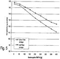
- FIG. 5 a diagram is shown in which the suction power is shown with regard to the filling of a vacuum cleaner bag.
- a first dust bag without a filter insert is inserted into a vacuum cleaner.
- the vacuum cleaner is operated with a certain power and as the vacuum cleaner bag is filled with dust, the suction volume flow is measured.
- the vacuum cleaner bag used consists of five-layer fleece material, one layer of spunbond 15 g / m 2 , one layer of volume fleece 55 g / m 2 , one layer of spunbond 15 g / m 2 , one layer of meltblown 25 g / m 2 and one layer of spunbond 25 g / m 2 ,
- a vacuum cleaner bag with the above materials was additionally provided with a filter insert on the underside of the bag in the interior, which is a partially solidified spunbond with a surface weight of approx. 60 g / m 2 and is welded to the seams of the filter bag on all four sides ( Figure 1A ).
- the filter insert can consist of a fleece smoothed on both sides with a softer core, or it can consist of two or more interconnected fleeces.
- Spunbonded nonwovens, spunbond, meltblow, carded nonwovens (wet, chemically, thermally, mechanically solidified by needling or water jet), foam rubber, perforated film, lattice fabric, glass or mineral wool or combinations thereof can be used as nonwovens.
- combinations of at least two air-permeable fleeces with a permeability of at least 100 1 / qxs can also be used for the filter insert, the fleeces being slightly connected to one another and the force to separate the two fleeces is greater than 2N for 20mm wide specimens.
- the outer nonwovens have a strength that is 50% higher than that of a medium nonwoven material.
Landscapes
- Chemical & Material Sciences (AREA)
- Chemical Kinetics & Catalysis (AREA)
- Life Sciences & Earth Sciences (AREA)
- Geology (AREA)
- Engineering & Computer Science (AREA)
- Ceramic Engineering (AREA)
- Inorganic Chemistry (AREA)
- Mechanical Engineering (AREA)
- Filters For Electric Vacuum Cleaners (AREA)
- Filtering Materials (AREA)
Description
- Die vorliegende Erfindung betrifft einen Filterbeutel, insbesondere für Staubsauger, mit einer ersten Filtermateriallage mit einer Einströmöffnung und einer zweiten Filtermateriallage, die randseitig mit der ersten Filtermateriallage zur Ausbildung eines Innenraumes verbunden ist, wobei in dem Innenraum eine zumindest teilweise mit der ersten und/oder zweiten Filtermateriallage verbundene flächenförmige mehrlagige Filtereinlage angeordnet ist.
- Aus der
DE 20 2005 009 945 2U - Um das Staubspeichervermögen eines Staubsaugerbeutels zu verbessern, ist aus der
DE 20 2006 016 303 U ein Filterbeutel bekannt, bei dem im Beutelinnenraum eine Trennwand angeordnet ist, an der sich ein Teil des eingesaugten Staubes absetzen kann. Dadurch werden die Filtermateriallagen an den Außenwänden des Staubsaugerbeutels weniger stark mit Staub zugesetzt. Zwar lässt sich eine Trennwand aus flächigem Filtermaterial mit begrenztem Aufwand während des Herstellungsprozesses in den Staubsaugerbeutel integrieren, allerdings die Staubspeicherfähigkeit einer Trennwand zur Unterteilung des Staubsaugerbeutels begrenzt. - Die
DE 20 2008 003 248 U offenbart einen Staubsaugerbeutel bei dem im Innenraum ein Ablenkstreifen, ein Materialstreifen und ein Materialstück vorgesehen sind. Der Materialstreifen ist dabei zumindest teilweise mit der Beutelwandung unverbunden und kann aus einem luftdurchlässigem Material bestehen. - Es ist daher Aufgabe der vorliegenden Erfindung einen Filterbeutel, insbesondere für Staubsauger zu schaffen, der ein besonders großes Staubspeichervermögen besitzt und dessen äußere Filtermateriallagen möglichst wenig bei der Befüllung mit Staub zugesetzt werden.
- Diese Aufgabe wird mit einem Filterbeutel mit den Merkmalen des Anspruches 1 gelöst.
- Erfindungsgemäß weist die Filtereinlage mindestens zwei Außenschichten auf, zwischen denen zur Beladung mit Staub eine Mittelschicht vorgesehen ist. Dadurch kann im Gebrauch die staubbeladene Luft in die Filtereinlage eingeblasen werden, so dass sich der Staub in der Mittelschicht ansammeln kann und dort vorgefiltert wird. Sämtlicher Staub, der sich in der Filtereinlage ablagert, kann die äußeren Filtermateriallagen des Filterbeutels nicht mehr verstopfen. Insofern wird bei zunehmender Befüllung des Filterbeutels mit Staub zunächst die Filtereinlage mit Staub gefüllt, so dass die äußeren Filtermateriallagen weniger stark verstopfen und dadurch der Volumenstromabfall bei gleicher Saugleistung gering ausfällt. Bei weiterer Staubeinlagerung in den weicheren Kern wird dieser geweitet und bei weiterer Staubbeladung auch unter Zerstörung des Kerns sogar auseinandergerissen, so dass die beiden festeren Außenschichten auseinanderdrängt werden und sich automatisch aus der vormals flachen Filtereinlage eine dreidimensionale, beutelartige Form ausbildet. Da die Filtereinlage zunächst flächenförmig ausgebildet ist, kann Sie in einem Herstellungsverfahren auf einfache Weise in den Filterbeutel integriert werden.
- Die Außenschicht weist dabei auf der zur Einströmöffnung zugewandten Seite mindestens eine Öffnung zum Einströmen staubbeladener Luft in die Mittelschicht auf.
- Die Filtereinlage weist eine Mittelschicht auf, die an gegenüberliegenden Seiten von je einer Außenschicht mit höherer Festigkeit umgeben ist. Die Außenschichten können beispielsweise eine um 50% höhere Zugfestigkeit als die Mittelschicht aufweisen, so dass sichergestellt ist, dass die Außenschichten nicht versehentlich bei der Beladung der Mittelschicht mit Staub beschädigt werden. Dabei kann die Kraft zum Ablösen einer Außenschicht von der Mittelschicht oder der anderen Außenschicht größer als 2N bei einem 20 mm breiten Probenkörper sein.
- Gemäß einer bevorzugten Ausgestaltung der Erfindung ist die Filtereinlage aus einem mehrlagigen Vliesstoff gebildet. Dieser Vliesstoff kann ein beidseitig geglättetes Vlies mit weicherem Kern sein, so dass die volumige flauschige Mittelschicht als Staubspeicher eingesetzt wird.
- Die Öffnung auf der zur Einströmöffnung gewandten Seite einer Außenschicht kann durch eine Sollbruchstelle gebildet sein, die im Gebrauch aufreißt. Dadurch kann die Filtereinlage bis zum Gebrauch unversehrt bleiben, wobei die Sollbruchstelle ein gezieltes Öffnen der Außenschicht auf der zur Einströmöffnung gewandten Seite ermöglicht. Alternativ können mehrere kleinere Öffnungen in der Außenschicht gebildet sein, die ein Einströmen der staubbeladenen Luft in die Filtereinlage ermöglichen. Es ist auch möglich, die Außenschicht auf der zur Einströmöffnung gewandten Seite mit Austanzungen, Schlitzen oder anderen Öffnungen zu versehen, die ein Einströmen in die Filtereinlage gewährleisten.
- Gemäß einer weiteren Ausgestaltung umfasst der Filterbeutel eine Filtereinlage aus einem Spunbond, dessen Außenseiten thermisch verfestigt sind. Die Verfestigung der Außenschichten kann nass, chemisch, thermisch, mechanisch, per Nadeln oder durch Wasserstrahl erfolgen. Zudem können die Außenschichten auch eine perforierte Folie, oder andere flächenförmige Materialien aufweisen.
- Vorzugsweise weisen die Außenschichten eine größere Luftdurchlässigkeit auf als die Filtermateriallagen. Dadurch bilden die Außenschichten der Filtereinlage eine Art Vorfilter aus, während die Filtermateriallagen zumindest eine Schicht aufweisen, die als Feinfilter dient und sehr kleine Partikel herausfiltern kann.
- Damit die Filtereinlage ausreichend Staubspeichervolumen besitzt, kann die Mittelschicht mindestens dreimal, vorzugsweise mindestens fünf mal so dick sein wie eine Außenschicht. Ferner kann die Mittelschicht eine Dicke von mehr als 2 mm, vorzugsweise mehr als 4 mm aufweisen.
- Für eine einfache Befestigung der Filtereinlage in dem Filterbeutel kann die Filtereinlage an mindestens einer Naht zwischen erster und zweiter Filtermateriallage festgelegt sein. Denn die beiden Filtermateriallagen werden zumindest an einer Seite, gegebenenfalls auch an allen vier Seiten durch eine Naht, vorzugsweise eine Schweißnaht miteinander verbunden. Wenn bei der Herstellung dieser Naht gleichzeitig auch die Filtereinlage fixiert wird, muss zur Fixierung der Filtereinlage kein gesonderter Befestigungsvorgang durchgeführt werden. Vorzugsweise kann die Filtereinlage dabei an drei oder vier Seitennähten zwischen erster und zweiter Filtermateriallage festgelegt sein.
- Gemäß einer weiteren Ausgestaltung der Erfindung ist die Filtereinlage mit der ersten Materiallage in einem Bereich benachbart zu der Einströmöffnung verbunden. Dies gewährleistet, dass die Filtereinlage nicht nur auf eine Filtermateriallage durch den eintretenden Volumenstrom gedrückt wird, sondern lose in dem Innenraum des Filterbeutels hängt, da auf einer Seite eine Festlegung an der ersten Filtermateriallage benachbart zu der Einströmöffnung vorliegt und an der gegenüberliegenden Seite eine Verbindung mit einer Naht im Seitenbereich der ersten und zweiten Filtermateriallage vorgenommen werden kann. Dadurch hängt die Filtereinlage lose innerhalb des Filterbeutels.
- Um die Filtereinlage in einem laufenden Produktionsprozess effektiv in dem Filterbeutel fixieren zu können, kann die Filtereinlage als durchgehender Streifen ausgebildet sein, der endseitig jeweils an einer Naht zwischen erster und zweiter Filtermateriallage festgelegt ist.
- Die Erfindung wird nachfolgend anhand mehrerer Ausführungsbeispiele mit Bezug auf die beigefügten Zeichnungen näher erläutert. Es zeigen:
- Figuren 1 A und 1 B
- zwei Ansichten eines ersten Ausführungsbeispieles eines erfindungsgemäßen Filterbeutels;
- Figur 2
- eine Detailansicht der Filtereinlage des Filterbeutels der
Figur 1 ; - Figuren 3A bis 3C
- mehrere Ansichten eines zweiten Ausführungsbeispieles eines erfindungsgemäßen Filterbeutels;
- Figuren 4A bis 4C
- mehrere Ansichten eines dritten Ausführungsbeispiels eines erfindungsgemäßen Filterbeutels, und
- Figur 5
- ein Diagramm zu dem Volumenstromabfall eines erfindungsgemäßen Filterbeutels.
- Ein Filterbeutel 1 umfasst eine erste obere Filtermateriallage 2, an der eine Einströmöffnung 4 ausgebildet ist. Die erste Filtermateriallage 2 ist randseitig umlaufend mit einer zweiten Filtermateriallage 3 verbunden, vorzugsweise über eine Schweißnaht. Die Filtermateriallagen 2 und 3 können aus einem mehrlagigen Vliesstoff gebildet sein, der mindestens eine Feinfilterschicht aufweist, beispielsweise durch eine Schicht Meltblown.
- Um die Einströmöffnung 4 ist eine Halteplatte 5 vorgesehen, mittels der der Filterbeutel 1 an einem Staubsauger festlegbar ist. Zwischen der ersten Filtermateriallage 2 und der zweiten Filtermateriallage ist ein Innenraum 6 ausgebildet, in dem sich im Betrieb Staub ansammeln kann.
- Um das Staubspeichervermögen des Filterbeutels 1 zu erhöhen, ist eine Filtereinlage 7 in dem Innenraum 6 angeordnet, die vollflächig auf der zweiten Filtermateriallage 3 aufliegt und randseitig an der Naht zwischen erster Filtermateriallage 2 und zweiter Materiallage 3 festgelegt ist.
- Die Filtereinlage 7 weist auf der zu der Einströmöffnung 4 gewandten Seite mindestens eine Öffnung 8 auf, die in einer Außenschicht 9 der Filtereinlage gebildet ist. Die Filtereinlage 7 weist eine Filterschicht 10 auf, die an gegenüberliegenden Seiten von einer Außenschicht 9 bzw. 11 umgeben ist. Die Außenschichten 9 und 11 weisen eine höhere Festigkeit als die dickere Mittelschicht 10 auf.
- Im Betrieb kann einströmende Luft durch die Einströmöffnung 4 in den Innenraum 6 gelangen und trifft dort auf die Außenschicht 9 der Filtereinlage 7 auf. Im Bereich des Auftreffens des Luftstromes sind ein oder mehrere Öffnungen 8 vorgesehen, die ein Einströmen der eintretenden Luft in die Filtereinlage 7 ermöglichen. Dadurch wird ein Innenraum 19 in der Filtereinlage 7 mit Staub befüllt, der der durch das Material der Mittelschicht 10 dort gesammelt wird. Die Filtereinlage 7 bildet somit einen Vorfilter, der einen Teil des Staubes sammelt, so dass sich dieser nicht in den Filtermateriallagen 2 und 3 absetzen kann. Das der staubbeladene Luftstrom dringt in die weichere Mittelschicht 10 ein und Staub lagert sich in der Filtereinlage 7 ab, wodurch dich die Mittelschicht 10 weitet. Bei weiterer Staubbeladung der Mittelschicht 10 kann die Filtereinlage 7 sogar auseinanderreißen und dabei die beiden festeren Außenschichten 9 und 11 auseinanderdrängt, so das sich automatisch aus der einen flächigen Filtereinlage eine dreidimensionale, beutelartige Form ausbildet.
- In
Figur 2 ist die Filtereinlage 7 im Schnitt dargestellt. Eine dickere Mittelschicht 14 ist von zwei Außenschichten 9 und 11 umgeben. Die Mittelschicht 10 weist dabei eine Dicke von mindestens 2 mm, vorzugsweise 4 bis 10 mm auf. Die Mittelschicht kann aus einem weichen flauschigen Material, vorzugsweise einem Spinnvlies bestehen. Die Außenschichten 9 und 11 bestehen aus einem Material mit größerer Festigkeit als die Mittelschicht, beispielsweise können Vliesstoff eingesetzt werden, die verfestigt sind. Beispielsweise kann die Filtereinlage 7 dadurch hergestellt werden, dass ein Spinnvliesmaterial durch eine Prägekalander heiß verfestigt wird, so dass nur die Oberfläche des Spinnvlieses durch Plastifizierung und Verschmelzung von Fasern verfestigt wird, aber die Mittelschicht 10 weich und flauschig erhalten bleibt. - Um eine Öffnung 8 an der Außenschicht 9 vorzusehen, kann ein Schlitzen, Perforieren oder Stanzen erfolgen. Dabei kann auch eine Sollbruchstelle an der Außenschicht 9 vorgesehen werden, so dass im Gebrauch die Sollbruchstelle aufreist und eine Öffnung 8 ausbildet, damit die Filtereinlage 7 mit Staub beladen werden kann.
- In den
Figuren 3A bis 3C ist eine modifizierte Ausführungsform eines Filterbeutels 1' dargestellt. Zwischen den Filtermateriallagen 2 und 3 ist in einem Innenraum 6 eine Filtereinlage 7' vorgesehen, die an einer ersten Seite an einer Naht 12 in dem Verbindungsbereich der ersten Filtermateriallage 2 und der zweiten Filtermateriallage 3 festgelegt ist und an einer gegenüberliegenden Seite an einer Naht 13 der ersten und zweiten Filtermateriallage 2 und 3 festgelegt ist. Damit die Filtereinlage 7' nicht auf die untere Filtermateriallage 3 gedrückt wird, besitzt die Filtereinlage 7' zusätzlich eine Befestigungsstelle 14, beispielsweise eine Schweißnaht, die in einem mittleren Bereich der Filtermateriallage 2 angeordnet ist, und zwar in einem Bereich benachbart zu der Einströmöffnung 4. Dadurch wird erreicht, dass die Filtereinlage 7' lose in dem Innenraum 6 hängt, so dass die Filtereinlage 7' allseitig mit Luft umströmt werden kann. - In
Figur 3B ist die Filtereinlage 7' im befüllten Zustand dargestellt. Die Filtereinlage 7' umfasst eine Außenschicht 9, an der ein oder mehrere Öffnungen 8 ausgebildet sind, so dass durch die Einströmöffnung 4 einströmende Luft die Öffnungen 8 durchtreten kann und sich im Bereich der Mittelschicht 10 Staub 15 ansammeln kann. Die Filtereinlage 7' wirkt als Vorfilter, so dass die Filtermateriallagen 2 und 3 nicht so schnell mit Staub verstopft werden. - In
Figur 3C ist der Innenbereich des Filterbeutels 1' im Schnitt dargestellt, wobei die Nähte 12, 13, 16 und 17 zu sehen sind, an denen die erste Filtermateriallage 2 mit der zweiten Filtermateriallage 3 verbunden ist, vorzugsweise durch Ultraschallschweißen. Die Filtereinlage 7' erstreckt sich vollflächig in dem Filterbeutel 1' und besitzt in etwa dieselbe Größe wie eine der Filtermateriallagen 2 oder 3. - In
Figuren 4A bis 4C ist eine weitere Ausführungsform eines erfindungsgemäßen Filterbeutels 1" gezeigt, eine Filtereinlage 7" in einem Innenraum 6 zwischen einer ersten Filtermateriallage 2 und einer zweiten Filtermateriallage 3 festgelegt ist. - Die Filtereinlage 7" weist eine geringere Größe als eine der Filtermateriallagen 2 oder 3 auf, wobei die Filtereinlage 7" an einer Naht 12 zwischen erster und zweiter Filtermateriallage 2 und 3 festgelegt ist. An der gegenüberliegenden Seite ist die Filtereinlage 7" an einer Naht 20 festgelegt, die benachbart zu der Einströmöffnung 4 angeordnet ist. An der Naht 20 ist die Filtereinlage 7" mit der Filtermateriallage 2 verbunden. Dadurch hängt die Filtereinlage 7" lose in dem Innenraum 6, so dass beide Außenschichten 9 und 11 mit Luft umspült werden können. Die Filtereinlage 7" besitzt eine deutlich geringere Größe als eine Filtermateriallage 2 oder 3, wie dies in
Figur 4C zu sehen ist. Dadurch kann ein hohes Staubspeichervolumen erhalten werden, auch wenn der Materialeinsatz geringer ist. Auch hier kann der durch die Einströmöffnung 4 eintretende Luftstrom durch Öffnungen 8 in der Außenschicht 9 in die Filtereinlage 7" strömen, so dass sich Staub 21 in einer Mittelschicht 10 der Filtereinlage 7" ansammeln kann und somit nicht mehr die Filtermateriallagen 2 und 3 verstopfen kann. - Bei den vorangegangenen Ausiuhrungsbeispielen dient die Filtereinlage 7, 7', 7" als eine Art Vorfilter, wobei die Außenschichten 9 und 11 eine größere Luftdurchlässigkeit besitzen als die Filtermateriallagen 2 und 3. Die Form der Filtereinlage 7 kann in weiten Bereichen frei gestaltet werden, solange die einströmende Luft in die Filtereinlage einströmen kann und sich Staub in einer Mittelschicht 10 festsetzt.
- In
Figur 5 ist ein Diagramm gezeigt, bei dem die Saugleistung im Hinblick auf die Befüllung eines Staubsaugerbeutels dargestellt ist. In einem Staubsauger wird ein erster Staubbeutel ohne Filtereinlage eingelegt. Der Staubsauger wird mit einer bestimmten Leistung betrieben und bei zunehmender Befüllung des Staubsaugerbeutels mit Staub wird der Saugvolumenstrom gemessen. Der eingesetzte Staubsaugerbeutel besteht aus fünflagigem Vliesmaterial, das eine Lage Spunbond 15 g/m2, eine Lage Volumenvlies 55 g/m2, eine Lage Spunbond 15 g/m2, eine Lage Meltblown 25 g/m2 und eine Lage Spunbond 25 g/m2 aufweist, - Als Vergleich wurde ein Staubsaugerbeutel mit den obigen Materialien zusätzlich auf der Beutelunterseite im Innenraum mit einer Filtereinlage versehen, die ein teilverfestigtes Spunbond mit ca. 60 g/m2 Flächengewicht ist und an allen vier Seiten mit den Nähten des Filterbeutels verschweißt ist (
Figur 1A ). - In
Figur 5 ist der Abfall des Volumenstroms bei dem Staubsaugerbeutel ohne Filtereinlage deutlich größer als bei Ergänzung der Filtereinlage entsprechend der vorliegenden Erfindung. - Die Filtereinlage kann aus einem beidseitig geglättetem Vlies mit weicherem Kern sein, oder aus zwei oder mehreren miteinander verbundene Vliesen bestehen. Als Vliese können Spinnvlies, Spunbond, Meltblow, Krempelvliesen (naß, chemisch, thermisch, mechanisch per nadeln oder Wasserstrahl verfestigt), Schaumgummi, perforierter Folie, Gittergelegen, Glas oder Mineralwolle oder Kombinationen daraus verwendet werden.
- Ferner können für die Filtereinlage auch Kombinationen aus mindestens zwei luftdurchlässigen Vliesen mit einer Durchlässigkeit von mindestens 100 1/qxs verwendet werden, wobei die Vliese leicht miteinander verbunden sind und die Kraft zum trennen der beiden Vliese größer 2N bei 20mm breiten Probenkörpern ist. Bei einem mindestens dreilagigem Aufbau weisen die äußeren Vliese eine um 50% höhere Festigkeit auf als ein mittleres Vliesmaterial.
Claims (14)
- Filterbeutel (l) insbesondere für Staubsauger, mit einer ersten Filtermateriallage (2) mit einer Einströmöffnung (4) und einer zweiten Filtermateriallage (3), die randseitig mit der ersten Filtermateriallage (2) zur Ausbildung eines Innenraumes (6) verbunden ist, wobei in dem Innenraum (6) eine zumindest teilweise mit der ersten und/oder zweiten Filtermateriallage verbundene flächenförmige mehrlagige Filtereinlage (7, 7', 7") angeordnet ist, wobei die Filtereinlage (7, 7', 7") mindestens zwei Außenschichten (9, 11) aufweist, zwischen denen zur Beladung mit Staub eine Mittelschicht (10) vorgesehen ist, dadurch gekennzeichnet, dass die Außenschicht (9) auf der zur Einströmöffnung (4) zugewandten Seite mindestens eine Öffnung (8) zum Einströmen staubbeladener Luft in die Mittelschicht (10) aufweist, wobei der staubbeladene Luftstrom in die weichere Mittelschicht (10) eindringt und der Staub sich in der Filtereinlage (7, 7', 7") ablagert, wodurch sich die Mittelschicht (10) weitet, wobei bei weiterer Staubbeladung der Mittelschicht (10) die Filtereinlage (7, 7', 7") sogar auseinanderreißen kann und dabei die beiden festeren Außenschichten (9, 11) auseinanderdrängt, so dass sich automatisch aus der flächigen Filtereinlage eine dreidimensionale, beutelartige Form ausbildet.
- Filterbeutel nach Anspruch 1, dadurch gekennzeichnet, dass die Außenschichten (9, 11) eine um 50% höhere Zugfestigkeit als die Mittelschicht (10) aufweisen.
- Filterbeutel nach Anspruche 1 oder 2, dadurch gekennzeichnet, dass die Filtereinlage (7, 7', 7") aus einem mehrlagigen Vliesstoff gebildet ist.
- Filterbeutel nach einem der Ansprüche 1 bis 3, dadurch gekennzeichnet, dass die Öffnung (8) durch eine Sollbruchstelle gebildet ist, die im Gebrauch aufreißt.
- Filterbeutel nach einem der Ansprüche 1 bis 4, dadurch gekennzeichnet, dass mehrere kleine Öffnungen (8) in der Außenschicht (9) gebildet sind.
- Filterbeutel nach einem der Ansprüche 1 bis 5, dadurch gekennzeichnet, dass die Filtereinlage (7, 7', 7") durch einen Spinnvlies gebildet ist, dessen Außenseiten thermisch verfestigt sind.
- Filterbeutel nach einem der Ansprüche 1 bis 6, dadurch gekennzeichnet, dass die Filtereinlage (7, 7', 7") mindestens zwei Schichten aus einem luftdurchlässigen Material mit einer Durchlässigkeit von mindestens 100 1/qxs aufweist, wobei die Schichten miteinander verbunden sind und bei Befüllung auseinandergedrückt werden.
- Filterbeutel nach einem der Ansprüche 1 bis 7, dadurch gekennzeichnet, dass die Außenschichten (9, 11) eine größere Luftdurchlässigkeit aufweisen als die Filtermateriallage (2, 3).
- Filterbeutel nach einem der Ansprüche 1 bis 8, dadurch gekennzeichnet, dass die Mittelschicht (10) mindestens dreimal, vorzugsweise mindestens fünfmal so dick wie eine Außenschicht (9, 11) ist.
- Filterbeutel nach einem der Ansprüche 1 bis 9, dadurch gekennzeichnet, dass die Mittelschicht (10) eine Dicke von mehr als 2 mm, vorzugsweise mehr als 4 mm auf weist.
- Filterbeutel nach einem der Anspruche 1 bis 10, dadurch gekennzeichnet, dass die Filtereinlage (7, 7', 7") an mindestens einer Naht (12, 13, 16, 17) zwischen erster und zweiter Materiallage (2, 3) festgelegt ist.
- Filterbeutel nach einem der Ansprüche 1 bis 11, dadurch gekennzeichnet, dass die Filtereinlage (7, 7') an drei oder vier Nähten (12, 13, 16, 17) zwischen erster und zweiter Filtermateriallage (2, 3) festgelegt ist.
- Filterbeutel nach einem der Ansprüche 1 bis 12, dadurch gekennzeichnet, dass die Filtereinlage (7, 7") mit der ersten Filtermateriallage (2) in einem Bereich benachbart zu der Einströmöffnung (4) verbunden ist.
- Filterbeutel nach einem der Ansprüche 1 bis 13, dadurch gekennzeichnet, dass die Filtereinlage (7, 7') als durchgehender Streifen ausgebildet ist, der endseitig jeweils an einer Naht (12, 13) zwischen erster und zweiter Filtermateriallage (2, 3) festgelegt ist.
Applications Claiming Priority (1)
| Application Number | Priority Date | Filing Date | Title |
|---|---|---|---|
| DE202008007717U DE202008007717U1 (de) | 2008-06-10 | 2008-06-10 | Filterbeutel |
Publications (3)
| Publication Number | Publication Date |
|---|---|
| EP2133017A1 EP2133017A1 (de) | 2009-12-16 |
| EP2133017B1 EP2133017B1 (de) | 2014-01-08 |
| EP2133017B2 true EP2133017B2 (de) | 2020-09-02 |
Family
ID=39678506
Family Applications (1)
| Application Number | Title | Priority Date | Filing Date |
|---|---|---|---|
| EP09160485.0A Active EP2133017B2 (de) | 2008-06-10 | 2009-05-18 | Filterbeutel |
Country Status (3)
| Country | Link |
|---|---|
| US (1) | US8236078B2 (de) |
| EP (1) | EP2133017B2 (de) |
| DE (1) | DE202008007717U1 (de) |
Families Citing this family (22)
| Publication number | Priority date | Publication date | Assignee | Title |
|---|---|---|---|---|
| GB0819209D0 (en) * | 2008-10-20 | 2008-11-26 | Numatic Int Ltd | Vacuum cleaning filter arrangement |
| DE202008016300U1 (de) | 2008-12-10 | 2009-02-26 | Wolf Pvg Gmbh & Co. Kg | Staubsaugerbeutel |
| ES2549756T3 (es) | 2009-06-19 | 2015-11-02 | Eurofilters N.V. | Bolsa plana para aspirador de polvo con al menos dos difusores |
| EP3443880B1 (de) | 2009-06-19 | 2021-05-12 | Eurofilters N.V. | Flachbeutel für staubsauger |
| DE202009019156U1 (de) | 2009-06-19 | 2017-04-20 | Eurofilters N.V. | Flachbeutel für Staubsauger |
| ES2607032T3 (es) | 2009-06-24 | 2017-03-28 | Eurofilters N.V. | Bolsa de filtro de fondo macizado para aspirador de polvo |
| DE102010000129B4 (de) * | 2010-01-19 | 2011-06-16 | Wolf Pvg Gmbh & Co. Kg | Staubsaugerbeutel und Verfahren zur Herstellung eines Staubsaugerbeutels |
| ES2508291T3 (es) | 2010-03-19 | 2014-10-16 | Eurofilters Holding N.V. | Bolsa de filtro de aspiradora |
| CN102551604A (zh) * | 2010-12-16 | 2012-07-11 | 莱克电气股份有限公司 | 吸尘器用的尘袋 |
| CN102599857B (zh) * | 2011-01-19 | 2014-07-30 | 泰怡凯电器(苏州)有限公司 | 真空吸尘器集尘袋 |
| DE202011000339U1 (de) * | 2011-02-15 | 2011-04-14 | Wolf Pvg Gmbh & Co. Kg | Staubsaugerbeutel |
| DE102011014682A1 (de) | 2011-03-22 | 2012-09-27 | Eurofilters Holding N.V. | Vorrichtung zum Staubsaugen mit Staubsaugergerät und Filterbeutel |
| ES2713074T3 (es) | 2011-03-22 | 2019-05-17 | Eurofilters Nv | Dispositivo ecológicamente eficiente para la aspiración de polvo |
| DE202011000901U1 (de) * | 2011-04-15 | 2011-08-29 | Wolf Pvg Gmbh & Co. Kg | Staubsaugerbeutel |
| DE202011000900U1 (de) * | 2011-04-15 | 2011-08-05 | Wolf Pvg Gmbh & Co. Kg | Staubsaugerbeutel |
| EP3072430B1 (de) | 2012-03-22 | 2017-05-10 | Eurofilters Holding N.V. | Vorrichtung zum staubsaugen mit einem staubsaugergerät und filterbeutel |
| DK3047772T3 (en) * | 2015-01-20 | 2017-03-27 | Eurofilters Holding Nv | Vacuum Cleaner Robot |
| DE102015114330A1 (de) * | 2015-08-28 | 2017-03-02 | Branofilter Gmbh | Staubfilterbeutel |
| DE102015226056B4 (de) * | 2015-12-18 | 2019-04-25 | BSH Hausgeräte GmbH | Auffaltender Filterbeutel für einen Staubsauger |
| DE102017108230A1 (de) | 2017-04-18 | 2018-10-18 | Wolf Pvg Gmbh & Co. Kg | Staubsauger-Filterbeutel |
| US12029377B2 (en) * | 2021-07-08 | 2024-07-09 | ZHF Group, LLC | Vacuum bag |
| USD1116318S1 (en) * | 2024-10-17 | 2026-03-03 | Maxime Lupien | Mount for vacuum cleaner bag |
Citations (3)
| Publication number | Priority date | Publication date | Assignee | Title |
|---|---|---|---|---|
| EP0161790A2 (de) † | 1984-04-11 | 1985-11-21 | Minnesota Mining And Manufacturing Company | Wegwerfbarer Filtersack für einen Staubsauger |
| WO1996032878A1 (en) † | 1995-04-20 | 1996-10-24 | Minnesota Mining And Manufacturing Company | Shock resistant high efficiency vacuum cleaner filter bag |
| DE102005059214A1 (de) † | 2005-12-12 | 2007-06-28 | Eurofilters N.V. | Filterbeutel für einen Staubsauger sowie dessen Verwendung |
Family Cites Families (16)
| Publication number | Priority date | Publication date | Assignee | Title |
|---|---|---|---|---|
| US3479802A (en) * | 1965-02-23 | 1969-11-25 | Studley Paper Co | Multi-compartment vacuum cleaner filter bag |
| US4119414A (en) * | 1976-12-15 | 1978-10-10 | National Union Electric Corporation | Filter bag construction for a vacuum cleaner and method of operation |
| DE8612468U1 (de) * | 1986-05-07 | 1986-07-10 | Vorwerk & Co Interholding Gmbh, 5600 Wuppertal | Sicherheitsfilter für Filterkassetten von Staubsaugern |
| US4670030A (en) * | 1986-05-23 | 1987-06-02 | Steven Schultz | Vacuum cleaner filter |
| US5240484A (en) * | 1987-07-21 | 1993-08-31 | Southwest Manufacturers & Distributors, Inc. | Antimicrobial vacuum cleaner bag |
| US5074997A (en) * | 1990-01-25 | 1991-12-24 | Riley And Wallace | Filter and process for making a filter for dispersing ingredients into effluent |
| US6251154B1 (en) * | 1992-05-06 | 2001-06-26 | 3M Innovative Properties Company | Dust bag and method of production |
| US5522908A (en) * | 1994-05-27 | 1996-06-04 | Hmi Industries, Inc. | Filter bag for a vacuum cleaner |
| US6171369B1 (en) * | 1998-05-11 | 2001-01-09 | Airflo Europe, N.V. | Vacuum cleaner bag construction and method of operation |
| US6063171A (en) * | 1998-11-16 | 2000-05-16 | Electrolux Llc | Bactericidal vacuum cleaner filter bag |
| US6156086A (en) * | 1999-03-22 | 2000-12-05 | 3M Innovative Properties Company | Dual media vacuum filter bag |
| US20010047721A1 (en) * | 2000-05-03 | 2001-12-06 | Scanlon John J. | Vacuum collection bag and method of operation |
| US7615109B2 (en) * | 2005-06-10 | 2009-11-10 | Electrolux Home Care Products, Inc. | Sodium bicarbonate vacuum bag inserts |
| DE202005009452U1 (de) * | 2005-06-15 | 2005-08-25 | Melitta Haushaltsprodukte Gmbh & Co. Kg | Staubsaugerbeutel und Kissen für einen Staubsaugerbeutel |
| DE202006016303U1 (de) | 2006-10-23 | 2006-12-21 | Wolf Gmbh & Co. Kg | Filterbeutel |
| DE202008003248U1 (de) | 2008-03-07 | 2008-05-08 | Eurofilters Holding N.V. | Staubsaugerfilterbeutel |
-
2008
- 2008-06-10 DE DE202008007717U patent/DE202008007717U1/de not_active Expired - Lifetime
-
2009
- 2009-05-18 EP EP09160485.0A patent/EP2133017B2/de active Active
- 2009-06-10 US US12/482,191 patent/US8236078B2/en not_active Expired - Fee Related
Patent Citations (3)
| Publication number | Priority date | Publication date | Assignee | Title |
|---|---|---|---|---|
| EP0161790A2 (de) † | 1984-04-11 | 1985-11-21 | Minnesota Mining And Manufacturing Company | Wegwerfbarer Filtersack für einen Staubsauger |
| WO1996032878A1 (en) † | 1995-04-20 | 1996-10-24 | Minnesota Mining And Manufacturing Company | Shock resistant high efficiency vacuum cleaner filter bag |
| DE102005059214A1 (de) † | 2005-12-12 | 2007-06-28 | Eurofilters N.V. | Filterbeutel für einen Staubsauger sowie dessen Verwendung |
Also Published As
| Publication number | Publication date |
|---|---|
| US20090301043A1 (en) | 2009-12-10 |
| DE202008007717U1 (de) | 2008-08-07 |
| EP2133017B1 (de) | 2014-01-08 |
| US8236078B2 (en) | 2012-08-07 |
| EP2133017A1 (de) | 2009-12-16 |
Similar Documents
| Publication | Publication Date | Title |
|---|---|---|
| EP2133017B2 (de) | Filterbeutel | |
| EP2011556B1 (de) | Staubsaugerfilterbeutel | |
| EP2011555B1 (de) | Staubsaugerfilterbeutel | |
| EP2662010B1 (de) | Staubsaugerfilterbeutel | |
| EP1915939B1 (de) | Filterbeutel | |
| EP0974387B1 (de) | Staubfilterbeutel | |
| EP0893151B1 (de) | Staubfilterbeutel | |
| EP1362627A1 (de) | Mehrlagiger Filteraufbau und Verwendung eines mehrlagigen Filteraufbaus | |
| EP2777795B1 (de) | Staubsaugerfilterbeutel | |
| DE102004020555B4 (de) | Staubfilterbeutel, enthaltend Schaumstofflage | |
| DE102004046669A1 (de) | Verfahren zum Herstellen einer Filterlage sowie Filterlage insbesondere für einen Staubfilterbeutel eines Staubsaugers | |
| EP3454966B1 (de) | Filtermaterial und filtrationsanordnung | |
| EP1123724B1 (de) | Staubfilterbeutel | |
| EP2835163B1 (de) | Filterbeutel für einen staubsauger sowie verfahren zur ermittlung einer unmittelbar angeströmten fläche eines staubsaugerfilterbeutels | |
| DE202005010357U1 (de) | Staubfilterbeutel | |
| EP2066214B1 (de) | Mehrlagig aufgebauter staubfilterbeutel für einen staubsauger | |
| EP2617339A2 (de) | Mehrlagiges Filtermaterial für einen Staubsaugerbeutel | |
| DE202005018003U1 (de) | Staubfilterbeutel | |
| EP2006007A2 (de) | Luftfilter mit mehrschichtigem Aufbau | |
| EP1866052A1 (de) | Staubfilterbeutel | |
| DE29724899U1 (de) | Staubfilterbeutel |
Legal Events
| Date | Code | Title | Description |
|---|---|---|---|
| PUAI | Public reference made under article 153(3) epc to a published international application that has entered the european phase |
Free format text: ORIGINAL CODE: 0009012 |
|
| AK | Designated contracting states |
Kind code of ref document: A1 Designated state(s): AT BE BG CH CY CZ DE DK EE ES FI FR GB GR HR HU IE IS IT LI LT LU LV MC MK MT NL NO PL PT RO SE SI SK TR |
|
| 17P | Request for examination filed |
Effective date: 20100309 |
|
| 17Q | First examination report despatched |
Effective date: 20100406 |
|
| GRAP | Despatch of communication of intention to grant a patent |
Free format text: ORIGINAL CODE: EPIDOSNIGR1 |
|
| INTG | Intention to grant announced |
Effective date: 20130731 |
|
| GRAS | Grant fee paid |
Free format text: ORIGINAL CODE: EPIDOSNIGR3 |
|
| GRAA | (expected) grant |
Free format text: ORIGINAL CODE: 0009210 |
|
| AK | Designated contracting states |
Kind code of ref document: B1 Designated state(s): AT BE BG CH CY CZ DE DK EE ES FI FR GB GR HR HU IE IS IT LI LT LU LV MC MK MT NL NO PL PT RO SE SI SK TR |
|
| REG | Reference to a national code |
Ref country code: GB Ref legal event code: FG4D Free format text: NOT ENGLISH |
|
| REG | Reference to a national code |
Ref country code: CH Ref legal event code: EP |
|
| REG | Reference to a national code |
Ref country code: IE Ref legal event code: FG4D Free format text: LANGUAGE OF EP DOCUMENT: GERMAN |
|
| REG | Reference to a national code |
Ref country code: AT Ref legal event code: REF Ref document number: 648132 Country of ref document: AT Kind code of ref document: T Effective date: 20140215 |
|
| REG | Reference to a national code |
Ref country code: DE Ref legal event code: R096 Ref document number: 502009008633 Country of ref document: DE Effective date: 20140220 |
|
| REG | Reference to a national code |
Ref country code: NL Ref legal event code: VDEP Effective date: 20140108 |
|
| REG | Reference to a national code |
Ref country code: LT Ref legal event code: MG4D |
|
| PG25 | Lapsed in a contracting state [announced via postgrant information from national office to epo] |
Ref country code: NO Free format text: LAPSE BECAUSE OF FAILURE TO SUBMIT A TRANSLATION OF THE DESCRIPTION OR TO PAY THE FEE WITHIN THE PRESCRIBED TIME-LIMIT Effective date: 20140408 Ref country code: LT Free format text: LAPSE BECAUSE OF FAILURE TO SUBMIT A TRANSLATION OF THE DESCRIPTION OR TO PAY THE FEE WITHIN THE PRESCRIBED TIME-LIMIT Effective date: 20140108 Ref country code: IS Free format text: LAPSE BECAUSE OF FAILURE TO SUBMIT A TRANSLATION OF THE DESCRIPTION OR TO PAY THE FEE WITHIN THE PRESCRIBED TIME-LIMIT Effective date: 20140508 |
|
| PG25 | Lapsed in a contracting state [announced via postgrant information from national office to epo] |
Ref country code: NL Free format text: LAPSE BECAUSE OF FAILURE TO SUBMIT A TRANSLATION OF THE DESCRIPTION OR TO PAY THE FEE WITHIN THE PRESCRIBED TIME-LIMIT Effective date: 20140108 Ref country code: FI Free format text: LAPSE BECAUSE OF FAILURE TO SUBMIT A TRANSLATION OF THE DESCRIPTION OR TO PAY THE FEE WITHIN THE PRESCRIBED TIME-LIMIT Effective date: 20140108 Ref country code: PT Free format text: LAPSE BECAUSE OF FAILURE TO SUBMIT A TRANSLATION OF THE DESCRIPTION OR TO PAY THE FEE WITHIN THE PRESCRIBED TIME-LIMIT Effective date: 20140508 Ref country code: SE Free format text: LAPSE BECAUSE OF FAILURE TO SUBMIT A TRANSLATION OF THE DESCRIPTION OR TO PAY THE FEE WITHIN THE PRESCRIBED TIME-LIMIT Effective date: 20140108 Ref country code: ES Free format text: LAPSE BECAUSE OF FAILURE TO SUBMIT A TRANSLATION OF THE DESCRIPTION OR TO PAY THE FEE WITHIN THE PRESCRIBED TIME-LIMIT Effective date: 20140108 Ref country code: CY Free format text: LAPSE BECAUSE OF FAILURE TO SUBMIT A TRANSLATION OF THE DESCRIPTION OR TO PAY THE FEE WITHIN THE PRESCRIBED TIME-LIMIT Effective date: 20140108 |
|
| REG | Reference to a national code |
Ref country code: DE Ref legal event code: R026 Ref document number: 502009008633 Country of ref document: DE |
|
| PLBI | Opposition filed |
Free format text: ORIGINAL CODE: 0009260 |
|
| PG25 | Lapsed in a contracting state [announced via postgrant information from national office to epo] |
Ref country code: HR Free format text: LAPSE BECAUSE OF FAILURE TO SUBMIT A TRANSLATION OF THE DESCRIPTION OR TO PAY THE FEE WITHIN THE PRESCRIBED TIME-LIMIT Effective date: 20140108 Ref country code: LV Free format text: LAPSE BECAUSE OF FAILURE TO SUBMIT A TRANSLATION OF THE DESCRIPTION OR TO PAY THE FEE WITHIN THE PRESCRIBED TIME-LIMIT Effective date: 20140108 |
|
| 26 | Opposition filed |
Opponent name: EUROFILTERS HOLDING N.V. Effective date: 20140902 |
|
| PG25 | Lapsed in a contracting state [announced via postgrant information from national office to epo] |
Ref country code: RO Free format text: LAPSE BECAUSE OF FAILURE TO SUBMIT A TRANSLATION OF THE DESCRIPTION OR TO PAY THE FEE WITHIN THE PRESCRIBED TIME-LIMIT Effective date: 20140108 Ref country code: DK Free format text: LAPSE BECAUSE OF FAILURE TO SUBMIT A TRANSLATION OF THE DESCRIPTION OR TO PAY THE FEE WITHIN THE PRESCRIBED TIME-LIMIT Effective date: 20140108 Ref country code: EE Free format text: LAPSE BECAUSE OF FAILURE TO SUBMIT A TRANSLATION OF THE DESCRIPTION OR TO PAY THE FEE WITHIN THE PRESCRIBED TIME-LIMIT Effective date: 20140108 Ref country code: CZ Free format text: LAPSE BECAUSE OF FAILURE TO SUBMIT A TRANSLATION OF THE DESCRIPTION OR TO PAY THE FEE WITHIN THE PRESCRIBED TIME-LIMIT Effective date: 20140108 |
|
| PLAX | Notice of opposition and request to file observation + time limit sent |
Free format text: ORIGINAL CODE: EPIDOSNOBS2 |
|
| REG | Reference to a national code |
Ref country code: DE Ref legal event code: R026 Ref document number: 502009008633 Country of ref document: DE Effective date: 20140902 |
|
| PG25 | Lapsed in a contracting state [announced via postgrant information from national office to epo] |
Ref country code: PL Free format text: LAPSE BECAUSE OF FAILURE TO SUBMIT A TRANSLATION OF THE DESCRIPTION OR TO PAY THE FEE WITHIN THE PRESCRIBED TIME-LIMIT Effective date: 20140108 Ref country code: SK Free format text: LAPSE BECAUSE OF FAILURE TO SUBMIT A TRANSLATION OF THE DESCRIPTION OR TO PAY THE FEE WITHIN THE PRESCRIBED TIME-LIMIT Effective date: 20140108 |
|
| PG25 | Lapsed in a contracting state [announced via postgrant information from national office to epo] |
Ref country code: LU Free format text: LAPSE BECAUSE OF FAILURE TO SUBMIT A TRANSLATION OF THE DESCRIPTION OR TO PAY THE FEE WITHIN THE PRESCRIBED TIME-LIMIT Effective date: 20140518 |
|
| REG | Reference to a national code |
Ref country code: CH Ref legal event code: PL |
|
| GBPC | Gb: european patent ceased through non-payment of renewal fee |
Effective date: 20140518 |
|
| PG25 | Lapsed in a contracting state [announced via postgrant information from national office to epo] |
Ref country code: MC Free format text: LAPSE BECAUSE OF FAILURE TO SUBMIT A TRANSLATION OF THE DESCRIPTION OR TO PAY THE FEE WITHIN THE PRESCRIBED TIME-LIMIT Effective date: 20140108 Ref country code: LI Free format text: LAPSE BECAUSE OF NON-PAYMENT OF DUE FEES Effective date: 20140531 Ref country code: CH Free format text: LAPSE BECAUSE OF NON-PAYMENT OF DUE FEES Effective date: 20140531 |
|
| REG | Reference to a national code |
Ref country code: IE Ref legal event code: MM4A |
|
| PLAB | Opposition data, opponent's data or that of the opponent's representative modified |
Free format text: ORIGINAL CODE: 0009299OPPO |
|
| PLBB | Reply of patent proprietor to notice(s) of opposition received |
Free format text: ORIGINAL CODE: EPIDOSNOBS3 |
|
| R26 | Opposition filed (corrected) |
Opponent name: EUROFILTERS HOLDING N.V. Effective date: 20140902 |
|
| PG25 | Lapsed in a contracting state [announced via postgrant information from national office to epo] |
Ref country code: IE Free format text: LAPSE BECAUSE OF NON-PAYMENT OF DUE FEES Effective date: 20140518 |
|
| PG25 | Lapsed in a contracting state [announced via postgrant information from national office to epo] |
Ref country code: GB Free format text: LAPSE BECAUSE OF NON-PAYMENT OF DUE FEES Effective date: 20140518 Ref country code: SI Free format text: LAPSE BECAUSE OF FAILURE TO SUBMIT A TRANSLATION OF THE DESCRIPTION OR TO PAY THE FEE WITHIN THE PRESCRIBED TIME-LIMIT Effective date: 20140108 |
|
| REG | Reference to a national code |
Ref country code: AT Ref legal event code: MM01 Ref document number: 648132 Country of ref document: AT Kind code of ref document: T Effective date: 20140518 |
|
| PG25 | Lapsed in a contracting state [announced via postgrant information from national office to epo] |
Ref country code: AT Free format text: LAPSE BECAUSE OF NON-PAYMENT OF DUE FEES Effective date: 20140518 |
|
| PG25 | Lapsed in a contracting state [announced via postgrant information from national office to epo] |
Ref country code: MT Free format text: LAPSE BECAUSE OF FAILURE TO SUBMIT A TRANSLATION OF THE DESCRIPTION OR TO PAY THE FEE WITHIN THE PRESCRIBED TIME-LIMIT Effective date: 20140108 |
|
| REG | Reference to a national code |
Ref country code: FR Ref legal event code: PLFP Year of fee payment: 8 |
|
| PG25 | Lapsed in a contracting state [announced via postgrant information from national office to epo] |
Ref country code: IT Free format text: LAPSE BECAUSE OF FAILURE TO SUBMIT A TRANSLATION OF THE DESCRIPTION OR TO PAY THE FEE WITHIN THE PRESCRIBED TIME-LIMIT Effective date: 20140108 Ref country code: BG Free format text: LAPSE BECAUSE OF FAILURE TO SUBMIT A TRANSLATION OF THE DESCRIPTION OR TO PAY THE FEE WITHIN THE PRESCRIBED TIME-LIMIT Effective date: 20140108 Ref country code: GR Free format text: LAPSE BECAUSE OF FAILURE TO SUBMIT A TRANSLATION OF THE DESCRIPTION OR TO PAY THE FEE WITHIN THE PRESCRIBED TIME-LIMIT Effective date: 20140409 |
|
| PG25 | Lapsed in a contracting state [announced via postgrant information from national office to epo] |
Ref country code: BE Free format text: LAPSE BECAUSE OF FAILURE TO SUBMIT A TRANSLATION OF THE DESCRIPTION OR TO PAY THE FEE WITHIN THE PRESCRIBED TIME-LIMIT Effective date: 20140531 Ref country code: TR Free format text: LAPSE BECAUSE OF FAILURE TO SUBMIT A TRANSLATION OF THE DESCRIPTION OR TO PAY THE FEE WITHIN THE PRESCRIBED TIME-LIMIT Effective date: 20140108 Ref country code: HU Free format text: LAPSE BECAUSE OF FAILURE TO SUBMIT A TRANSLATION OF THE DESCRIPTION OR TO PAY THE FEE WITHIN THE PRESCRIBED TIME-LIMIT; INVALID AB INITIO Effective date: 20090518 |
|
| PLCK | Communication despatched that opposition was rejected |
Free format text: ORIGINAL CODE: EPIDOSNREJ1 |
|
| APAH | Appeal reference modified |
Free format text: ORIGINAL CODE: EPIDOSCREFNO |
|
| APBM | Appeal reference recorded |
Free format text: ORIGINAL CODE: EPIDOSNREFNO |
|
| APBP | Date of receipt of notice of appeal recorded |
Free format text: ORIGINAL CODE: EPIDOSNNOA2O |
|
| APBQ | Date of receipt of statement of grounds of appeal recorded |
Free format text: ORIGINAL CODE: EPIDOSNNOA3O |
|
| REG | Reference to a national code |
Ref country code: FR Ref legal event code: PLFP Year of fee payment: 9 |
|
| REG | Reference to a national code |
Ref country code: FR Ref legal event code: PLFP Year of fee payment: 10 |
|
| PG25 | Lapsed in a contracting state [announced via postgrant information from national office to epo] |
Ref country code: MK Free format text: LAPSE BECAUSE OF FAILURE TO SUBMIT A TRANSLATION OF THE DESCRIPTION OR TO PAY THE FEE WITHIN THE PRESCRIBED TIME-LIMIT Effective date: 20140108 |
|
| APBU | Appeal procedure closed |
Free format text: ORIGINAL CODE: EPIDOSNNOA9O |
|
| PUAH | Patent maintained in amended form |
Free format text: ORIGINAL CODE: 0009272 |
|
| STAA | Information on the status of an ep patent application or granted ep patent |
Free format text: STATUS: PATENT MAINTAINED AS AMENDED |
|
| 27A | Patent maintained in amended form |
Effective date: 20200902 |
|
| AK | Designated contracting states |
Kind code of ref document: B2 Designated state(s): AT BE BG CH CY CZ DE DK EE ES FI FR GB GR HR HU IE IS IT LI LT LU LV MC MK MT NL NO PL PT RO SE SI SK TR |
|
| REG | Reference to a national code |
Ref country code: DE Ref legal event code: R102 Ref document number: 502009008633 Country of ref document: DE |
|
| PGFP | Annual fee paid to national office [announced via postgrant information from national office to epo] |
Ref country code: FR Payment date: 20230525 Year of fee payment: 15 |
|
| PG25 | Lapsed in a contracting state [announced via postgrant information from national office to epo] |
Ref country code: FR Free format text: LAPSE BECAUSE OF NON-PAYMENT OF DUE FEES Effective date: 20240531 |
|
| PGFP | Annual fee paid to national office [announced via postgrant information from national office to epo] |
Ref country code: DE Payment date: 20250531 Year of fee payment: 17 |