EP2129820B1 - Use of coal combustion flue gas filters - Google Patents
Use of coal combustion flue gas filters Download PDFInfo
- Publication number
- EP2129820B1 EP2129820B1 EP08734715A EP08734715A EP2129820B1 EP 2129820 B1 EP2129820 B1 EP 2129820B1 EP 08734715 A EP08734715 A EP 08734715A EP 08734715 A EP08734715 A EP 08734715A EP 2129820 B1 EP2129820 B1 EP 2129820B1
- Authority
- EP
- European Patent Office
- Prior art keywords
- poly
- fibers
- sulfone
- flue gas
- group
- Prior art date
- Legal status (The legal status is an assumption and is not a legal conclusion. Google has not performed a legal analysis and makes no representation as to the accuracy of the status listed.)
- Not-in-force
Links
Images
Classifications
-
- F—MECHANICAL ENGINEERING; LIGHTING; HEATING; WEAPONS; BLASTING
- F23—COMBUSTION APPARATUS; COMBUSTION PROCESSES
- F23J—REMOVAL OR TREATMENT OF COMBUSTION PRODUCTS OR COMBUSTION RESIDUES; FLUES
- F23J15/00—Arrangements of devices for treating smoke or fumes
- F23J15/02—Arrangements of devices for treating smoke or fumes of purifiers, e.g. for removing noxious material
- F23J15/022—Arrangements of devices for treating smoke or fumes of purifiers, e.g. for removing noxious material for removing solid particulate material from the gasflow
- F23J15/025—Arrangements of devices for treating smoke or fumes of purifiers, e.g. for removing noxious material for removing solid particulate material from the gasflow using filters
-
- B—PERFORMING OPERATIONS; TRANSPORTING
- B82—NANOTECHNOLOGY
- B82Y—SPECIFIC USES OR APPLICATIONS OF NANOSTRUCTURES; MEASUREMENT OR ANALYSIS OF NANOSTRUCTURES; MANUFACTURE OR TREATMENT OF NANOSTRUCTURES
- B82Y30/00—Nanotechnology for materials or surface science, e.g. nanocomposites
-
- D—TEXTILES; PAPER
- D01—NATURAL OR MAN-MADE THREADS OR FIBRES; SPINNING
- D01D—MECHANICAL METHODS OR APPARATUS IN THE MANUFACTURE OF ARTIFICIAL FILAMENTS, THREADS, FIBRES, BRISTLES OR RIBBONS
- D01D5/00—Formation of filaments, threads, or the like
- D01D5/28—Formation of filaments, threads, or the like while mixing different spinning solutions or melts during the spinning operation; Spinnerette packs therefor
- D01D5/30—Conjugate filaments; Spinnerette packs therefor
- D01D5/36—Matrix structure; Spinnerette packs therefor
-
- D—TEXTILES; PAPER
- D01—NATURAL OR MAN-MADE THREADS OR FIBRES; SPINNING
- D01F—CHEMICAL FEATURES IN THE MANUFACTURE OF ARTIFICIAL FILAMENTS, THREADS, FIBRES, BRISTLES OR RIBBONS; APPARATUS SPECIALLY ADAPTED FOR THE MANUFACTURE OF CARBON FILAMENTS
- D01F6/00—Monocomponent artificial filaments or the like of synthetic polymers; Manufacture thereof
- D01F6/58—Monocomponent artificial filaments or the like of synthetic polymers; Manufacture thereof from homopolycondensation products
- D01F6/66—Monocomponent artificial filaments or the like of synthetic polymers; Manufacture thereof from homopolycondensation products from polyethers
- D01F6/665—Monocomponent artificial filaments or the like of synthetic polymers; Manufacture thereof from homopolycondensation products from polyethers from polyetherketones, e.g. PEEK
-
- D—TEXTILES; PAPER
- D01—NATURAL OR MAN-MADE THREADS OR FIBRES; SPINNING
- D01F—CHEMICAL FEATURES IN THE MANUFACTURE OF ARTIFICIAL FILAMENTS, THREADS, FIBRES, BRISTLES OR RIBBONS; APPARATUS SPECIALLY ADAPTED FOR THE MANUFACTURE OF CARBON FILAMENTS
- D01F6/00—Monocomponent artificial filaments or the like of synthetic polymers; Manufacture thereof
- D01F6/58—Monocomponent artificial filaments or the like of synthetic polymers; Manufacture thereof from homopolycondensation products
- D01F6/76—Monocomponent artificial filaments or the like of synthetic polymers; Manufacture thereof from homopolycondensation products from other polycondensation products
-
- D—TEXTILES; PAPER
- D01—NATURAL OR MAN-MADE THREADS OR FIBRES; SPINNING
- D01F—CHEMICAL FEATURES IN THE MANUFACTURE OF ARTIFICIAL FILAMENTS, THREADS, FIBRES, BRISTLES OR RIBBONS; APPARATUS SPECIALLY ADAPTED FOR THE MANUFACTURE OF CARBON FILAMENTS
- D01F6/00—Monocomponent artificial filaments or the like of synthetic polymers; Manufacture thereof
- D01F6/96—Monocomponent artificial filaments or the like of synthetic polymers; Manufacture thereof from other synthetic polymers
-
- D—TEXTILES; PAPER
- D01—NATURAL OR MAN-MADE THREADS OR FIBRES; SPINNING
- D01F—CHEMICAL FEATURES IN THE MANUFACTURE OF ARTIFICIAL FILAMENTS, THREADS, FIBRES, BRISTLES OR RIBBONS; APPARATUS SPECIALLY ADAPTED FOR THE MANUFACTURE OF CARBON FILAMENTS
- D01F8/00—Conjugated, i.e. bi- or multicomponent, artificial filaments or the like; Manufacture thereof
- D01F8/04—Conjugated, i.e. bi- or multicomponent, artificial filaments or the like; Manufacture thereof from synthetic polymers
- D01F8/16—Conjugated, i.e. bi- or multicomponent, artificial filaments or the like; Manufacture thereof from synthetic polymers with at least one other macromolecular compound obtained otherwise than by reactions only involving carbon-to-carbon unsaturated bonds as constituent
-
- D—TEXTILES; PAPER
- D04—BRAIDING; LACE-MAKING; KNITTING; TRIMMINGS; NON-WOVEN FABRICS
- D04H—MAKING TEXTILE FABRICS, e.g. FROM FIBRES OR FILAMENTARY MATERIAL; FABRICS MADE BY SUCH PROCESSES OR APPARATUS, e.g. FELTS, NON-WOVEN FABRICS; COTTON-WOOL; WADDING ; NON-WOVEN FABRICS FROM STAPLE FIBRES, FILAMENTS OR YARNS, BONDED WITH AT LEAST ONE WEB-LIKE MATERIAL DURING THEIR CONSOLIDATION
- D04H1/00—Non-woven fabrics formed wholly or mainly of staple fibres or like relatively short fibres
- D04H1/40—Non-woven fabrics formed wholly or mainly of staple fibres or like relatively short fibres from fleeces or layers composed of fibres without existing or potential cohesive properties
- D04H1/42—Non-woven fabrics formed wholly or mainly of staple fibres or like relatively short fibres from fleeces or layers composed of fibres without existing or potential cohesive properties characterised by the use of certain kinds of fibres insofar as this use has no preponderant influence on the consolidation of the fleece
-
- B—PERFORMING OPERATIONS; TRANSPORTING
- B01—PHYSICAL OR CHEMICAL PROCESSES OR APPARATUS IN GENERAL
- B01D—SEPARATION
- B01D2239/00—Aspects relating to filtering material for liquid or gaseous fluids
- B01D2239/02—Types of fibres, filaments or particles, self-supporting or supported materials
- B01D2239/0216—Bicomponent or multicomponent fibres
- B01D2239/0233—Island-in-sea
-
- B—PERFORMING OPERATIONS; TRANSPORTING
- B01—PHYSICAL OR CHEMICAL PROCESSES OR APPARATUS IN GENERAL
- B01D—SEPARATION
- B01D2239/00—Aspects relating to filtering material for liquid or gaseous fluids
- B01D2239/02—Types of fibres, filaments or particles, self-supporting or supported materials
- B01D2239/025—Types of fibres, filaments or particles, self-supporting or supported materials comprising nanofibres
-
- B—PERFORMING OPERATIONS; TRANSPORTING
- B01—PHYSICAL OR CHEMICAL PROCESSES OR APPARATUS IN GENERAL
- B01D—SEPARATION
- B01D2253/00—Adsorbents used in seperation treatment of gases and vapours
- B01D2253/20—Organic adsorbents
- B01D2253/202—Polymeric adsorbents
-
- F—MECHANICAL ENGINEERING; LIGHTING; HEATING; WEAPONS; BLASTING
- F23—COMBUSTION APPARATUS; COMBUSTION PROCESSES
- F23J—REMOVAL OR TREATMENT OF COMBUSTION PRODUCTS OR COMBUSTION RESIDUES; FLUES
- F23J2217/00—Intercepting solids
- F23J2217/10—Intercepting solids by filters
- F23J2217/101—Baghouse type
Definitions
- the present invention relates to new uses of filter assemblies and filtration systems incorporating such filter assemblies, in the filtration of flue gas from coal combustion.
- Flue gas contains carbon dioxide, nitrogen, oxygen and water vapor, as well as other substances such as nitrogen oxides, sulfur oxides, fly ash, mercury and low levels of uranium, thorium, and other naturally-occurring radioactive isotopes. Because of the hydrogen and nitrogen components of air, hydrides and nitrides, of carbon and sulfur, are also produced during the combustion of coal, along with other compounds including hydrogen cyanide (HCN), sulfur nitrate (SNO 3 ), hydrofluoric acid (HF), hydrochloric acid (HCl) and many other toxic substances.
- HCN hydrogen cyanide
- SNO 3 sulfur nitrate
- HF hydrofluoric acid
- HCl hydrochloric acid
- RO119125 B1 describes filtration woven resisting metallurgy gases comprising a polyphenyl sulfone fiber yarn with diagonal cross connection and local yarn loosening resisting temperatures as high as 250°C and featuring good mechanical properties.
- metallurgy gases differ from the above described chemically aggressive coal combustion flue gas. The one skilled in the art would have thus not been motivated to transpose the use of metallurgy gases filters to coal combustion flue gas filters which require notably in addition to the good heat resistance and mechanical properties an outstanding chemical resistance, due to the particularly aggressive environment of coal combustion flue gas.
- PPS filters are commonly used as part of filter systems in the coal-fired power generation industry. Other materials are also used for the manufacture of hot gases filters.
- AU2004202196 discloses fabrics for manufacturing bag filter for coal-fired power station, comprising PPS yarn in warp direction; and yarn made of polyacrylonitrile, polyimide and/or polyacrylonitrile-polyphenylenesulfide fibers, in weft direction
- U.S. Pat. N° 5,762,798 discloses an asymmetrical, microporous, hollow fiber membrane made from a polymeric dope mixture of polysulfone and polyvinyl pyrrolidone dissolved in an aprotic solvent.
- the physical morphology of the hollow fiber membrane i.e., the asymmetric microporous wall, is said to be rapidly formed by passing the polymeric dope mixture through an outer annular orifice of a tube-in-orifice spinneret while simultaneously passing a precipitating solution through the central tube of the spinneret.
- the emerging hollow fiber travels substantially downward for about 0.01-10 m before submersion into a quenching bath.
- the asymmetrical, microporous, hollow fiber membrane is said to be biocompatible and suitable for use in, for example, dialysis, hemodialysis, ultrafiltration, and water filtration applications.
- U.S. Pat. N° 5,290,906 discloses A poly(arylene ether ketone) comprising recurring units represented by formula -Ph-C(O)-Ar 1 -C(O)-Ph-O-Ar 2 -O-wherein Ar 1 denotes a 1,5-naphthalene ring, a 2,6-naphthalene ring, a 2,7-naphthalene ring or a combination of them, and Ar 2 denotes p-phenylene, p,p'-biphenylene, a 1,5-naphthalene ring, a 2,6-naphthalene ring, a 2,7-naphthalene ring or a combination of them.
- the poly(arylene ether ketone) is said to be high in second-order transition temperature and to be excellent in solvent resistance and moldability. It is further alleged that it can be molded into heat-resistant fibers and electric insulating films.
- U.S. Pat. N° 5,205,968 discloses a process for preparing a microporous membrane from an unsulfonated poly(etheretherketone)-type polymer by forming a mixture of an unsulfonated poly(etheretherketone)-type polymer, an amorphous polymer, and a plasticizer, heating the resulting mixture, extruding or casting the mixture into a membrane, quenching or coagulating the membrane, and leaching the membrane, while optionally drawing the membrane before, during, and/or after leaching.
- the present invention makes use of filter assemblies featuring excellent properties such as tensile properties, hydrolytic stability, thermal resistance, and outstanding chemical resistance that make them especially suitable for demanding applications targeting elevated temperatures, harsh chemical and abrasive environments.
- a first aspect of the present invention relates to the use of a filter assembly for the filtration of a coal combustion flue gas, as defined in claim 1.
- Another aspect of the present invention relates to the use of a filtration system for the filtration of a coal combustion flue gas, as defined in claim 8.
- the filter assembly used according to the present invention comprises a frame and a fabric mounted on said frame, and, passing through said filter assembly, a coal combustion flue gas.
- Said fabric comprises fibers (F) comprising at least one polymer material (P) selected from the group consisting of a poly(biphenyl ether sulfone) and blends of poly(biphenyl ether sulphone and poly(imide sulfone).
- the term "blend” refers to a physical combination of two or more different polymers. Usually, the different polymer components of the blend are diffused to some extent among each other inside the fiber (F), and, often, they are diffused intimately inside the fiber so that their individuality in the fiber is obscured.
- polymer material denotes indifferently a single polymer, or a blend composed of two or more polymers, as above defined.
- the frame included in the filter assembly used according to the present invention may have different structures and different compositions, depending on the environment to which the filter assembly is to be submitted. It may be made of metal or polymer material, resistant to such harsh environment. It may notably be made of the same polymer material (P).
- the fabric included in the filter assembly used according to the present invention is advantageously a filtering fabric. It can notably be non-woven or woven.
- Fibers (F) can also further comprise one or more polymers (P*) other the polymer material (P).
- the weight ratio of polymer (P*) and of polymer material (P) [(P*):(P)] ranges usually from 0 to 5, preferably from 0 to less than 1.00, more preferably from 0 to 0.30 and still more preferably from 0 to 0.10.
- the fiber (F) is essentially free, or even is free, of polymer (P*).
- Fibers (F) can also further comprise one or more additional ingredients such as lubricants, mould releases, antistatic agents, flame retardants, antifogging agents, matting agents, pigments, dyes and optical brighteners.
- additional ingredients such as lubricants, mould releases, antistatic agents, flame retardants, antifogging agents, matting agents, pigments, dyes and optical brighteners.
- the fabric may further comprise other conventional ingredients of fabrics, such as fibers other than the fiber (F).
- fibers other than the fiber (F) include : glass fibers; asbestos fibers; organic fibers formed from high temperature engineered resins like poly(benzothiazole) fibers, poly(benzimidazole) fibers, poly(benzoxazole) fibers, polyarylether fibers and aramide fibers; carbon fibers; PTFE fibers; boron fibers (e.g.
- carbon fibers obtained by deposition of boron microgranules on a tungsten or carbonate yarn); metal fibers; ceramic fibers like silicon nitride Si 3 N 4 ; talc-glass fibers; calcium silicate fibers like wollastonite micro-fibers; silicon carbide fibers; metal borides fibers (e.g. TiB 2 ) and mixtures thereof; the carbon fibers can be obtained notably by heat treatment and pyrolysis of different polymeric precursors such as, for example, rayon, polyacrylonitrile (PAN), aromatic polyamide or phenolic resin ; other carbon fibers useful for the present invention can be obtained from pitchy materials.
- PAN polyacrylonitrile
- phenolic resin other carbon fibers useful for the present invention can be obtained from pitchy materials.
- graphite fiber intends to denote carbon fibers obtained by high temperature pyrolysis (over 2000°C) of carbon fibers, wherein the carbon atoms place in a way similar to the graphite structure.
- Certain carbon fibers useful for the present invention are chosen from the group composed of PAN based carbon fibers, pitch based carbon fibers, graphite fibers, and mixtures thereof.
- the fibers (F) can notably be made with a melt-spinning method.
- pellets (or a powder) of polymer materials (P) can be pre-dried. The pellets are then fed into an extruder. The extruded polymer material (P) is melted and the melted polymer material (P) is passed through die holes.
- the strands of fibers can be pulled from the die holes using for example a series of rollers. The pulled strands can then be rolled on a reel.
- the viscosity, strength and extensibility of the strands can be controlled by varying different parameters, such as the level of additives in the polymer material (P), the polymer molecular weight, molecular weight distribution and molecular architecture. These flow parameters can also be controlled by temperature and shear conditions, such as the speed of pull by the rollers.
- melt-spin process works particularly well for resins that can be readily melt processed in general, and will lend themselves to melt spinning.
- polymer materials (P) that are melt-spun are relatively clean (free of contaminants such as gels, black specs, char, etc).
- a system for manufacturing the fibers (F) can include an extruder, for example a 1.5" diameter extruder.
- the extruder can feed two melt pumps, each feeding a die with clusters of die holes.
- each melt pump can feed two clusters of 20 die holes, each 0.8 mm in diameter.
- the strands of fibers can be pulled by a set of rollers.
- the pulling linear velocity of the initial set of rollers can be for example about 600 m/min.
- Successive sets of rollers can further pull the strand, for example by increasing the pulling linear velocity for each successive set of rollers.
- the forth set of rollers can have a pulling linear velocity of about 900 m/min.
- the pulled strands can then be rolled on a high speed reel.
- the fibers (F) are not limited to the above method and system.
- This solvent-based method provides the advantage of not requiring elevated temperature to melt the polymer material (P).
- This method may be well suited for polymer materials (P) that are relatively difficult to handle and/or that react to heat.
- Fibers (F) may also be surface active fibers.
- fiber including a hydroxyl, amine, siloxane etc type of active group can be manufactured with a solution spinning method.
- melt-spinning method provides a fluid polymer material (P) without the use of a solvent, which can be beneficial because solvents can require additional steps in order to comply with environmental concerns.
- the fibers (F) can also be made using a spun-bond process.
- Spun-bonded fabrics are non woven fabrics formed by filaments which have been extruded drawn, and then laid down on a continuous belt. Bonding can be accomplished by several methods such as hot-calendering or by passing the web through a saturated steam chamber at elevated temperature.
- a spun fabric is a fabric made from staple fibers which may contain one or a mixture of two or more fiber types.
- a spun-laced fabric is a non-woven fabric produced by entangling fibers in a repeating pattern to form a strong fabric free of binders.
- a staple can be made up of natural fibers or cut lengths of fiber from filaments. The staple length can vary from less than one inch to several feet.
- Man-made staple fibers can be cut to a definite length so that they can be processed in spinning systems.
- the term staple is used in the textile industry to distinguish cut fiber from filaments.
- Melt blown can be thought of as molten resin forced thru small orifices and 'blown' down onto a substrate or conveyor belt. This can be done in a random way making a non-woven or felt-like swatch of material.
- the fibers (F) can have any number of profiles, including but not limited to lobes, stripes, segments, etc.
- the fibers (F) can also be made with one or multiple resins.
- one resin can form the core of the fiber and another resin can form the shell of the fiber.
- the fibers (F) can produce fibers within a very broad range in diameter, with a number average diameter generally from as low as 1 nm to as high as 100 ⁇ m.
- the fibers (F) may be notably nanofibers, i.e.
- fibers the number average diameter of which is below 1 ⁇ m (1000 nm) ; nanofibers may have a number average diameter of at least 2, 5, 10, 20; 50, 100 or 200 nm ; nanofibers may have a number average diameter of at most 500, 200, 100, 50, 20 or 10 nm.
- the fibers (F) may also be microfibers, i.e. fibers the number average diameter of which is of at least 1 ⁇ m (1000 nm) ; microfibers may have a number average diameter of at least 2, 4, 8 or 12 ⁇ m ; microfibers may have a number average diameter of at most 50, 30 or 20 ⁇ m.
- preferred fibers have a number average diameter ranging from 12 to 20 ⁇ m.
- the number average length of the fibers (F) is advantageously of at least 10 cm, preferably of at least 25 mm and more preferably of at least 50 mm. Fibers with a number average length of at least 50 mm have good filtration efficiency.
- the number average length of the fibers (F) is not particularly restricted. It can be of at most 100, 200 or 500 mm, but it can also be much higher as it is the case with continuous fibers. Still other diameters and lengths are possible.
- strands e.g., 600
- P polymer material
- P2 polymer material
- all totaling a few microns in number average diameter often, at least 2.0 ⁇ m
- the matrix polymer material (P2) is washed away (e.g. it is dissolved by a solvent)
- the fibers (F) can have diameters from nanometers to millimeters and can be very short to reels in length.
- a fiber is a unit of material which forms the basic element of fabrics or textile structures.
- the fibers (F) can have a number average length at least 10,100,1,000 or, in certain instances, even 10,000 times its number average diameter.
- the fibers (F) can have different cross-sectional profiles, such as circular, oval, star-like, core/shell, etc.
- the Applicant is of the opinion that, in certain embodiments of the present invention, non-circular fiber profiles of the fibers, in particular the star-like profile, are preferred, because they provide enhanced filtration capabilities.
- the fibers (F) can have a waviness (or crimps per unit length) taking different values, for example, 11-12 crimps/inch. Other crimp values are possible.
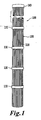
- the filter assembly 100 includes a filtering fabric (typically, a bag) made of fibers 110.
- the filtering fabric can be felt, or non-woven, fabric, as well as woven fabric, made from the fibers 110.
- the filtering fabric 120 incorporates fibers 110 made of poly(biphenyl ether sulfone)s, for example polyphenylsulfone, such as a RADEL ® R polymer.
- the filtering fabric 120 incorporates fibers 110 made of a blend of poly(biphenyl ether sulfone) and poly(imide sulfone).
- the filtering fabric 120 is free of poly(phenylene sulphide) fibers.
- the filter assembly 100 can filter particulates from a particulate laden gas as the gas passes through each filter assembly 100.
- Each filter assembly 100 can be supported at its upper end by a flange 140 coupled to a tube sheet 250 of the filtration system 200 ( Fig. 2 ) and can hang downwardly in a substantially vertical direction.
- the flange 140 can bear the weight of the filter assembly 100 when attached to the tube sheet 250.
- the flange is made from a suitable material, such as stamped, drawn or otherwise formed metal.
- the length of the filter assembly 100 can vary, for example from a few centimeters to a few meters. Also, the filter assemblies 100 can be connected in series. For example, the filter assemblies 100 can be modules of a filtration system made of several filter assemblies. The filter assembly 100 is preferably open on both ends. Alternatively, the filter assembly 100 can be closed at one or both ends. The filter assembly 100 can have any suitable configuration cross-section, such as for example circular, oval or square.
- the filtering fabric 120 is mounted on a frame 130 configured to support the filtering fabric 120 in a radial direction.
- the frame 130 can include support rings sewn into the filtering fabric 120.
- the frame 130 can include a support cage or a perforated tube on which the filtering fabric 120 is mounted.
- the support rings 130 and/or the support cage and/or the tube can be made of metal, perforated sheet metal, expanded metal or mesh screen, or other suitable materials.
- the support rings, tube and/or cage can be coupled to the flange 140.
- the filtering fabric 120 can be formed in a substantially tubular shape.
- the filtering fabric 120 includes a pleaded element with accordion folds at its inner and outer peripheries.
- the filtering fabric 120 can be attached to the flange and/or support rings/cage/tube, for example via a potting material.
- the filter assembly 100 can be incorporated, for example, in a filtration system, or baghouse, of a coal-fired power generation plant or a cement plant. In that respect, the filter assembly 100 could replace the presently commonly used filter assemblies comprising poly(phenylene sulphide) fibers.
- the fibers 110 can thus provide an alternative source of material to address the limited supply of conventional materials used in industrial filter assemblies, which need to be periodically replaced.
- the fibers 110 can also provide a filter assembly 100 that can sustain high operating temperatures and acidic environments.
- the fibers 110 can be made out of poly(biphenyl ether sulfone) or blends of poly(biphenyl ether sulfone) and poly(imide sulfone). In this case, the fibers 110 have such chemical compositions that they can provide a stronger resistance to oxidation compared to poly(phenylene sulphide). The fibers 110 also present a resistance to hydrolysis.
- the filter assembly 100 for use according to the present invention can offer a number of benefits for industrial filter assemblies.
- the RADEL ® R fibers 110 do not breakdown oxidatively, and thus improve the longevity of the filter assembly 100, which does not clog up as quickly and need not be replaced as frequently.
- the filter assembly 100 can operate at higher temperatures, thus providing improved operational efficiencies of the overall unit.
- the filter assembly 100 can be operated through more shaker cycles thereby extending the filter assembly life.
- the physical attributes of the fibers 110 provide new and improved design options allowing for even further filtration improvements.
- Coal combustion flue gas contains typically well above 5 vol. % of CO 2 , very often above 10 vol. % of CO 2 , and often 12.5 vol. % CO 2 or more. It generally also comprises more than 400, 600, 800, 1000, 1200 or even 1400 ppm of sulfur oxides (SO x ), and more than 125, 250, 375 or even 500 ppm of nitrogen oxides (NO x ), depending on the coal composition.
- SO x is a general term given to a mixture of sulfur oxides, the two major components of which are sulfur dioxide (SO 2 ) and sulfur trioxide (SO 3 ).
- NO x is a general term given to a mixture of nitrogen oxides, the two major components of which are nitric oxide (NO) and nitrogen dioxide (NO 2 ).
- the filter assembly for use according to the present invention advantageously does not breakdown oxidatively in the presence of coal combustion flue gas, and in particular in the presence of nitric acid or sulfuric acid, that are produced from the sulfur and nitrogen oxides.
- the filter assembly for use according to the present invention advantageously does not breakdown in a coal combustion flue gas stack environment, which is typically above 125°C, 150°C, 170°C, 200°C, 220°C or even higher, depending on the distance to the combustion zone, i.e. the exact location of the filter in the flue gas stack.
- the filter assembly for use according to the present invention may also comprise surface active fibers.
- the filter assembly for use according to the present invention is particularly well suited for the filtration of coal burning power generation plant flue gas.
- the filtration system for use according to the present invention comprises a plurality of filter assemblies, at least one of them being the filter assembly as above described, said filtration system further comprising a gas inlet receiving the coal combustion flue gas.
- each of the filter assemblies of the filtration system for use according to the present invention is as above described.
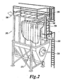
- FIG 2 is a diagram illustrating a non-limiting embodiment of a filtration system (or scrubber system, or baghouse) 200 for use according to the present invention including filter assemblies 100 with fibers 110.
- This filtration system 200 can be incorporated in a coal-fired power generation plant or in a processing plant, such as a rock and/or cement plants ad steel and/or coke mills.
- the filtration system 200 includes a gas inlet 210, in which flue gas to be filtered is inserted. The gas is then
- Each of the filter assemblies 220 can be similar to the filter assemblies 100 with filtering fabric 120 shown in Fig. 1 , but other configurations are possible.
- the filter assemblies 220 include a fabric made of fibers, such as fibers 110.
- the filter assemblies 220 can be attached to the tube sheet 250 via their flanges.
- the filter assemblies 220 can hang vertically inside the unit and can be held in place by clamps, snapbands or hold-downs.
- the filter assemblies 220 can trap various components from the flue gas, including fly ash, sulfur dioxide, SO 3 , CO 2 , mercury, nitrogen dioxide, and other pollution molecules and combustion residues.
- the filter assemblies 220 can trap these components mechanically and/or chemically, for example via a surface active fiber.
- the filtered gas then exits the filtration system 200 via gas outlet 290.
- the filter assemblies 220 can function in a high temperature environment, for example around 170°C, and in an acidic environment (e.g., in the presence of sulfuric acid or nitric acid) for an extended amount of time (e.g., three or more years). During this time, the filter assemblies 220 can be regularly cleaned, or discharged of debris, via some type of agitation system, such as a pulse jet, a shaker system, reverse air or some mixture thereof.
- the filtration system 200 can include a pulse jet system 260 configured to generate a blast of compressed air, which is injected into the top of the opening of the filter assemblies 220. The air can be supplied from a blowpipe which feeds into venturies located above the filter assembly.
- the air blast creates a shock wave that causes the bag to flex and particulate to release into a hopper 270 below. Because of the accumulation of debris over time, the agitation of the filter assemblies, and the rough environment, the filter assemblies 220 age and eventually need to be replaced. The filter assemblies can be serviced and replaced via top access hatches 280.
- a filtration system 200 can include thousands of such filter assemblies 220.
- a filtration system 200 can include 10,000 filter assemblies 220, representing thousands of pounds of fibers.
- the cost of such replacement can be great. This is another reason why increasing the longevity of the filters can be particularly beneficial in these applications, and why the filtration systems for use in the present invention can lead to significant cost efficiencies.
- Another aspect of the present invention is directed to the use of a filter assembly comprising a frame and a fabric mounted on said frame, wherein said fabric comprises fibers (F) comprising at least one polymer material (P) selected from the group consisting of a poly(biphenyl ether sulfone) and blends of poly(biphenyl ether sulfone) and poly(imide sulfone) for the filtration of coal combustion flue gas.
- F fibers
- P polymer material
- Said combustion flue gas may be a coal burning power generation plant flue gas, and may typically comprises more than 400 ppm of sulfur oxides and more than 125 ppm of nitrogen oxides.
- the polymer material (P) is the polymer material (P)
- Polymer material (P) is selected from the group consisting of a poly(biphenyl ether sulfone)) and blends of poly(biphenyl ether sulfone) and poly(imide sulfone).
- poly(biphenyl ether sulfone) is intended to denote a polycondensate of which more than 50 wt. % of the recurring units are recurring units (R1) of one or more formulae containing at least one p-biphenylene group : at least one ether group (-O-) and at least one sulfone group (-SO 2 -).
- recurring units (R1) are recurring units of one or more formulae of the general type : wherein R 1 through R 4 are -O-, -SO 2 -, -S-, -CO-, with the proviso that at least one of R 1 through R 4 is -SO 2 - and at least one of R 1 through R 4 is -O- ;
- Ar 1 , Ar 2 and Ar 3 are arylene groups containing 6 to 24 carbon atoms, and are preferably phenylene or p-biphenylene; and a and b are either 0 or 1.
- recurring units (R1) are chosen from and mixtures thereof.
- recurring units (R1) are either or or a mix of with wherein the weight amount of the recurring units (6) contained in the mix, based on the total amount of the recurring units (4) and (6) of which the mix consists, is between 10 and 99 %, and preferably between 50 and 95 %.
- recurring units (4) or a mix of recurring units (4) and (6) as recurring units (R1).
- recurring units (2) as recurring units (R1) provides in general the best overall cost-properties balance, and the highest level of toughness.
- a polyphenylsulfone is intended to denote any polycondensation polymer of which more than 50 wt. % of the recurring units are recurring units (R1) of formula (2).
- the poly(biphenyl ether sulfone) may be.notably a homopolymer, a random, alternating or block copolymer.
- its recurring units may notably be composed of (i) recurring units (R1) of at least two different formulae chosen from formulae (2), (3), (4), (5) or (6), or (ii) recurring units (R1) of one or more formulae chosen from formulae (2), (3), (4), (5) or (6) (especially, recurring units of formula (2)) and recurring units (R1*), different from recurring units (R1), such as : and
- more than 70 wt. %, more preferably more than 85 wt. % of the recurring units of the poly(biphenyl ether sulfone) are recurring units (R1). Still more preferably, essentially all the recurring units of the poly(biphenyl ether sulfone) are recurring units (R1). Most preferably, all the recurring units of the poly(biphenyl ether sulfone) are recurring units (R1).
- the poly(biphenyl ether sulfone) is a polyphenylsulfone homopolymer, i.e. a polymer of which essentially all, if not all, the recurring units are of formula (2).
- RADEL ® R polyphenylsulfone from Solvay Advanced Polymers, L.L.C. is an example of a polyphenylsulfone homopolymer.
- a poly(imide sulfone) is intended to denote imide-containing, sulfone-containing polymer comprising structural units (R2) having the general formula (I) : wherein V is a tetravalent linker without limitation, as long as the linker does not impede synthesis or use of the poly(imide sulfone) ; and R in formula (I) is a substituted or unsubstituted divalent organic radical without limitation, as long as the divalent organic radical does not impede synthesis or use of the poly(imide sulfone).
- the poly(imide sulfone) comprises generally above 5 wt. %, preferably above 50 wt. %, and more preferably above 90 wt. % of structural units (R2), based on the total weight of the poly(imide sulfone). Still more preferably, the poly(imide sulfone) is a poly(imide sulfone) homopolymer, i.e. essentially all, if not all, the structural units of the poly(imide sulfone) are structural units (R2).
- the number of structural units (R2) per polymer chain is, by definition of a polymer, above 1 ; it is typically from about 10 to about 1000 or more, and preferably from about 10 to about 500.
- Suitable linkers include but are not limited to : (a) substituted or unsubstituted, saturated, unsaturated or aromatic monocyclic or polycyclic groups having about 5 to about 50 carbon atoms, (b) substituted or unsubstituted, linear or branched, saturated or unsaturated alkyl groups having 1 to about 30 carbon atoms; or mixtures thereof.
- Preferred linkers include but are not limited to tetravalent aromatic radicals, such as wherein W is in some embodiments a divalent moiety selected from the group consisting of-O-,-S-,-C(O)-,-SO 2 -, -C y H 2y - (y being an integer from 1 to 5), and halogenated derivatives thereof, including perfluoroalkylene groups, or a group of the formula-O-D-O-wherein the divalent bonds of the-O-or the-O-D-O-group are in the 3,3', 3,4', 4,3', or the 4, 4' positions, and wherein D comprises divalent radicals of formulae : wherein Q in above formula includes but is not limited to a divalent moiety-selected from the group consisting of-O-,-S-,-C (O)-,-SO 2 -, - C y H 2y - (y being an integer from 1 to 5) such as -C(CH 3 ) 2 -
- R in formula (I) includes but is not limited to substituted or unsubstituted divalent organic radicals such as : (a) aromatic hydrocarbon radicals having about 6 to about 20 carbon atoms and halogenated derivatives thereof; (b) straight or branched chain alkylene radicals having about 2 to about 20 carbon atoms; (c) cycloalkylene radicals having about 3 to about 20 carbon atoms, or (d) divalent radicals of the general formula (II) : wherein Q includes but is not limited to a divalent moiety selected from the group consisting of-O-,-S-,-C (O)-; SO 2 -, -C y H 2y - (y being an integer from 1 to 5) such as -C(CH 3 ) 2 , and halogenated derivatives thereof, including perfluoroalkylene groups.
- divalent organic radicals such as : (a) aromatic hydrocarbon radicals having about 6 to about 20 carbon atoms and halogenated derivatives thereof;
- R is essentially free of benzylic hydrogens.
- the poly(imide sulfone) is a polyetherimide sulfone and R also contains aryl sulfone and/or aryl ether linkages such that at least 50 mole % of the repeat units of any polyetherimide sulfone contain at least one aryl ether linkage, at least one aryl sulfone linkage and at least two aryl imide linkages.
- the linking group W in tetravalent aromatic radicals comprises a group of the formula -O-D-O-as in the formula: wherein R 3 is selected from the group consisting of halogen, fluoro, chloro, bromo, C 1-32 alkyl, cycloalkyl, or alkenyl; C 1-32 alkoxy or alkenyloxy; or cyano, and "q" has a value of 0-3.
- the value of "q" is zero; and wherein “D” is a divalent aromatic group derived from a dihydroxy substituted aromatic hydrocarbon, and has the general formula (III) : where "A 1 " represents an aromatic group including, but not limited to, phenylene, biphenylene, naphthylene, etc.
- "E” may be an alkylene or alkylidene group including, but not limited to, methylene, ethylene, ethylidene, propylene, propylidene, isopropylidene, butylene, butylidene, isobutylidene, amylene, amylidene, isoamylidene, etc.
- E when “E” is an alkylene or alkylidene group, it may also consist of two or more alkylene or alkylidene groups connected by a moiety different from alkylene or alkylidene, including, but not limited to, an aromatic linkage; a tertiary nitrogen linkage; an ether linkage; a carbonyl linkage; a silicon-containing linkage, silane, siloxy; or a sulfur-containing linkage including, but not limited to, sulphide, sulfoxide, sulfone, etc.; or a phosphorus-containing linkage including, but not limited to, phosphinyl, phosphonyl, etc.
- E may be a cycloaliphatic group non- limiting examples of which include cyclopentylidene, cyclohexylidene, 3, 3,5-trimethylcyclohexylidene, methylcyclohexylidene, bicyclo [2.2. 1] hept-2-ylidene, 1,7, 7-trimethylbicyclo [2.2.
- hept-2-ylidene isopropylidene, neopentylidene, cyclopentadecylidene, cyclododecylidene, and adamantylidene
- a sulfur-containing linkage including, but not limited to, sulphide, sulfoxide or sulfone
- a phosphorus-containing linkage including, but not limited to, phosphinyl or phosphonyl
- an ether linkage a carbonyl group; a tertiary nitrogen group; or a silicon-containing linkage including, but not limited to, silane or siloxy.
- R 4 independently at each occurrence comprises a monovalent hydrocarbon group including, but not limited to, alkenyl, allyl, alkyl, aryl, aralkyl, alkaryl, or cycloalkyl.
- the dihaloalkylidene group is a dichloroalkylidene, particularly gem-dichloroalkylidene group.
- Y 1 independently at each occurrence may be an inorganic atom including, but not limited to, halogen (fluorine, bromine, chlorine); an inorganic group containing more than one inorganic atom including, but not limited to, nitro; an organic group including, but not limited to, a monovalent hydrocarbon group including, but not limited to, alkenyl, allyl, alkyl, aryl, aralkyl, alkaryl, or cycloalkyl, or an oxy group including, but not limited to, OR 5 wherein R 5 is a monovalent hydrocarbon group including, but not limited to, alkyl, aryl, aralkyl, alkaryl, or cycloalkyl; it being only necessary that Y 1 be inert to and unaffected by the reactants and reaction conditions used to prepare the polymer.
- Y 1 comprises a halo group or C1-C6 alkyl group.
- the letter “m” represents any integer from and including zero through the number of replaceable hydrogens on A available for substitution; “p” represents an integer from and including zero through the number of replaceable hydrogens on E available for substitution; “t” represents an integer equal to at least one; “s” represents an integer equal to either zero or one; and “u” represents any integer including zero.
- "u” is an integer with a value of from 0 to about 5.
- dihydroxy-substituted aromatic hydrocarbons "D" when more than one Y 1 substituent is present, they may be the same or different. The same holds true for the R'substituent.
- both A 1 radicals are unsubstituted phenylene radicals; and E is an alkylidene group such as isopropylidene.
- both A1 radicals are p-phenylene, although both may be o-or m-phenylene or one o-or m-phenylene and the other p- phenylene.
- "E” may be an unsaturated alkylidene group.
- Suitable dihydroxy-substituted aromatic hydrocarbons of this type include those of the formula (IV) : where each R is independently hydrogen, chlorine, bromine, or a C 1-30 monovalent hydrocarbon or hydrocarbonoxy group, each Z is hydrogen, chlorine or bromine, subject to the provision that at least one Z is chlorine or bromine.
- Suitable dihydroxy-substituted aromatic hydrocarbons also include those of the formula (V): where each R 7 is independently hydrogen, chlorine, bromine, or a C 1-30 monovalent hydrocarbon or hydrocarbonoxy group, and R 8 and R 9 are independently hydrogen or a C 1-30 hydrocarbon group.
- dihydroxy-substituted aromatic hydrocarbons that may be used include, but are not limited to, bis (4-hydroxyphenyl) sulphide, bis (4-hydroxyphenyl) ether, bis (4- hydroxyphenyl) sulfone, bis (4-hydroxyphenyl) sulfoxide, 1,4-dihydroxybenzene, 4,4'-oxydiphenol, 2,2-bis (4-hydroxyphenyl) hexafluoropropane, 4,4'- (3, 3,5-trimethylcyclohexylidene) diphenol; 4,4'-bis (3,5-dimethyl) diphenol, 1,1-bis (4-hydroxy-3-methylphenyl) cyclohexane; 4,4-bis (4-hydroxyphenyl) heptane; 2, 4'-dihydroxydiphenylmethane; bis (2-hydroxyphenyl) methane; bis (4- hydroxyphenyl) methane; bis (4-hydroxy-5-nitrophenyl) methan
- dihydroxy-substituted aromatic hydrocarbons when the moiety "E" is an alkylene or alkylidene group, it may be part of one or more fused rings attached to one or more aromatic groups bearing one hydroxy substituent.
- Suitable dihydroxy-substituted aromatic-hydrocarbons of this type include those containing indane structural units such as 3- (4-hydroxyphenyl)-1, 1, 3-trimethylindan-5-ol and 1- (4-hydroxyphenyl)-1, 3, 3-trimethylindan-5-ol.
- suitable dihydroxy-substituted aromatic hydrocarbons of the type comprising one or more alkylene or alkylidene groups as part of fused rings are the 2,2,2', 2'-tetrahydro-1, 1'-spirobi [1H-indene] diols, illustrative examples of which include 2,2, 2', 2'-tetrahydro-3,3, 3', 3'-tetramethyl-1, 1'-spirobi [1H-indene]-6, 6'-diol (sometimes known as "SBI").
- Mixtures comprising any of the foregoing dihydroxy- substituted aromatic hydrocarbons may also be employed.
- Preferred poly(imide sulfone) resins are polyetherimide sulfone resins comprising more than 1, typically about 10 to about 1000 or more, and more preferably about 10 to about 500 structural units, of the formula (VI) wherein the moiety R is as previously defined for formula (I) ; T is-O-or a group of the formula-O-D-O-wherein the divalent bonds of the-O-or the-O-D-O-group are in the 3,3', 3,4', 4, 3', or the 4, 4' positions, and wherein D includes, but is not limited, to divalent radicals as defined above.
- a polyetherimide sulfone may be a copolymer, which, in addition to the etherimide units described above, further contains polyimide structural units of the formula (VII) wherein R is as previously defined for formula (I) and M includes, but is not limited to, radicals of formula (VIII) chosen from and
- Thermoplastic poly(imide sulfone)s can be derived from reactants comprising one or more aromatic diamines or their chemically equivalent derivatives and one or more aromatic tetracarboxylic acid cyclic dianhydrides (sometimes referred to hereinafter as aromatic dianhydrides), aromatic tetracarboxylic acids, or their derivatives capable of forming cyclic anhydrides.
- aromatic dianhydrides aromatic tetracarboxylic acid cyclic dianhydrides
- aromatic tetracarboxylic acids or their derivatives capable of forming cyclic anhydrides.
- at least a portion of one or the other of or at least a portion of each of the reactants comprising aromatic diamines and aromatic dianhydrides comprises a sulfone linkage.
- all of one or the other of or each of the reactants comprising aromatic diamines and aromatic dianhydrides comprises a sulfone linkage.
- the reactants react to form polymers comprising cyclic im
- aromatic dianhydrides comprise : 4,4'-bis (3,4-dicarboxyphenoxy) diphenyl sulfone dianhydride; 4,4'-bis (2,3- dicarboxyphenoxy) diphenyl sulfone dianhydride; 4- (2,3-dicarboxyphenoxy)-4'- (3, 4-dicarboxyphenoxy) diphenyl sulfone dianhydride and mixtures thereof.
- aromatic dianhydrides comprise : 2,2-bis-(4-(3,4-dicarboxyphenoxy) phenyl) propane dianhydride; 4,4'-bis (3,4- dicarboxyphenoxy) diphenyl ether dianhydride; 4,4'-bis (3,4- dicarboxyphenoxy) diphenyl sulphide dianhydride; 4,4'-bis (3,4- dicarboxyphenoxy) benzophenone dianhydride; 2,2-bis ([4- (2, 3- dicarboxyphenoxy) phenyl] propane dianhydride; 4,4'-bis (2,3-dicarboxyphenoxy) diphenyl ether dianhydride; 4,4'-bis (2,3- dicarboxyphenoxy) diphenyl sulphide dianhydride; 4,4'-bis (2,3- dicarboxyphenoxy) benzophenone dianhydride; 2- [4- (3, 4-dicarboxyphenoxy) phenyl]-2- [4- (2, 4-
- the aromatic dianhydride employed in the synthesis of the poly(imide sulfone) composition comprises an aromatic bis (ether anhydride) composition comprising at least about 90 mole % 2,2-bis [4- (3, 4-dicarboxyphenoxy) phenyl] propane dianhydride, or at least about 95 mole % 2,2-bis [4- (3, 4-dicarboxyphenoxy) phenyl] propane dianhydride based on total moles dianhydride present.
- this particular aromatic bis (ether anhydride) composition is referred to as bisphenol A dianhydride or "BPADA".
- preferred aromatic dianhydrides are bisphenol A dianhydride, pyromellitic dianhydride, biphenyltetracarboxylic acid dianhydride, oxydiphthalic anhydride and mixtures thereof.
- suitable aromatic diamines comprise a divalent organic radical selected from aromatic hydrocarbon radicals having 6 to about 24 carbon atoms and substituted derivatives thereof.
- said aromatic hydrocarbon radicals may be monocyclic, polycyclic or fused.
- suitable aromatic diamines comprise divalent aromatic hydrocarbon radicals of the general formula (IX) wherein the unassigned positional isomer about the aromatic ring is either meta or para to Q, and Q is a covalent bond or a member selected from the group consisting of formulas (X): and an alkylene or alkylidene group of the formula C y H 2y , wherein y is an integer from 1 to 5 inclusive. In some particular embodiments y has the value of one or two.
- Illustrative linking groups include, but are not limited to, methylene, ethylene, ethylidene, vinylidene, halogen-substituted vinylidene, and isopropylidene.
- the unassigned positional isomer about the aromatic ring in formula (IX) is para to Q.
- the two amino groups in aromatic diamines are separated by at least two and sometimes by at least three ring carbon atoms.
- the amino group or groups are located in different aromatic rings of a polycyclic aromatic moiety, they are often separated from the direct linkage or from the linking moiety between any two aromatic rings by at least two and sometimes by at least three ring carbon atoms.
- aromatic diamines comprise aromatic hydrocarbon radicals including, but not limited to, phenyl, biphenyl, naphthyl, bis (phenyl) -2, 2-propane, and their substituted derivatives.
- substituents include one or more halogen groups, such as fluoro, chloro, or bromo, or mixtures thereof; or one or more straight-chain-, branched-, or cycloalkyl-groups having from 1 to 22 carbon atoms, such as methyl, tert-butyl, or mixtures thereof.
- substituents for aromatic hydrocarbon radicals when present, are selected from the group consisting of halogens, chloro, ethers, sulfones, perfluoroalkyl, methyl, t-butyl and mixtures thereof. In other particular embodiments said aromatic hydrocarbon radicals are unsubstituted.
- suitable aromatic diamines comprise meta-phenylenediamine; para-phenylenediamine; mixtures of meta-and para-phenylenediamine; isomeric 2-methyl-and 5-methyl-4, 6-diethyl-1, 3-phenylenediamines or their mixtures; bis (4-aminophenyl)-2, 2-propane; bis (2-chloro-4-amino-3,5-diethylphenyl) methane, 4,4'-diaminodiphenyl, 3,4'-diaminodiphenyl, 4, 4'-diaminodiphenyl ether (sometimes referred to as 4, 4'-oxydianiline); 3, 4'-diaminodiphenyl ether, 3,3'-diaminodiphenyl ether, 4, 4'-diaminodiphenyl sulfone, 3,4'-diaminodiphenyl sulfone, 3,3'-diaminominodip
- the preferred aromatic diamines are free of benzylic hydrogens and also contain aryl sulfone linkages.
- Diaminodiphenyl sulfone (DDS), bis(aminophenoxy phenyl) sulfones-(BAPS) and mixtures thereof are particularly preferred aromatic diamines.
- the sulfone groups contained in the poly(imide sulfone) are generally contained in tetravalent linker V and/or in the divalent radical R.
- a first suitable tetravalent linker V including a sulfone group is wherein W is -SO 2 -.
- Another suitable tetravalent linker V including a sulfone group is wherein W is an -O-D-O-group, wherein D is wherein Q is -SO 2 -.
- Still another suitable tetravalent linker V including a sulfone group is wherein R 3 is selected from the group consisting of halogen, fluoro, chloro, bromo, C-32 alkyl, cycloalkyl, or alkenyl; Cl-32 alkoxy or alkenyloxy; or cyano, and "q" has a value of 0-3 ; wherein "D” is a divalent aromatic group derived from a dihydroxy substituted aromatic hydrocarbon, and has the general formula : where
- a suitable divalent radical R including a sulfone group is wherein Q is -SO 2 -.
- the divalent radical R contains a sulfone group, and more preferably the divalent radical R is wherein Q is -SO 2 -.
- the tetravalent linker V is preferably free of sulfone group.
- Poly(imide sulfones) especially suitable as the polymer material (P) are commercially available notably from SOLVAY ADVANCED POLYMERS, L.L.C. as EXTEM ® .
- the polymer material (P) is a blend composed of a poly(biphenyl ether sulfone) and at least one poly(imide sulfone), hereinafter referred to as blend (B).
- blend (B) the poly(biphenyl ether sulfone) contained in the blend (B) meets advantageously all the characteristics of the poly(biphenyl ether sulfone)s as above described, at any level of preference; in particular, it is preferably, a polyphenylsulfone ; the poly(imide sulfone) contained in the blend (B) meets advantageously all the characteristics of the poly(imide sulfone) as above described, at any level of preference ;the weight of the poly(biphenyl ether sulfone), based on the total weight of the blend (B) [i.e.
- the weight of the poly(biphenyl ether sulfone) plus the weight of the poly(imide sulfone)] is advantageously of at least 15 %, preferably at least 25 % , more preferably at least 35 %, still more preferably at least 40 %, and most preferably at least 45 % ; besides, the weight of the poly(biphenyl ether sulfone), based on the total weight of the blend (B) is advantageously of at most 90 %, preferably at most 80 %, and still more preferably at most 70 % ; in certain embodiments, it is of at most 55 % ; in certain other embodiments, it is above 55 %, and possibly of at least 60%.
- the polymer material (P) may also be a copolymer comprising both recurring units of the poly(biphenyl ether sulfone) and poly(imide sulfone) as above described. It may be a block or a random copolymer. In such a case, the copolymer comprises more than 50 wt. % of recurring units corresponding to the poly(biphenyl ether sulfone) recurring units as above described.
- PESU polyethersulfone
- PPSU polyphenylsulfone
- PPS poly(phenylene sulphide)
- Fiber spinning trial was conducted on a machine including a standard 1.5" single screw extruder with L/D of 24:1 and a compression ration of 3:1, two melt pumps and four drawing rollers.
- the screw had feeding, transition and metering zones of 7.5/13.5/15 inch lengths without a mixer.
- Each melt pump fed the material into a spinneret having two clusters each of 20 holes of 0.8 mm in diameter for a total of 80 strands.
- the total material residence time was about 10 minutes at 5 lbs/hr output rate.
- the strands were pulled by the four rollers, whose speeds and temperature were controlled independently.
- the first roller drew the strands at the molten state of the polymer ("hot” draw).
- the strand drawing from rest of the rollers took place at a solid state of the polymer ("cold" draw).
- Four screen packs of 325x60x20x20x20 mesh combination were used before the spinneret.
- Thermal stability property was measured through % tenacity retention of a fiber sample after exposed in a hot air oven of 170°C with no tension applied to the fiber for a prolong period.
- Fiber chemical resistance was evaluated by immersing the fiber in a testing reagent for 24 hours and then determining tensile properties and in particular tenacity retention of the chemical treated fiber. Details of the test procedure are given in the following:
- Fibers were winded on a 1" diameter glass tube (2/3 way down into the bottom) and rinsed for 1 minute to remove the finish and then dried the fiber with paper towel.
- Six tubes each loaded with different fiber samples were immersed into a glass 1000 ml wide-mouth jar filled with a chemical reagent. The jar was capped and left inside a hood at room temperature for 24 hours. The tubes were taken out from the jar, and rinsed with deionized water to rinse the remaining chemical reagent from the fiber for initial cleaning. The tubes were then dipped into a water bath as a second step clean up. The fibers were then conditioned for a day before running tensile tests.
- the PPS fibers dissolve into a concentrated nitric acid solution of 50 wt. % at room temperature and have reduced tenacity retention when treated in a less concentrated nitric acid solution at an elevated temperature.
- the PESU and PPSU fibers show superior resistance to strong base and acid solutions at room temperature, and to intermediate concentrated base and acid solutions at an elevated temperature.
- PPSU fibers still feature improved chemical resistance compared to that of PESU fibers.
- Table 2 Tenacity retention upon chemical treatment PESU PPSU PPS Denier, g/9000m 345 550 400 DPF, g/9000m 2.7 6.9 4.0 Test temperature: 23°C Sulfuric acid, 50% 96 100 87 Nitric acid, 50% 80 108 dissolved Test temperature: 80°C Sulfuric acid, 20% 96 100 89 Nitric acid, 20% 95 99 66 KOH, 37% 90 90 84
Landscapes
- Engineering & Computer Science (AREA)
- Chemical & Material Sciences (AREA)
- Textile Engineering (AREA)
- Chemical Kinetics & Catalysis (AREA)
- General Chemical & Material Sciences (AREA)
- Mechanical Engineering (AREA)
- Nanotechnology (AREA)
- Crystallography & Structural Chemistry (AREA)
- General Physics & Mathematics (AREA)
- Materials Engineering (AREA)
- Condensed Matter Physics & Semiconductors (AREA)
- Composite Materials (AREA)
- Physics & Mathematics (AREA)
- General Engineering & Computer Science (AREA)
- Filtering Materials (AREA)
- Compositions Of Macromolecular Compounds (AREA)
- Artificial Filaments (AREA)
- Woven Fabrics (AREA)
- Nonwoven Fabrics (AREA)
- Filtering Of Dispersed Particles In Gases (AREA)
Applications Claiming Priority (2)
| Application Number | Priority Date | Filing Date | Title |
|---|---|---|---|
| US89656707P | 2007-03-23 | 2007-03-23 | |
| PCT/EP2008/002287 WO2008116606A2 (en) | 2007-03-23 | 2008-03-20 | Coal combustion flue gas filters |
Publications (2)
| Publication Number | Publication Date |
|---|---|
| EP2129820A2 EP2129820A2 (en) | 2009-12-09 |
| EP2129820B1 true EP2129820B1 (en) | 2011-05-25 |
Family
ID=39531277
Family Applications (1)
| Application Number | Title | Priority Date | Filing Date |
|---|---|---|---|
| EP08734715A Not-in-force EP2129820B1 (en) | 2007-03-23 | 2008-03-20 | Use of coal combustion flue gas filters |
Country Status (9)
| Country | Link |
|---|---|
| US (1) | US20100095876A1 (enExample) |
| EP (1) | EP2129820B1 (enExample) |
| JP (1) | JP5309040B2 (enExample) |
| CN (3) | CN103361758A (enExample) |
| AT (1) | ATE510945T1 (enExample) |
| DE (1) | DE202008003982U1 (enExample) |
| ES (1) | ES2359769T3 (enExample) |
| IN (1) | IN2009CH05618A (enExample) |
| WO (2) | WO2008116837A2 (enExample) |
Families Citing this family (17)
| Publication number | Priority date | Publication date | Assignee | Title |
|---|---|---|---|---|
| DE102005026156A1 (de) * | 2005-06-06 | 2006-12-28 | Carl Freudenberg Kg | Filterschlauch |
| WO2008116837A2 (en) * | 2007-03-23 | 2008-10-02 | Solvay Advanced Polymers, L.L.C. | Polymer fibers, assemblies incorporating such polymer fibers, and systems incorporating such filter assemblies |
| US7998577B2 (en) * | 2007-12-13 | 2011-08-16 | E. I. Du Pont De Nemours And Company | Multicomponent fiber with polyarylene sulfide component |
| EP2266680A1 (en) * | 2009-06-05 | 2010-12-29 | ETH Zürich, ETH Transfer | Amine containing fibrous structure for adsorption of CO2 from atmospheric air |
| US8016124B2 (en) * | 2009-04-22 | 2011-09-13 | Honeywell International Inc. | Thin film gas separation membranes |
| JP5534035B2 (ja) * | 2010-12-27 | 2014-06-25 | 株式会社オートネットワーク技術研究所 | 自動車用絶縁電線及び自動車用ワイヤーハーネス |
| CN102108120B (zh) * | 2011-01-19 | 2013-03-13 | 吉林大学 | 含丙烯基可交联聚芳醚砜聚合物及其制备方法 |
| CN102996257A (zh) * | 2011-09-13 | 2013-03-27 | 金涌 | 一种粉煤直燃的整体联合循环发电系统 |
| CN105636677B (zh) * | 2013-10-15 | 2019-03-12 | 巴斯夫欧洲公司 | 改进过滤膜的化学稳定性 |
| CN104846473B (zh) * | 2014-02-14 | 2016-05-25 | 上海特安纶纤维有限公司 | 一种基于芳香族聚酰胺和聚芳砜的共混纤维、纱线、织物、制品及其制备方法 |
| EP3237656B1 (en) * | 2014-12-22 | 2020-05-13 | Solvay Specialty Polymers USA, LLC. | Polyphenylene fibers and corresponding fabrication methods |
| CN104667630B (zh) * | 2015-01-14 | 2017-04-19 | 上海特安纶纤维有限公司 | 一种含砜基的共混型芳族聚酰胺纤维耐高温滤料及其制造方法 |
| JP2016198722A (ja) * | 2015-04-10 | 2016-12-01 | 旭工業繊維株式会社 | エアフィルタ |
| JP7511558B2 (ja) * | 2018-12-20 | 2024-07-05 | ソルベイ スペシャルティ ポリマーズ ユーエスエー, エルエルシー | 高圧濾過のための多孔質膜 |
| EP3897933A1 (en) | 2018-12-20 | 2021-10-27 | Solvay Specialty Polymers USA, LLC. | Porous membranes for high pressure filtration |
| CN111495037B (zh) * | 2020-04-29 | 2022-03-25 | 广东凯迪服饰有限公司 | 一种聚醚砜纤维无纺布复合滤料及其制备方法 |
| CN113058339A (zh) * | 2021-04-06 | 2021-07-02 | 安徽中电环保材料股份有限公司 | 一种水泥罐装用涤纶覆膜除尘滤袋及其生产工艺 |
Family Cites Families (31)
| Publication number | Priority date | Publication date | Assignee | Title |
|---|---|---|---|---|
| US3354129A (en) | 1963-11-27 | 1967-11-21 | Phillips Petroleum Co | Production of polymers from aromatic compounds |
| JPS5645736A (en) * | 1979-09-20 | 1981-04-25 | Babcock Hitachi Kk | Dry type desulfurization process |
| US4359501A (en) * | 1981-10-28 | 1982-11-16 | Albany International Corp. | Hydrolysis resistant polyaryletherketone fabric |
| US5645925A (en) * | 1988-03-14 | 1997-07-08 | Boeing Company | Advanced composite blends |
| US4574144A (en) * | 1984-12-17 | 1986-03-04 | General Electric Company | Sulfonated polyimides and polyamic acids and method for their preparation |
| US5205968A (en) * | 1988-03-31 | 1993-04-27 | The Dow Chemical Company | Process for making a microporous membrane from a blend containing a poly(etheretherketone)-type polymer, an amorphous polymer, and a solvent |
| CA1323488C (en) * | 1988-07-13 | 1993-10-26 | Edwina Ying | Non-shrinkable hybrid yarn |
| JP2709726B2 (ja) * | 1988-09-30 | 1998-02-04 | エービービー株式会社 | バグフィルターにおける破損▲ろ▼布の検知方法 |
| DE69033282T2 (de) | 1989-05-23 | 1999-12-30 | Teijin Ltd., Osaka | Poly(arylen-äther-keton), verfahren zur herstellung desselben und dessen verwendung |
| US5149581A (en) * | 1989-11-21 | 1992-09-22 | Idemitsu Kosan Co., Ltd. | Polyether copolymers, resin compositions containing them, and molded articles formed from them |
| US5204400A (en) * | 1990-06-22 | 1993-04-20 | Amoco Corporation | Poly(biphenyl ether sulfone)compositions |
| EP0471093A1 (en) * | 1990-07-23 | 1992-02-19 | The Boeing Company | Amideimide oligomers, blends and sizings for carbon fiber composites |
| US5762798A (en) * | 1991-04-12 | 1998-06-09 | Minntech Corporation | Hollow fiber membranes and method of manufacture |
| JPH0681270A (ja) * | 1991-12-26 | 1994-03-22 | Toray Ind Inc | 繊維複合体およびその製法 |
| JPH0753209B2 (ja) * | 1992-06-01 | 1995-06-07 | 旭ファイバーグラス株式会社 | バグフィルター用クロス |
| US5628021A (en) * | 1992-12-31 | 1997-05-06 | Seiko Epson Corporation | System and method for assigning tags to control instruction processing in a superscalar processor |
| US5582632A (en) * | 1994-05-11 | 1996-12-10 | Kimberly-Clark Corporation | Corona-assisted electrostatic filtration apparatus and method |
| JPH1085571A (ja) * | 1996-07-26 | 1998-04-07 | Dainippon Ink & Chem Inc | 分離膜 |
| US5716689A (en) * | 1996-09-19 | 1998-02-10 | Integrated Process Technologies | Hollow fiber membrane carpet manufacturing method and an elementary carpet member and carpet |
| JP3299207B2 (ja) * | 1998-11-16 | 2002-07-08 | ツカサ工業株式会社 | バッグフィルタ装置 |
| US6716274B2 (en) * | 2000-09-05 | 2004-04-06 | Donaldson Company, Inc. | Air filter assembly for filtering an air stream to remove particulate matter entrained in the stream |
| JP2002180028A (ja) * | 2000-12-13 | 2002-06-26 | Kansai Research Institute | ダイオキシン類抑制剤及び該抑制剤を含む樹脂組成物 |
| JP2002317617A (ja) * | 2001-04-23 | 2002-10-31 | Yoshinobu Shoji | 排気ガスの浄化方法と、排出口周辺における浄化のため構造 |
| DE60329922D1 (de) * | 2002-09-17 | 2009-12-17 | Du Pont | Extrem flüssigkeitsundurchlässiges gewebe |
| US20040074391A1 (en) * | 2002-10-16 | 2004-04-22 | Vincent Durante | Filter system |
| US7041773B2 (en) * | 2003-09-26 | 2006-05-09 | General Electric Company | Polyimide sulfones, method and articles made therefrom |
| US7081152B2 (en) * | 2004-02-18 | 2006-07-25 | Electric Power Research Institute Incorporated | ESP performance optimization control |
| JP4687495B2 (ja) * | 2005-02-18 | 2011-05-25 | 東レ株式会社 | バグフィルター濾布およびバグフィルター |
| US7641055B2 (en) * | 2005-11-10 | 2010-01-05 | Donaldson Company, Inc. | Polysulfone and poly(N-vinyl lactam) polymer alloy and fiber and filter materials made of the alloy |
| US20080027519A1 (en) * | 2006-07-28 | 2008-01-31 | Guerrero John M | Method of treatment of ocular compartment syndromes |
| WO2008116837A2 (en) * | 2007-03-23 | 2008-10-02 | Solvay Advanced Polymers, L.L.C. | Polymer fibers, assemblies incorporating such polymer fibers, and systems incorporating such filter assemblies |
-
2008
- 2008-03-20 WO PCT/EP2008/053401 patent/WO2008116837A2/en not_active Ceased
- 2008-03-20 JP JP2009553978A patent/JP5309040B2/ja not_active Expired - Fee Related
- 2008-03-20 ES ES08718136T patent/ES2359769T3/es active Active
- 2008-03-20 CN CN2013101295049A patent/CN103361758A/zh active Pending
- 2008-03-20 DE DE202008003982U patent/DE202008003982U1/de not_active Expired - Lifetime
- 2008-03-20 US US12/531,620 patent/US20100095876A1/en not_active Abandoned
- 2008-03-20 CN CNA200880000017XA patent/CN101605932A/zh active Pending
- 2008-03-20 AT AT08734715T patent/ATE510945T1/de not_active IP Right Cessation
- 2008-03-20 EP EP08734715A patent/EP2129820B1/en not_active Not-in-force
- 2008-03-20 CN CN200880016573.6A patent/CN101680126B/zh not_active Expired - Fee Related
- 2008-03-20 WO PCT/EP2008/002287 patent/WO2008116606A2/en not_active Ceased
-
2009
- 2009-09-23 IN IN5618CH2009 patent/IN2009CH05618A/en unknown
Also Published As
| Publication number | Publication date |
|---|---|
| IN2009CH05618A (enExample) | 2009-12-11 |
| WO2008116837A3 (en) | 2008-12-31 |
| DE202008003982U1 (de) | 2008-06-19 |
| US20100095876A1 (en) | 2010-04-22 |
| CN101605932A (zh) | 2009-12-16 |
| CN101680126B (zh) | 2013-09-18 |
| CN101680126A (zh) | 2010-03-24 |
| ATE510945T1 (de) | 2011-06-15 |
| EP2129820A2 (en) | 2009-12-09 |
| WO2008116606A2 (en) | 2008-10-02 |
| WO2008116606A3 (en) | 2009-01-22 |
| JP5309040B2 (ja) | 2013-10-09 |
| CN103361758A (zh) | 2013-10-23 |
| WO2008116837A2 (en) | 2008-10-02 |
| JP2010522067A (ja) | 2010-07-01 |
| ES2359769T3 (es) | 2011-05-26 |
Similar Documents
| Publication | Publication Date | Title |
|---|---|---|
| EP2129820B1 (en) | Use of coal combustion flue gas filters | |
| EP2278051B1 (en) | Improved fabrics | |
| EP1326699B1 (en) | Filter structure and method for filtering air for a gas turbine system | |
| EP1358272B2 (en) | Filter structure comprising polymer nanofibers | |
| EP1326698B2 (en) | Air filter assembly for filtering an air stream to remove particulate matter entrained in the stream | |
| US20160175748A1 (en) | Multi-layered nanofiber filter having improved heat resistance, and method for manufacturing same | |
| JP7264316B2 (ja) | 活性炭素繊維、活性炭素繊維成形体、及びそれらの製造方法、有機溶剤吸脱着処理装置、有機溶剤回収システム、有機溶剤吸脱着処理方法、並びに有機溶剤回収方法 | |
| KR102524943B1 (ko) | 불융화 폴리페닐렌에테르 섬유, 불융화 폴리페닐렌에테르 성형체, 탄소 섬유, 활성 탄소 섬유, 탄소 섬유 성형체, 활성 탄소 섬유 성형체, 및 그의 제조 방법 | |
| EP1925352B1 (en) | Polymer, polymer microfiber, polymer nanofiber and applications including filter structure | |
| WO2023054495A1 (ja) | 耐炎化ポリフェニレンエーテル成形体、耐炎化ポリフェニレンエーテル繊維成形体、炭素成形体、活性炭素成形体、及びこれらの製造方法 | |
| AU2007201000A1 (en) | Polymer fine fiber and fine fiber layer |
Legal Events
| Date | Code | Title | Description |
|---|---|---|---|
| PUAI | Public reference made under article 153(3) epc to a published international application that has entered the european phase |
Free format text: ORIGINAL CODE: 0009012 |
|
| 17P | Request for examination filed |
Effective date: 20091023 |
|
| AK | Designated contracting states |
Kind code of ref document: A2 Designated state(s): AT BE BG CH CY CZ DE DK EE ES FI FR GB GR HR HU IE IS IT LI LT LU LV MC MT NL NO PL PT RO SE SI SK TR |
|
| 17Q | First examination report despatched |
Effective date: 20100205 |
|
| RTI1 | Title (correction) |
Free format text: USE OF COAL COMBUSTION FLUE GAS FILTERS |
|
| GRAP | Despatch of communication of intention to grant a patent |
Free format text: ORIGINAL CODE: EPIDOSNIGR1 |
|
| DAX | Request for extension of the european patent (deleted) | ||
| GRAS | Grant fee paid |
Free format text: ORIGINAL CODE: EPIDOSNIGR3 |
|
| GRAA | (expected) grant |
Free format text: ORIGINAL CODE: 0009210 |
|
| AK | Designated contracting states |
Kind code of ref document: B1 Designated state(s): AT BE BG CH CY CZ DE DK EE ES FI FR GB GR HR HU IE IS IT LI LT LU LV MC MT NL NO PL PT RO SE SI SK TR |
|
| REG | Reference to a national code |
Ref country code: GB Ref legal event code: FG4D |
|
| REG | Reference to a national code |
Ref country code: CH Ref legal event code: EP |
|
| REG | Reference to a national code |
Ref country code: IE Ref legal event code: FG4D |
|
| REG | Reference to a national code |
Ref country code: DE Ref legal event code: R096 Ref document number: 602008007190 Country of ref document: DE Effective date: 20110707 |
|
| REG | Reference to a national code |
Ref country code: NL Ref legal event code: VDEP Effective date: 20110525 |
|
| PG25 | Lapsed in a contracting state [announced via postgrant information from national office to epo] |
Ref country code: HR Free format text: LAPSE BECAUSE OF FAILURE TO SUBMIT A TRANSLATION OF THE DESCRIPTION OR TO PAY THE FEE WITHIN THE PRESCRIBED TIME-LIMIT Effective date: 20110525 Ref country code: PT Free format text: LAPSE BECAUSE OF FAILURE TO SUBMIT A TRANSLATION OF THE DESCRIPTION OR TO PAY THE FEE WITHIN THE PRESCRIBED TIME-LIMIT Effective date: 20110926 Ref country code: LT Free format text: LAPSE BECAUSE OF FAILURE TO SUBMIT A TRANSLATION OF THE DESCRIPTION OR TO PAY THE FEE WITHIN THE PRESCRIBED TIME-LIMIT Effective date: 20110525 Ref country code: SE Free format text: LAPSE BECAUSE OF FAILURE TO SUBMIT A TRANSLATION OF THE DESCRIPTION OR TO PAY THE FEE WITHIN THE PRESCRIBED TIME-LIMIT Effective date: 20110525 Ref country code: NO Free format text: LAPSE BECAUSE OF FAILURE TO SUBMIT A TRANSLATION OF THE DESCRIPTION OR TO PAY THE FEE WITHIN THE PRESCRIBED TIME-LIMIT Effective date: 20110825 |
|
| PG25 | Lapsed in a contracting state [announced via postgrant information from national office to epo] |
Ref country code: FI Free format text: LAPSE BECAUSE OF FAILURE TO SUBMIT A TRANSLATION OF THE DESCRIPTION OR TO PAY THE FEE WITHIN THE PRESCRIBED TIME-LIMIT Effective date: 20110525 Ref country code: LV Free format text: LAPSE BECAUSE OF FAILURE TO SUBMIT A TRANSLATION OF THE DESCRIPTION OR TO PAY THE FEE WITHIN THE PRESCRIBED TIME-LIMIT Effective date: 20110525 Ref country code: ES Free format text: LAPSE BECAUSE OF FAILURE TO SUBMIT A TRANSLATION OF THE DESCRIPTION OR TO PAY THE FEE WITHIN THE PRESCRIBED TIME-LIMIT Effective date: 20110905 Ref country code: GR Free format text: LAPSE BECAUSE OF FAILURE TO SUBMIT A TRANSLATION OF THE DESCRIPTION OR TO PAY THE FEE WITHIN THE PRESCRIBED TIME-LIMIT Effective date: 20110826 Ref country code: AT Free format text: LAPSE BECAUSE OF FAILURE TO SUBMIT A TRANSLATION OF THE DESCRIPTION OR TO PAY THE FEE WITHIN THE PRESCRIBED TIME-LIMIT Effective date: 20110525 Ref country code: BE Free format text: LAPSE BECAUSE OF FAILURE TO SUBMIT A TRANSLATION OF THE DESCRIPTION OR TO PAY THE FEE WITHIN THE PRESCRIBED TIME-LIMIT Effective date: 20110525 Ref country code: SI Free format text: LAPSE BECAUSE OF FAILURE TO SUBMIT A TRANSLATION OF THE DESCRIPTION OR TO PAY THE FEE WITHIN THE PRESCRIBED TIME-LIMIT Effective date: 20110525 Ref country code: CY Free format text: LAPSE BECAUSE OF FAILURE TO SUBMIT A TRANSLATION OF THE DESCRIPTION OR TO PAY THE FEE WITHIN THE PRESCRIBED TIME-LIMIT Effective date: 20110525 Ref country code: IS Free format text: LAPSE BECAUSE OF FAILURE TO SUBMIT A TRANSLATION OF THE DESCRIPTION OR TO PAY THE FEE WITHIN THE PRESCRIBED TIME-LIMIT Effective date: 20110925 |
|
| PG25 | Lapsed in a contracting state [announced via postgrant information from national office to epo] |
Ref country code: NL Free format text: LAPSE BECAUSE OF FAILURE TO SUBMIT A TRANSLATION OF THE DESCRIPTION OR TO PAY THE FEE WITHIN THE PRESCRIBED TIME-LIMIT Effective date: 20110525 |
|
| PG25 | Lapsed in a contracting state [announced via postgrant information from national office to epo] |
Ref country code: EE Free format text: LAPSE BECAUSE OF FAILURE TO SUBMIT A TRANSLATION OF THE DESCRIPTION OR TO PAY THE FEE WITHIN THE PRESCRIBED TIME-LIMIT Effective date: 20110525 Ref country code: CZ Free format text: LAPSE BECAUSE OF FAILURE TO SUBMIT A TRANSLATION OF THE DESCRIPTION OR TO PAY THE FEE WITHIN THE PRESCRIBED TIME-LIMIT Effective date: 20110525 |
|
| PG25 | Lapsed in a contracting state [announced via postgrant information from national office to epo] |
Ref country code: PL Free format text: LAPSE BECAUSE OF FAILURE TO SUBMIT A TRANSLATION OF THE DESCRIPTION OR TO PAY THE FEE WITHIN THE PRESCRIBED TIME-LIMIT Effective date: 20110525 Ref country code: RO Free format text: LAPSE BECAUSE OF FAILURE TO SUBMIT A TRANSLATION OF THE DESCRIPTION OR TO PAY THE FEE WITHIN THE PRESCRIBED TIME-LIMIT Effective date: 20110525 Ref country code: SK Free format text: LAPSE BECAUSE OF FAILURE TO SUBMIT A TRANSLATION OF THE DESCRIPTION OR TO PAY THE FEE WITHIN THE PRESCRIBED TIME-LIMIT Effective date: 20110525 Ref country code: DK Free format text: LAPSE BECAUSE OF FAILURE TO SUBMIT A TRANSLATION OF THE DESCRIPTION OR TO PAY THE FEE WITHIN THE PRESCRIBED TIME-LIMIT Effective date: 20110525 |
|
| PLBE | No opposition filed within time limit |
Free format text: ORIGINAL CODE: 0009261 |
|
| STAA | Information on the status of an ep patent application or granted ep patent |
Free format text: STATUS: NO OPPOSITION FILED WITHIN TIME LIMIT |
|
| 26N | No opposition filed |
Effective date: 20120228 |
|
| PG25 | Lapsed in a contracting state [announced via postgrant information from national office to epo] |
Ref country code: IT Free format text: LAPSE BECAUSE OF FAILURE TO SUBMIT A TRANSLATION OF THE DESCRIPTION OR TO PAY THE FEE WITHIN THE PRESCRIBED TIME-LIMIT Effective date: 20110525 |
|
| REG | Reference to a national code |
Ref country code: DE Ref legal event code: R097 Ref document number: 602008007190 Country of ref document: DE Effective date: 20120228 |
|
| PG25 | Lapsed in a contracting state [announced via postgrant information from national office to epo] |
Ref country code: MC Free format text: LAPSE BECAUSE OF NON-PAYMENT OF DUE FEES Effective date: 20120331 |
|
| REG | Reference to a national code |
Ref country code: CH Ref legal event code: PL |
|
| REG | Reference to a national code |
Ref country code: IE Ref legal event code: MM4A |
|
| PG25 | Lapsed in a contracting state [announced via postgrant information from national office to epo] |
Ref country code: IE Free format text: LAPSE BECAUSE OF NON-PAYMENT OF DUE FEES Effective date: 20120320 Ref country code: CH Free format text: LAPSE BECAUSE OF NON-PAYMENT OF DUE FEES Effective date: 20120331 Ref country code: LI Free format text: LAPSE BECAUSE OF NON-PAYMENT OF DUE FEES Effective date: 20120331 |
|
| PG25 | Lapsed in a contracting state [announced via postgrant information from national office to epo] |
Ref country code: BG Free format text: LAPSE BECAUSE OF FAILURE TO SUBMIT A TRANSLATION OF THE DESCRIPTION OR TO PAY THE FEE WITHIN THE PRESCRIBED TIME-LIMIT Effective date: 20110825 |
|
| PG25 | Lapsed in a contracting state [announced via postgrant information from national office to epo] |
Ref country code: MT Free format text: LAPSE BECAUSE OF FAILURE TO SUBMIT A TRANSLATION OF THE DESCRIPTION OR TO PAY THE FEE WITHIN THE PRESCRIBED TIME-LIMIT Effective date: 20110525 |
|
| PG25 | Lapsed in a contracting state [announced via postgrant information from national office to epo] |
Ref country code: TR Free format text: LAPSE BECAUSE OF FAILURE TO SUBMIT A TRANSLATION OF THE DESCRIPTION OR TO PAY THE FEE WITHIN THE PRESCRIBED TIME-LIMIT Effective date: 20110525 |
|
| PG25 | Lapsed in a contracting state [announced via postgrant information from national office to epo] |
Ref country code: LU Free format text: LAPSE BECAUSE OF NON-PAYMENT OF DUE FEES Effective date: 20120320 |
|
| PG25 | Lapsed in a contracting state [announced via postgrant information from national office to epo] |
Ref country code: HU Free format text: LAPSE BECAUSE OF FAILURE TO SUBMIT A TRANSLATION OF THE DESCRIPTION OR TO PAY THE FEE WITHIN THE PRESCRIBED TIME-LIMIT Effective date: 20080320 |
|
| REG | Reference to a national code |
Ref country code: FR Ref legal event code: PLFP Year of fee payment: 9 |
|
| REG | Reference to a national code |
Ref country code: FR Ref legal event code: PLFP Year of fee payment: 10 |
|
| PGFP | Annual fee paid to national office [announced via postgrant information from national office to epo] |
Ref country code: DE Payment date: 20170314 Year of fee payment: 10 Ref country code: FR Payment date: 20170213 Year of fee payment: 10 |
|
| PGFP | Annual fee paid to national office [announced via postgrant information from national office to epo] |
Ref country code: GB Payment date: 20170315 Year of fee payment: 10 |
|
| REG | Reference to a national code |
Ref country code: DE Ref legal event code: R119 Ref document number: 602008007190 Country of ref document: DE |
|
| GBPC | Gb: european patent ceased through non-payment of renewal fee |
Effective date: 20180320 |
|
| PG25 | Lapsed in a contracting state [announced via postgrant information from national office to epo] |
Ref country code: DE Free format text: LAPSE BECAUSE OF NON-PAYMENT OF DUE FEES Effective date: 20181002 |
|
| PG25 | Lapsed in a contracting state [announced via postgrant information from national office to epo] |
Ref country code: GB Free format text: LAPSE BECAUSE OF NON-PAYMENT OF DUE FEES Effective date: 20180320 |
|
| PG25 | Lapsed in a contracting state [announced via postgrant information from national office to epo] |
Ref country code: FR Free format text: LAPSE BECAUSE OF NON-PAYMENT OF DUE FEES Effective date: 20180331 |