EP2129591B1 - Plastic vessel for accommodating foodstuffs - Google Patents
Plastic vessel for accommodating foodstuffs Download PDFInfo
- Publication number
- EP2129591B1 EP2129591B1 EP08734877A EP08734877A EP2129591B1 EP 2129591 B1 EP2129591 B1 EP 2129591B1 EP 08734877 A EP08734877 A EP 08734877A EP 08734877 A EP08734877 A EP 08734877A EP 2129591 B1 EP2129591 B1 EP 2129591B1
- Authority
- EP
- European Patent Office
- Prior art keywords
- container
- profile
- latch means
- plastic container
- predetermined breaking
- Prior art date
- Legal status (The legal status is an assumption and is not a legal conclusion. Google has not performed a legal analysis and makes no representation as to the accuracy of the status listed.)
- Active
Links
Images


Classifications
-
- B—PERFORMING OPERATIONS; TRANSPORTING
- B65—CONVEYING; PACKING; STORING; HANDLING THIN OR FILAMENTARY MATERIAL
- B65D—CONTAINERS FOR STORAGE OR TRANSPORT OF ARTICLES OR MATERIALS, e.g. BAGS, BARRELS, BOTTLES, BOXES, CANS, CARTONS, CRATES, DRUMS, JARS, TANKS, HOPPERS, FORWARDING CONTAINERS; ACCESSORIES, CLOSURES, OR FITTINGS THEREFOR; PACKAGING ELEMENTS; PACKAGES
- B65D43/00—Lids or covers for rigid or semi-rigid containers
- B65D43/02—Removable lids or covers
- B65D43/0235—Removable lids or covers with integral tamper element
- B65D43/0237—Removable lids or covers with integral tamper element secured by snapping over beads or projections before removal of the tamper element
- B65D43/0239—Removable lids or covers with integral tamper element secured by snapping over beads or projections before removal of the tamper element inside a peripheral U-shaped channel in the mouth of the container
-
- B—PERFORMING OPERATIONS; TRANSPORTING
- B65—CONVEYING; PACKING; STORING; HANDLING THIN OR FILAMENTARY MATERIAL
- B65D—CONTAINERS FOR STORAGE OR TRANSPORT OF ARTICLES OR MATERIALS, e.g. BAGS, BARRELS, BOTTLES, BOXES, CANS, CARTONS, CRATES, DRUMS, JARS, TANKS, HOPPERS, FORWARDING CONTAINERS; ACCESSORIES, CLOSURES, OR FITTINGS THEREFOR; PACKAGING ELEMENTS; PACKAGES
- B65D2401/00—Tamper-indicating means
- B65D2401/10—Tearable part of the container
-
- B—PERFORMING OPERATIONS; TRANSPORTING
- B65—CONVEYING; PACKING; STORING; HANDLING THIN OR FILAMENTARY MATERIAL
- B65D—CONTAINERS FOR STORAGE OR TRANSPORT OF ARTICLES OR MATERIALS, e.g. BAGS, BARRELS, BOTTLES, BOXES, CANS, CARTONS, CRATES, DRUMS, JARS, TANKS, HOPPERS, FORWARDING CONTAINERS; ACCESSORIES, CLOSURES, OR FITTINGS THEREFOR; PACKAGING ELEMENTS; PACKAGES
- B65D2401/00—Tamper-indicating means
- B65D2401/15—Tearable part of the closure
- B65D2401/35—Vertical or axial lines of weakness
-
- B—PERFORMING OPERATIONS; TRANSPORTING
- B65—CONVEYING; PACKING; STORING; HANDLING THIN OR FILAMENTARY MATERIAL
- B65D—CONTAINERS FOR STORAGE OR TRANSPORT OF ARTICLES OR MATERIALS, e.g. BAGS, BARRELS, BOTTLES, BOXES, CANS, CARTONS, CRATES, DRUMS, JARS, TANKS, HOPPERS, FORWARDING CONTAINERS; ACCESSORIES, CLOSURES, OR FITTINGS THEREFOR; PACKAGING ELEMENTS; PACKAGES
- B65D2543/00—Lids or covers essentially for box-like containers
- B65D2543/00009—Details of lids or covers for rigid or semi-rigid containers
- B65D2543/00018—Overall construction of the lid
- B65D2543/00064—Shape of the outer periphery
- B65D2543/00074—Shape of the outer periphery curved
- B65D2543/00092—Shape of the outer periphery curved circular
-
- B—PERFORMING OPERATIONS; TRANSPORTING
- B65—CONVEYING; PACKING; STORING; HANDLING THIN OR FILAMENTARY MATERIAL
- B65D—CONTAINERS FOR STORAGE OR TRANSPORT OF ARTICLES OR MATERIALS, e.g. BAGS, BARRELS, BOTTLES, BOXES, CANS, CARTONS, CRATES, DRUMS, JARS, TANKS, HOPPERS, FORWARDING CONTAINERS; ACCESSORIES, CLOSURES, OR FITTINGS THEREFOR; PACKAGING ELEMENTS; PACKAGES
- B65D2543/00—Lids or covers essentially for box-like containers
- B65D2543/00009—Details of lids or covers for rigid or semi-rigid containers
- B65D2543/00018—Overall construction of the lid
- B65D2543/00259—Materials used
- B65D2543/00296—Plastic
-
- B—PERFORMING OPERATIONS; TRANSPORTING
- B65—CONVEYING; PACKING; STORING; HANDLING THIN OR FILAMENTARY MATERIAL
- B65D—CONTAINERS FOR STORAGE OR TRANSPORT OF ARTICLES OR MATERIALS, e.g. BAGS, BARRELS, BOTTLES, BOXES, CANS, CARTONS, CRATES, DRUMS, JARS, TANKS, HOPPERS, FORWARDING CONTAINERS; ACCESSORIES, CLOSURES, OR FITTINGS THEREFOR; PACKAGING ELEMENTS; PACKAGES
- B65D2543/00—Lids or covers essentially for box-like containers
- B65D2543/00009—Details of lids or covers for rigid or semi-rigid containers
- B65D2543/00444—Contact between the container and the lid
- B65D2543/00453—Contact between the container and the lid in a peripheral U-shaped channel of the container
- B65D2543/00472—Skirt
-
- B—PERFORMING OPERATIONS; TRANSPORTING
- B65—CONVEYING; PACKING; STORING; HANDLING THIN OR FILAMENTARY MATERIAL
- B65D—CONTAINERS FOR STORAGE OR TRANSPORT OF ARTICLES OR MATERIALS, e.g. BAGS, BARRELS, BOTTLES, BOXES, CANS, CARTONS, CRATES, DRUMS, JARS, TANKS, HOPPERS, FORWARDING CONTAINERS; ACCESSORIES, CLOSURES, OR FITTINGS THEREFOR; PACKAGING ELEMENTS; PACKAGES
- B65D2543/00—Lids or covers essentially for box-like containers
- B65D2543/00009—Details of lids or covers for rigid or semi-rigid containers
- B65D2543/00444—Contact between the container and the lid
- B65D2543/00481—Contact between the container and the lid on the inside or the outside of the container
- B65D2543/0049—Contact between the container and the lid on the inside or the outside of the container on the inside, or a part turned to the inside of the mouth of the container
- B65D2543/00509—Cup
-
- B—PERFORMING OPERATIONS; TRANSPORTING
- B65—CONVEYING; PACKING; STORING; HANDLING THIN OR FILAMENTARY MATERIAL
- B65D—CONTAINERS FOR STORAGE OR TRANSPORT OF ARTICLES OR MATERIALS, e.g. BAGS, BARRELS, BOTTLES, BOXES, CANS, CARTONS, CRATES, DRUMS, JARS, TANKS, HOPPERS, FORWARDING CONTAINERS; ACCESSORIES, CLOSURES, OR FITTINGS THEREFOR; PACKAGING ELEMENTS; PACKAGES
- B65D2543/00—Lids or covers essentially for box-like containers
- B65D2543/00009—Details of lids or covers for rigid or semi-rigid containers
- B65D2543/00444—Contact between the container and the lid
- B65D2543/00481—Contact between the container and the lid on the inside or the outside of the container
- B65D2543/00537—Contact between the container and the lid on the inside or the outside of the container on the outside, or a part turned to the outside of the mouth of the container
-
- B—PERFORMING OPERATIONS; TRANSPORTING
- B65—CONVEYING; PACKING; STORING; HANDLING THIN OR FILAMENTARY MATERIAL
- B65D—CONTAINERS FOR STORAGE OR TRANSPORT OF ARTICLES OR MATERIALS, e.g. BAGS, BARRELS, BOTTLES, BOXES, CANS, CARTONS, CRATES, DRUMS, JARS, TANKS, HOPPERS, FORWARDING CONTAINERS; ACCESSORIES, CLOSURES, OR FITTINGS THEREFOR; PACKAGING ELEMENTS; PACKAGES
- B65D2543/00—Lids or covers essentially for box-like containers
- B65D2543/00009—Details of lids or covers for rigid or semi-rigid containers
- B65D2543/00444—Contact between the container and the lid
- B65D2543/00481—Contact between the container and the lid on the inside or the outside of the container
- B65D2543/00555—Contact between the container and the lid on the inside or the outside of the container on both the inside and the outside
-
- B—PERFORMING OPERATIONS; TRANSPORTING
- B65—CONVEYING; PACKING; STORING; HANDLING THIN OR FILAMENTARY MATERIAL
- B65D—CONTAINERS FOR STORAGE OR TRANSPORT OF ARTICLES OR MATERIALS, e.g. BAGS, BARRELS, BOTTLES, BOXES, CANS, CARTONS, CRATES, DRUMS, JARS, TANKS, HOPPERS, FORWARDING CONTAINERS; ACCESSORIES, CLOSURES, OR FITTINGS THEREFOR; PACKAGING ELEMENTS; PACKAGES
- B65D2543/00—Lids or covers essentially for box-like containers
- B65D2543/00009—Details of lids or covers for rigid or semi-rigid containers
- B65D2543/00444—Contact between the container and the lid
- B65D2543/00592—Snapping means
- B65D2543/00601—Snapping means on the container
- B65D2543/00611—Profiles
- B65D2543/00629—Massive bead
-
- B—PERFORMING OPERATIONS; TRANSPORTING
- B65—CONVEYING; PACKING; STORING; HANDLING THIN OR FILAMENTARY MATERIAL
- B65D—CONTAINERS FOR STORAGE OR TRANSPORT OF ARTICLES OR MATERIALS, e.g. BAGS, BARRELS, BOTTLES, BOXES, CANS, CARTONS, CRATES, DRUMS, JARS, TANKS, HOPPERS, FORWARDING CONTAINERS; ACCESSORIES, CLOSURES, OR FITTINGS THEREFOR; PACKAGING ELEMENTS; PACKAGES
- B65D2543/00—Lids or covers essentially for box-like containers
- B65D2543/00009—Details of lids or covers for rigid or semi-rigid containers
- B65D2543/00444—Contact between the container and the lid
- B65D2543/00592—Snapping means
- B65D2543/00601—Snapping means on the container
- B65D2543/00675—Periphery concerned
- B65D2543/00685—Totality
-
- B—PERFORMING OPERATIONS; TRANSPORTING
- B65—CONVEYING; PACKING; STORING; HANDLING THIN OR FILAMENTARY MATERIAL
- B65D—CONTAINERS FOR STORAGE OR TRANSPORT OF ARTICLES OR MATERIALS, e.g. BAGS, BARRELS, BOTTLES, BOXES, CANS, CARTONS, CRATES, DRUMS, JARS, TANKS, HOPPERS, FORWARDING CONTAINERS; ACCESSORIES, CLOSURES, OR FITTINGS THEREFOR; PACKAGING ELEMENTS; PACKAGES
- B65D2543/00—Lids or covers essentially for box-like containers
- B65D2543/00009—Details of lids or covers for rigid or semi-rigid containers
- B65D2543/00444—Contact between the container and the lid
- B65D2543/00592—Snapping means
- B65D2543/00712—Snapping means on the lid
- B65D2543/00722—Profiles
- B65D2543/0074—Massive bead
-
- B—PERFORMING OPERATIONS; TRANSPORTING
- B65—CONVEYING; PACKING; STORING; HANDLING THIN OR FILAMENTARY MATERIAL
- B65D—CONTAINERS FOR STORAGE OR TRANSPORT OF ARTICLES OR MATERIALS, e.g. BAGS, BARRELS, BOTTLES, BOXES, CANS, CARTONS, CRATES, DRUMS, JARS, TANKS, HOPPERS, FORWARDING CONTAINERS; ACCESSORIES, CLOSURES, OR FITTINGS THEREFOR; PACKAGING ELEMENTS; PACKAGES
- B65D2543/00—Lids or covers essentially for box-like containers
- B65D2543/00009—Details of lids or covers for rigid or semi-rigid containers
- B65D2543/00444—Contact between the container and the lid
- B65D2543/00592—Snapping means
- B65D2543/00712—Snapping means on the lid
- B65D2543/00787—Periphery concerned
- B65D2543/00796—Totality
Definitions
- the invention relates to a plastic container for holding food according to the preamble of claim 1.
- Such a plastic container is for example from the WO 01/19697 A1 known.
- the US 5,437,386 discloses a container in which a provided on a lid, peripherally encircling ring is locked in an integrally formed on the container circumferential U-profile.
- An outer leg of the U-profile has a predetermined breaking line, so that the outer leg of the U-profile breaks off when you first open the lid.
- a circumferential first U-profile is provided at the opening edge of the container.
- the first U-profile has an inner leg facing the container interior, on which a first latching means, for example, a radially outwardly projecting, circumferential first projection, is provided.
- a circumferential second U-profile is provided at the edge of the lid.
- a circumferential slot formed by the second U-profile is dimensioned from its diameter such that the inner leg of the first U-profile can be inserted therein.
- a second locking means is provided, which corresponds to the first locking means. It may be a circumferential from the second outer leg radially inwardly, circumferential second projection.
- the locking means lock together.
- a peripheral edge of the first outer leg of the lid is received in the first U-profile of the container so that it can not be pushed upwards for opening purposes.
- To open the lid closed Container is required to tear a perforated portion which is provided on a second outer leg of the first U-profile. Only then is the peripheral edge of the first outer leg of the second U-profile of the lid accessible and the lid can be opened.
- the object of the invention is to eliminate the disadvantages of the prior art. It should in particular be given a simple and inexpensive to produce plastic container with improved tamper evidence. According to a further object of the invention, the plastic container should be as easy as possible to open for the consumer. Finally, it should always be recognizable whether the container has already been opened before or not.
- the term "tamper-evident ring” is understood to mean a ring provided on the cover which is retained in the first U-profile when the cover is first opened.
- An essential feature of the tamper evident ring is that it can not be locked to the container after a first opening of the lid.
- the tamper-evident ring has a plurality of axially extending third predetermined breaking lines. -
- the provision of such third predetermined breaking lines enables on the one hand a partial tearing of the tamper evident ring. On the other hand, it increases the flexibility of the tamper-evident ring, which makes it easier to lock it in the first U-profile.
- the proposed plastic container is easy to produce. Both the container and the lid can be produced in a conventional manner each in a shot by means of injection molding.
- the opening of the plastic container can be done by the consumer in a conventional manner. In particular, it is not necessary to remove an additional shrunk-on plastic film.
- the tamper-evident ring provided on the cover breaks off at least in sections. This allows the consumer to immediately recognize whether the container has been previously opened before.
- the term "circumferential" is understood to mean that the respective U-profiles and / or the first predetermined breaking line extending over a circumferential angle of at least 270 °, preferably at least 300 °, more preferably 310 to 330 °, or over the entire circumference, ie 360 ° extend.
- the tamper-evident ring can extend on the cover with its entire circumference. However, it may have weakening lines, so that when tearing off the tamper evident ring, for example, a peripheral portion of about 320 ° ⁇ 10 ° is retained in the first U-profile. A remaining further peripheral portion may be separately separated from the tamper-evident ring to facilitate initial lifting of the lid.
- the first latching means is a projecting from an outer wall of the inner leg outwardly circumferential first projection
- the second latching means is a radially projecting from an inner wall of the first outer leg of the second U-profile second projection.
- the first and the second projection may have mutually corresponding inclined surfaces, so that when lifting the lid from the container, the first outer leg is bent outwards and thus the latch formed by the first and the second projection is released.
- the first U-profile has a second outer leg concentrically surrounding the inner leg, and wherein the third latching means is a third projection projecting radially inwardly from an inner wall of the second outer leg.
- the third latching means may, for example, be flexible latching tongues which extend radially obliquely from the inner wall of the second outer leg in the region of the upper peripheral edge in the direction of a first base surface of the first U-profile.
- the fourth locking means may be a circumferential fourth projection projecting outwardly from the peripheral edge of the tamper evident ring.
- the fourth projection may be formed in the form of projections, which extend in sections over predetermined peripheral portions. Such sectional fourth projections may, for example, extend around circumferential angles of 15 to 30 ° and be offset from each other by a V-shaped notch. This facilitates the placement of the lid, in particular the locking of the tamper evident ring with the first U-profile.
- the inner leg relative to a base surface of the first U-profile has a greater height than the second outer leg. This facilitates the attachment of the second U-profile on the inner leg of the first U-profile.
- the plan view corresponds to the shape of the inner leg about the shape of the slot formed by the second U-profile, so that the lid can be attached to the inner leg.
- the first locking means is provided with respect to the base surface at a greater distance than the third locking means
- the fourth locking means provided with respect to a second base surface of the second U-profile at a greater distance than the second locking means is.
- the first and the second latching means are at a first radial distance and the third and the fourth latching means at a second radial distance, which is greater than the first radial distance.
- the latching produced between the first and the second latching means is releasable, whereas the latching produced between the third and the fourth latching means is insoluble, so that when opening the lid tearing off the tamperproof ring or the second outer leg at least in sections.
- the third latching means has a first inclined surface sloping down towards the first base surface.
- a radially outwardly projecting guide means is provided on the inner leg in a third latching means approximately opposite arrangement, which has a sloping towards the first base surface second inclined surface.
- the third locking means and the guide means are expediently in the form of flexible locking tongues.
- Such trained locking tongues form sections with their first and second inclined surfaces grooves, which widen when pressing the tamper-evident ring and lock this completely pressed in tamper-evident ring.
- the arrangement of the opposing guide means and third locking means causes a self-centering of the attached tamper evident ring. It substantially facilitates automatic, machine-covering of the containers.
- a first outer radius of the first outer leg is at most 2.5 mm, preferably at most 1.5 mm, smaller than a second outer radius of the tamper-evident ring.
- a first section of the second outer leg has a second predetermined breaking line, so that a first recess can be produced in the second outer leg.
- the first base surface expediently has a second recess in the region of the first portion.
- the first portion may be connected by the second recess spanning breaking webs with the first base surface and / or the inner leg. This prevents inadvertent tearing off of the first section, for example during stacking or during transport.
- the axially extending third predetermined breaking lines of the tamper evident ring are regularly spaced from each other.
- a peripheral portion between two adjacent third predetermined breaking lines is smaller than the second recess. This facilitates a section-wise tearing of the tamper evident ring.
- the first predetermined breaking line is formed as a perforation.
- the tamper evident ring is connected to the lid via narrow bridges of material so that it can be separated from the lid without much effort.
- the second and / or third predetermined breaking lines are expediently designed as continuous film bridges. But they can also be designed as a perforation similar to the first predetermined breaking line.
- the container and the lid are made according to another embodiment of a flexible plastic, preferably polypropylene. Both the lid and the container are advantageously designed so that they can be produced in one shot by means of injection molding.
- the lid is made in a different color from the container. This can z. B. the torn off from the lid and retained in the first U-profile tamper evident ring easily. So it can be stated at a glance whether the lid has ever been detached from the container.
- the container may have a cylindrical and / or upwardly conically widening shape. But it can also be rectangular or otherwise shaped.
- the container according to the invention in an advantageous embodiment in combination with the lid on a particularly secure double tamper evidence.
- To open the lid it is necessary to first tear off the first tab (first tamper-evident level) and subsequently tear off the tamper-evident ring by lifting the lid (second tamper-evident level).
- the pressure for latching the lid is exerted only in those areas which are relatively stiff due to the provided U-profiles.
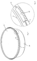
- Fig. 1 shows a perspective view of a first container 1.
- the first container 1 expediently has a cylindrical and upwardly conically widening shape. It is advantageously made of polypropylene.
- At the opening edge of the container 1 is a circumferential first U-profile 2 with an inner space facing the container inner leg 3 and the inner leg 3 concentrically surrounding second outer leg 4 is provided.
- the inner 3 and the second outer leg 4 are interconnected by a first base surface 5.
- a portion A of the second outer leg 4 is formed as a tearable first tab 6.
- Fig. 2 shows a sectional view through the first container 1 with the first lid mounted thereon 7.
- the first cover 7 at its edge a circumferential second U-profile 8.
- the second U-profile 8 has a further inner leg 9 and a first outer leg 10, which are connected to each other via a second base surface 11.
- the shape and the radius of the second base surface 11 corresponds approximately to the shape and the radius of the inner leg 3.
- a radially outwardly projecting first projection 12 has a to the first base surface indicative first inclined surface 13. From a inner wall of the first outer leg 10 extends radially inwardly a second projection 14.
- the second projection 14 has a second inclined surface 15, which extends approximately parallel to the first inclined surface 13.
- a tamper-evident ring 16 is attached via narrow material bridges (not shown here).
- the tamper-evident ring 16 has a larger radius than the first outer leg 10.
- Fig. 5 shows the sectional view according to Fig. 2 , This is the cutting position of the in Fig. 6 reproduced detailed view marked.
- Fig. 6 shows a cutting position outside of the section A through the first 2 and the second U-profile 8.
- a radially inwardly projecting third projection 17 which has a first base surface 5 extending towards the third inclined surface 19.
- the fourth projection 18 is here opposite the first tab 6.
- On an inner wall of the first tab 6 no projection corresponding to the fourth projection 18 is attached.
- the function of the in the Fig. 1 to 6 shown first plastic container is the following:
- the first lid 7 is inserted with its second U-profile 8 on the inner leg 3.
- the second projection 14 slides over the first projection 12, facilitated by a further oblique surface provided in the region of the inner circumferential edge.
- the fourth projection 18 is guided along the third inclined surface 19.
- the tamper-evident ring 16 is pressed radially inward.
- the fourth projection 18 of the tamper-evident ring 16 latches behind the third projection 17.
- the second projection 14 latches behind the first projection 12.
- the first U-profile 2 is opened in section A, so that the tamper-evident ring 16 and the first outer leg 10 of the first lid 7 are accessible.
- the tamper-evident ring 16 approximately in alignment with the edge regions of the section A has further predetermined breaking lines (not shown here). This makes it possible to remove a portion of the tamper-evident ring 16, for example a peripheral portion in the range of 30 to 50 °, and subsequently to attack directly on the first outer leg 10 in order to lift off the lid 7.
- the tamper-evident ring 16 is retained in the first U-profile 2.
- the base 5 may also have a recess in the region of the section A.
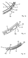
- the Fig. 7 to 10 show a second variant of the invention.
- the first U-profile 2 is again provided on a second container 20, but here omitting the first tab 6. That is, the second outer leg 4 is performed circumferentially without interruption.
- a second cover 21 in turn has a second U-profile 8.
- a radially outwardly projecting second tab 22 is molded, which extends over a limited portion. The second tab 22 engages over the second outer leg 4 of the first U-profile 2 in the closed state.
- the function of the second plastic container is as follows:
- the second lid 21 is placed in a manner analogous to the first lid 7 on the second container 20. For the first time Opening the second lid 21, it is only necessary to push the second tab 22 upwards. As a result, the tamper-evident ring 16 connecting to the first outer leg 10 (not shown here) material bridges are severed. The tamper-evident ring 16 is retained in the first U-profile 2 by the latch formed by the third 17 by cooperation with the fourth projection 18.
- the first plastic container is particularly suitable for use with automatic filling and capping devices. To its particular suitability contributes here that no radially beyond the first cover 7 protruding tabs, such as the second tab 22, are provided. However, it is also conceivable to operate the second plastic container 20 with automatic filling and capping devices.
- the FIGS. 11 and 12 show a third container 23.
- the first U-profile 2 has a second outer leg 4, from the inside of which third projections 17 extend radially inwardly.
- the third projections 17 are formed in the form of flexible latching tongues, the upper side of which are designed as curved to the first base surface 5 down, curved third inclined surfaces 19.
- Opposite the third projections 17 are provided on the inner leg 3 radially outwardly projecting guide means 24, which are similar to the third projections 17 in the form of flexible locking tongues with a sloping to the first base surface 5 second inclined surface 25 formed on its upper side.
- the third projections 17 and the opposite guide means 24 form an interrupted channel-like structure in the first U-profile 2.
- first tab 6 is connected to the second outer leg 4 via first film bridges 26.
- the first base surface 5 has a first opening 27 approximately along a circumferential section described by the first tab 6.
- the first tab 6 is connected to predetermined breaking webs 28 with the third container 23 and a portion of the first base surface 5, which span the first opening 27.
- Fig. 13 to 15 show further views of the first cover 7.
- the tamper-evident ring 16 has axially extending second film bridges 29 which form predetermined breaking lines. A distance between two adjacent second film bridges 29 is smaller than a distance between the z.
- Fig. 11 shown first film bridges 26 of the first tab 6.
- Fig. 15 It can be seen that the tamper-evident ring 16 is connected to the first outer leg 10 of the lid 7 via a first perforation P1.
- the Fig. 16 to 18 show a detail of a fourth container 30 in not inventive modification.
- the guide means 24 are formed in the form obliquely to the first base surface 5 down sloping webs, which are approximately opposite the third projections 17.
- the first base surface 5 below the third projections 17 second openings 31.
- a second perforation P2 is provided in the sections in which the second outer leg 4 is connected to the first base surface 5.
- the function of the fourth container 30 is as follows:
- the lid 7 is raised by pressing on the tamper-evident ring 16.
- the second perforation P2 tears.
- the second outer leg 4 is separated from the first U-profile 2 and lifted with the lid 7 fixedly mounted tamper-evident ring 16.
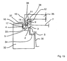
- Fig. 19 shows a partially schematic sectional view of a tool for automatically capping a container according to the invention, here by way of example the fourth container 30.
- the tool comprises a, preferably annular, receptacle 32 for receiving the container 30.
- the receptacle 32 has on its inner circumference a step-like, circumferential profile with a first support surface 33. On the first support surface 33, a radially outer portion of the first base surface 5 of the fourth container 30 is supported. Furthermore, the receptacle 32 has a second Stitz phenomenon.34 on which the formed in the fourth container 30 shoulder S is supported. Both the first 33 and the second support surface 34 extend substantially horizontally. They correspond in their vertical distance from the contour of the fourth container 30.
- the reference numeral 35 denotes a pressure element, which may be formed annular or in the manner of a disc. From a peripheral edge of the pressure element 35 extends a circumferential wall 36.
- the wall 36 has a stepped end face with a first pressure surface 37 for applying a pressure on the tamper-evident ring 16 on.
- the pressure element 35 has a second pressure surface 38 for exerting a pressure on the second base surface 11 of the second U-profile 8.
- the first 37 and second pressure surfaces 38 are substantially horizontal.
- a vertical distance between the first pressure surface 37 and the second pressure surface 38 is selected to be slightly larger than a vertical distance between an upper edge of the tamper-evident ring 16 and the second base surface 11. The difference may be 0.1 to 0.5 mm, preferably 0.2 to 0.4 mm.
- the function of the tool is the following:
- a container here, for example, the fourth container 30, inserted into the receptacle 32, so that the first base surface 5 rests with a radially outer portion on the first support surface 33 and at the same time the shoulder S on the second support surface 34.
- the first support surface 33 supports the first base surface 5 such that it overlaps preferably less than 50%, particularly preferably less than 40%, with the first support surface 33.
- a first lid 7 corresponding to the fourth container 30 is inserted into the first U-profile such that its tamper-evident ring 16 lies in a groove formed by the fourth projection 17 and the guide means 24.
- This can z. B. by means of the pressure element 35 by a frictional connection or an adhesive connection is made by means of negative pressure between the cover 7 and the pressure element 35.
- the pressure element 35 is moved relative to the receptacle 32 so that the first pressure surface 37 rests against the upper edge of the tamper-evident ring 16.
- the second pressure surface 38 is still not on the second base surface 11 at. It is then exerted by a further movement of the pressure element 35 relative to the receptacle 32, a pressure on the tamper-evident ring 16.
- the first U-profile 2 is tilted radially inwardly into the receptacle 32 due to its flexible material properties and as a result of the only partial support of the first base surface 5 on the first support surface 33. This facilitates the latching of the tamper-evident ring 16 behind the third projection 17.
- the second pressure surface 38 then comes into contact with the second base surface 11, whereby a locking of the first 12 and the second projection 14 is supported.
- first base surface 5 is only partially supported on the first support surface 33. It is also possible to support the first base surface 4 substantially over the entire area on the first support surface 33. Likewise, it is of course also possible to change the arrangement of the first 37 and the second pressure surface 38 in their vertical distance, so that they correspond to the contour of the lid 7. - However, it has been shown that with the in Fig. 19 illustrated embodiment of the tool a particularly secure and reliable automatic cover of the container according to the invention can be achieved.
Abstract
Description
Die Erfindung betrifft einen Kunststoffbehälter zur Aufnahme von Lebensmitteln nach dem Oberbegriff des Anspruchs 1.The invention relates to a plastic container for holding food according to the preamble of
Ein derartiger Kunststoffbehälter ist beispielsweise aus der
Die
Bei dem bekannten Kunststoffbehälter ist am Öffnungsrand des Behälters ein umlaufendes erstes U-Profil vorgesehen. Das erste U-Profil weist einen zum Behälterinnenraum gewandten inneren Schenkel auf, an dem ein erstes Rastmittel, beispielsweise ein radial nach außen vorspringender, umlaufender erster vorsprung, vorgesehen ist. Am Rand des Deckels ist ein umlaufendes zweites U-Profil vorgesehen. Ein durch das zweite U-Profil gebildeter umlaufender Schlitz ist von seinem Durchmesser her so bemessen, dass der innere Schenkel des ersten U-Profils darin eingesteckt werden kann. Am ersten äußeren Schenkel des zweiten U-Profils ist ein zweites Rastmittel vorgesehen, welches mit dem ersten Rastmittel korrespondiert. Es kann sich dabei um einen vom zweiten äußeren Schenkel radial nach innen vorspringenden, umlaufenden zweiten Vorsprung handeln. Beim Aufsetzen des Deckels verrasten die Rastmittel miteinander. Gleichzeitig wird ein umlaufender Rand des ersten äußeren Schenkels des Deckels im ersten U-Profil des Behälters aufgenommen, so dass er zu öffnungszwecken nicht nach oben gedrückt werden kann. Zum Öffnen des mit dem Deckel verschlossenen Behälters ist es erforderlich, einen perforierten Abschnitt, welcher an einem zweiten äußeren Schenkel des ersten U-Profils vorgesehen ist, abzureißen. Erst dann ist der Umfangsrand des ersten äußeren Schenkels des zweiten U-Profils des Deckels zugänglich und der Deckel kann geöffnet werden.In the known plastic container, a circumferential first U-profile is provided at the opening edge of the container. The first U-profile has an inner leg facing the container interior, on which a first latching means, for example, a radially outwardly projecting, circumferential first projection, is provided. At the edge of the lid, a circumferential second U-profile is provided. A circumferential slot formed by the second U-profile is dimensioned from its diameter such that the inner leg of the first U-profile can be inserted therein. At the first outer leg of the second U-profile, a second locking means is provided, which corresponds to the first locking means. It may be a circumferential from the second outer leg radially inwardly, circumferential second projection. When placing the lid, the locking means lock together. At the same time a peripheral edge of the first outer leg of the lid is received in the first U-profile of the container so that it can not be pushed upwards for opening purposes. To open the lid closed Container is required to tear a perforated portion which is provided on a second outer leg of the first U-profile. Only then is the peripheral edge of the first outer leg of the second U-profile of the lid accessible and the lid can be opened.
Theoretisch ist es denkbar, den Deckel auch unter Verwendung eines geeigneten Werkzeugs abzuheben, ohne dass der perforierte Abschnitts am zweiten äußeren Schenkel entfernt wird. Infolgedessen ist es theoretisch auch denkbar, dass Unbefugte den Deckel abheben, unbemerkt Ware aus dem Behälter entfernen oder verändern und nachfolgend den Behälter wieder mit einem Deckel verschließen. Um diesem Nachteil entgegenzuwirken, sind einige Hersteller dazu übergegangen, die Verbindung zwischen dem Deckel und dem Behälter zusätzlich durch eine aufgeschrumpfte Folie zu sichern. Das erfordert allerdings einen zusätzlichen Herstellungsaufwand. Abgesehen davon wird dadurch das Öffnen des Behälters für den verbraucher weiter erschwert.Theoretically, it is conceivable to lift the lid using a suitable tool without removing the perforated section on the second outer leg. As a result, it is also theoretically conceivable that unauthorized persons lift off the lid, unnoticed to remove or change goods from the container and subsequently close the container again with a lid. To counteract this disadvantage, some manufacturers have begun to secure the connection between the lid and the container in addition by a shrunk on film. However, this requires an additional manufacturing effort. Apart from this, the opening of the container for the consumer is further complicated.
Aufgabe der Erfindung ist es, die Nachteile nach dem Stand der Technik zu beseitigen. Es soll insbesondere ein möglichst einfach und kostengünstig herstellbarer Kunststoffbehälter mit verbesserter Originalitätssicherung angegeben werden. Nach einem weiteren Ziel der Erfindung soll der Kunststoffbehälter für den Verbraucher möglichst einfach zu öffnen sein. Schließlich soll jederzeit erkennbar sein, ob der Behälter bereits schon einmal geöffnet worden ist oder nicht.The object of the invention is to eliminate the disadvantages of the prior art. It should in particular be given a simple and inexpensive to produce plastic container with improved tamper evidence. According to a further object of the invention, the plastic container should be as easy as possible to open for the consumer. Finally, it should always be recognizable whether the container has already been opened before or not.
Diese Aufgabe wird durch die Merkmale des Anspruchs 1 gelöst. Zweckmäßige Ausgestaltungen der Erfindung ergeben sich aus den Merkmalen der Ansprüche 2 bis 21.This object is solved by the features of
Im Sinne der vorliegenden Erfindung wird unter dem Begriff "Originalitätssicherungsring" ein am Deckel vorgesehener Ring verstanden, der beim erstmaligen Öffnen des Deckels im ersten U-Profil zurückgehalten wird. Ein wesentliches Merkmal des Originalitätssicherungsrings besteht darin, dass dieser nach einem erstmaligen öffnen des Deckels nicht mehr mit dem Behälter verrastet werden kann.For the purposes of the present invention, the term "tamper-evident ring" is understood to mean a ring provided on the cover which is retained in the first U-profile when the cover is first opened. An essential feature of the tamper evident ring is that it can not be locked to the container after a first opening of the lid.
Nach Maßgabe der Erfindung ist vorgesehen, dass der Originalitätssicherungsring eine Vielzahl axial verlaufender dritter Sollbruchlinien aufweist. - Das Vorsehen solcher dritter Sollbruchlinien ermöglicht einerseits ein abschnittsweises Abreißen des Originalitätssicherungsrings. Anderseits wird damit die Flexibilität des Originalitätssicherungsrings erhöht, wodurch ein Verrasten desselben im ersten U-Profil erleichtert wird.According to the invention it is provided that the tamper-evident ring has a plurality of axially extending third predetermined breaking lines. - The provision of such third predetermined breaking lines enables on the one hand a partial tearing of the tamper evident ring. On the other hand, it increases the flexibility of the tamper-evident ring, which makes it easier to lock it in the first U-profile.
Der vorgeschlagene Kunststoffbehälter lässt sich einfach herstellen. Sowohl der Behälter als auch der Deckel können in herkömmlicher Weise jeweils in einem Schuss mittels spritzguss hergestellt werden. Das Öffnen des Kunststoffbehälters kann durch die Verbraucher in herkömmlicher weise erfolgen. Es ist insbesondere nicht das Entfernen einer zusätzlichen aufgeschrumpften Kunststofffolie erforderlich. Infolge des Öffnens des Behälters reißt der am Deckel vorgesehene Originalitätssicherungsring zumindest abschnittsweise ab. Damit kann der Verbraucher sofort erkennen, ob der Behälter zuvor bereits schon einmal geöffnet worden ist.The proposed plastic container is easy to produce. Both the container and the lid can be produced in a conventional manner each in a shot by means of injection molding. The opening of the plastic container can be done by the consumer in a conventional manner. In particular, it is not necessary to remove an additional shrunk-on plastic film. As a result of the opening of the container, the tamper-evident ring provided on the cover breaks off at least in sections. This allows the consumer to immediately recognize whether the container has been previously opened before.
Unter dem Begriff "umlaufend" wird im Sinne der vorliegenden Erfindung verstanden, dass die jeweiligen U-Profile und/oder die erste Sollbruchlinie sich über einen Umfangswinkel von zumindest 270°, vorzugsweise zumindest 300°, besonders bevorzugt 310 bis 330°, oder auch über den gesamten Umfang, d. h. 360°, erstrecken. Der Originalitätssicherungsring kann am Deckel sich mit dessen gesamten Umfang erstrecken. Er kann allerdings Schwächungslinien aufweisen, so dass beim Abreißen des Originalitätssicherungsrings beispielsweise ein Umfangsabschnitt von etwa 320° ± 10° im ersten U-Profil zurückgehalten wird. Ein verbleibender weiterer Umfangsabschnitt kann zur Erleichterung eines erstmaligen Abhebens des Deckels zuvor separat vom Originalitätssicherungsring getrennt werden.For the purposes of the present invention, the term "circumferential" is understood to mean that the respective U-profiles and / or the first predetermined breaking line extending over a circumferential angle of at least 270 °, preferably at least 300 °, more preferably 310 to 330 °, or over the entire circumference, ie 360 ° extend. The tamper-evident ring can extend on the cover with its entire circumference. However, it may have weakening lines, so that when tearing off the tamper evident ring, for example, a peripheral portion of about 320 ° ± 10 ° is retained in the first U-profile. A remaining further peripheral portion may be separately separated from the tamper-evident ring to facilitate initial lifting of the lid.
Nach einer vorteilhaften Ausgestaltung ist das erste Rastmittel ein von einer Außenwand des inneren Schenkels nach außen vorspringender umlaufender erster Vorsprung, und das zweite Rastmittel ist ein von einer Innenwand des ersten äußeren Schenkels des zweiten U-Profils radial nach innen vorspringender zweiter Vorsprung. Der erste und der zweite Vorsprung können zueinander korrespondierende Schrägflächen aufweisen, so dass beim Abheben des Deckels vom Behälter der erste äußere Schenkel nach außen gebogen und damit die durch den ersten und den zweiten Vorsprung gebildete Verrastung gelöst wird.According to an advantageous embodiment, the first latching means is a projecting from an outer wall of the inner leg outwardly circumferential first projection, and the second latching means is a radially projecting from an inner wall of the first outer leg of the second U-profile second projection. The first and the second projection may have mutually corresponding inclined surfaces, so that when lifting the lid from the container, the first outer leg is bent outwards and thus the latch formed by the first and the second projection is released.
Nach einer weiteren Ausgestaltung der Erfindung ist vorgesehen, dass das erste U-Profil einen den inneren Schenkel konzentrisch umgebenden zweiten äußeren Schenkel aufweist, und wobei das dritte Rastmittel ein von einer Innenwand des zweiten äußeren Schenkels radial nach innen vorspringender dritter Vorsprung ist. Bei dem dritten Rastmittel kann es sich beispielsweise um flexible Rastzungen handeln, welche sich von der Innenwand des zweiten äußeren Schenkels im Bereich des oberen Umfangsrands radial schräg in Richtung einer ersten Basisfläche des ersten U-Profils erstrecken. Beim Aufsetzen des Deckels können derartige Rastzungen in Richtung der Innenwand des zweiten äußeren Schenkels gebogen und nachfolgend kann das vierte Rastmittel durch Zurückschnappen der Rastzungen mit dem ersten U-Profil verrastet werden.According to a further embodiment of the invention, it is provided that the first U-profile has a second outer leg concentrically surrounding the inner leg, and wherein the third latching means is a third projection projecting radially inwardly from an inner wall of the second outer leg. The third latching means may, for example, be flexible latching tongues which extend radially obliquely from the inner wall of the second outer leg in the region of the upper peripheral edge in the direction of a first base surface of the first U-profile. When placing the lid such locking tongues in the direction of Inner wall of the second outer leg bent and subsequently the fourth locking means can be locked by snapping back the locking tongues with the first U-profile.
Das vierte Rastmittel kann ein vom Umfangsrand des originalitätssicherungsrings nach außen vorspringender, umlaufender vierter Vorsprung sein. Der vierte vorsprung kann in Form von Vorsprüngen ausgebildet sein, welche sich abschnittsweise über vorgegebene Umfangsabschnitte erstrecken. Solche abschnittsweisen vierten vorsprünge können sich beispielsweise um Umfangswinkel von 15 bis 30° erstrecken und durch eine V-förmige Einkerbung voneinander abgesetzt sein. Das erleichtert das Aufsetzen des Deckels, insbesondere das Verrasten des Originalitätssicherungsrings mit dem ersten U-Profil.The fourth locking means may be a circumferential fourth projection projecting outwardly from the peripheral edge of the tamper evident ring. The fourth projection may be formed in the form of projections, which extend in sections over predetermined peripheral portions. Such sectional fourth projections may, for example, extend around circumferential angles of 15 to 30 ° and be offset from each other by a V-shaped notch. This facilitates the placement of the lid, in particular the locking of the tamper evident ring with the first U-profile.
Vorteilhafterweise weist der innere Schenkel gegenüber einer Basisfläche des ersten U-Profils eine größere Höhe auf als der zweite äußere Schenkel. Das erleichtert das Aufstecken des zweiten U-Profils auf den inneren Schenkel des ersten U-Profils. Selbstverständlich entspricht in der Draufsicht die Form des inneren Schenkels etwa der Form des durch das zweite U-Profil gebildeten Schlitzes, so dass der Deckel auf den inneren Schenkel aufgesteckt werden kann.Advantageously, the inner leg relative to a base surface of the first U-profile has a greater height than the second outer leg. This facilitates the attachment of the second U-profile on the inner leg of the first U-profile. Of course, in the plan view corresponds to the shape of the inner leg about the shape of the slot formed by the second U-profile, so that the lid can be attached to the inner leg.
Nach einer weiteren Ausgestaltung der Erfindung ist vorgesehen, dass das erste Rastmittel bezüglich der Basisfläche in einen größeren Abstand als das dritte Rastmittel vorgesehen ist, und wobei das vierte Rastmittel bezüglich einer zweiten Basisfläche des zweiten U-Profils in einem größeren Abstand als das zweite Rastmittel vorgesehen ist. Dabei befinden sich das erste und das zweite Rastmittel in einem ersten radialen Abstand und das dritte und das vierte Rastmittel in einem zweiten radialen Abstand, welcher größer als der erste radiale Abstand ist. Infolgedessen gelingt es, beim Aufsetzen des Deckels mehr oder weniger gleichzeitig das erste und das zweite Rastmittel sowie das dritte und das vierte Rastmittel in Anlage zu bringen und durch einen nachfolgenden Druck auf den Deckel eine verrastung zwischen dem ersten und dem zweiten sowie dem dritten und dem vierten Rastmittel herzustellen. Dabei ist die zwischen dem ersten und dem zweiten Rastmittel hergestellte Verrastung lösbar, wohingegen die zwischen dem dritten und dem vierten Rastmittel hergestellte Verrastung unlösbar ist, so dass beim Öffnen des Deckels der Originalitätssicherungsring bzw. der zweite äußere Schenkel zumindest abschnittsweise abreißt.According to a further embodiment of the invention it is provided that the first locking means is provided with respect to the base surface at a greater distance than the third locking means, and wherein the fourth locking means provided with respect to a second base surface of the second U-profile at a greater distance than the second locking means is. In this case, the first and the second latching means are at a first radial distance and the third and the fourth latching means at a second radial distance, which is greater than the first radial distance. As a result, it succeeds in placing the lid more or less simultaneously, the first and the second catch means and bring the third and the fourth latching means in abutment and to produce by a subsequent pressure on the lid a latching between the first and the second and the third and the fourth latching means. In this case, the latching produced between the first and the second latching means is releasable, whereas the latching produced between the third and the fourth latching means is insoluble, so that when opening the lid tearing off the tamperproof ring or the second outer leg at least in sections.
Um die Herstellung einer Verrastung zwischen dem dritten und dem vierten Rastmittel zu erleichtern, ist zweckmäßigerweise vorgesehen, dass das dritte Rastmittel eine zur ersten Basisfläche hin abfallende erste Schrägfläche aufweist. Beim Aufsetzen des Deckels wird durch die vorgeschlagene Schrägfläche das am Originalitätssicherungsring vorgesehene vierte Rastmittel radial nach innen gedrückt und kann somit einfach in eine nachfolgend herzustellende verrastete Position gebracht werden.In order to facilitate the production of a latching between the third and the fourth latching means, it is expediently provided that the third latching means has a first inclined surface sloping down towards the first base surface. When placing the lid is provided by the proposed inclined surface provided on the tamper evident ring fourth detent means radially inwardly and can thus be easily brought into a subsequently produced latched position.
Nach einer vorteilhaften Ausgestaltung ist am inneren Schenkel in einer dem dritten Rastmittel etwa gegenüberliegenden Anordnung ein radial nach außen vorspringendes Führungsmittel vorgesehen, welches eine zur ersten Basisfläche hin abfallende zweite Schrägfläche aufweist. Das dritte Rastmittel und das Führungsmittel sind zweckmäßigerweise in Form flexibler Rastzungen ausgebildet. Derart ausgebildete Rastzungen bilden abschnittsweise mit ihren ersten und zweiten Schrägflächen Rinnen, welche beim Eindrücken des Originalitätssicherungsrings sich aufweiten und bei vollständig eingedrücktem Originalitätssicherungsring diesen verrasten. Die Anordnung der einander gegenüberliegenden Führungsmittel und dritten Rastmittel bewirkt eine Selbstzentrierung des aufgesetzten Originalitätssicherungsrings. Sie erleichtert wesentlich eine automatische, maschinelle Bedeckung der Behälter.According to an advantageous embodiment, a radially outwardly projecting guide means is provided on the inner leg in a third latching means approximately opposite arrangement, which has a sloping towards the first base surface second inclined surface. The third locking means and the guide means are expediently in the form of flexible locking tongues. Such trained locking tongues form sections with their first and second inclined surfaces grooves, which widen when pressing the tamper-evident ring and lock this completely pressed in tamper-evident ring. The arrangement of the opposing guide means and third locking means causes a self-centering of the attached tamper evident ring. It substantially facilitates automatic, machine-covering of the containers.
Nach einer weiteren Ausgestaltung der Erfindung ist vorgesehen, dass bei mit dem Behälter verrastetem Deckel der Originalitätssicherungsring vom zweiten äußeren Schenkel abgedeckt wird. Damit wird eine Manipulation des Originalitätssicherungsrings vermieden. Es kann jederzeit sicher und zuverlässig die Originalität der im Behälter aufgenommenen Ware angezeigt werden.According to a further embodiment of the invention it is provided that is covered with the container latched lid of the tamper-evident ring from the second outer leg. This avoids manipulation of the tamper evident ring. It can be displayed at any time safely and reliably the originality of the goods received in the container.
Vorteilhafterweise ist ein erster Außenradius des ersten äußeren Schenkels um höchstens 2,5 mm, vorzugsweise höchstens 1,5 mm, kleiner als ein zweiter Außenradius des Originalitätssicherungsrings. Indem der erste äußere Schenkel radial nur in einem relativ kleinen Abstand vom inneren Schenkel vorgesehen ist, wird eine besonders hohe Steifigkeit der Konstruktion erreicht, so dass der Originalitätssicherungsring besonders sicher und zuverlässig mit dem ersten U-Profil verrastbar ist.Advantageously, a first outer radius of the first outer leg is at most 2.5 mm, preferably at most 1.5 mm, smaller than a second outer radius of the tamper-evident ring. By the first outer leg is provided radially only at a relatively small distance from the inner leg, a particularly high rigidity of the construction is achieved, so that the tamper evident ring is particularly safe and reliable latched to the first U-profile.
Zweckmäßigerweise weist ein erster Abschnitt des zweiten äußeren Schenkels eine zweite Sollbruchlinie auf, so dass im zweiten äußeren Schenkel eine erste Ausnehmung herstellbar ist. Dabei weist zweckmäßigerweise die erste Basisfläche im Bereich des ersten Abschnitts eine zweite Ausnehmung auf. Der erste Abschnitt kann durch die zweite Ausnehmung überspannende Sollbruchstege mit der ersten Basisfläche und/oder dem inneren Schenkel verbunden sein. Damit wird ein versehentliches Abreißen des ersten Abschnitts, beispielsweise beim Stapeln oder beim Transport, verhindert.Expediently, a first section of the second outer leg has a second predetermined breaking line, so that a first recess can be produced in the second outer leg. In this case, the first base surface expediently has a second recess in the region of the first portion. The first portion may be connected by the second recess spanning breaking webs with the first base surface and / or the inner leg. This prevents inadvertent tearing off of the first section, for example during stacking or during transport.
Nach einer weiteren Ausgestaltung sind die axial verlaufenden dritten Sollbruchlinien des Originalitätssicherungsrings regelmäßig voneinander beabstandet.According to a further embodiment, the axially extending third predetermined breaking lines of the tamper evident ring are regularly spaced from each other.
Zweckmäßigerweise ist ein Umfangsabschnitt zwischen zwei benachbarten dritten Sollbruchlinien kleiner als die zweite Ausnehmung. Das erleichtert ein abschnittsweises Abreißen des Originalitätssicherungsrings.Conveniently, a peripheral portion between two adjacent third predetermined breaking lines is smaller than the second recess. This facilitates a section-wise tearing of the tamper evident ring.
Durch das Entfernen des ersten Abschnitts wird für den Verbraucher eine Unterkante des ersten äußeren Schenkels des zweiten U-Profils bzw. der Originalitätssicherungsring zugänglich. Zum Öffnen des Deckels kann der Verbraucher nunmehr daran, beispielsweise mit dem Daumen ansetzen, diesen nach oben drücken, so dass der Originalitätssicherungsring abreißt und der Deckel geöffnet werden kann. Durch das Vorsehen des abreißbaren ersten Abschnitts sowie des Originalitätssicherungsrings wird eine besonders sichere und zuverlässige doppelte Originalitätssicherung zur Verfügung gestellt.By removing the first portion, a lower edge of the first outer leg of the second U-profile or the tamper evident ring becomes accessible to the consumer. To open the lid, the consumer can now attach it, for example with the thumb, push it upwards, so that the tamper evident ring breaks off and the lid can be opened. By providing the tearable first section and the tamper-evident ring provide a particularly secure and reliable double tamper evidence.
Nach einer weiteren zweckmäßigen Ausgestaltung ist die erste Sollbruchlinie als Perforation ausgebildet. D. h. der Originalitätssicherungsring ist über schmale Materialbrücken mit dem Deckel verbunden, so dass er ohne großen Kraftaufwand vom Deckel getrennt werden kann.According to a further expedient embodiment, the first predetermined breaking line is formed as a perforation. Ie. The tamper evident ring is connected to the lid via narrow bridges of material so that it can be separated from the lid without much effort.
Die zweiten und/oder dritten Sollbruchlinien sind zweckmäßigerweise als durchgehende Filmbrücken ausgebildet. Sie können aber auch ähnlich der ersten Sollbruchlinie als Perforation ausgebildet sein.The second and / or third predetermined breaking lines are expediently designed as continuous film bridges. But they can also be designed as a perforation similar to the first predetermined breaking line.
Der Behälter und der Deckel sind nach einer weiteren Ausgestaltung aus einem flexiblen Kunststoff, vorzugsweise Polypropylen, hergestellt. Sowohl der Deckel und der Behälter sind vorteilhafterweise so gestaltet, dass sie jeweils in einem Schuss mittels Spritzguss hergestellt werden können.The container and the lid are made according to another embodiment of a flexible plastic, preferably polypropylene. Both the lid and the container are advantageously designed so that they can be produced in one shot by means of injection molding.
Nach einer weiteren Ausgestaltung ist vorgesehen, dass der Deckel in einer vom Behälter abweichenden Farbe hergestellt ist. Damit kann z. B. der vom Deckel abgerissene und im ersten U-Profil zurückgehaltene Originalitätssicherungsring leicht erkannt werden. Es kann also auf einem Blick festgestellt werden, ob der Deckel schon einmal vom Behälter gelöst worden ist.According to a further embodiment it is provided that the lid is made in a different color from the container. This can z. B. the torn off from the lid and retained in the first U-profile tamper evident ring easily. So it can be stated at a glance whether the lid has ever been detached from the container.
Der Behälter kann eine zylindrische und/oder nach oben sich konisch erweiternde Form aufweisen. Er kann aber auch rechteckig oder andersartig geformt sein.The container may have a cylindrical and / or upwardly conically widening shape. But it can also be rectangular or otherwise shaped.
Der erfindungsgemäße Behälter weist in einer vorteilhaften Ausgestaltung in Kombination mit dem Deckel eine besonders sichere doppelte Originalitätssicherung auf. Zum Öffnen des Deckels ist es erforderlich, zunächst die erste Lasche abzureißen (erste Originalitätssicherungsstufe) und nachfolgend durch Anheben des Deckels den Originalitätssicherungsring abzureißen (zweite Originalitätssicherungsstufe).The container according to the invention in an advantageous embodiment in combination with the lid on a particularly secure double tamper evidence. To open the lid it is necessary to first tear off the first tab (first tamper-evident level) and subsequently tear off the tamper-evident ring by lifting the lid (second tamper-evident level).
Abgesehen davon lässt sich der erfindungsgemäße Behälter vorteilhafterweise einfach automatisch bedeckeln. Insoweit haben sich folgende Verfahrensschritte als vorteilhaft erwiesen:
- Bereitstellen eines erfindungsgemäßen Behälters sowie eines dazu korrespondierenden erfindungsgemäßen Deckels,
- Zuführen des Behälters zu einer Aufnahmeeinrichtung, in welcher der Behälter im Bereich der ersten Basisfläche abgestützt wird;
- Aufsetzen des Deckels auf den Behälter, so dass der Originalitätssicherungsring in
das erste U-Profil 2 eingreift; und - Ausüben eines Drucks auf einen durch das zweite U-Profil gebildeten umlaufenden Rand des Deckels, so dass die ersten und die zweiten Rastmittel sowie die dritten und die vierten Rastmittel miteinander verrasten.
- Providing a container according to the invention and a corresponding lid according to the invention,
- Feeding the container to a receiving device, in which the container is supported in the region of the first base surface;
- Placing the lid on the container so that the tamper evident ring engages the first U-profile 2; and
- Applying a pressure to a peripheral edge of the lid formed by the second U-profile so that the first and the second locking means and the third and fourth locking means lock together.
Indem der Behälter im Bereich der ersten Basisfläche abgestützt und ein Druck auf den durch das zweite U-Profil gebildeten Rand ausgeübt wird, wird eine unerwünschte Verformung des Materials weitgehend vermieden und damit eine besonders zuverlässige und störungsfreie automatische Bedeckelung erreicht. Insbesondere wird nach dem vorgeschlagenen Verfahren der Druck zum Verrasten des Deckels nur in solchen Bereichen ausgeübt, welche auf Grund der vorgesehenen U-Profile relativ steif ausgebildet sind.By supporting the container in the region of the first base surface and exerting a pressure on the edge formed by the second U-profile, an undesired deformation of the material is largely avoided and thus a particularly reliable and trouble-free automatic cover is achieved. In particular, according to the proposed method, the pressure for latching the lid is exerted only in those areas which are relatively stiff due to the provided U-profiles.
Nachfolgend werden Ausführungsbeispiele der Erfindung anhand der Zeichnungen näher erläutert. Es zeigen:
- Fig. 1
- eine perspektivische Ansicht eines ersten Behäl- ters,
- Fig. 2
- eine Schnittansicht durch den Behälter gemäß
Fig. 1 mit Deckel, - Fig. 3
- eine Detailansicht gemäß
Fig. 2 , - Fig. 4
- eine Seitenansicht auf den Behälter gemäß
Fig. 2 , - Fig. 5
- die Schnittansicht gemäß
Fig. 4 mit eingezeichneter Lage der inFig. 6 gezeigten Detailansicht, - Fig. 6
- Detailansicht gemäß
Fig. 5 , - Fig. 7
- eine perspektivische Ansicht eines zweiten Behäl- ters,
- Fig. 8
- eine Detailansicht gemäß
Fig. 7 , - Fig. 9
- eine Schnittansicht durch den zweiten Behälter mit aufgesetztem Deckel,
- Fig. 10
- eine Detailansicht gemäß
Fig. 9 , - Fig. 11
- eine perspektivische Teilansicht eines dritten Be- hälters,
- Fig. 12
- eine Draufsicht gemäß
Fig. 11 , - Fig. 13
- eine perspektivische Ansicht eines dritten Deckels,
- Fig. 14
- eine perspektivische Detailansicht gemäß
Fig. 13 , - Fig. 15
- eine Draufsicht gemäß
Fig. 13 , - Fig. 16
- eine perspektivische Teilansicht eines vierten Be- hälters, in nicht erfindungsgemäßer Abwandlung,
- Fig. 17
- eine Draufsicht gemäß
Fig. 16 , - Fig. 18
- eine perspektivische Unteransicht gemäß
Fig. 16 und - Fig. 19
- eine schematische Schnittansicht durch ein Werkzeug zum automatischen Bedeckeln eines erfindungsgemäßen Behälters.
- Fig. 1
- a perspective view of a first container,
- Fig. 2
- a sectional view through the container according to
Fig. 1 with lid, - Fig. 3
- a detailed view according
Fig. 2 . - Fig. 4
- a side view of the container according to
Fig. 2 . - Fig. 5
- the sectional view according to
Fig. 4 with marked location of inFig. 6 shown detail view, - Fig. 6
- Detailed view according to
Fig. 5 . - Fig. 7
- a perspective view of a second container,
- Fig. 8
- a detailed view according
Fig. 7 . - Fig. 9
- a sectional view through the second container with attached lid,
- Fig. 10
- a detailed view according
Fig. 9 . - Fig. 11
- 3 is a partial perspective view of a third container,
- Fig. 12
- a plan view according to
Fig. 11 . - Fig. 13
- a perspective view of a third lid,
- Fig. 14
- a detailed perspective view according to
Fig. 13 . - Fig. 15
- a plan view according to
Fig. 13 . - Fig. 16
- 3 is a partial perspective view of a fourth container, not according to the invention,
- Fig. 17
- a plan view according to
Fig. 16 . - Fig. 18
- a perspective bottom view according to
Fig. 16 and - Fig. 19
- a schematic sectional view through a tool for automatically covering a container according to the invention.
Wie aus
Die Funktion des in den
Zum erstmaligen Verschließen des ersten Behälters 1 wird der erste Deckel 7 mit seinem zweiten U-Profil 8 auf den inneren Schenkel 3 gesteckt. Dabei gleitet der zweite Vorsprung 14 - erleichtert durch eine daran im Bereich des inneren Umfangsrands vorgesehene weitere Schrägfläche - über den ersten Vorsprung 12. Gleichzeitig wird der vierte Vorsprung 18 entlang de dritten Schrägfläche 19 geführt. Dabei wird der Originalitätssicherungsring 16 radial nach innen gedrückt. Schließlich verrastet der vierte Vorsprung 18 des Originalitätssicherungsrings 16 hinter dem dritten Vorsprung 17. Gleichzeitig verrastet der zweite Vorsprung 14 hinter dem ersten Vorsprung 12.For the first time closing of the
Zum erstmaligen Abheben des Deckels 7 wird vom Verbraucher die mittels einer ersten Perforation am zweiten äußeren Schenkel 4 vorgesehene erste Lasche 6 abgerissen. Wie insbesondere aus den
Die
Die Funktion des zweiten Kunststoffbehälters ist folgende:The function of the second plastic container is as follows:
Der zweite Deckel 21 wird in analoger Weise wie der erste Deckel 7 auf den zweiten Behälter 20 aufgesetzt. Zum erstma ligen Öffnen des zweiten Deckels 21 ist es lediglich erforderlich, die zweite Lasche 22 nach oben zu drücken. Infolgedessen werden die den Originalitätssicherungsring 16 mit dem ersten äußeren Schenkel 10 verbindenden (hier nicht gezeigten) Materialbrücken durchtrennt. Der Originalitätssicherungsring 16 wird durch die durch den dritten 17 durch Zusammenwirken mit dem vierten Vorsprung 18 gebildete Verrastung im ersten U-Profil 2 zurückgehalten.The
Im Rahmen der vorliegenden Erfindung ist es selbstverständlich möglich, die in den Ausführungsbeispielen gezeigten Vorsprünge andersartig anzuordnen oder auszubilden, so dass eine Verrastung erreicht werden kann.In the context of the present invention, it is of course possible to arrange or form the projections shown in the embodiments differently, so that a locking can be achieved.
Der erste Kunststoffbehälter eignet sich insbesondere zur Verwendung mit automatischen Befüll- und Bedeckelungsvorrichtungen. Zu seiner besonderen Eignung trägt hier bei, dass keine radial über den ersten Deckel 7 hinausstehenden Laschen, wie beispielsweise die zweite Lasche 22, vorgesehen sind. Es ist aber auch denkbar, den zweiten Kunststoffbehälter 20 mit automatischen Befüll- und Bedeckelungsvorrichtungen zu betreiben.The first plastic container is particularly suitable for use with automatic filling and capping devices. To its particular suitability contributes here that no radially beyond the
Die
Insbesondere aus
Die
Die
Wie insbesondere aus den
Die Funktion des vierten Behälters 30 ist Folgende:The function of the
Ein Deckel 7, bei dem der Originalitätssicherungsring 16 ohne erste Perforation P1, d. h. fest, angebracht ist, wird im ersten U-Profil 2 des vierten Behälters 30 verrastet. Dabei verrastet - ähnlich wie beim ersten bis dritten Behälter - der am Originalitätssicherungsring 16 vorgesehene vierte Vorsprung 18 hinter dem dritten Vorsprung 17. Nach dem Entfernen der ersten Lasche 6 wird der Deckel 7 durch Drücken auf den Originalitätssicherungsring 16 angehoben. Dabei reißt die zweite Perforation P2. Der zweite äußere Schenkel 4 wird vom ersten U-Profil 2 getrennt und mit dem am Deckel 7 fest angebrachten Originalitätssicherungsring 16 abgehoben.A
Mit dem Bezugszeichen 35 ist ein Druckelement bezeichnet, welches ringförmig oder nach Art einer Scheibe ausgebildet sein kann. Von einem umlaufenden Rand des Druckelements 35 erstreckt sich eine umlaufende Wand 36. Die Wand 36 weist eine stufenförmig ausgebildete Stirnfläche mit einer ersten Druckfläche 37 zum Ausüben eines Drucks auf den Originalitätssicherungsring 16 auf. Ferner weist das Druckelement 35 eine zweite Druckfläche 38 zum Ausüben eines Drucks auf die zweite Basisfläche 11 des zweiten U-Profils 8 auf. Die erste 37 und die zweite Druckfläche 38 verlaufen im Wesentlichen horizontal. Ein vertikaler Abstand zwischen der ersten Druckfläche 37 und der zweiten Druckfläche 38 ist geringfügig größer gewählt, als ein vertikaler Abstand zwischen einer Oberkante des Originalitätssicherungsrings 16 und der zweiten Basisfläche 11. Die Differenz kann 0,1 bis 0,5 mm, vorzugsweise 0,2 bis 0,4 mm, betragen.The
Die Funktion des Werkzeugs ist Folgende:The function of the tool is the following:
Zunächst wird ein Behälter, hier beispielsweise der vierte Behälter 30, in die Aufnahme 32 eingelegt, so dass die erste Basisfläche 5 mit einem radial äußeren Abschnitt auf der ersten Stützfläche 33 und gleichzeitig die Schulter S auf der zweiten Stützfläche 34 aufliegt. Die erste Stützfläche 33 stützt die erste Basisfläche 5 so ab, dass sie vorzugsweise zu weniger als 50%, besonders bevorzugt zu weniger als 40%, mit der ersten Stützfläche 33 überlappt.First, a container, here, for example, the
In einem nächsten Schritt wird ein zum vierten Behälter 30 korrespondierender erster Deckel 7 so in das erste U-Profil eingelegt, dass dessen Originalitätssicherungsring 16 in einer durch den vierten Vorsprung 17 und dem Führungsmittel 24 gebildeten Rinne liegt. Das kann z. B. mit Hilfe des Druckelements 35 erfolgen, indem zwischen dem Deckel 7 und dem Druckelement 35 eine reibschlüssige Verbindung oder eine Haftverbindung mittels Unterdruck hergestellt wird.In a next step, a
In einem weiteren Schritt wird das Druckelement 35 relativ zur Aufnahme 32 so verfahren, dass die erste Druckfläche 37 an der Oberkante des Originalitätssicherungsrings 16 anliegt. Zu diesem Zeitpunkt liegt die zweite Druckfläche 38 noch nicht an der zweiten Basisfläche 11 an. Es wird sodann durch eine weitere Bewegung des Druckelements 35 relativ zur Aufnahme 32 ein Druck auf den Originalitätssicherungsring 16 ausgeübt. Dabei wird das erste U-Profil 2 infolge seiner flexiblen Materialeigenschaften und infolge der lediglich teilweisen Abstützung der ersten Basisfläche 5 auf die erste Stützfläche 33 radial einwärts in die Aufnahme 32 verkippt. Das erleichtert das Verrasten des Originalitätssicherungsrings 16 hinter den dritten Vorsprung 17. Im weiteren Verlauf des Druckvorgangs kommt dann die zweite Druckfläche 38 in Anlage mit der zweiten Basisfläche 11, wodurch ein Verrasten des ersten 12 und des zweiten Vorsprungs 14 unterstützt wird.In a further step, the
Selbstverständlich ist es nicht unbedingt erforderlich, dass die erste Basisfläche 5 lediglich teilweise auf der ersten Stützfläche 33 abgestützt wird. Es ist auch möglich, die erste Basisfläche 4 im Wesentlichen vollflächig auf der ersten Stützfläche 33 abzustützen. Desgleichen ist es selbstverständlich auch möglich, die Anordnung der ersten 37 und der zweiten Druckfläche 38 im ihrem vertikalen Abstand zu ändern, so dass sie mit der Kontur des Deckels 7 korrespondieren. - Es hat sich allerdings gezeigt, dass mit der in
- 11
- erster Behälterfirst container
- 22
- erstes U-Profilfirst U-profile
- 33
- innerer Schenkelinner thigh
- 44
- zweiter äußerer Schenkelsecond outer thigh
- 55
- erste Basisflächefirst base area
- 66
- erste Laschefirst tab
- 77
- erster Deckelfirst lid
- 88th
- zweites U-Profilsecond U-profile
- 99
- weiterer innerer Schenkelanother inner thigh
- 1010
- erster äußerer Schenkelfirst outer thigh
- 1111
- zweite Basisflächesecond base area
- 1212
- erster Vorsprungfirst advantage
- 1313
- erste Schrägflächefirst inclined surface
- 1414
- zweiter Vorsprungsecond lead
- 1515
- zweite Schrägflächesecond inclined surface
- 1616
- OriginalitätssicherungsringTamper evident ring
- 1717
- dritter Vorsprungthird advantage
- 1818
- vierter Vorsprungfourth lead
- 1919
- dritte Schrägflächethird slanted surface
- 2020
- zweiter Behältersecond container
- 2121
- zweiter Deckelsecond lid
- 2222
- zweite Laschesecond tab
- 2323
- dritter Behälterthird container
- 2424
- Führungsmittelguide means
- 2525
- zweite Schrägflächesecond inclined surface
- 2626
- erste Filmbrückefirst movie bridge
- 2727
- erster Durchbruchfirst breakthrough
- 2828
- SollbruchstegBreaking bridge
- 2929
- zweite Filmbrückesecond movie bridge
- 3030
- vierter Behälterfourth container
- 3131
- zweiter Durchbruchsecond breakthrough
- 3232
- Aufnahmeadmission
- 3333
- erste Stützflächefirst support surface
- 3434
- zweite Stützflächesecond support surface
- 3535
- Druckelementpressure element
- 3636
- Wandwall
- 3737
- erste Druckflächefirst printing surface
- 3838
- zweite Druckflächesecond printing surface
- AA
- Abschnittsection
- P1P1
- erste Perforationfirst perforation
- P2P2
- zweite Perforationsecond perforation
- SS
- Schultershoulder
Claims (21)
- Plastic container for holding food, in particular sweets, having a container (1, 20) and a latchable flexible cover (7, 21) corresponding thereto,
wherein a circumferential first U-profile (2) is provided at an opening edge of the container (1, 20),
wherein a first latch means (12) is provided on an inner arm (3) of the first U-profile (2) which inner arm (3) is facing towards the inside of the container,
wherein, on the edge of the cover (7, 21), a circumferential second U-profile (8) designed correspondingly to the inner arm (3) is provided, and on the first outer arm (10) of the second U-profile (8) a second latch means (14) is provided so that the cover (7, 21) can be latched with the container (1, 20) by the interlocking of the first (12) with the second latch means (14),
wherein a third latch means (17) is provided in the first U-profile (2),
wherein an originality safety ring (16) with a fourth latch means (18) provided thereon is attached to the first outer arm (10) of the second U-profile (8) via a circumferential first predetermined breaking line, and
wherein the latch means (12, 14, 17, 18) are designed corresponding to each other so that when the first (12) and the second latch means (14) interlock, the third (17) and the fourth latch means (18) interlock simultaneously so that, when the cover (7, 21) is being opened, the originality safety ring (16) breaks off in at least a section and is held back in the first U-profile (2),
characterized in that
the originality safety ring (16) has a plurality of axially progressing third predetermined breaking lines (29). - Plastic container as defined in claim 1, wherein the first latch means (12) is a first circumferential projection (12) projecting from an outer wall of the inner arm (3) to the outside, and wherein the second latch means (14) is a second projection (14) projecting from an inner wall of a first outer arm (10) of the second U-profile (8) radially to the inside.
- Plastic container as defined in one of the preceding claims, wherein the first U-profile (2) has a second outer arm (4) surrounding concentrically the inner arm (3), and wherein the third latch means (17) is a third projection (17) projecting from an inner wall of the second outer arm (4) radially to the inside.
- Plastic container as defined in one of the preceding claims, wherein the fourth latch means (18) is a circumferential fourth projection (18) projecting from the circumferential edge of the originality safety ring (16) radially to the outside.
- Plastic container as defined in one of the preceding claims, wherein the inner arm (3) with regard to a first basic surface (5) of the first U-profile (2) has a greater height than the second outer arm (4).
- Plastic container as defined in claim 5, wherein the first latch means (12) with reference to the first basic surface (5) has a greater distance than the third latch means (17), and wherein the fourth latch means (18) with reference to a second basic surface (11) of the second U-profile (8) has a greater distance than the second latch means (14).
- Plastic contain as defined in claim 5 or 6, wherein the third latch means (17) has a first slanted surface (19) dropping down to the first basic surface (5).
- Plastic container as defined in one of the claims 5 to 7, wherein on the inner arm (3) in an arrangement approximately opposite the third latch means is provided a guide means (24) projecting radially to the outside which has a second slanted surface (25) dropping down to the first basic surface (5).
- Plastic container as defined in one of the preceding claims, wherein the third latch means (17) and/or the guide means (24) is designed in the form of flexible locking tongues.
- Plastic container as defined in one of the preceding claims, wherein, the cover (7, 21) being latched with the container (1, 20), the originality safety ring (16) is covered by the second outer arm (4).
- Plastic container as defined in one of the preceding claims, wherein a first outer radius of the first outer arm (10) is smaller than a second outer radius of the originality safety ring (16) by not more than 2.5 mm, preferably not more than 1.5 mm .
- Plastic container as defined in one of the preceding claims, wherein a first section (A) of the second outer arm (4) has a second predetermined breaking line so that a first recess can be established in the second outer arm (4).
- Plastic container as defined in one of the claims 5 to 12, wherein the first basic surface (5) has a second recess (27) in the area of the first section (A).
- Plastic container as defined in claim 13, wherein the first section (A) is connected with that of the first basic surface (5) and/or the inner arm (3) by predetermined breaking links (28) spanning the second recess (27).
- Plastic container as defined in one of the preceding claims, wherein the third predetermined breaking lines (29) are distanced from each other at regular intervals.
- Plastic container as defined in one of the preceding claims, wherein a distance between two adjacent third predetermined breaking lines (29) is smaller than a distance between the second predetermined breaking lines (26).
- Plastic container as defined in one of the preceding claims, wherein the first predetermined breaking line is designed as perforation (P).
- Plastic container as defined in one of the preceding claims, wherein the second (26) and/or third predetermined breaking lines (29) are designed as continuous film bridges.
- Plastic container as defined in one of the preceding claims, wherein the container (1, 20) and the cover (7, 21) are made of a flexible plastic, preferably polypropylene.
- Plastic container as defined in claim 19, wherein the cover (7, 21) is made in a color which is different from that of the container (1, 20, 23).
- Plastic container as defined in one of the preceding claims, wherein the container (1, 20, 23) has a cylindrical and/or a conically upward widening form.
Applications Claiming Priority (3)
| Application Number | Priority Date | Filing Date | Title |
|---|---|---|---|
| DE200710015340 DE102007015340A1 (en) | 2007-03-30 | 2007-03-30 | Plastics material container for confectionary items, has authenticity sealing ring on first limb of U-shaped molding |
| DE202007017293U DE202007017293U1 (en) | 2007-03-30 | 2007-12-10 | Plastic container for holding food |
| PCT/EP2008/002510 WO2008119521A1 (en) | 2007-03-30 | 2008-03-28 | Plastic vessel for accommodating foodstuffs |
Publications (2)
| Publication Number | Publication Date |
|---|---|
| EP2129591A1 EP2129591A1 (en) | 2009-12-09 |
| EP2129591B1 true EP2129591B1 (en) | 2011-04-06 |
Family
ID=39434309
Family Applications (1)
| Application Number | Title | Priority Date | Filing Date |
|---|---|---|---|
| EP08734877A Active EP2129591B1 (en) | 2007-03-30 | 2008-03-28 | Plastic vessel for accommodating foodstuffs |
Country Status (4)
| Country | Link |
|---|---|
| EP (1) | EP2129591B1 (en) |
| AT (1) | ATE504514T1 (en) |
| DE (2) | DE202007017293U1 (en) |
| WO (1) | WO2008119521A1 (en) |
Families Citing this family (1)
| Publication number | Priority date | Publication date | Assignee | Title |
|---|---|---|---|---|
| DE102009026795A1 (en) | 2009-06-05 | 2010-12-09 | Fürst GmbH | Plastic container for holding food |
Family Cites Families (4)
| Publication number | Priority date | Publication date | Assignee | Title |
|---|---|---|---|---|
| US5437386A (en) | 1993-08-11 | 1995-08-01 | Von Holdt; John W. | Container with tamper-evident lid removal means |
| EP1220796B1 (en) | 1999-09-14 | 2003-11-19 | Panther Plast A/S | Tamperproof lid and container |
| FR2816598A1 (en) * | 2000-11-14 | 2002-05-17 | Estrada Maria Teresa Pla | Lid for plastic containers has peripheral folds defining annular cavity whose outer web has intermediate step defining two sections, container has outward folding rim comprising U-shaped peripheral housing |
| DE10260225B4 (en) * | 2002-11-15 | 2018-01-25 | Schoeller Wavin Systems Services Gmbh | Plastic containers, in particular buckets |
-
2007
- 2007-12-10 DE DE202007017293U patent/DE202007017293U1/en not_active Expired - Lifetime
-
2008
- 2008-03-28 WO PCT/EP2008/002510 patent/WO2008119521A1/en active Application Filing
- 2008-03-28 EP EP08734877A patent/EP2129591B1/en active Active
- 2008-03-28 DE DE502008003105T patent/DE502008003105D1/en active Active
- 2008-03-28 AT AT08734877T patent/ATE504514T1/en active
Also Published As
| Publication number | Publication date |
|---|---|
| ATE504514T1 (en) | 2011-04-15 |
| DE202007017293U1 (en) | 2008-08-07 |
| EP2129591A1 (en) | 2009-12-09 |
| WO2008119521A1 (en) | 2008-10-09 |
| DE502008003105D1 (en) | 2011-05-19 |
Similar Documents
| Publication | Publication Date | Title |
|---|---|---|
| DE69333254T2 (en) | tamper-evident closure | |
| DE2432444C2 (en) | Handle ring attachment for a forgery-proof lock | |
| DE2425788C2 (en) | Sealing lid that can be pressed onto a container opening with an outer beaded rim and pulled therefrom | |
| WO2005113363A1 (en) | Tamper-evident lid | |
| EP2354022B1 (en) | Can lid and method for manufacturing a can lid | |
| DE4132896C1 (en) | ||
| DE2714616A1 (en) | AGAINST TREATMENT CAP | |
| DE102010013531B4 (en) | Can lid | |
| DE60303008T2 (en) | RE-LOCKABLE LID FOR A CONTAINER | |
| EP1010635B1 (en) | Closure cap for a drug vessel with closed shaped container neck | |
| EP2129591B1 (en) | Plastic vessel for accommodating foodstuffs | |
| DE202006010571U1 (en) | Crate has lid fitted with security strip around its edge which can be removed using tab attached to it, swiveling handle fitting over edge of lid and locking against flange around its base | |
| EP2117950A2 (en) | Lid and container | |
| EP2437982B1 (en) | Tamper-proof closure for a plastic container for accommodating food | |
| DE102016124071B3 (en) | Bung POT CLOSURE | |
| EP3552983B1 (en) | Container with locking ring for securing a lid for transport | |
| DE19712364A1 (en) | Bottle snap closure cap | |
| WO2022053202A1 (en) | Sealing cap for a container closure, and container closure having a sealing cap of this type | |
| WO2009056115A2 (en) | Receptacle comprising a lid | |
| DE10038386C2 (en) | Plastic container and method and device for its production | |
| DE102020126474B3 (en) | Container with an openable lid | |
| EP1776286B1 (en) | Deep drawing method for producing a lid and apparatus therefor | |
| EP1281627A2 (en) | Tamper evident container closure assembly | |
| DE102018132855A1 (en) | Closure with stabilization of the guarantee band | |
| EP0436083A1 (en) | Discharge spout made of plastic |
Legal Events
| Date | Code | Title | Description |
|---|---|---|---|
| PUAI | Public reference made under article 153(3) epc to a published international application that has entered the european phase |
Free format text: ORIGINAL CODE: 0009012 |
|
| 17P | Request for examination filed |
Effective date: 20090914 |
|
| AK | Designated contracting states |
Kind code of ref document: A1 Designated state(s): AT BE BG CH CY CZ DE DK EE ES FI FR GB GR HR HU IE IS IT LI LT LU LV MC MT NL NO PL PT RO SE SI SK TR |
|
| EL | Fr: translation of claims filed | ||
| 17Q | First examination report despatched |
Effective date: 20100210 |
|
| DAX | Request for extension of the european patent (deleted) | ||
| GRAP | Despatch of communication of intention to grant a patent |
Free format text: ORIGINAL CODE: EPIDOSNIGR1 |
|
| GRAS | Grant fee paid |
Free format text: ORIGINAL CODE: EPIDOSNIGR3 |
|
| GRAA | (expected) grant |
Free format text: ORIGINAL CODE: 0009210 |
|
| AK | Designated contracting states |
Kind code of ref document: B1 Designated state(s): AT BE BG CH CY CZ DE DK EE ES FI FR GB GR HR HU IE IS IT LI LT LU LV MC MT NL NO PL PT RO SE SI SK TR |
|
| REG | Reference to a national code |
Ref country code: GB Ref legal event code: FG4D Free format text: NOT ENGLISH |
|
| REG | Reference to a national code |
Ref country code: CH Ref legal event code: EP |
|
| REG | Reference to a national code |
Ref country code: IE Ref legal event code: FG4D |
|
| REF | Corresponds to: |
Ref document number: 502008003105 Country of ref document: DE Date of ref document: 20110519 Kind code of ref document: P |
|
| REG | Reference to a national code |
Ref country code: DE Ref legal event code: R096 Ref document number: 502008003105 Country of ref document: DE Effective date: 20110519 |
|
| REG | Reference to a national code |
Ref country code: NL Ref legal event code: VDEP Effective date: 20110406 |
|
| PG25 | Lapsed in a contracting state [announced via postgrant information from national office to epo] |
Ref country code: SI Free format text: LAPSE BECAUSE OF FAILURE TO SUBMIT A TRANSLATION OF THE DESCRIPTION OR TO PAY THE FEE WITHIN THE PRESCRIBED TIME-LIMIT Effective date: 20110406 |
|
| LTIE | Lt: invalidation of european patent or patent extension |
Effective date: 20110406 |
|
| REG | Reference to a national code |
Ref country code: IE Ref legal event code: FD4D |
|
| PG25 | Lapsed in a contracting state [announced via postgrant information from national office to epo] |
Ref country code: PT Free format text: LAPSE BECAUSE OF FAILURE TO SUBMIT A TRANSLATION OF THE DESCRIPTION OR TO PAY THE FEE WITHIN THE PRESCRIBED TIME-LIMIT Effective date: 20110808 Ref country code: HR Free format text: LAPSE BECAUSE OF FAILURE TO SUBMIT A TRANSLATION OF THE DESCRIPTION OR TO PAY THE FEE WITHIN THE PRESCRIBED TIME-LIMIT Effective date: 20110406 Ref country code: LT Free format text: LAPSE BECAUSE OF FAILURE TO SUBMIT A TRANSLATION OF THE DESCRIPTION OR TO PAY THE FEE WITHIN THE PRESCRIBED TIME-LIMIT Effective date: 20110406 Ref country code: NO Free format text: LAPSE BECAUSE OF FAILURE TO SUBMIT A TRANSLATION OF THE DESCRIPTION OR TO PAY THE FEE WITHIN THE PRESCRIBED TIME-LIMIT Effective date: 20110706 Ref country code: SE Free format text: LAPSE BECAUSE OF FAILURE TO SUBMIT A TRANSLATION OF THE DESCRIPTION OR TO PAY THE FEE WITHIN THE PRESCRIBED TIME-LIMIT Effective date: 20110406 |
|
| PG25 | Lapsed in a contracting state [announced via postgrant information from national office to epo] |
Ref country code: CY Free format text: LAPSE BECAUSE OF FAILURE TO SUBMIT A TRANSLATION OF THE DESCRIPTION OR TO PAY THE FEE WITHIN THE PRESCRIBED TIME-LIMIT Effective date: 20110406 Ref country code: ES Free format text: LAPSE BECAUSE OF FAILURE TO SUBMIT A TRANSLATION OF THE DESCRIPTION OR TO PAY THE FEE WITHIN THE PRESCRIBED TIME-LIMIT Effective date: 20110717 Ref country code: LV Free format text: LAPSE BECAUSE OF FAILURE TO SUBMIT A TRANSLATION OF THE DESCRIPTION OR TO PAY THE FEE WITHIN THE PRESCRIBED TIME-LIMIT Effective date: 20110406 Ref country code: IS Free format text: LAPSE BECAUSE OF FAILURE TO SUBMIT A TRANSLATION OF THE DESCRIPTION OR TO PAY THE FEE WITHIN THE PRESCRIBED TIME-LIMIT Effective date: 20110806 Ref country code: GR Free format text: LAPSE BECAUSE OF FAILURE TO SUBMIT A TRANSLATION OF THE DESCRIPTION OR TO PAY THE FEE WITHIN THE PRESCRIBED TIME-LIMIT Effective date: 20110707 Ref country code: FI Free format text: LAPSE BECAUSE OF FAILURE TO SUBMIT A TRANSLATION OF THE DESCRIPTION OR TO PAY THE FEE WITHIN THE PRESCRIBED TIME-LIMIT Effective date: 20110406 |
|
| PG25 | Lapsed in a contracting state [announced via postgrant information from national office to epo] |
Ref country code: NL Free format text: LAPSE BECAUSE OF FAILURE TO SUBMIT A TRANSLATION OF THE DESCRIPTION OR TO PAY THE FEE WITHIN THE PRESCRIBED TIME-LIMIT Effective date: 20110406 |
|
| PG25 | Lapsed in a contracting state [announced via postgrant information from national office to epo] |
Ref country code: IE Free format text: LAPSE BECAUSE OF FAILURE TO SUBMIT A TRANSLATION OF THE DESCRIPTION OR TO PAY THE FEE WITHIN THE PRESCRIBED TIME-LIMIT Effective date: 20110406 Ref country code: CZ Free format text: LAPSE BECAUSE OF FAILURE TO SUBMIT A TRANSLATION OF THE DESCRIPTION OR TO PAY THE FEE WITHIN THE PRESCRIBED TIME-LIMIT Effective date: 20110406 Ref country code: EE Free format text: LAPSE BECAUSE OF FAILURE TO SUBMIT A TRANSLATION OF THE DESCRIPTION OR TO PAY THE FEE WITHIN THE PRESCRIBED TIME-LIMIT Effective date: 20110406 |
|
| PLBE | No opposition filed within time limit |
Free format text: ORIGINAL CODE: 0009261 |
|
| STAA | Information on the status of an ep patent application or granted ep patent |
Free format text: STATUS: NO OPPOSITION FILED WITHIN TIME LIMIT |
|
| PG25 | Lapsed in a contracting state [announced via postgrant information from national office to epo] |
Ref country code: RO Free format text: LAPSE BECAUSE OF FAILURE TO SUBMIT A TRANSLATION OF THE DESCRIPTION OR TO PAY THE FEE WITHIN THE PRESCRIBED TIME-LIMIT Effective date: 20110406 Ref country code: PL Free format text: LAPSE BECAUSE OF FAILURE TO SUBMIT A TRANSLATION OF THE DESCRIPTION OR TO PAY THE FEE WITHIN THE PRESCRIBED TIME-LIMIT Effective date: 20110406 Ref country code: SK Free format text: LAPSE BECAUSE OF FAILURE TO SUBMIT A TRANSLATION OF THE DESCRIPTION OR TO PAY THE FEE WITHIN THE PRESCRIBED TIME-LIMIT Effective date: 20110406 Ref country code: DK Free format text: LAPSE BECAUSE OF FAILURE TO SUBMIT A TRANSLATION OF THE DESCRIPTION OR TO PAY THE FEE WITHIN THE PRESCRIBED TIME-LIMIT Effective date: 20110406 |
|
| 26N | No opposition filed |
Effective date: 20120110 |
|
| REG | Reference to a national code |
Ref country code: DE Ref legal event code: R097 Ref document number: 502008003105 Country of ref document: DE Effective date: 20120110 |
|
| BERE | Be: lapsed |
Owner name: FURST G.M.B.H. Effective date: 20120331 |
|
| PG25 | Lapsed in a contracting state [announced via postgrant information from national office to epo] |
Ref country code: MC Free format text: LAPSE BECAUSE OF NON-PAYMENT OF DUE FEES Effective date: 20120331 |
|
| REG | Reference to a national code |
Ref country code: CH Ref legal event code: PL |
|
| GBPC | Gb: european patent ceased through non-payment of renewal fee |
Effective date: 20120328 |
|
| PG25 | Lapsed in a contracting state [announced via postgrant information from national office to epo] |
Ref country code: GB Free format text: LAPSE BECAUSE OF NON-PAYMENT OF DUE FEES Effective date: 20120328 Ref country code: LI Free format text: LAPSE BECAUSE OF NON-PAYMENT OF DUE FEES Effective date: 20120331 Ref country code: BE Free format text: LAPSE BECAUSE OF NON-PAYMENT OF DUE FEES Effective date: 20120331 Ref country code: CH Free format text: LAPSE BECAUSE OF NON-PAYMENT OF DUE FEES Effective date: 20120331 |
|
| PG25 | Lapsed in a contracting state [announced via postgrant information from national office to epo] |
Ref country code: BG Free format text: LAPSE BECAUSE OF FAILURE TO SUBMIT A TRANSLATION OF THE DESCRIPTION OR TO PAY THE FEE WITHIN THE PRESCRIBED TIME-LIMIT Effective date: 20110706 |
|
| PG25 | Lapsed in a contracting state [announced via postgrant information from national office to epo] |
Ref country code: MT Free format text: LAPSE BECAUSE OF FAILURE TO SUBMIT A TRANSLATION OF THE DESCRIPTION OR TO PAY THE FEE WITHIN THE PRESCRIBED TIME-LIMIT Effective date: 20110406 |
|
| PG25 | Lapsed in a contracting state [announced via postgrant information from national office to epo] |
Ref country code: TR Free format text: LAPSE BECAUSE OF FAILURE TO SUBMIT A TRANSLATION OF THE DESCRIPTION OR TO PAY THE FEE WITHIN THE PRESCRIBED TIME-LIMIT Effective date: 20110406 |
|
| REG | Reference to a national code |
Ref country code: AT Ref legal event code: MM01 Ref document number: 504514 Country of ref document: AT Kind code of ref document: T Effective date: 20130328 |
|
| PG25 | Lapsed in a contracting state [announced via postgrant information from national office to epo] |
Ref country code: LU Free format text: LAPSE BECAUSE OF NON-PAYMENT OF DUE FEES Effective date: 20120328 |
|
| PG25 | Lapsed in a contracting state [announced via postgrant information from national office to epo] |
Ref country code: HU Free format text: LAPSE BECAUSE OF FAILURE TO SUBMIT A TRANSLATION OF THE DESCRIPTION OR TO PAY THE FEE WITHIN THE PRESCRIBED TIME-LIMIT Effective date: 20080328 Ref country code: IT Free format text: LAPSE BECAUSE OF FAILURE TO SUBMIT A TRANSLATION OF THE DESCRIPTION OR TO PAY THE FEE WITHIN THE PRESCRIBED TIME-LIMIT Effective date: 20110406 |
|
| PG25 | Lapsed in a contracting state [announced via postgrant information from national office to epo] |
Ref country code: AT Free format text: LAPSE BECAUSE OF NON-PAYMENT OF DUE FEES Effective date: 20130328 |
|
| REG | Reference to a national code |
Ref country code: FR Ref legal event code: PLFP Year of fee payment: 9 |
|
| REG | Reference to a national code |
Ref country code: FR Ref legal event code: PLFP Year of fee payment: 10 |
|
| REG | Reference to a national code |
Ref country code: FR Ref legal event code: PLFP Year of fee payment: 11 |
|
| PGFP | Annual fee paid to national office [announced via postgrant information from national office to epo] |
Ref country code: FR Payment date: 20230320 Year of fee payment: 16 |
|
| PGFP | Annual fee paid to national office [announced via postgrant information from national office to epo] |
Ref country code: DE Payment date: 20230216 Year of fee payment: 16 |