EP2128407A1 - Egr controller for internal combustion engine - Google Patents
Egr controller for internal combustion engine Download PDFInfo
- Publication number
- EP2128407A1 EP2128407A1 EP08738657A EP08738657A EP2128407A1 EP 2128407 A1 EP2128407 A1 EP 2128407A1 EP 08738657 A EP08738657 A EP 08738657A EP 08738657 A EP08738657 A EP 08738657A EP 2128407 A1 EP2128407 A1 EP 2128407A1
- Authority
- EP
- European Patent Office
- Prior art keywords
- low pressure
- throttle valve
- passage
- pressure egr
- control valve
- Prior art date
- Legal status (The legal status is an assumption and is not a legal conclusion. Google has not performed a legal analysis and makes no representation as to the accuracy of the status listed.)
- Granted
Links
Images


Classifications
-
- F—MECHANICAL ENGINEERING; LIGHTING; HEATING; WEAPONS; BLASTING
- F02—COMBUSTION ENGINES; HOT-GAS OR COMBUSTION-PRODUCT ENGINE PLANTS
- F02D—CONTROLLING COMBUSTION ENGINES
- F02D41/00—Electrical control of supply of combustible mixture or its constituents
- F02D41/0025—Controlling engines characterised by use of non-liquid fuels, pluralities of fuels, or non-fuel substances added to the combustible mixtures
- F02D41/0047—Controlling exhaust gas recirculation [EGR]
- F02D41/005—Controlling exhaust gas recirculation [EGR] according to engine operating conditions
- F02D41/0052—Feedback control of engine parameters, e.g. for control of air/fuel ratio or intake air amount
-
- F—MECHANICAL ENGINEERING; LIGHTING; HEATING; WEAPONS; BLASTING
- F02—COMBUSTION ENGINES; HOT-GAS OR COMBUSTION-PRODUCT ENGINE PLANTS
- F02D—CONTROLLING COMBUSTION ENGINES
- F02D9/00—Controlling engines by throttling air or fuel-and-air induction conduits or exhaust conduits
- F02D9/04—Controlling engines by throttling air or fuel-and-air induction conduits or exhaust conduits concerning exhaust conduits
-
- F—MECHANICAL ENGINEERING; LIGHTING; HEATING; WEAPONS; BLASTING
- F02—COMBUSTION ENGINES; HOT-GAS OR COMBUSTION-PRODUCT ENGINE PLANTS
- F02M—SUPPLYING COMBUSTION ENGINES IN GENERAL WITH COMBUSTIBLE MIXTURES OR CONSTITUENTS THEREOF
- F02M26/00—Engine-pertinent apparatus for adding exhaust gases to combustion-air, main fuel or fuel-air mixture, e.g. by exhaust gas recirculation [EGR] systems
- F02M26/02—EGR systems specially adapted for supercharged engines
- F02M26/04—EGR systems specially adapted for supercharged engines with a single turbocharger
- F02M26/06—Low pressure loops, i.e. wherein recirculated exhaust gas is taken out from the exhaust downstream of the turbocharger turbine and reintroduced into the intake system upstream of the compressor
-
- F—MECHANICAL ENGINEERING; LIGHTING; HEATING; WEAPONS; BLASTING
- F02—COMBUSTION ENGINES; HOT-GAS OR COMBUSTION-PRODUCT ENGINE PLANTS
- F02M—SUPPLYING COMBUSTION ENGINES IN GENERAL WITH COMBUSTIBLE MIXTURES OR CONSTITUENTS THEREOF
- F02M26/00—Engine-pertinent apparatus for adding exhaust gases to combustion-air, main fuel or fuel-air mixture, e.g. by exhaust gas recirculation [EGR] systems
- F02M26/13—Arrangement or layout of EGR passages, e.g. in relation to specific engine parts or for incorporation of accessories
- F02M26/14—Arrangement or layout of EGR passages, e.g. in relation to specific engine parts or for incorporation of accessories in relation to the exhaust system
- F02M26/15—Arrangement or layout of EGR passages, e.g. in relation to specific engine parts or for incorporation of accessories in relation to the exhaust system in relation to engine exhaust purifying apparatus
-
- F—MECHANICAL ENGINEERING; LIGHTING; HEATING; WEAPONS; BLASTING
- F02—COMBUSTION ENGINES; HOT-GAS OR COMBUSTION-PRODUCT ENGINE PLANTS
- F02M—SUPPLYING COMBUSTION ENGINES IN GENERAL WITH COMBUSTIBLE MIXTURES OR CONSTITUENTS THEREOF
- F02M26/00—Engine-pertinent apparatus for adding exhaust gases to combustion-air, main fuel or fuel-air mixture, e.g. by exhaust gas recirculation [EGR] systems
- F02M26/45—Sensors specially adapted for EGR systems
- F02M26/46—Sensors specially adapted for EGR systems for determining the characteristics of gases, e.g. composition
- F02M26/47—Sensors specially adapted for EGR systems for determining the characteristics of gases, e.g. composition the characteristics being temperatures, pressures or flow rates
-
- F—MECHANICAL ENGINEERING; LIGHTING; HEATING; WEAPONS; BLASTING
- F01—MACHINES OR ENGINES IN GENERAL; ENGINE PLANTS IN GENERAL; STEAM ENGINES
- F01N—GAS-FLOW SILENCERS OR EXHAUST APPARATUS FOR MACHINES OR ENGINES IN GENERAL; GAS-FLOW SILENCERS OR EXHAUST APPARATUS FOR INTERNAL COMBUSTION ENGINES
- F01N3/00—Exhaust or silencing apparatus having means for purifying, rendering innocuous, or otherwise treating exhaust
- F01N3/08—Exhaust or silencing apparatus having means for purifying, rendering innocuous, or otherwise treating exhaust for rendering innocuous
- F01N3/0807—Exhaust or silencing apparatus having means for purifying, rendering innocuous, or otherwise treating exhaust for rendering innocuous by using absorbents or adsorbents
- F01N3/0821—Exhaust or silencing apparatus having means for purifying, rendering innocuous, or otherwise treating exhaust for rendering innocuous by using absorbents or adsorbents combined with particulate filters
-
- F—MECHANICAL ENGINEERING; LIGHTING; HEATING; WEAPONS; BLASTING
- F02—COMBUSTION ENGINES; HOT-GAS OR COMBUSTION-PRODUCT ENGINE PLANTS
- F02B—INTERNAL-COMBUSTION PISTON ENGINES; COMBUSTION ENGINES IN GENERAL
- F02B29/00—Engines characterised by provision for charging or scavenging not provided for in groups F02B25/00, F02B27/00 or F02B33/00 - F02B39/00; Details thereof
- F02B29/04—Cooling of air intake supply
- F02B29/0406—Layout of the intake air cooling or coolant circuit
- F02B29/0437—Liquid cooled heat exchangers
-
- F—MECHANICAL ENGINEERING; LIGHTING; HEATING; WEAPONS; BLASTING
- F02—COMBUSTION ENGINES; HOT-GAS OR COMBUSTION-PRODUCT ENGINE PLANTS
- F02D—CONTROLLING COMBUSTION ENGINES
- F02D41/00—Electrical control of supply of combustible mixture or its constituents
- F02D41/0002—Controlling intake air
- F02D2041/0017—Controlling intake air by simultaneous control of throttle and exhaust gas recirculation
-
- F—MECHANICAL ENGINEERING; LIGHTING; HEATING; WEAPONS; BLASTING
- F02—COMBUSTION ENGINES; HOT-GAS OR COMBUSTION-PRODUCT ENGINE PLANTS
- F02M—SUPPLYING COMBUSTION ENGINES IN GENERAL WITH COMBUSTIBLE MIXTURES OR CONSTITUENTS THEREOF
- F02M26/00—Engine-pertinent apparatus for adding exhaust gases to combustion-air, main fuel or fuel-air mixture, e.g. by exhaust gas recirculation [EGR] systems
- F02M26/02—EGR systems specially adapted for supercharged engines
- F02M26/04—EGR systems specially adapted for supercharged engines with a single turbocharger
- F02M26/05—High pressure loops, i.e. wherein recirculated exhaust gas is taken out from the exhaust system upstream of the turbine and reintroduced into the intake system downstream of the compressor
-
- F—MECHANICAL ENGINEERING; LIGHTING; HEATING; WEAPONS; BLASTING
- F02—COMBUSTION ENGINES; HOT-GAS OR COMBUSTION-PRODUCT ENGINE PLANTS
- F02M—SUPPLYING COMBUSTION ENGINES IN GENERAL WITH COMBUSTIBLE MIXTURES OR CONSTITUENTS THEREOF
- F02M26/00—Engine-pertinent apparatus for adding exhaust gases to combustion-air, main fuel or fuel-air mixture, e.g. by exhaust gas recirculation [EGR] systems
- F02M26/02—EGR systems specially adapted for supercharged engines
- F02M26/09—Constructional details, e.g. structural combinations of EGR systems and supercharger systems; Arrangement of the EGR and supercharger systems with respect to the engine
- F02M26/10—Constructional details, e.g. structural combinations of EGR systems and supercharger systems; Arrangement of the EGR and supercharger systems with respect to the engine having means to increase the pressure difference between the exhaust and intake system, e.g. venturis, variable geometry turbines, check valves using pressure pulsations or throttles in the air intake or exhaust system
-
- F—MECHANICAL ENGINEERING; LIGHTING; HEATING; WEAPONS; BLASTING
- F02—COMBUSTION ENGINES; HOT-GAS OR COMBUSTION-PRODUCT ENGINE PLANTS
- F02M—SUPPLYING COMBUSTION ENGINES IN GENERAL WITH COMBUSTIBLE MIXTURES OR CONSTITUENTS THEREOF
- F02M26/00—Engine-pertinent apparatus for adding exhaust gases to combustion-air, main fuel or fuel-air mixture, e.g. by exhaust gas recirculation [EGR] systems
- F02M26/13—Arrangement or layout of EGR passages, e.g. in relation to specific engine parts or for incorporation of accessories
- F02M26/22—Arrangement or layout of EGR passages, e.g. in relation to specific engine parts or for incorporation of accessories with coolers in the recirculation passage
- F02M26/23—Layout, e.g. schematics
-
- Y—GENERAL TAGGING OF NEW TECHNOLOGICAL DEVELOPMENTS; GENERAL TAGGING OF CROSS-SECTIONAL TECHNOLOGIES SPANNING OVER SEVERAL SECTIONS OF THE IPC; TECHNICAL SUBJECTS COVERED BY FORMER USPC CROSS-REFERENCE ART COLLECTIONS [XRACs] AND DIGESTS
- Y02—TECHNOLOGIES OR APPLICATIONS FOR MITIGATION OR ADAPTATION AGAINST CLIMATE CHANGE
- Y02T—CLIMATE CHANGE MITIGATION TECHNOLOGIES RELATED TO TRANSPORTATION
- Y02T10/00—Road transport of goods or passengers
- Y02T10/10—Internal combustion engine [ICE] based vehicles
- Y02T10/40—Engine management systems
Definitions
- the present invention relates to an EGR controller for an internal combustion engine.
- EGR device high pressure EGR device which returns part of exhaust gas to an intake side in an internal combustion engine and then performs combustion with the returned exhaust gas (EGR gas) to lower a combustion temperature, thereby reducing the amount of generated NOx (nitride oxide).
- EGR gas returned exhaust gas
- providing a low pressure EGR device in combination with the high pressure EGR device has been proposed. This technique can lower the temperature of the exhaust gas returned to the intake side. Therefore, the combustion temperature can be lowered to reduce the amount of generated NOx.
- Japanese Patent Application Laid-Open No. 2002-21625 describes that, in such a low pressure EGR device, an EGR valve for controlling the amount of EGR gas passing through an EGR passage is provided in the EGR passage.
- the EGR passage connects an exhaust manifold downstream of a turbine of a supercharger and an intake manifold upstream of a compressor is provided in the EGR passage.
- a back pressure valve is provided downstream from a branched point of the EGR passage in the exhaust manifold. The back pressure valve increases and decreases a pressure at the branched point to adjust an EGR rate.
- the amount of EGR gas recirculated by the low pressure EGR device is changed according to a pressure difference in front of and behind (upstream and downstream of) the EGR control valve which is provided in a passage through which the EGR gas passes for controlling the amount of EGR gas. It is desirable to control the pressure difference in order to recirculate a desired amount of EGR gas.
- the back pressure valve is provided downstream from the point where the EGR passage is connected to the exhaust manifold.
- a manner for controlling the back pressure valve is not suggested at all.
- One object of the present invention is to propose a manner for controlling a pressure difference in front of and behind an EGR control valve so as to control the amount of EGR gas recirculated by a low pressure EGR device more accurately.
- an EGR controller for an internal combustion engine comprises an exhaust gas purification means (22) provided in an exhaust passage of the internal combustion engine; a low pressure EGR passage (41) for recirculating exhaust gas from the exhaust passage downstream of the exhaust gas purification means to an intake passage of the internal combustion engine; a low pressure EGR control valve (42) provided in the low pressure EGR passage and controlling an amount of the recirculated exhaust gas; a throttle valve (43) provided in the exhaust passage connected to the low pressure EGR passage or the intake passage connected to the low pressure EGR passage; pressure detection means (44) for detecting a pressure between the throttle valve and the low pressure EGR control valve; and controlling means (1) for controlling the throttle valve based on the detected pressure so that a pressure difference within a predetermined range is formed between the upstream and downstream of the low pressure EGR control valve.
- the throttle valve is controlled (feedback control) based on the detected pressure so that a pressure difference within the predetermined range is formed between in front of and behind the low pressure EGR control valve. Because a desired pressure difference can be formed between in front of and behind the low pressure EGR control valve, a desired amount of exhaust gas can be stably recirculated.
- the pressure detection means (44) detects a pressure (P1) in the downstream of the low pressure EGR control valve.
- the controlling means controls the throttle valve so that a pressure difference of the downstream pressure relative to a pressure (P0) in the upstream of the low pressure EGR control valve is formed to be a predetermined value or less.
- the pressure detection means (44) detects a pressure (P4) in the upstream of the low pressure EGR control valve.
- the controlling means controls the throttle valve so that a pressure difference of the upstream pressure relative to the pressure (P0) in the downstream of the low pressure EGR control valve is formed to be a predetermined value or more.
- a desired pressure difference is formed between in front of and behind the low pressure EGR control valve.
- an EGR controller for an internal combustion engine has an exhaust gas purification means provided in an exhaust passage of the internal combustion engine; a low pressure EGR passage (41) for recirculating exhaust gas from the exhaust passage downstream of the exhaust gas purification means to an intake passage of the internal combustion engine; a low pressure EGR control valve (42) provided in the low pressure EGR passage and controlling an amount of the recirculated exhaust gas; a throttle valve (43) provided in the exhaust passage connected to the low pressure EGR passage or the intake passage connected to the low pressure EGR passage; and a controlling means (1) for controlling the throttle valve based on a value of an operating state parameter showing a current amount of intake air or a current amount of exhaust gas so that a pressure difference within a predetermined range is formed between the upstream and downstream of the low pressure EGR control valve.
- the throttle valve is controlled (feedforward control) based on the value of the operating state parameter showing the current amount of intake air or the current amount of exhaust gas so as to form a pressure difference within the predetermined range between in front of and behind the low pressure EGR control valve. Because a desired pressure difference can be formed between in front of and behind the low pressure EGR control valve, a desired amount of exhaust gas can be recirculated.
- the throttle valve is controlled so that as the value of the operating state parameter is increased, the opening of the throttle valve becomes larger.
- a desired pressure difference can be formed between in front of and behind the low pressure EGR control valve.
- the predetermined range is set within a pressure difference region (122) in which a change in the amount of exhaust gas recircualated via the low pressure EGR control valve relative to a pressure change in either one, having the throttle valve, of the upstream side and the downstream side of the low pressure EGR control valve, is small.
- the predetermined range is set within a pressure difference region in which a change in the amount of EGR flow relative to a pressure change is small.
- a change in the amount of EGR flow can be prevented.
- a desired amount of EGR flow can be maintained by the controlling means.
- the predetermined range is set within a pressure difference region (127) in which a pumping loss of the throttle valve has a predetermined value or less.
- the predetermined range is set within the pressure difference region so as to reduce the pumping loss.
- an increase of the pumping loss due to the operation of the throttle valve can be prevented.
- Fig. 1 is a schematic block diagram of an internal combustion engine (hereinafter referred to as an engine) and its controller according to a first embodiment of the present invention.
- An electronic control unit (hereinafter referred to as an "ECU") 1 is a computer having a central processing unit (CPU) and a memory.
- the memory can store one or more computer programs for implementing various controls of a vehicle and data (including one or more maps) used for executing the programs.
- the ECU 1 receives and computes data transmitted from each part of the vehicle and generates one or more control signals for controlling each part of the vehicle.
- the engine 2 is a diesel engine.
- the engine 2 for example, has four cylinders and only one of them is illustrated in the drawing.
- the engine 2 is coupled to an intake manifold 4 via an intake valve 3 and is coupled to an exhaust manifold 6 via an exhaust valve 5.
- a fuel injection valve 7 is attached so as to face a combustion chamber 9 formed above a piston 8.
- the fuel injection valve 7 is connected to a high pressure pump and a fuel tank (not illustrated) via a common-rail (not illustrated).
- the high pressure pump raises the pressure of fuel in the fuel tank and feeds the fuel to the fuel injection valve 7 via the common-rail.
- the fuel injection valve 7 injects the received fuel into the combustion chamber 9.
- the injection duration and the injector timing of the fuel injection valve 7 are controlled according to a control signal from the ECU 1.
- a supercharger 10 is provided.
- the supercharger 10 has a rotatable compressor 11 provided in an intake passage 15 communicating with the intake manifold 4, a rotatable turbine 12 provided in an exhaust passage 16 communicating with the exhaust manifold 6, and a shaft 13 coupling these.
- the turbine 12 is rotationally driven by the kinetic energy of exhaust gas.
- the compressor 11 is rotationally driven by the rotational driving of the turbine 12 to compress intake air.
- the turbine 12 has a plurality of rotatable variable vanes (only two are illustrated) 14 and varies the opening of the variable vanes 14 (hereinafter referred to as a vane opening) according to a control signal from the ECU 1.
- the rotational speed of the turbine 12 can be changed by varying the vane opening. As the variable vane opening is made smaller, the rotational speed of the turbine becomes higher, thereby increasing the boost pressure.
- An air flow sensor 17 and an air cleaner 18 are provided in the intake passage 15 upstream of the compressor 11.
- a water cooling type intercooler 19 is provided downstream of the compressor 11.
- the air flow sensor 17 detects the amount of air (the amount of intake air) filtered by the air cleaner 18 and introduced into the intake passage 15. The detection signal is transmitted to the ECU 1.
- the intercooler 19 cools the intake air, for example when the temperature of the intake air is increased by the supercharging operation of the supercharger 10.
- a throttle valve 20 is provided downstream of the intercooler 19.
- the throttle valve 20 is connected to an actuator.
- the actuator controls the opening of the throttle valve 20 according to a control signal from the ECU 1.
- An intake manifold pressure sensor 21 for detecting the pressure of the intake manifold 4 is provided downstream of the throttle valve 20. The detection value is transmitted to the ECU 1.
- a filter (referred to as a DPF) 22 for collecting solid particulates such as uncombusted HC (hydrocarbon) in the exhaust gas and a catalytic device (referred to as an LNC) 23 adsorbing NOx in the exhaust gas are provided in the exhaust passage 16 downstream of the turbine 12.
- the exhaust gas is purified by these devices.
- another device such as a catalyst and/or a filter may be provided.
- a high pressure EGR passage 31 is connected between the intake manifold downstream of the compressor 11 and the throttle valve 20, and the exhaust manifold upstream of the turbine 12. Part of the exhaust gas of the engine 2 is recirculated as EGR gas to the intake manifold 4 via the high pressure EGR passage 31.
- a high pressure EGR control valve 32 is provided in the high pressure EGR passage 31.
- the opening of the high pressure EGR control valve 32 is controlled by a control signal from the ECU 1. Therefore, the amount of the EGR gas recirculated to the intake manifold 4 via the high pressure EGR passage 31 can be controlled.
- An EGR cooler 33 is provided in the high pressure EGR passage 31. The EGR gas at a high temperature from the exhaust manifold 6 is cooled by the EGR cooler 33 and is then recirculated to the intake manifold 4.
- a low pressure EGR passage 41 is connected between the intake passage upstream of the compressor 11 and the exhaust passage 16 downstream of the turbine 12 and the DPF 22. Part of the exhaust gas of the engine 2 is recirculated as the EGR gas to the intake passage 15 via the low pressure EGR passage 41.
- the exhaust side of the low pressure EGR passage 41 may be connected downstream of the catalytic device 23.
- a low pressure EGR control valve 42 is provided in the low pressure EGR passage 41.
- the opening of the low pressure EGR control valve 42 is controlled by a control signal from the ECU 1. Therefore, the amount of the EGR gas (the amount of EGR) recirculated to the intake passage 15 via the low pressure EGR passage 41 can be controlled.
- the EGR gas is recirculated, not only via the high pressure EGR passage 31, but also via the low pressure EGR passage 41. Therefore, the combustion temperature in the combustion chamber 9 can be lowered. NOx in the exhaust gas can be reduced.
- the low pressure EGR passage 41 is connected between the intake passage upstream of the throttle valve 20 and the compressor 11, and the exhaust passage downstream of the turbine 12 and the DPF 22.
- a pressure difference between in front of and behind (upstream and downstream of) the low pressure EGR control valve 42 provided in the low pressure EGR passage 41 is very small. Therefore, another throttle valve 43 is provided so as to generate a pressure difference therebetween. The recirculation of the EGR gas flowing through the low pressure EGR passage 41 to the intake passage 15 can be promoted by the pressure difference thus generated.
- the throttle valve 43 is provided upstream of a point where the low pressure EGR passage 41 is connected to the intake passage 15.
- the opening of the throttle valve 43 is adjusted to form a predetermined pressure in the downstream of the throttle valve 43. Accordingly, a desired pressure difference can be generated between the upstream and downstream of the low pressure EGR control valve 42.
- the throttle valve 43 is connected to an actuator (not illustrated). The opening of the throttle valve 43 is controlled by the actuator according to a control signal from the ECU 1.
- a pressure sensor 44 is provided between the throttle valve 43 and the low pressure EGR control valve 42. The pressure in the downstream of the low pressure EGR control valve 42 (or in the upstream of the throttle valve 43) is detected. The detection signal is transmitted to the ECU 1.
- the ECU 1 is connected to an atmospheric pressure (PA) sensor 51 for detecting the atmospheric pressure.
- a crank angle sensor 52 that outputs a crank pulse according to the rotation of a crankshaft (not illustrated) of the engine 2 is connected to the ECU 1.
- the ECU 1 can calculate the rotational speed (NE) of the engine 2 based on the crank pulse.
- the ECU 1 In response to detection signals from various sensors, the ECU 1 detects an operating state of the engine 2 and controls a fuel injection amount, a fuel injection timing, the amount of EGR, the amount of intake air, a boost pressure, and so on, according to one or more programs and data (including one or more maps) stored in the memory.
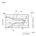
- Fig. 2 illustrates a result obtained by simulating the EGR rate (that is, the amount of EGR / (the amount of EGR + the amount of fresh air)) relative to the opening of the low pressure EGR control valve 42 as illustrated in Fig. 1 under the condition in which the rotational speed and the output torque of the engine are constant.
- the pressure adjustment by the throttle valve 43 in Fig. 1 was not performed.
- the reference numerals 101 and 102 show the EGR rate in the first and second simulations (cases 1 and 2), respectively.
- a region 103 when the low pressure EGR control valve is controlled to a predetermined opening, behavior of the EGR rate in the case 1 is different from behavior of the EGR rate in the case 2, which indicates that there is no reproducibility.
- the reference numeral 104 shows the amount of intake air in the case 1.
- the reference numeral 105 shows the amount of intake air in the case 2. It is found that the EGR rate is different between the cases 1 and 2 according to the difference in the amount of intake air between the cases 1 and 2. This is because a pressure difference between in front of and behind the low pressure EGR control valve 42 fluctuates due to the variations in the amount of intake air. In order to prevent the absence of such reproducibility of the EGR rate, it is desirable to control the pressure difference between in front of and behind the low pressure EGR control valve 42 by the throttle valve 43.
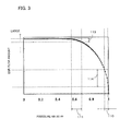
- a pressure P shows the pressure in the downstream of the EGR control valve
- a pressure P0 shows the pressure in the upstream of the EGR control valve.
- the pressure adjustment by the throttle valve 43 as illustrated in Fig. 1 was not performed.
- the low pressure EGR passage 41 is connected to the intake passage 15 whose downstream is close to the atmosphere and to the exhaust passage 16 whose upstream is close to the atmosphere. Therefore, the pressure difference between in front of and behind the low pressure EGR control valve 42 is small.
- the pressure ratio Pr takes a value which is close to nearly 1.
- the pressure ratio Pr of the low pressure EGR control valve 42 exists in a region shown by the reference numeral 110. In the region, as shown by the reference numeral 114, a change in the EGR flow amount relative to a change in the pressure ratio Pr is large.
- the high pressure EGR control valve 32 will be described here for comparison.
- the high pressure EGR passage 31 is connected between the intake manifold 4 and the exhaust manifold 6 coupled to the cylinder of the engine.
- a pressure difference between in front of and behind the high pressure EGR control valve 32 is high.
- the pressure ratio Pr takes a value near about 0.6 and exists in a region shown by the reference numeral 111. In the region, as shown by the reference numeral 113, a change in the EGR flow amount relative to a change in the pressure ratio Pr is small. In summary, a change in the EGR flow amount relative to a change in the pressure difference between in front of and behind the low pressure EGR control valve 42 is large.
- a region in which a change in the EGR flow amount relative to a pressure change is small is selected.
- Fig. 4(a) illustrates an example of a result obtained by simulating a change in the EGR flow amount relative to a pressure differences ⁇ p between in front of and behind the low pressure EGR control valve 42.
- the "change in the EGR flow amount" is calculated by (the EGR flow amount when the pressure P[kPa] in the downstream of the low pressure EGR control valve 42 is increased to (P+1)[kPa] / the EGR flow amount when the pressure in the downstream of the low pressure EGR control valve 42 is P[kPa]).
- the "change in the EGR flow amount” represents how much the EGR flow amount is changed relative to the pressure difference ⁇ p when the pressure P in the downstream of the low pressure EGR control valve 42 is increased by 1[kPa] due to, for example, variations in the amount of intake air.
- a change in the EGR flow amount relative to a pressure change is large as shown by the reference numeral 121.
- a change in the EGR flow amount relative to a pressure change is less than 10% as shown by the reference numeral 123. Therefore, when the pressure difference between in front of and behind the low pressure EGR control valve 42 falls within the pressure difference region 122 having about 6 kPa or more by the throttle valve 43, variations in the EGR flow amount can be greatly reduced. For example, when the pressure difference ⁇ p is 10 kPa, a change in the EGR flow amount is about 5%.
- the throttle valve 43 is controlled so as to form a pressure difference falling within the region 122 between in front of and behind the low pressure EGR control valve 42. Large variations in the EGR flow amount due to a pressure change can be thus prevented.
- the throttle valve 43 is controlled so as to reduce the pumping loss of the throttle valve 43.
- Fig. 4(b) illustrates a ratio of a pumping work to the net work, relative to the pressure difference ⁇ p between in front of and behind the low pressure EGR control valve 42.
- the engine 2 generates an output (work) by rotating the crankshaft connected to the piston ( Fig. 1 ).
- the pumping work generated when the throttle valve 43 throttles air is a loss (referred to as a so-called "pumping loss") relative to the engine output.
- the net work is obtained by subtracting the loss such as the pumping work and so on, from the output generated by the engine.
- the pumping work of the throttle valve 43 is increased. This is because, as the pressure difference ⁇ p is increased, the work required to operate the throttle valve 43 is increased.
- the pumping work changes depending on the load of the engine. As shown by the reference numeral 125, when the engine is at full load, the ratio of the pumping work is about 1.5% at the pressure difference ⁇ p of about 10 kPa. As shown by the reference numeral 126, when the engine is at half load (which is middle load, and typically shows an averaged load in the normal running), the ratio of the pumping work at the pressure difference ⁇ p of about 10 kPa is about 3%. Preferably, the ratio of the pumping work is lower. For example, it is preferable that the ratio of the pumping work is controlled to about 3% or less.
- the pressure difference region is selected from the region 122 described with reference to Fig. 4(a) so that the ratio of the pumping work illustrated in Fig. 4(b) is reduced.
- a pressure difference region 127 of 6 to 10 kPa is selected.
- an object of the present invention is to control the throttle valve 43 so that the pressure difference between in front of and behind the low pressure EGR control valve falls within a predetermined range.
- the predetermined range is the pressure difference region 122 selected so that a change in the EGR flow amount relative to a pressure change in the downstream of the low pressure EGR control valve is small.
- the predetermined range is the pressure difference region 127 in which the pumping loss of the throttle valve 43 is reduced.
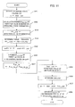
- Fig. 5 is a flowchart of a process for controlling the low pressure EGR control valve 42 via a feedback control of the throttle valve 43. The process is performed at predetermined time intervals by the CPU of the ECU 1.
- step S1 an actual pressure P1 in the downstream of the low pressure EGR control valve 42 is detected as P1 act based on the detection value of the pressure sensor 44 ( Fig. 1 ).
- step S2 a target value P1_cmd of the pressure in the downstream of the low pressure EGR control valve 42 is determined. The target value P1_cmd is set so that a desired pressure difference is generated.
- the target value P1_cmd in the downstream of the low pressure EGR control valve is set to a value (P0 - a desired pressure difference) that is obtained by subtracting the desired pressure difference from the atmospheric pressure P0.
- the upstream pressure of the low pressure EGR control valve 42 is P0, and the downstream pressure becomes (P0 - a desired pressure difference).
- the desired pressure difference is generated between in front of and behind the low pressure EGR control valve 42.
- the atmospheric pressure P0 can be detected from the atmospheric pressure sensor 51 ( Fig. 1 ).
- a second pressure sensor may be provided upstream of the low pressure control valve 42.
- the detection value of the second pressure sensor may be used as P0.
- the desired pressure difference is preferably set so as to fall within the pressure difference region 122 in which a change in the EGR flow amount relative to a pressure change is small.
- the desired pressure difference is set so as to fall within the pressure difference region 127 so as to reduce the pumping loss of the throttle valve 43.
- the desired pressure difference is set to 10 kPa. Accordingly, a change in the EGR flow amount can be reduced to about 5% while the pumping loss can be reduced to about 3%.
- step S3 a difference errP1 between the actual pressure P1_act and the target pressure P1_cmd is calculated.
- step S4 as shown by the following equation, a predetermined PI control is performed so as to cause the difference errP1 to converge to zero to calculate a target opening ⁇ LPL TH of the throttle valve 43.
- KP TH is the P (proportion) term gain
- KI TH is the I (integration) term gain. They are set to values determined via a simulation or the like.
- ⁇ LPL_TH KP TH ⁇ errP ⁇ 1 + KI TH ⁇ ⁇ err ⁇ P ⁇ 1
- the throttle valve 43 is controlled via a control signal to reach the calculated target opening ⁇ PL TH .
- the opening of the throttle valve 43 is controlled so that the desired pressure difference is generated.
- the PI control is used, another control manner may be used to cause the difference errP1 to converge.
- Steps S5 to S8 are a process for controlling the low pressure EGR control valve 42.
- the amount of fresh intake air is detected as Qair_act from the detection value of the air flow sensor 17 ( Fig. 1 ).
- a target value of the amount of fresh intake air is determined based on the operating state of the engine 2. The target value can be determined by referring to a predetermined map (which can be stored in the memory of the ECU 1) based on the detected engine rotational speed NE (which can be detected from an output of the crank angle sensor 52) and the engine load (which can be detected from the intake manifold pressure sensor 21).
- step S7 a difference err between the actual value Qair_act of the amount of fresh intake air and the target value Qair_cmd is calculated.
- step S8 as shown by the following equation, a predetermined PI control is performed so as to cause the difference err to converge to zero to calculate an opening ⁇ LPL EGR of the low pressure EGR control valve 42.
- KP EGR is the P (proportion) term gain
- KI EGR is the I (integration) term gain. They are set to values determined via a simulation or the like.
- ⁇ LPL_EGR KP EGR ⁇ err + KI EGR ⁇ ⁇ err
- the low pressure EGR control valve 42 is controlled via a control signal to reach the calculated opening ⁇ LPL FGR .
- the PI control is used, another control manner may be used to cause the difference err to converge.
- the EGR rate of the low pressure EGR control valve 42 can be controlled by controlling the pressure difference between in front of and behind the low pressure EGR control valve 42 via the feedback control of the throttle valve 43. Further, the pressure difference between in front of and behind the low pressure EGR control valve 42 is controlled via the feedback control of the throttle valve 43 so as to fall within the pressure difference region in which a change in the EGR flow amount relative to a change in pressure is small. Therefore, large variations in the EGR flow amount can be prevented. Further, the pressure difference between in front of and behind the low pressure EGR control valve 42 is controlled so as to fall within the pressure difference region in which the pumping loss of the throttle valve 43 is reduced. Therefore, the pumping loss due to the operation of the throttle valve 43 can be reduced.
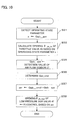
- Fig. 6 is a flowchart of a process for controlling the low pressure EGR control valve 42 via a feedforward control of the throttle valve 43. The process is performed at predetermined time intervals by the CPU of the ECU 1.
- step S11 an operating state parameter showing the amount of intake air or the amount of exhaust gas of the engine is detected as x.
- the detection value Qair_act of the air flow sensor 17 can be used as such an operation state parameter.
- the engine rotational speed NE and the intake manifold pressure PB, the engine rotational speed NE and the output torque, and the engine rotational speed NE and the engine load may be used as the operating state parameters showing the amount of intake air and the amount of exhaust gas, respectively.
- step S12 a predetermined map (which can be stored in the memory of the ECU 1) is referred to based on the operating state parameter x to determine a target opening ⁇ LPL_TH of the throttle valve 43.
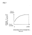
- Fig. 7 illustrates an example of the map.
- the map is set so that as the operating state parameter x (in this example, the amount of intake air Qair_act) is increased, the opening of the throttle valve 43 becomes larger.
- the opening of the throttle valve 43 is constant, the pressure difference between in front of and behind the throttle valve 43 is increased as the amount of intake air Qair_act becomes larger. Therefore, in order to maintain the desired pressure difference, as the amount of intake air Qair_act is increased, the opening of the throttle valve 43 becomes larger.
- the target opening ⁇ LPL_TH of the throttle valve 43 is defined to generate the pressure difference so as to fall within the pressure difference region 122 or 127 described with reference to Figs. 4(a) and 4(b) .
- the opening of the throttle valve 43 for maintaining the pressure difference 10 kPa is determined relative to the amount of intake air and can be defined in the map.
- the map is defined so that the opening of the throttle valve 43 is increased as the amount of the exhaust gas becomes larger.
- the throttle valve 43 is controlled via a control signal to reach the determined target opening ⁇ LPL_TH . Accordingly, the desired pressure difference is generated between in front of and behind the low pressure EGR control valve 42.
- Steps S15 to S18 are a process for controlling the low pressure EGR control valve 42 and are similar to steps S5 to S8 of Fig. 5 , and the description thereof is omitted.
- Fig. 8 is a schematic block diagram of an internal combustion engine (hereinafter referred to as an engine) and its controller according to a second embodiment of the present invention. Only the points different from Fig. 1 will be described.
- the throttle valve 43 is provided downstream of a point where the low pressure EGR passage 41 is connected to the exhaust passage 16.
- the opening of the throttle valve 43 is adjusted to form a predetermined pressure in the upstream of the throttle valve 43.
- a desired pressure difference can be generated between the upstream and downstream of the low pressure EGR control valve 42.
- the throttle valve 43 is connected to an actuator (not illustrated). The opening of the throttle valve 43 is controlled by the actuator according to a control signal from the ECU 1.
- the pressure sensor 44 is provided between the throttle valve 43 and the low pressure EGR control valve 42 to detect the pressure in the upstream of the low pressure EGR control valve 42 (or in the downstream of the throttle valve 43). The detection signal is transmitted to the ECU 1.
- the throttle valve 43 is controlled so that a pressure difference between in front of and behind the low pressure EGR control valve 42 falls within a predetermined range. More preferably, the predetermined range is the pressure difference region 122 in which a change in the EGR flow amount relative to a pressure change in the upstream of the low pressure EGR control valve 42 is small ( Fig. 4(a) ). More preferably, the predetermined range is the pressure difference region 127 in which the pumping loss of the throttle valve 43 is reduced ( Fig. 4(b) ).
- Fig. 9 is a flowchart of a process for controlling the low pressure EGR control valve 42 via a feedback control of the throttle valve 43. The process is performed at predetermined time intervals by the CPU of the ECU 1.
- step S21 an actual pressure P4 in the upstream of the low pressure EGR control valve 42 is detected as P4_act based on the detection value of the pressure sensor 44 ( Fig. 8 ).
- step S22 a target value P4_cmd of the pressure in the upstream of the low pressure EGR control valve 42 is determined. The target value P4_cmd is set so that a desired pressure difference is generated.
- the downstream of the low pressure EGR control valve 42 is connected to the intake passage 15.
- the downstream pressure of the low pressure EGR control valve 42 can be considered to be almost the atmospheric pressure P0. Therefore, the target value P4_cmd of the pressure in the upstream of the low pressure EGR control valve is set to a value (P0 + a desired pressure difference) that is obtained by adding the desired pressure difference to the atmospheric pressure P0. In doing so, the downstream pressure of the low pressure EGR control valve 42 is P0, and the upstream pressure becomes (P0 + a desired pressure difference). As a result, the desired pressure difference is generated between in front of and behind the low pressure EGR control valve 42.
- the atmospheric pressure P0 can be detected from the atmospheric pressure sensor 51 ( Fig. 8 ).
- a second pressure sensor may be provided downstream of the low pressure control valve 42.
- the detection value of the second pressure sensor may be used as P0.
- the desired pressure difference is set so as to fall within the pressure difference region 122 in which a change in the EGR flow amount relative to a pressure change is small.
- the desired pressure difference is set so as to fall within the pressure difference region 127 so as to reduce the pumping loss of the throttle valve 43.
- the desired pressure difference is set to 10 kPa. Accordingly, a change in the EGR flow amount can be reduced to about 5% while the pumping loss can be reduced to about 3%.
- step S23 a difference errP4 between the actual pressure P4_act and the target pressure P4_cmd is calculated.
- step S24 as shown by the following equation, a predetermined PI control is performed so as to cause the difference errP4 to converge to zero to calculate a target opening ⁇ LPL_TH of the throttle valve 43.
- KP TH is the P (proportion) term gain
- KI TH is the I (integration) term gain. They are set to values determined via a simulation or the like.
- ⁇ LPL_TH KP TH ⁇ errP ⁇ 1 + KI TH ⁇ ⁇ err ⁇ P ⁇ 1
- the throttle valve 43 is controlled via a control signal to reach the calculated target opening ⁇ LPL_TH .
- the opening of the throttle valve 43 is controlled so that the desired pressure difference is generated.
- the PI control is used, another control manner may be used for causing the difference errP4 to converge.
- Steps S25 to S28 are a process for controlling the low pressure EGR control valve 42 and are similar to steps S5 to S8 of Fig. 5 , and the description thereof is omitted.
- Fig. 10 is a flowchart of a process for controlling the low pressure EGR control valve 42 via a feedfoward control of the throttle valve 43. The process is performed at predetermined time intervals by the CPU of the ECU 1.
- step S31 an operating state parameter showing the amount of intake air or the amount of exhaust gas of the engine is detected as x.
- the detection value Qair_act of the air flow sensor 17 can be used as such an operateing state parameter.
- the engine rotational speed NE and the intake manifold pressure PB, the engine rotational speed NE and the output torque, and the engine rotational speed NE and the engine load may be used as the operating state parameters showing the amount of intake air and the amount of exhaust gas, respectively.
- a predetermined map (which can be stored in the memory of the ECU 1) is referred to based on the operating state parameter x to determine a target opening ⁇ LPL_TH of the throttle valve 43.
- the predetermined map is the same as that illustrated in Fig. 7 . The description with reference to Fig. 7 holds true. Specifically, in the map, as the amount of intake air Qair_act is increased, the target opening of the throttle valve 43 becomes larger. In the map, the target opening ⁇ LPL_TH of the throttle valve is defined so that the pressure difference that falls within the pressure difference region 122 or 127 described with reference to Figs. 4(a) and 4(b) is generated. When the amount of exhaust gas is used as the operating state parameter, a similar map is defined.
- the throttle valve 43 is controlled via a control signal to reach the determined target opening ⁇ LPL_TH .
- the desired pressure difference is generated between in front of and behind the low pressure EGR control valve 42.
- Steps S35 to S38 are a process for controlling the low pressure EGR control valve 42 and are similar to steps S25 to S28 of Fig. 9 , and the description thereof is omitted.
- Fig. 11 is a flowchart of a process for controlling the opening of the throttle valve 43 using both a feedforward control and a feedback control to control the low pressure EGR control valve 42 via these controls, according to the first embodiment illustrated in Fig. 1 .
- the process is performed at predetermined time intervals by the CPU of the ECU 1.
- the opening of the throttle valve 43 can be corrected by a feedforward control so as to reduce the influence due to a change (disturbance) in the operating state parameter x, while the opening of the throttle valve 43 can converge to a target opening robustly relative to such disturbance by a feedback control. Therefore, the control accuracy of the throttle valve 43 can be improved.
- Steps S41 and S42 are a process for calculating a feedforward term and are similar to steps S11 and S12 of Fig. 6 .
- an operating state parameter in this example, the amount of intake air Qair_act detected by the air flow sensor 17
- the map as illustrated in Fig. 7 is referred to based on the amount of intake air Qair_act.
- the opening ⁇ LPL_TH of the throttle valve 43 is calculated as a feedforward term ⁇ LPL_TH_ff .
- Steps S43 to S46 are a process for calculating a feedback term and are similar to steps S1 to S4 of Fig. 5 .
- the PI control is performed so as to cause the difference errP1 between the detection value P1_act and the target value P1_cmd of the pressure sensor 44 to converge to zero.
- the opening ⁇ LPL_TH of the throttle valve 43 is calculated as a feedback term ⁇ LPL_TH_fb .
- step S47 the feedforward term and the feedback term are added to calculate a target opening ⁇ LPL_TH of the throttle valve 43.
- the throttle valve 43 is controlled via a control signal to reach the calculated target opening ⁇ LPL_TH .
- the opening of the throttle valve 43 is controlled so that a desired pressure difference is generated.
- the PI control is used, another control manner may be used for causing the difference errP1 to converge.
- Steps S55 to S58 are similar to steps S5 to S8 of Fig. 5 , and the description thereof is omitted.
- the amount of air taken into the engine 2 is controlled by the throttle valve 20.
- the amount of air taken into the engine 2 may be controlled by the amount of lift of the intake valve 3.
- the present invention is applicable to a form which the supercharger 10 is not provided.
- the intake side of the low pressure EGR passage 41 is connected upstream from a point where the high pressure EGR passage 31 is connected to the intake manifold.
- the exhaust side of the low pressure EGR passage 41 is connected downstream of the exhaust gas purification means (in the above embodiments, the DPF 22 or the catalytic device 23).
Landscapes
- Engineering & Computer Science (AREA)
- Chemical & Material Sciences (AREA)
- Combustion & Propulsion (AREA)
- Mechanical Engineering (AREA)
- General Engineering & Computer Science (AREA)
- Physics & Mathematics (AREA)
- Fluid Mechanics (AREA)
- Analytical Chemistry (AREA)
- Exhaust-Gas Circulating Devices (AREA)
- Output Control And Ontrol Of Special Type Engine (AREA)
- Electrical Control Of Air Or Fuel Supplied To Internal-Combustion Engine (AREA)
- Control Of Throttle Valves Provided In The Intake System Or In The Exhaust System (AREA)
Abstract
Description
- The present invention relates to an EGR controller for an internal combustion engine.
- There has been proposed an EGR device (high pressure EGR device) which returns part of exhaust gas to an intake side in an internal combustion engine and then performs combustion with the returned exhaust gas (EGR gas) to lower a combustion temperature, thereby reducing the amount of generated NOx (nitride oxide). As in Japanese Patent Application Laid-Open No.
2005-127247 2004-150319 - Japanese Patent Application Laid-Open No.
2002-21625 - The amount of EGR gas recirculated by the low pressure EGR device is changed according to a pressure difference in front of and behind (upstream and downstream of) the EGR control valve which is provided in a passage through which the EGR gas passes for controlling the amount of EGR gas. It is desirable to control the pressure difference in order to recirculate a desired amount of EGR gas.
- In the conventional art as described above, the back pressure valve is provided downstream from the point where the EGR passage is connected to the exhaust manifold. However, a manner for controlling the back pressure valve is not suggested at all.
- One object of the present invention is to propose a manner for controlling a pressure difference in front of and behind an EGR control valve so as to control the amount of EGR gas recirculated by a low pressure EGR device more accurately.
- According to one aspect of the present invention, an EGR controller for an internal combustion engine comprises an exhaust gas purification means (22) provided in an exhaust passage of the internal combustion engine; a low pressure EGR passage (41) for recirculating exhaust gas from the exhaust passage downstream of the exhaust gas purification means to an intake passage of the internal combustion engine; a low pressure EGR control valve (42) provided in the low pressure EGR passage and controlling an amount of the recirculated exhaust gas; a throttle valve (43) provided in the exhaust passage connected to the low pressure EGR passage or the intake passage connected to the low pressure EGR passage; pressure detection means (44) for detecting a pressure between the throttle valve and the low pressure EGR control valve; and controlling means (1) for controlling the throttle valve based on the detected pressure so that a pressure difference within a predetermined range is formed between the upstream and downstream of the low pressure EGR control valve.
- According to the present invention, the throttle valve is controlled (feedback control) based on the detected pressure so that a pressure difference within the predetermined range is formed between in front of and behind the low pressure EGR control valve. Because a desired pressure difference can be formed between in front of and behind the low pressure EGR control valve, a desired amount of exhaust gas can be stably recirculated.
- According to one embodiment of the present invention, when the throttle valve is provided in the intake passage (
Fig. 1 ), the pressure detection means (44) detects a pressure (P1) in the downstream of the low pressure EGR control valve. The controlling means controls the throttle valve so that a pressure difference of the downstream pressure relative to a pressure (P0) in the upstream of the low pressure EGR control valve is formed to be a predetermined value or less. When the throttle valve is provided in the exhaust passage (Fig. 8 ), the pressure detection means (44) detects a pressure (P4) in the upstream of the low pressure EGR control valve. The controlling means controls the throttle valve so that a pressure difference of the upstream pressure relative to the pressure (P0) in the downstream of the low pressure EGR control valve is formed to be a predetermined value or more. Thus, in either of the form of providing the throttle valve on the intake side and the form of providing the throttle valve on the exhaust side, a desired pressure difference is formed between in front of and behind the low pressure EGR control valve. - According to another aspect of the present invention, an EGR controller for an internal combustion engine has an exhaust gas purification means provided in an exhaust passage of the internal combustion engine; a low pressure EGR passage (41) for recirculating exhaust gas from the exhaust passage downstream of the exhaust gas purification means to an intake passage of the internal combustion engine; a low pressure EGR control valve (42) provided in the low pressure EGR passage and controlling an amount of the recirculated exhaust gas; a throttle valve (43) provided in the exhaust passage connected to the low pressure EGR passage or the intake passage connected to the low pressure EGR passage; and a controlling means (1) for controlling the throttle valve based on a value of an operating state parameter showing a current amount of intake air or a current amount of exhaust gas so that a pressure difference within a predetermined range is formed between the upstream and downstream of the low pressure EGR control valve.
- According to the present invention, the throttle valve is controlled (feedforward control) based on the value of the operating state parameter showing the current amount of intake air or the current amount of exhaust gas so as to form a pressure difference within the predetermined range between in front of and behind the low pressure EGR control valve. Because a desired pressure difference can be formed between in front of and behind the low pressure EGR control valve, a desired amount of exhaust gas can be recirculated.
- According to one embodiment of the present invention, the throttle valve is controlled so that as the value of the operating state parameter is increased, the opening of the throttle valve becomes larger. Thus, even if the amount of intake air or the amount of exhaust gas varies, a desired pressure difference can be formed between in front of and behind the low pressure EGR control valve.
- According to one embodiment of the present invention, the predetermined range is set within a pressure difference region (122) in which a change in the amount of exhaust gas recircualated via the low pressure EGR control valve relative to a pressure change in either one, having the throttle valve, of the upstream side and the downstream side of the low pressure EGR control valve, is small.
- According to the present invention, the predetermined range is set within a pressure difference region in which a change in the amount of EGR flow relative to a pressure change is small. Thus, an abrupt change in the amount of EGR flow can be prevented. A desired amount of EGR flow can be maintained by the controlling means.
- According to one embodiment of the present invention, the predetermined range is set within a pressure difference region (127) in which a pumping loss of the throttle valve has a predetermined value or less.
- According to the present invention, the predetermined range is set within the pressure difference region so as to reduce the pumping loss. Thus, an increase of the pumping loss due to the operation of the throttle valve can be prevented.
-
-
Fig. 1 is a diagram schematically illustrating an internal combustion engine having a low pressure EGR device and a high pressure EGR device and its controller according to a first embodiment of the present invention. -
Fig. 2 is a diagram for explaining a problem of reproducibility of an EGR rate of a low pressure EGR device. -
Fig. 3 is a diagram illustrating a change in an amount of EGR flow relative to a pressure ratio between in front of and behind an EGR control valve according to an embodiment of the present invention. -
Fig. 4(a) is a diagram illustrating a change in an amount of EGR flow relative to a pressure difference, andFig. 4(b) is a diagram illustrating a ratio of a pumping work relative to a pressure difference according to an embodiment of the present invention. -
Fig. 5 is a flowchart of a process for controlling a low pressure EGR control valve via a feedback control of a throttle valve according to the first embodiment of the present invention. -
Fig. 6 is a flowchart of a process for controlling a low pressure EGR control valve via a feedforward control of a throttle valve according to the first embodiment of the present invention. -
Fig. 7 is a map illustrating a target opening of a throttle valve based on an operating state parameter according to the first embodiment of the present invention. -
Fig. 8 is a diagram schematically illustrating an internal combustion engine having a low pressure EGR device and a high pressure EGR device and its controller according to a second embodiment of the present invention. -
Fig. 9 is a flowchart of a process for controlling a low pressure EGR control valve via a feedback control of a throttle valve according to the second embodiment of the present invention. -
Fig. 10 is a flowchart of a process for controlling a low pressure EGR control valve via a feedforward control of a throttle valve according to the second embodiment of the present invention. -
Fig. 11 is a flowchart of a process for controlling a low pressure EGR control valve via a feedback control and a feedforward control of a throttle valve according to the first embodiment of the present invention. - Embodiments of the present invention will be described with reference to the drawings.
-
Fig. 1 is a schematic block diagram of an internal combustion engine (hereinafter referred to as an engine) and its controller according to a first embodiment of the present invention. - An electronic control unit (hereinafter referred to as an "ECU") 1 is a computer having a central processing unit (CPU) and a memory. The memory can store one or more computer programs for implementing various controls of a vehicle and data (including one or more maps) used for executing the programs. The
ECU 1 receives and computes data transmitted from each part of the vehicle and generates one or more control signals for controlling each part of the vehicle. - In this embodiment, the
engine 2 is a diesel engine. Theengine 2, for example, has four cylinders and only one of them is illustrated in the drawing. - The
engine 2 is coupled to anintake manifold 4 via an intake valve 3 and is coupled to anexhaust manifold 6 via anexhaust valve 5. Afuel injection valve 7 is attached so as to face acombustion chamber 9 formed above apiston 8. Thefuel injection valve 7 is connected to a high pressure pump and a fuel tank (not illustrated) via a common-rail (not illustrated). The high pressure pump raises the pressure of fuel in the fuel tank and feeds the fuel to thefuel injection valve 7 via the common-rail. Thefuel injection valve 7 injects the received fuel into thecombustion chamber 9. The injection duration and the injector timing of thefuel injection valve 7 are controlled according to a control signal from theECU 1. - A
supercharger 10 is provided. Thesupercharger 10 has arotatable compressor 11 provided in anintake passage 15 communicating with theintake manifold 4, arotatable turbine 12 provided in anexhaust passage 16 communicating with theexhaust manifold 6, and ashaft 13 coupling these. Theturbine 12 is rotationally driven by the kinetic energy of exhaust gas. Thecompressor 11 is rotationally driven by the rotational driving of theturbine 12 to compress intake air. - The
turbine 12 has a plurality of rotatable variable vanes (only two are illustrated) 14 and varies the opening of the variable vanes 14 (hereinafter referred to as a vane opening) according to a control signal from theECU 1. The rotational speed of theturbine 12 can be changed by varying the vane opening. As the variable vane opening is made smaller, the rotational speed of the turbine becomes higher, thereby increasing the boost pressure. - An
air flow sensor 17 and anair cleaner 18 are provided in theintake passage 15 upstream of thecompressor 11. A watercooling type intercooler 19 is provided downstream of thecompressor 11. Theair flow sensor 17 detects the amount of air (the amount of intake air) filtered by theair cleaner 18 and introduced into theintake passage 15. The detection signal is transmitted to theECU 1. Theintercooler 19 cools the intake air, for example when the temperature of the intake air is increased by the supercharging operation of thesupercharger 10. - A
throttle valve 20 is provided downstream of theintercooler 19. Thethrottle valve 20 is connected to an actuator. The actuator controls the opening of thethrottle valve 20 according to a control signal from theECU 1. - An intake
manifold pressure sensor 21 for detecting the pressure of theintake manifold 4 is provided downstream of thethrottle valve 20. The detection value is transmitted to theECU 1. - A filter (referred to as a DPF) 22 for collecting solid particulates such as uncombusted HC (hydrocarbon) in the exhaust gas and a catalytic device (referred to as an LNC) 23 adsorbing NOx in the exhaust gas are provided in the
exhaust passage 16 downstream of theturbine 12. The exhaust gas is purified by these devices. Alternatively, as a means for purifying the exhaust gas, another device (such as a catalyst and/or a filter) may be provided. - A high
pressure EGR passage 31 is connected between the intake manifold downstream of thecompressor 11 and thethrottle valve 20, and the exhaust manifold upstream of theturbine 12. Part of the exhaust gas of theengine 2 is recirculated as EGR gas to theintake manifold 4 via the highpressure EGR passage 31. - A high pressure
EGR control valve 32 is provided in the highpressure EGR passage 31. The opening of the high pressureEGR control valve 32 is controlled by a control signal from theECU 1. Therefore, the amount of the EGR gas recirculated to theintake manifold 4 via the highpressure EGR passage 31 can be controlled. AnEGR cooler 33 is provided in the highpressure EGR passage 31. The EGR gas at a high temperature from theexhaust manifold 6 is cooled by theEGR cooler 33 and is then recirculated to theintake manifold 4. - A low
pressure EGR passage 41 is connected between the intake passage upstream of thecompressor 11 and theexhaust passage 16 downstream of theturbine 12 and theDPF 22. Part of the exhaust gas of theengine 2 is recirculated as the EGR gas to theintake passage 15 via the lowpressure EGR passage 41. Alternatively, the exhaust side of the lowpressure EGR passage 41 may be connected downstream of thecatalytic device 23. - A low pressure
EGR control valve 42 is provided in the lowpressure EGR passage 41. The opening of the low pressureEGR control valve 42 is controlled by a control signal from theECU 1. Therefore, the amount of the EGR gas (the amount of EGR) recirculated to theintake passage 15 via the lowpressure EGR passage 41 can be controlled. - Thus, the EGR gas is recirculated, not only via the high
pressure EGR passage 31, but also via the lowpressure EGR passage 41. Therefore, the combustion temperature in thecombustion chamber 9 can be lowered. NOx in the exhaust gas can be reduced. - The low
pressure EGR passage 41 is connected between the intake passage upstream of thethrottle valve 20 and thecompressor 11, and the exhaust passage downstream of theturbine 12 and theDPF 22. Thus, a pressure difference between in front of and behind (upstream and downstream of) the low pressureEGR control valve 42 provided in the lowpressure EGR passage 41 is very small. Therefore, anotherthrottle valve 43 is provided so as to generate a pressure difference therebetween. The recirculation of the EGR gas flowing through the lowpressure EGR passage 41 to theintake passage 15 can be promoted by the pressure difference thus generated. - In the first embodiment, the
throttle valve 43 is provided upstream of a point where the lowpressure EGR passage 41 is connected to theintake passage 15. The opening of thethrottle valve 43 is adjusted to form a predetermined pressure in the downstream of thethrottle valve 43. Accordingly, a desired pressure difference can be generated between the upstream and downstream of the low pressureEGR control valve 42. - The
throttle valve 43 is connected to an actuator (not illustrated). The opening of thethrottle valve 43 is controlled by the actuator according to a control signal from theECU 1. Apressure sensor 44 is provided between thethrottle valve 43 and the low pressureEGR control valve 42. The pressure in the downstream of the low pressure EGR control valve 42 (or in the upstream of the throttle valve 43) is detected. The detection signal is transmitted to theECU 1. - The
ECU 1 is connected to an atmospheric pressure (PA)sensor 51 for detecting the atmospheric pressure. Acrank angle sensor 52 that outputs a crank pulse according to the rotation of a crankshaft (not illustrated) of theengine 2 is connected to theECU 1. TheECU 1 can calculate the rotational speed (NE) of theengine 2 based on the crank pulse. - In response to detection signals from various sensors, the
ECU 1 detects an operating state of theengine 2 and controls a fuel injection amount, a fuel injection timing, the amount of EGR, the amount of intake air, a boost pressure, and so on, according to one or more programs and data (including one or more maps) stored in the memory. - Here, the technical significance of the control of the
throttle valve 43 according to the present invention will be described with reference toFigs. 2 to 4 .Fig. 2 illustrates a result obtained by simulating the EGR rate (that is, the amount of EGR / (the amount of EGR + the amount of fresh air)) relative to the opening of the low pressureEGR control valve 42 as illustrated inFig. 1 under the condition in which the rotational speed and the output torque of the engine are constant. The pressure adjustment by thethrottle valve 43 inFig. 1 was not performed. Thereference numerals cases 1 and 2), respectively. As shown by aregion 103, when the low pressure EGR control valve is controlled to a predetermined opening, behavior of the EGR rate in thecase 1 is different from behavior of the EGR rate in thecase 2, which indicates that there is no reproducibility. - Here, the amount of intake air (which can be detected by the
air flow sensor 17 ofFig. 1 ) in these simulations was observed. Thereference numeral 104 shows the amount of intake air in thecase 1. Thereference numeral 105 shows the amount of intake air in thecase 2. It is found that the EGR rate is different between thecases cases EGR control valve 42 fluctuates due to the variations in the amount of intake air. In order to prevent the absence of such reproducibility of the EGR rate, it is desirable to control the pressure difference between in front of and behind the low pressureEGR control valve 42 by thethrottle valve 43. - Referring to
Fig. 3 , the pressure difference between in front of and behind the low pressureEGR control valve 42 will be considered.Fig. 3 illustrates a simulation result of the EGR flow amount relative to a pressure ratio (Pr = P / P0) between in front of and behind a typical EGR control valve. Here, a pressure P shows the pressure in the downstream of the EGR control valve, and a pressure P0 shows the pressure in the upstream of the EGR control valve. The pressure adjustment by thethrottle valve 43 as illustrated inFig. 1 was not performed. - As apparent from
Fig. 1 , the lowpressure EGR passage 41 is connected to theintake passage 15 whose downstream is close to the atmosphere and to theexhaust passage 16 whose upstream is close to the atmosphere. Therefore, the pressure difference between in front of and behind the low pressureEGR control valve 42 is small. The pressure ratio Pr takes a value which is close to nearly 1. The pressure ratio Pr of the low pressureEGR control valve 42 exists in a region shown by thereference numeral 110. In the region, as shown by thereference numeral 114, a change in the EGR flow amount relative to a change in the pressure ratio Pr is large. On the other hand, the high pressureEGR control valve 32 will be described here for comparison. The highpressure EGR passage 31 is connected between theintake manifold 4 and theexhaust manifold 6 coupled to the cylinder of the engine. A pressure difference between in front of and behind the high pressureEGR control valve 32 is high. The pressure ratio Pr takes a value near about 0.6 and exists in a region shown by thereference numeral 111. In the region, as shown by thereference numeral 113, a change in the EGR flow amount relative to a change in the pressure ratio Pr is small. In summary, a change in the EGR flow amount relative to a change in the pressure difference between in front of and behind the low pressureEGR control valve 42 is large. - As described with reference to
Fig. 2 , it is desirable to control the pressure difference of the low pressureEGR control valve 42 by thethrottle valve 43. However, in the region as shown by thereference numeral 110, even if a control by thethrottle valve 43 is performed, it can be difficult to stably implement a desired EGR flow amount. - In one embodiment of the present invention, as a region of the pressure difference to be controlled by the
throttle valve 43, a region in which a change in the EGR flow amount relative to a pressure change is small is selected.Fig. 4(a) illustrates an example of a result obtained by simulating a change in the EGR flow amount relative to a pressure differences Δp between in front of and behind the low pressureEGR control valve 42. Here, the "change in the EGR flow amount" is calculated by (the EGR flow amount when the pressure P[kPa] in the downstream of the low pressureEGR control valve 42 is increased to (P+1)[kPa] / the EGR flow amount when the pressure in the downstream of the low pressureEGR control valve 42 is P[kPa]). That is, the "change in the EGR flow amount" represents how much the EGR flow amount is changed relative to the pressure difference Δp when the pressure P in the downstream of the low pressureEGR control valve 42 is increased by 1[kPa] due to, for example, variations in the amount of intake air. - As apparent from the drawing, in a
region 120 having the pressure difference Δp lower than about 5[kPa], a change in the EGR flow amount relative to a pressure change is large as shown by thereference numeral 121. In aregion 122 having the pressure difference Δp larger than about 6 kPa, a change in the EGR flow amount relative to a pressure change is less than 10% as shown by thereference numeral 123. Therefore, when the pressure difference between in front of and behind the low pressureEGR control valve 42 falls within thepressure difference region 122 having about 6 kPa or more by thethrottle valve 43, variations in the EGR flow amount can be greatly reduced. For example, when the pressure difference Δp is 10 kPa, a change in the EGR flow amount is about 5%. - Thus, in one embodiment of the present invention, the
throttle valve 43 is controlled so as to form a pressure difference falling within theregion 122 between in front of and behind the low pressureEGR control valve 42. Large variations in the EGR flow amount due to a pressure change can be thus prevented. - In a more preferred embodiment, the
throttle valve 43 is controlled so as to reduce the pumping loss of thethrottle valve 43.Fig. 4(b) illustrates a ratio of a pumping work to the net work, relative to the pressure difference Δp between in front of and behind the low pressureEGR control valve 42. Theengine 2 generates an output (work) by rotating the crankshaft connected to the piston (Fig. 1 ). The pumping work generated when thethrottle valve 43 throttles air is a loss (referred to as a so-called "pumping loss") relative to the engine output. The net work is obtained by subtracting the loss such as the pumping work and so on, from the output generated by the engine. - As illustrated in the drawing, as the pressure difference Δp is increased, the pumping work of the
throttle valve 43 is increased. This is because, as the pressure difference Δp is increased, the work required to operate thethrottle valve 43 is increased. The pumping work changes depending on the load of the engine. As shown by the reference numeral 125, when the engine is at full load, the ratio of the pumping work is about 1.5% at the pressure difference Δp of about 10 kPa. As shown by thereference numeral 126, when the engine is at half load (which is middle load, and typically shows an averaged load in the normal running), the ratio of the pumping work at the pressure difference Δp of about 10 kPa is about 3%. Preferably, the ratio of the pumping work is lower. For example, it is preferable that the ratio of the pumping work is controlled to about 3% or less. - Preferably, the pressure difference region is selected from the
region 122 described with reference toFig. 4(a) so that the ratio of the pumping work illustrated inFig. 4(b) is reduced. By way of example, apressure difference region 127 of 6 to 10 kPa is selected. When the pressure difference of the low pressureEGR control valve 42 is controlled by thethrottle valve 43 so as to fall within theregion 127, the pumping work can be reduced without largely varying the EGR flow amount. - As described above, an object of the present invention is to control the
throttle valve 43 so that the pressure difference between in front of and behind the low pressure EGR control valve falls within a predetermined range. More preferably, the predetermined range is thepressure difference region 122 selected so that a change in the EGR flow amount relative to a pressure change in the downstream of the low pressure EGR control valve is small. More preferably, the predetermined range is thepressure difference region 127 in which the pumping loss of thethrottle valve 43 is reduced. - A specific manner for forming a desired pressure difference between in front of and behind the low pressure
EGR control valve 42 via a control of thethrottle valve 43 will be described below. - A manner for controlling the
throttle valve 43 and the low pressureEGR control valve 42 according to the first embodiment in which thethrottle valve 43 is provided on the intake side, as illustrated inFig. 1 , will be described. -
Fig. 5 is a flowchart of a process for controlling the low pressureEGR control valve 42 via a feedback control of thethrottle valve 43. The process is performed at predetermined time intervals by the CPU of theECU 1. - In step S1, an actual pressure P1 in the downstream of the low pressure
EGR control valve 42 is detected as P1 act based on the detection value of the pressure sensor 44 (Fig. 1 ). In step S2, a target value P1_cmd of the pressure in the downstream of the low pressureEGR control valve 42 is determined. The target value P1_cmd is set so that a desired pressure difference is generated. - Because the upstream of the low pressure
EGR control valve 42 is connected to theexhaust passage 16, the upstream pressure of the low pressureEGR control valve 42 can be considered to be almost the atmospheric pressure. Therefore, the target value P1_cmd in the downstream of the low pressure EGR control valve is set to a value (P0 - a desired pressure difference) that is obtained by subtracting the desired pressure difference from the atmospheric pressure P0. In doing so, the upstream pressure of the low pressureEGR control valve 42 is P0, and the downstream pressure becomes (P0 - a desired pressure difference). As a result, the desired pressure difference is generated between in front of and behind the low pressureEGR control valve 42. Here, the atmospheric pressure P0 can be detected from the atmospheric pressure sensor 51 (Fig. 1 ). - Alternatively, a second pressure sensor may be provided upstream of the low
pressure control valve 42. The detection value of the second pressure sensor may be used as P0. - As described with reference to
Fig. 4(a) , the desired pressure difference is preferably set so as to fall within thepressure difference region 122 in which a change in the EGR flow amount relative to a pressure change is small. As described with reference toFig. 4(b) , more preferably, the desired pressure difference is set so as to fall within thepressure difference region 127 so as to reduce the pumping loss of thethrottle valve 43. In this example, the desired pressure difference is set to 10 kPa. Accordingly, a change in the EGR flow amount can be reduced to about 5% while the pumping loss can be reduced to about 3%. - In step S3, a difference errP1 between the actual pressure P1_act and the target pressure P1_cmd is calculated. In step S4, as shown by the following equation, a predetermined PI control is performed so as to cause the difference errP1 to converge to zero to calculate a target opening θLPL TH of the
throttle valve 43. Here, KPTH is the P (proportion) term gain, and KITH is the I (integration) term gain. They are set to values determined via a simulation or the like.
- The
throttle valve 43 is controlled via a control signal to reach the calculated target opening θPL TH. Thus, the opening of thethrottle valve 43 is controlled so that the desired pressure difference is generated. In this example, although the PI control is used, another control manner may be used to cause the difference errP1 to converge. - Steps S5 to S8 are a process for controlling the low pressure
EGR control valve 42. In step S5, the amount of fresh intake air is detected as Qair_act from the detection value of the air flow sensor 17 (Fig. 1 ). In step S6, a target value of the amount of fresh intake air is determined based on the operating state of theengine 2. The target value can be determined by referring to a predetermined map (which can be stored in the memory of the ECU 1) based on the detected engine rotational speed NE (which can be detected from an output of the crank angle sensor 52) and the engine load (which can be detected from the intake manifold pressure sensor 21). - In step S7, a difference err between the actual value Qair_act of the amount of fresh intake air and the target value Qair_cmd is calculated. In step S8, as shown by the following equation, a predetermined PI control is performed so as to cause the difference err to converge to zero to calculate an opening θ LPL EGR of the low pressure
EGR control valve 42. Here, KPEGR is the P (proportion) term gain, and KIEGR is the I (integration) term gain. They are set to values determined via a simulation or the like.
- Accordingly, the low pressure
EGR control valve 42 is controlled via a control signal to reach the calculated opening θLPL FGR. In this example, although the PI control is used, another control manner may be used to cause the difference err to converge. - Thus, the EGR rate of the low pressure
EGR control valve 42 can be controlled by controlling the pressure difference between in front of and behind the low pressureEGR control valve 42 via the feedback control of thethrottle valve 43. Further, the pressure difference between in front of and behind the low pressureEGR control valve 42 is controlled via the feedback control of thethrottle valve 43 so as to fall within the pressure difference region in which a change in the EGR flow amount relative to a change in pressure is small. Therefore, large variations in the EGR flow amount can be prevented. Further, the pressure difference between in front of and behind the low pressureEGR control valve 42 is controlled so as to fall within the pressure difference region in which the pumping loss of thethrottle valve 43 is reduced. Therefore, the pumping loss due to the operation of thethrottle valve 43 can be reduced. -
Fig. 6 is a flowchart of a process for controlling the low pressureEGR control valve 42 via a feedforward control of thethrottle valve 43. The process is performed at predetermined time intervals by the CPU of theECU 1. - In step S11, an operating state parameter showing the amount of intake air or the amount of exhaust gas of the engine is detected as x. For example, the detection value Qair_act of the air flow sensor 17 (
Fig. 1 ) can be used as such an operation state parameter. Alternatively, the engine rotational speed NE and the intake manifold pressure PB, the engine rotational speed NE and the output torque, and the engine rotational speed NE and the engine load may be used as the operating state parameters showing the amount of intake air and the amount of exhaust gas, respectively. - In step S12, a predetermined map (which can be stored in the memory of the ECU 1) is referred to based on the operating state parameter x to determine a target opening θLPL_TH of the
throttle valve 43. -
Fig. 7 illustrates an example of the map. The map is set so that as the operating state parameter x (in this example, the amount of intake air Qair_act) is increased, the opening of thethrottle valve 43 becomes larger. When the opening of thethrottle valve 43 is constant, the pressure difference between in front of and behind thethrottle valve 43 is increased as the amount of intake air Qair_act becomes larger. Therefore, in order to maintain the desired pressure difference, as the amount of intake air Qair_act is increased, the opening of thethrottle valve 43 becomes larger. - Preferably, in the map, the target opening θLPL_TH of the
throttle valve 43 is defined to generate the pressure difference so as to fall within thepressure difference region Figs. 4(a) and 4(b) . For example, via a simulation or the like, the opening of thethrottle valve 43 for maintaining thepressure difference 10 kPa is determined relative to the amount of intake air and can be defined in the map. - When the amount of exhaust gas is used as the operating state parameter, a similar map is defined. As the amount of intake air is increased, the amount of exhaust gas becomes larger. Therefore, the map is defined so that the opening of the
throttle valve 43 is increased as the amount of the exhaust gas becomes larger. - The
throttle valve 43 is controlled via a control signal to reach the determined target opening θLPL_TH. Accordingly, the desired pressure difference is generated between in front of and behind the low pressureEGR control valve 42. - Steps S15 to S18 are a process for controlling the low pressure
EGR control valve 42 and are similar to steps S5 to S8 ofFig. 5 , and the description thereof is omitted. -
Fig. 8 is a schematic block diagram of an internal combustion engine (hereinafter referred to as an engine) and its controller according to a second embodiment of the present invention. Only the points different fromFig. 1 will be described. - In the second embodiment, the
throttle valve 43 is provided downstream of a point where the lowpressure EGR passage 41 is connected to theexhaust passage 16. The opening of thethrottle valve 43 is adjusted to form a predetermined pressure in the upstream of thethrottle valve 43. Thus, a desired pressure difference can be generated between the upstream and downstream of the low pressureEGR control valve 42. - The
throttle valve 43 is connected to an actuator (not illustrated). The opening of thethrottle valve 43 is controlled by the actuator according to a control signal from theECU 1. Thepressure sensor 44 is provided between thethrottle valve 43 and the low pressureEGR control valve 42 to detect the pressure in the upstream of the low pressure EGR control valve 42 (or in the downstream of the throttle valve 43). The detection signal is transmitted to theECU 1. - The description with reference to
Figs. 4(a) and 4(b) is basically applied to the second embodiment. Specifically, thethrottle valve 43 is controlled so that a pressure difference between in front of and behind the low pressureEGR control valve 42 falls within a predetermined range. More preferably, the predetermined range is thepressure difference region 122 in which a change in the EGR flow amount relative to a pressure change in the upstream of the low pressureEGR control valve 42 is small (Fig. 4(a) ). More preferably, the predetermined range is thepressure difference region 127 in which the pumping loss of thethrottle valve 43 is reduced (Fig. 4(b) ). - A manner for controlling the
throttle valve 43 and the low pressureEGR control valve 42 according to the second embodiment in which thethrottle valve 43 is provided on the exhaust side, as illustrated inFig. 8 , will be described. -
Fig. 9 is a flowchart of a process for controlling the low pressureEGR control valve 42 via a feedback control of thethrottle valve 43. The process is performed at predetermined time intervals by the CPU of theECU 1. - In step S21, an actual pressure P4 in the upstream of the low pressure
EGR control valve 42 is detected as P4_act based on the detection value of the pressure sensor 44 (Fig. 8 ). In step S22, a target value P4_cmd of the pressure in the upstream of the low pressureEGR control valve 42 is determined. The target value P4_cmd is set so that a desired pressure difference is generated. - The downstream of the low pressure
EGR control valve 42 is connected to theintake passage 15. The downstream pressure of the low pressureEGR control valve 42 can be considered to be almost the atmospheric pressure P0. Therefore, the target value P4_cmd of the pressure in the upstream of the low pressure EGR control valve is set to a value (P0 + a desired pressure difference) that is obtained by adding the desired pressure difference to the atmospheric pressure P0. In doing so, the downstream pressure of the low pressureEGR control valve 42 is P0, and the upstream pressure becomes (P0 + a desired pressure difference). As a result, the desired pressure difference is generated between in front of and behind the low pressureEGR control valve 42. Here, the atmospheric pressure P0 can be detected from the atmospheric pressure sensor 51 (Fig. 8 ). - Alternatively, a second pressure sensor may be provided downstream of the low
pressure control valve 42. The detection value of the second pressure sensor may be used as P0. - As described with reference to
Fig. 4(a) , preferably, the desired pressure difference is set so as to fall within thepressure difference region 122 in which a change in the EGR flow amount relative to a pressure change is small. As described with reference toFig. 4(b) , more preferably, the desired pressure difference is set so as to fall within thepressure difference region 127 so as to reduce the pumping loss of thethrottle valve 43. In this example, the desired pressure difference is set to 10 kPa. Accordingly, a change in the EGR flow amount can be reduced to about 5% while the pumping loss can be reduced to about 3%. - In step S23, a difference errP4 between the actual pressure P4_act and the target pressure P4_cmd is calculated. In step S24, as shown by the following equation, a predetermined PI control is performed so as to cause the difference errP4 to converge to zero to calculate a target opening θLPL_TH of the
throttle valve 43. Here, KPTH is the P (proportion) term gain, and KITH is the I (integration) term gain. They are set to values determined via a simulation or the like.
- The
throttle valve 43 is controlled via a control signal to reach the calculated target opening θLPL_TH. Thus, the opening of thethrottle valve 43 is controlled so that the desired pressure difference is generated. In this example, although the PI control is used, another control manner may be used for causing the difference errP4 to converge. - Steps S25 to S28 are a process for controlling the low pressure
EGR control valve 42 and are similar to steps S5 to S8 ofFig. 5 , and the description thereof is omitted. -
Fig. 10 is a flowchart of a process for controlling the low pressureEGR control valve 42 via a feedfoward control of thethrottle valve 43. The process is performed at predetermined time intervals by the CPU of theECU 1. - In step S31, an operating state parameter showing the amount of intake air or the amount of exhaust gas of the engine is detected as x. For example, the detection value Qair_act of the air flow sensor 17 (
Fig. 8 ) can be used as such an operateing state parameter. Alternatively, the engine rotational speed NE and the intake manifold pressure PB, the engine rotational speed NE and the output torque, and the engine rotational speed NE and the engine load may be used as the operating state parameters showing the amount of intake air and the amount of exhaust gas, respectively. - In step S32, a predetermined map (which can be stored in the memory of the ECU 1) is referred to based on the operating state parameter x to determine a target opening θLPL_TH of the
throttle valve 43. The predetermined map is the same as that illustrated inFig. 7 . The description with reference toFig. 7 holds true. Specifically, in the map, as the amount of intake air Qair_act is increased, the target opening of thethrottle valve 43 becomes larger. In the map, the target opening θLPL_TH of the throttle valve is defined so that the pressure difference that falls within thepressure difference region Figs. 4(a) and 4(b) is generated. When the amount of exhaust gas is used as the operating state parameter, a similar map is defined. - The
throttle valve 43 is controlled via a control signal to reach the determined target opening θLPL_TH. Thus, the desired pressure difference is generated between in front of and behind the low pressureEGR control valve 42. - Steps S35 to S38 are a process for controlling the low pressure
EGR control valve 42 and are similar to steps S25 to S28 ofFig. 9 , and the description thereof is omitted. -
Fig. 11 is a flowchart of a process for controlling the opening of thethrottle valve 43 using both a feedforward control and a feedback control to control the low pressureEGR control valve 42 via these controls, according to the first embodiment illustrated inFig. 1 . The process is performed at predetermined time intervals by the CPU of theECU 1. When both the controls are used, the opening of thethrottle valve 43 can be corrected by a feedforward control so as to reduce the influence due to a change (disturbance) in the operating state parameter x, while the opening of thethrottle valve 43 can converge to a target opening robustly relative to such disturbance by a feedback control. Therefore, the control accuracy of thethrottle valve 43 can be improved. - Steps S41 and S42 are a process for calculating a feedforward term and are similar to steps S11 and S12 of
Fig. 6 . Specifically, an operating state parameter (in this example, the amount of intake air Qair_act detected by the air flow sensor 17) based on the amount of intake air or the amount of exhaust gas is detected as x. The map as illustrated inFig. 7 is referred to based on the amount of intake air Qair_act. The opening θLPL_TH of thethrottle valve 43 is calculated as a feedforward term θLPL_TH_ff. - Steps S43 to S46 are a process for calculating a feedback term and are similar to steps S1 to S4 of
Fig. 5 . The PI control is performed so as to cause the difference errP1 between the detection value P1_act and the target value P1_cmd of thepressure sensor 44 to converge to zero. The opening θLPL_TH of thethrottle valve 43 is calculated as a feedback term θLPL_TH_fb. In step S47, the feedforward term and the feedback term are added to calculate a target opening θLPL_TH of thethrottle valve 43. - The
throttle valve 43 is controlled via a control signal to reach the calculated target opening θLPL_TH. Thus, the opening of thethrottle valve 43 is controlled so that a desired pressure difference is generated. In this example, although the PI control is used, another control manner may be used for causing the difference errP1 to converge. - Steps S55 to S58 are similar to steps S5 to S8 of
Fig. 5 , and the description thereof is omitted. - The use of the feedforward control and the feedback control together is applicable to the second embodiment (
Fig. 8 ) provided with thethrottle valve 43 on the exhaust side. - The above embodiments have been described by taking the diesel engine as an example. The present invention is applicable to other engines (for instance, a typical gasoline engine).
- In the above embodiments, the amount of air taken into the
engine 2 is controlled by thethrottle valve 20. Alternatively, in place of thethrottle valve 20, the amount of air taken into theengine 2 may be controlled by the amount of lift of the intake valve 3. Further, the present invention is applicable to a form which thesupercharger 10 is not provided. When thethrottle valve 20 and thesupercharger 10 are not provided, the intake side of the lowpressure EGR passage 41 is connected upstream from a point where the highpressure EGR passage 31 is connected to the intake manifold. The exhaust side of the lowpressure EGR passage 41 is connected downstream of the exhaust gas purification means (in the above embodiments, theDPF 22 or the catalytic device 23). - The above embodiments are applicable to an internal combustion engine for general purpose use (such as an outboard engine).
Claims (12)
- An EGR controller for an internal combustion engine, comprising:an exhaust gas purification means provided in an exhaust passage of the internal combustion engine;a low pressure EGR passage for recirculating exhaust gas from the exhaust passage downstream of the exhaust gas purification means to an intake passage of the internal combustion engine;a low pressure EGR control valve provided in the low pressure EGR passage and controlling an amount of the recirculated exhaust gas;a throttle valve provided in the exhaust passage connected to the low pressure EGR passage or the intake passage connected to the low pressure EGR passage;a pressure detection means for detecting a pressure between the throttle valve and the low pressure EGR control valve; anda controlling means for controlling the throttle valve based on the detected pressure so that a pressure difference in a predetermined range is formed between the upstream and downstream of the low pressure EGR control valve.
- The EGR controller of an internal combustion engine according to claim 1,
wherein when the throttle valve is provided in the intake passage, the pressure detection means detects a pressure in the downstream of the low pressure EGR control valve, and the controlling means controls the throttle valve so that a pressure difference of the downstream pressure relative to a pressure in the upstream of the low pressure EGR control valve is formed to be a predetermined value or less,
wherein when the throttle valve is provided in the exhaust passage, the pressure detection means detects a pressure in the upstream of the low pressure EGR control valve, and the controlling means controls the throttle valve so that a pressure difference of the upstream pressure relative to the pressure in the downstream of the low pressure EGR control valve is formed to be a predetermined value or more. - An EGR controller for an internal combustion engine, comprising:an exhaust gas purification means provided in an exhaust passage of the internal combustion engine;a low pressure EGR passage for recirculating exhaust gas from the exhaust passage downstream of the exhaust gas purification means to an intake passage of the internal combustion engine;a low pressure EGR control valve provided in the low pressure EGR passage and controlling an amount of the recirculated exhaust gas;a throttle valve provided in the exhaust passage connected to the low pressure EGR passage or the intake passage connected to the low pressure EGR passage; anda controlling means for controlling the throttle valve based on a value of an operating state parameter showing a current amount of intake air or a current amount of exhaust gas so that a pressure difference within a predetermined range is formed between the upstream and downstream of the low pressure EGR control valve.
- The EGR controller of an internal combustion engine according to claim 3,
wherein the controlling means controls the throttle valve so that as the value of the operating state parameter is increased, the opening of the throttle valve becomes larger. - The EGR controller of an internal combustion engine according to any one of claims 1 to 4,
wherein the predetermined range is set within a pressure difference region in which a change in the amount of exhaust gas recirculated via the low pressure EGR control valve relative to a pressure change in either one, having the throttle valve, of the upstream side and the downstream side of the low pressure EGR control valve, is small. - The EGR controller of an internal combustion engine according to any one of claims 1 to 5,
wherein the predetermined range is set within a pressure difference region in which a pumping loss of the throttle valve has a predetermined value or less. - A method for controlling EGR for an internal combustion engine, comprising:re-circulating exhaust gas from the downstream of exhaust gas purification means provided in an exhaust passage of the internal combustion engine via a low pressure EGR passage to an intake passage of the internal combustion engine;controlling an amount of the re-circulated exhaust gas by a low pressure EGR control valve provided in the low pressure EGR passage;detecting a pressure between a throttle valve provided in the exhaust passage connected to the low pressure EGR passage or the intake passage connected to the low pressure EGR passage and the low pressure EGR control valve; andcontrolling the throttle valve based on the detected pressure so that a pressure difference within a predetermined range is formed between the upstream and downstream of the low pressure EGR control valve.
- The method according to claim 7,
wherein when the throttle valve is provided in the intake passage, the detecting step detects a pressure in the downstream of the low pressure EGR control valve, and the step of controlling the throttle valve controls the throttle valve so that a pressure difference of the downstream pressure relative to a pressure in the upstream of the low pressure EGR control valve is formed to be a predetermined value or less,
wherein when the throttle valve is provided in the exhaust passage, the detecting step detects a pressure in the upstream of the low pressure EGR control valve, and the step of controlling the throttle valve controls the throttle valve so that a pressure difference of the upstream pressure relative to the pressure in the downstream of the low pressure EGR control valve is formed to be a predetermined value or more. - A method for controlling EGR for an internal combustion engine, comprising:re-circulating exhaust gas from the downstream of exhaust gas purification means provided in an exhaust passage of the internal combustion engine via a low pressure EGR passage to an intake passage of the internal combustion engine;controlling an amount of the re-circulated exhaust gas by a low pressure EGR control valve provided in the low pressure EGR passage; andcontrolling a throttle valve provided in the exhaust passage connected to the low pressure EGR passage or the intake passage connected to the low pressure EGR passage based on a value of an operating state parameter showing a current amount of intake air or a current amount of exhaust gas so that a pressure difference within a predetermined range between the upstream and downstream of the low pressure EGR control valve is formed.
- The method according to claim 9,
wherein the step of controlling the throttle valve controls the throttle valve so that as the value of the operating state parameter is increased, the opening of the throttle valve becomes larger. - The method according to any one of claims 7 to 10,
wherein the predetermined range is set within a pressure difference region in which a change in the amount of exhaust gas re-circulated via the low pressure EGR control valve relative to a pressure change in either one, having the throttle valve, of the upstream side and the downstream side of the low pressure EGR control valve, is small. - The method according to any one of claims 7 to 11,
wherein the predetermined range is set within a pressure difference region in which a pumping loss of the throttle valve has a predetermined value or less.
Applications Claiming Priority (2)
| Application Number | Priority Date | Filing Date | Title |
|---|---|---|---|
| JP2007088707A JP2008248729A (en) | 2007-03-29 | 2007-03-29 | Egr control device for internal combustion engine |
| PCT/JP2008/054669 WO2008120553A1 (en) | 2007-03-29 | 2008-03-13 | Egr controller for internal combustion engine |
Publications (3)
| Publication Number | Publication Date |
|---|---|
| EP2128407A1 true EP2128407A1 (en) | 2009-12-02 |
| EP2128407A4 EP2128407A4 (en) | 2011-05-04 |
| EP2128407B1 EP2128407B1 (en) | 2012-02-22 |
Family
ID=39808136
Family Applications (1)
| Application Number | Title | Priority Date | Filing Date |
|---|---|---|---|
| EP08738657A Not-in-force EP2128407B1 (en) | 2007-03-29 | 2008-03-13 | Egr controller for internal combustion engine |
Country Status (4)
| Country | Link |
|---|---|
| EP (1) | EP2128407B1 (en) |
| JP (1) | JP2008248729A (en) |
| AT (1) | ATE546632T1 (en) |
| WO (1) | WO2008120553A1 (en) |
Cited By (15)
| Publication number | Priority date | Publication date | Assignee | Title |
|---|---|---|---|---|
| WO2012136412A1 (en) * | 2011-04-05 | 2012-10-11 | Robert Bosch Gmbh | Drive system for a motor vehicle |
| US9341127B2 (en) * | 2014-06-06 | 2016-05-17 | Ford Global Technologies, Llc | Multivariable low-pressure exhaust gas recirculation control |
| EP3075991A1 (en) * | 2015-03-31 | 2016-10-05 | Toyota Jidosha Kabushiki Kaisha | Control device for internal combustion engine |
| US20170051684A1 (en) * | 2015-08-21 | 2017-02-23 | Deere & Company | Feed forward exhaust throttle and wastegate control for an engine |
| RU2628471C1 (en) * | 2015-03-31 | 2017-08-17 | Тойота Дзидося Кабусики Кайся | Control unit for internal combustion engine |
| CN108026841A (en) * | 2015-09-18 | 2018-05-11 | 日产自动车株式会社 | The control device of internal combustion engine and the control method of internal combustion engine |
| CN108026840A (en) * | 2015-09-18 | 2018-05-11 | 日产自动车株式会社 | The control device of internal combustion engine and the control method of internal combustion engine |
| US10151263B2 (en) | 2016-11-22 | 2018-12-11 | Aisan Kogyo Kabushiki Kaisha | Intake system |
| US20190195152A1 (en) * | 2016-09-09 | 2019-06-27 | Nissan Motor Co., Ltd. | Control method and control device for internal combustion engine |
| EP3569847A4 (en) * | 2017-01-16 | 2019-12-25 | Nissan Motor Co., Ltd. | Method for controlling internal combustion engine and device for controlling internal combustion engine |
| US10570836B2 (en) | 2017-06-14 | 2020-02-25 | Aisan Kogyo Kabushiki Kaisha | EGR control apparatus for engine with supercharger and control method of EGR device for engine with supercharger |
| US10760508B2 (en) | 2016-02-18 | 2020-09-01 | Toyota Jidosha Kabushiki Kaisha | Control device for internal combustion engine and internal combustion engine |
| US10830164B2 (en) | 2014-11-12 | 2020-11-10 | Deere & Company | Fresh air flow and exhaust gas recirculation control system and method |
| US10883429B2 (en) | 2017-02-01 | 2021-01-05 | Nissan Motor Co., Ltd. | Intake control method and intake control device for internal combustion engine |
| DE102015221841B4 (en) | 2015-07-14 | 2022-06-09 | Hyundai Motor Company | Method of controlling a back pressure valve |
Families Citing this family (14)
| Publication number | Priority date | Publication date | Assignee | Title |
|---|---|---|---|---|
| JP5249889B2 (en) * | 2009-09-24 | 2013-07-31 | 本田技研工業株式会社 | Control device for internal combustion engine |
| DE112010004964T5 (en) * | 2009-12-22 | 2012-11-22 | Borgwarner Inc. | internal combustion engine |
| JP5434670B2 (en) * | 2010-02-26 | 2014-03-05 | 株式会社デンソー | EGR device |
| JP5651979B2 (en) * | 2010-03-30 | 2015-01-14 | いすゞ自動車株式会社 | EGR device |
| JP2011241797A (en) * | 2010-05-21 | 2011-12-01 | Hino Motors Ltd | Engine intake air cooling device |
| JP2012047093A (en) * | 2010-08-26 | 2012-03-08 | Daihatsu Motor Co Ltd | Internal combustion engine |
| JP5621638B2 (en) * | 2011-02-08 | 2014-11-12 | トヨタ自動車株式会社 | Exhaust gas recirculation system for internal combustion engines |
| JP5598376B2 (en) * | 2011-02-24 | 2014-10-01 | 三菱自動車工業株式会社 | Internal combustion engine device |
| JP5936469B2 (en) * | 2012-07-17 | 2016-06-22 | 愛三工業株式会社 | Engine control device |
| JP2014227844A (en) * | 2013-05-20 | 2014-12-08 | トヨタ自動車株式会社 | Controller of internal combustion engine |
| FR3006375A1 (en) | 2013-06-03 | 2014-12-05 | Renault Sa | SYSTEM AND METHOD FOR DETERMINING THE MASS FRACTION OF FRESH GASES IN THE INTAKE MANIFOLD OF AN INTERNAL COMBUSTION ENGINE OF A MOTOR VEHICLE. |
| US11092093B2 (en) | 2018-11-16 | 2021-08-17 | Fca Us Llc | Differential pressure valve based boost device inlet pressure optimization |
| JP7250250B2 (en) * | 2019-04-19 | 2023-04-03 | マツダ株式会社 | Engine control method and control system |
| CN110953075A (en) * | 2019-11-28 | 2020-04-03 | 中汽研汽车检验中心(昆明)有限公司 | Method for accurately controlling air inlet pressure difference of automobile engine |
Citations (8)
| Publication number | Priority date | Publication date | Assignee | Title |
|---|---|---|---|---|
| DE3237337A1 (en) * | 1981-10-14 | 1983-04-28 | List, Hans, Prof. Dipl.-Ing. Dr.Dr.h.c., 8010 Graz | Internal combustion engine |
| US6138649A (en) * | 1997-09-22 | 2000-10-31 | Southwest Research Institute | Fast acting exhaust gas recirculation system |
| US20010029935A1 (en) * | 2000-01-05 | 2001-10-18 | Misonix, Incorporated | Diesel engine exhaust gas recirculation (EGR) system and method |
| EP1340904A1 (en) * | 2002-03-01 | 2003-09-03 | Renault s.a.s. | Low pressure exhaust gas recirculation system |
| EP1676995A1 (en) * | 2004-12-30 | 2006-07-05 | C.R.F. Società Consortile per Azioni | Device for imparting a movement of rotation to the air flow fed to a turbo-charged internal combustion engine |
| JP2006336547A (en) * | 2005-06-02 | 2006-12-14 | Hino Motors Ltd | Egr device |
| DE102006038863A1 (en) * | 2005-08-25 | 2007-03-08 | Ford Global Technologies, LLC, Dearborn | Regulation and assessment system for exhaust gas return has low-pressure exhaust gas return with flow regulating valve |
| EP1808591A2 (en) * | 2006-01-11 | 2007-07-18 | Toyota Jidosha Kabushiki Kaisha | Exhaust gas recirculation control apparatus for internal combustion engine and control method of the same |
Family Cites Families (9)
| Publication number | Priority date | Publication date | Assignee | Title |
|---|---|---|---|---|
| JP2576196B2 (en) * | 1988-06-29 | 1997-01-29 | いすゞ自動車株式会社 | Exhaust gas recirculation control device |
| JPH08170540A (en) * | 1994-12-16 | 1996-07-02 | Mitsubishi Motors Corp | Supercharged type internal combustion engine with exhaust gas reflux control device |
| JP3783319B2 (en) * | 1997-03-21 | 2006-06-07 | いすゞ自動車株式会社 | EGR device for diesel engine |
| JP3448862B2 (en) * | 1997-08-07 | 2003-09-22 | 三菱自動車工業株式会社 | Diesel engine control unit |
| JP3156674B2 (en) * | 1998-08-19 | 2001-04-16 | トヨタ自動車株式会社 | Internal combustion engine |
| JP3796102B2 (en) | 2000-07-10 | 2006-07-12 | 日野自動車株式会社 | EGR device |
| JP4000987B2 (en) | 2002-10-29 | 2007-10-31 | 三菱ふそうトラック・バス株式会社 | Compression ignition internal combustion engine |
| JP4186734B2 (en) * | 2003-08-04 | 2008-11-26 | いすゞ自動車株式会社 | Feedback control device |
| JP4046062B2 (en) | 2003-10-24 | 2008-02-13 | トヨタ自動車株式会社 | Exhaust gas recirculation control device for internal combustion engine |
-
2007
- 2007-03-29 JP JP2007088707A patent/JP2008248729A/en active Pending
-
2008
- 2008-03-13 EP EP08738657A patent/EP2128407B1/en not_active Not-in-force
- 2008-03-13 WO PCT/JP2008/054669 patent/WO2008120553A1/en active Application Filing
- 2008-03-13 AT AT08738657T patent/ATE546632T1/en active
Patent Citations (8)
| Publication number | Priority date | Publication date | Assignee | Title |
|---|---|---|---|---|
| DE3237337A1 (en) * | 1981-10-14 | 1983-04-28 | List, Hans, Prof. Dipl.-Ing. Dr.Dr.h.c., 8010 Graz | Internal combustion engine |
| US6138649A (en) * | 1997-09-22 | 2000-10-31 | Southwest Research Institute | Fast acting exhaust gas recirculation system |
| US20010029935A1 (en) * | 2000-01-05 | 2001-10-18 | Misonix, Incorporated | Diesel engine exhaust gas recirculation (EGR) system and method |
| EP1340904A1 (en) * | 2002-03-01 | 2003-09-03 | Renault s.a.s. | Low pressure exhaust gas recirculation system |
| EP1676995A1 (en) * | 2004-12-30 | 2006-07-05 | C.R.F. Società Consortile per Azioni | Device for imparting a movement of rotation to the air flow fed to a turbo-charged internal combustion engine |
| JP2006336547A (en) * | 2005-06-02 | 2006-12-14 | Hino Motors Ltd | Egr device |
| DE102006038863A1 (en) * | 2005-08-25 | 2007-03-08 | Ford Global Technologies, LLC, Dearborn | Regulation and assessment system for exhaust gas return has low-pressure exhaust gas return with flow regulating valve |
| EP1808591A2 (en) * | 2006-01-11 | 2007-07-18 | Toyota Jidosha Kabushiki Kaisha | Exhaust gas recirculation control apparatus for internal combustion engine and control method of the same |
Non-Patent Citations (1)
| Title |
|---|
| See also references of WO2008120553A1 * |
Cited By (29)
| Publication number | Priority date | Publication date | Assignee | Title |
|---|---|---|---|---|
| CN103443427A (en) * | 2011-04-05 | 2013-12-11 | 罗伯特·博世有限公司 | Drive system for motor vehicle |
| US20140150761A1 (en) * | 2011-04-05 | 2014-06-05 | Wilhelm Blumendeller | Drive system for a motor vehicle |
| WO2012136412A1 (en) * | 2011-04-05 | 2012-10-11 | Robert Bosch Gmbh | Drive system for a motor vehicle |
| DE102011006756B4 (en) * | 2011-04-05 | 2021-06-10 | Robert Bosch Gmbh | Drive system for a motor vehicle |
| RU2680454C2 (en) * | 2014-06-06 | 2019-02-21 | ФОРД ГЛОУБАЛ ТЕКНОЛОДЖИЗ, ЭлЭлСи | Method for turbocharged engine (options) and internal combustion engine system |
| US9341127B2 (en) * | 2014-06-06 | 2016-05-17 | Ford Global Technologies, Llc | Multivariable low-pressure exhaust gas recirculation control |
| US10830164B2 (en) | 2014-11-12 | 2020-11-10 | Deere & Company | Fresh air flow and exhaust gas recirculation control system and method |
| EP3075991A1 (en) * | 2015-03-31 | 2016-10-05 | Toyota Jidosha Kabushiki Kaisha | Control device for internal combustion engine |
| RU2628471C1 (en) * | 2015-03-31 | 2017-08-17 | Тойота Дзидося Кабусики Кайся | Control unit for internal combustion engine |
| DE102015221841B4 (en) | 2015-07-14 | 2022-06-09 | Hyundai Motor Company | Method of controlling a back pressure valve |
| US9835094B2 (en) * | 2015-08-21 | 2017-12-05 | Deere & Company | Feed forward exhaust throttle and wastegate control for an engine |
| US20170051684A1 (en) * | 2015-08-21 | 2017-02-23 | Deere & Company | Feed forward exhaust throttle and wastegate control for an engine |
| US20180258871A1 (en) * | 2015-09-18 | 2018-09-13 | Nissan Motor Co., Ltd. | Control device for internal combustion engine and control method for internal combustion engine |
| EP3351773A4 (en) * | 2015-09-18 | 2018-09-12 | Nissan Motor Co., Ltd. | Control device for internal combustion engine and control method for internal combustion engine |
| EP3351774A4 (en) * | 2015-09-18 | 2018-09-12 | Nissan Motor Co., Ltd. | Control device for internal combustion engine and control method for internal combustion engine |
| CN108026841A (en) * | 2015-09-18 | 2018-05-11 | 日产自动车株式会社 | The control device of internal combustion engine and the control method of internal combustion engine |
| US10450974B2 (en) | 2015-09-18 | 2019-10-22 | Nissan Motor Co., Ltd. | Control device for internal combustion engine and control method for internal combustion engine |
| US10495007B2 (en) | 2015-09-18 | 2019-12-03 | Nissan Motor Co., Ltd. | Control device for internal combustion engine and control method for internal combustion engine |
| CN108026840B (en) * | 2015-09-18 | 2021-05-18 | 日产自动车株式会社 | Control device for internal combustion engine and control method for internal combustion engine |
| CN108026841B (en) * | 2015-09-18 | 2021-04-13 | 日产自动车株式会社 | Control device for internal combustion engine and control method for internal combustion engine |
| CN108026840A (en) * | 2015-09-18 | 2018-05-11 | 日产自动车株式会社 | The control device of internal combustion engine and the control method of internal combustion engine |
| US10760508B2 (en) | 2016-02-18 | 2020-09-01 | Toyota Jidosha Kabushiki Kaisha | Control device for internal combustion engine and internal combustion engine |
| US20190195152A1 (en) * | 2016-09-09 | 2019-06-27 | Nissan Motor Co., Ltd. | Control method and control device for internal combustion engine |
| EP3511551A4 (en) * | 2016-09-09 | 2019-09-11 | Nissan Motor Co., Ltd. | Control method and control device for internal combustion engine |
| US10151263B2 (en) | 2016-11-22 | 2018-12-11 | Aisan Kogyo Kabushiki Kaisha | Intake system |
| RU2721070C1 (en) * | 2017-01-16 | 2020-05-15 | Ниссан Мотор Ко., Лтд. | Control method for internal combustion engine and control device for internal combustion engine |
| EP3569847A4 (en) * | 2017-01-16 | 2019-12-25 | Nissan Motor Co., Ltd. | Method for controlling internal combustion engine and device for controlling internal combustion engine |
| US10883429B2 (en) | 2017-02-01 | 2021-01-05 | Nissan Motor Co., Ltd. | Intake control method and intake control device for internal combustion engine |
| US10570836B2 (en) | 2017-06-14 | 2020-02-25 | Aisan Kogyo Kabushiki Kaisha | EGR control apparatus for engine with supercharger and control method of EGR device for engine with supercharger |
Also Published As
| Publication number | Publication date |
|---|---|
| EP2128407A4 (en) | 2011-05-04 |
| EP2128407B1 (en) | 2012-02-22 |
| WO2008120553A1 (en) | 2008-10-09 |
| JP2008248729A (en) | 2008-10-16 |
| ATE546632T1 (en) | 2012-03-15 |
Similar Documents
| Publication | Publication Date | Title |
|---|---|---|
| EP2128407B1 (en) | Egr controller for internal combustion engine | |
| JP4462327B2 (en) | Cylinder characteristic variation detector | |
| EP0965740B1 (en) | Turbocharger control system for turbocharged internal combustion engines equipped with exhaust gas recirculation control system | |
| EP1996810B1 (en) | Exhaust gas control system for internal combustion engine | |
| JP4525729B2 (en) | EGR distribution variation detection device | |
| US7343735B2 (en) | Apparatus and method for regenerating an exhaust gas aftertreatment component of an internal combustion engine | |
| JP4534514B2 (en) | Diesel engine control device | |
| US7454897B2 (en) | Exhaust purifier for diesel engine | |
| EP2518291A1 (en) | Internal combustion engine control apparatus | |
| KR100962160B1 (en) | Boost pressure control | |
| JP4495204B2 (en) | EGR device abnormality determination device | |
| US9915197B2 (en) | Control method for variable geometry exhaust turbine | |
| JP4442643B2 (en) | Exhaust gas purification control device for internal combustion engine | |
| EP2211044B1 (en) | EGR controller and EGR control method for internal combustion engine | |
| CN107178444B (en) | Method and system for providing torque assistance | |
| JP3463642B2 (en) | Exhaust throttle valve abnormality detector | |
| US7769526B2 (en) | Diesel transient combustion control based on intake carbon dioxide concentration | |
| JP3966243B2 (en) | Internal combustion engine | |
| JPH11132049A (en) | Supercharging pressure controller for internal combustion engine with egr controller | |
| KR20190031589A (en) | Control method and apparatus for internal combustion engine | |
| EP2189647B1 (en) | Boost pressure controller for internal combustion engine | |
| JP2019203435A (en) | Control device of engine | |
| JP2007303355A (en) | Egr control device for internal combustion engine | |
| JP4166681B2 (en) | Exhaust gas purification device for internal combustion engine | |
| JP2007132298A (en) | Control device for internal combustion engine |
Legal Events
| Date | Code | Title | Description |
|---|---|---|---|
| PUAI | Public reference made under article 153(3) epc to a published international application that has entered the european phase |
Free format text: ORIGINAL CODE: 0009012 |
|
| 17P | Request for examination filed |
Effective date: 20090916 |
|
| AK | Designated contracting states |
Kind code of ref document: A1 Designated state(s): AT BE BG CH CY CZ DE DK EE ES FI FR GB GR HR HU IE IS IT LI LT LU LV MC MT NL NO PL PT RO SE SI SK TR |
|
| DAX | Request for extension of the european patent (deleted) | ||
| A4 | Supplementary search report drawn up and despatched |
Effective date: 20110404 |
|
| RIC1 | Information provided on ipc code assigned before grant |
Ipc: F02D 21/08 20060101ALI20110329BHEP Ipc: F02M 25/07 20060101AFI20110329BHEP Ipc: F02D 41/00 20060101ALI20110329BHEP |
|
| 17Q | First examination report despatched |
Effective date: 20110429 |
|
| REG | Reference to a national code |
Ref country code: DE Ref legal event code: R079 Ref document number: 602008013596 Country of ref document: DE Free format text: PREVIOUS MAIN CLASS: F02D0021080000 Ipc: F02M0025070000 |
|
| GRAP | Despatch of communication of intention to grant a patent |
Free format text: ORIGINAL CODE: EPIDOSNIGR1 |
|
| RIC1 | Information provided on ipc code assigned before grant |
Ipc: F02D 21/08 20060101ALI20110912BHEP Ipc: F02D 9/04 20060101ALI20110912BHEP Ipc: F02D 41/00 20060101ALI20110912BHEP Ipc: F02M 25/07 20060101AFI20110912BHEP |
|
| GRAS | Grant fee paid |
Free format text: ORIGINAL CODE: EPIDOSNIGR3 |
|
| GRAA | (expected) grant |
Free format text: ORIGINAL CODE: 0009210 |
|
| AK | Designated contracting states |
Kind code of ref document: B1 Designated state(s): AT BE BG CH CY CZ DE DK EE ES FI FR GB GR HR HU IE IS IT LI LT LU LV MC MT NL NO PL PT RO SE SI SK TR |
|
| REG | Reference to a national code |
Ref country code: GB Ref legal event code: FG4D |
|
| RIN1 | Information on inventor provided before grant (corrected) |
Inventor name: NAKAJIMA, KOICHI Inventor name: UENO, MASAKI |
|
| REG | Reference to a national code |
Ref country code: CH Ref legal event code: EP |
|
| REG | Reference to a national code |
Ref country code: AT Ref legal event code: REF Ref document number: 546632 Country of ref document: AT Kind code of ref document: T Effective date: 20120315 |
|
| REG | Reference to a national code |
Ref country code: IE Ref legal event code: FG4D |
|
| REG | Reference to a national code |
Ref country code: DE Ref legal event code: R096 Ref document number: 602008013596 Country of ref document: DE Effective date: 20120426 |
|
| REG | Reference to a national code |
Ref country code: NL Ref legal event code: VDEP Effective date: 20120222 |
|
| PGFP | Annual fee paid to national office [announced via postgrant information from national office to epo] |
Ref country code: GB Payment date: 20120302 Year of fee payment: 5 |
|
| LTIE | Lt: invalidation of european patent or patent extension |
Effective date: 20120222 |
|
| PG25 | Lapsed in a contracting state [announced via postgrant information from national office to epo] |
Ref country code: IS Free format text: LAPSE BECAUSE OF FAILURE TO SUBMIT A TRANSLATION OF THE DESCRIPTION OR TO PAY THE FEE WITHIN THE PRESCRIBED TIME-LIMIT Effective date: 20120622 Ref country code: NL Free format text: LAPSE BECAUSE OF FAILURE TO SUBMIT A TRANSLATION OF THE DESCRIPTION OR TO PAY THE FEE WITHIN THE PRESCRIBED TIME-LIMIT Effective date: 20120222 Ref country code: LT Free format text: LAPSE BECAUSE OF FAILURE TO SUBMIT A TRANSLATION OF THE DESCRIPTION OR TO PAY THE FEE WITHIN THE PRESCRIBED TIME-LIMIT Effective date: 20120222 Ref country code: NO Free format text: LAPSE BECAUSE OF FAILURE TO SUBMIT A TRANSLATION OF THE DESCRIPTION OR TO PAY THE FEE WITHIN THE PRESCRIBED TIME-LIMIT Effective date: 20120522 Ref country code: HR Free format text: LAPSE BECAUSE OF FAILURE TO SUBMIT A TRANSLATION OF THE DESCRIPTION OR TO PAY THE FEE WITHIN THE PRESCRIBED TIME-LIMIT Effective date: 20120222 |
|
| PG25 | Lapsed in a contracting state [announced via postgrant information from national office to epo] |
Ref country code: FI Free format text: LAPSE BECAUSE OF FAILURE TO SUBMIT A TRANSLATION OF THE DESCRIPTION OR TO PAY THE FEE WITHIN THE PRESCRIBED TIME-LIMIT Effective date: 20120222 Ref country code: BE Free format text: LAPSE BECAUSE OF FAILURE TO SUBMIT A TRANSLATION OF THE DESCRIPTION OR TO PAY THE FEE WITHIN THE PRESCRIBED TIME-LIMIT Effective date: 20120222 Ref country code: PT Free format text: LAPSE BECAUSE OF FAILURE TO SUBMIT A TRANSLATION OF THE DESCRIPTION OR TO PAY THE FEE WITHIN THE PRESCRIBED TIME-LIMIT Effective date: 20120622 Ref country code: LV Free format text: LAPSE BECAUSE OF FAILURE TO SUBMIT A TRANSLATION OF THE DESCRIPTION OR TO PAY THE FEE WITHIN THE PRESCRIBED TIME-LIMIT Effective date: 20120222 Ref country code: GR Free format text: LAPSE BECAUSE OF FAILURE TO SUBMIT A TRANSLATION OF THE DESCRIPTION OR TO PAY THE FEE WITHIN THE PRESCRIBED TIME-LIMIT Effective date: 20120523 |
|
| REG | Reference to a national code |
Ref country code: AT Ref legal event code: MK05 Ref document number: 546632 Country of ref document: AT Kind code of ref document: T Effective date: 20120222 |
|
| PG25 | Lapsed in a contracting state [announced via postgrant information from national office to epo] |
Ref country code: CY Free format text: LAPSE BECAUSE OF FAILURE TO SUBMIT A TRANSLATION OF THE DESCRIPTION OR TO PAY THE FEE WITHIN THE PRESCRIBED TIME-LIMIT Effective date: 20120222 |
|
| PG25 | Lapsed in a contracting state [announced via postgrant information from national office to epo] |
Ref country code: SI Free format text: LAPSE BECAUSE OF FAILURE TO SUBMIT A TRANSLATION OF THE DESCRIPTION OR TO PAY THE FEE WITHIN THE PRESCRIBED TIME-LIMIT Effective date: 20120222 Ref country code: SE Free format text: LAPSE BECAUSE OF FAILURE TO SUBMIT A TRANSLATION OF THE DESCRIPTION OR TO PAY THE FEE WITHIN THE PRESCRIBED TIME-LIMIT Effective date: 20120222 Ref country code: CZ Free format text: LAPSE BECAUSE OF FAILURE TO SUBMIT A TRANSLATION OF THE DESCRIPTION OR TO PAY THE FEE WITHIN THE PRESCRIBED TIME-LIMIT Effective date: 20120222 Ref country code: PL Free format text: LAPSE BECAUSE OF FAILURE TO SUBMIT A TRANSLATION OF THE DESCRIPTION OR TO PAY THE FEE WITHIN THE PRESCRIBED TIME-LIMIT Effective date: 20120222 Ref country code: EE Free format text: LAPSE BECAUSE OF FAILURE TO SUBMIT A TRANSLATION OF THE DESCRIPTION OR TO PAY THE FEE WITHIN THE PRESCRIBED TIME-LIMIT Effective date: 20120222 Ref country code: MC Free format text: LAPSE BECAUSE OF NON-PAYMENT OF DUE FEES Effective date: 20120331 Ref country code: RO Free format text: LAPSE BECAUSE OF FAILURE TO SUBMIT A TRANSLATION OF THE DESCRIPTION OR TO PAY THE FEE WITHIN THE PRESCRIBED TIME-LIMIT Effective date: 20120222 Ref country code: DK Free format text: LAPSE BECAUSE OF FAILURE TO SUBMIT A TRANSLATION OF THE DESCRIPTION OR TO PAY THE FEE WITHIN THE PRESCRIBED TIME-LIMIT Effective date: 20120222 |
|
| REG | Reference to a national code |
Ref country code: CH Ref legal event code: PL |
|
| PG25 | Lapsed in a contracting state [announced via postgrant information from national office to epo] |
Ref country code: SK Free format text: LAPSE BECAUSE OF FAILURE TO SUBMIT A TRANSLATION OF THE DESCRIPTION OR TO PAY THE FEE WITHIN THE PRESCRIBED TIME-LIMIT Effective date: 20120222 Ref country code: IT Free format text: LAPSE BECAUSE OF FAILURE TO SUBMIT A TRANSLATION OF THE DESCRIPTION OR TO PAY THE FEE WITHIN THE PRESCRIBED TIME-LIMIT Effective date: 20120222 |
|
| PLBE | No opposition filed within time limit |
Free format text: ORIGINAL CODE: 0009261 |
|
| STAA | Information on the status of an ep patent application or granted ep patent |
Free format text: STATUS: NO OPPOSITION FILED WITHIN TIME LIMIT |
|
| REG | Reference to a national code |
Ref country code: IE Ref legal event code: MM4A |
|
| REG | Reference to a national code |
Ref country code: FR Ref legal event code: ST Effective date: 20121207 |
|
| 26N | No opposition filed |
Effective date: 20121123 |
|
| PG25 | Lapsed in a contracting state [announced via postgrant information from national office to epo] |
Ref country code: IE Free format text: LAPSE BECAUSE OF NON-PAYMENT OF DUE FEES Effective date: 20120313 Ref country code: CH Free format text: LAPSE BECAUSE OF NON-PAYMENT OF DUE FEES Effective date: 20120331 Ref country code: LI Free format text: LAPSE BECAUSE OF NON-PAYMENT OF DUE FEES Effective date: 20120331 Ref country code: AT Free format text: LAPSE BECAUSE OF FAILURE TO SUBMIT A TRANSLATION OF THE DESCRIPTION OR TO PAY THE FEE WITHIN THE PRESCRIBED TIME-LIMIT Effective date: 20120222 Ref country code: FR Free format text: LAPSE BECAUSE OF NON-PAYMENT OF DUE FEES Effective date: 20120423 |
|
| REG | Reference to a national code |
Ref country code: DE Ref legal event code: R097 Ref document number: 602008013596 Country of ref document: DE Effective date: 20121123 |
|
| PG25 | Lapsed in a contracting state [announced via postgrant information from national office to epo] |
Ref country code: ES Free format text: LAPSE BECAUSE OF FAILURE TO SUBMIT A TRANSLATION OF THE DESCRIPTION OR TO PAY THE FEE WITHIN THE PRESCRIBED TIME-LIMIT Effective date: 20120602 |
|
| PG25 | Lapsed in a contracting state [announced via postgrant information from national office to epo] |
Ref country code: MT Free format text: LAPSE BECAUSE OF FAILURE TO SUBMIT A TRANSLATION OF THE DESCRIPTION OR TO PAY THE FEE WITHIN THE PRESCRIBED TIME-LIMIT Effective date: 20120222 Ref country code: BG Free format text: LAPSE BECAUSE OF FAILURE TO SUBMIT A TRANSLATION OF THE DESCRIPTION OR TO PAY THE FEE WITHIN THE PRESCRIBED TIME-LIMIT Effective date: 20120522 |
|
| GBPC | Gb: european patent ceased through non-payment of renewal fee |
Effective date: 20130313 |
|
| REG | Reference to a national code |
Ref country code: DE Ref legal event code: R084 Ref document number: 602008013596 Country of ref document: DE Effective date: 20131113 |
|
| PG25 | Lapsed in a contracting state [announced via postgrant information from national office to epo] |
Ref country code: GB Free format text: LAPSE BECAUSE OF NON-PAYMENT OF DUE FEES Effective date: 20130313 |
|
| PG25 | Lapsed in a contracting state [announced via postgrant information from national office to epo] |
Ref country code: TR Free format text: LAPSE BECAUSE OF FAILURE TO SUBMIT A TRANSLATION OF THE DESCRIPTION OR TO PAY THE FEE WITHIN THE PRESCRIBED TIME-LIMIT Effective date: 20120222 |
|
| PG25 | Lapsed in a contracting state [announced via postgrant information from national office to epo] |
Ref country code: LU Free format text: LAPSE BECAUSE OF NON-PAYMENT OF DUE FEES Effective date: 20120313 |
|
| PG25 | Lapsed in a contracting state [announced via postgrant information from national office to epo] |
Ref country code: HU Free format text: LAPSE BECAUSE OF FAILURE TO SUBMIT A TRANSLATION OF THE DESCRIPTION OR TO PAY THE FEE WITHIN THE PRESCRIBED TIME-LIMIT Effective date: 20080313 |
|
| PGFP | Annual fee paid to national office [announced via postgrant information from national office to epo] |
Ref country code: DE Payment date: 20190226 Year of fee payment: 12 |
|
| REG | Reference to a national code |
Ref country code: DE Ref legal event code: R119 Ref document number: 602008013596 Country of ref document: DE |
|
| PG25 | Lapsed in a contracting state [announced via postgrant information from national office to epo] |
Ref country code: DE Free format text: LAPSE BECAUSE OF NON-PAYMENT OF DUE FEES Effective date: 20201001 |