EP2125340B1 - Method of producing a moulded product - Google Patents
Method of producing a moulded product Download PDFInfo
- Publication number
- EP2125340B1 EP2125340B1 EP07824611.3A EP07824611A EP2125340B1 EP 2125340 B1 EP2125340 B1 EP 2125340B1 EP 07824611 A EP07824611 A EP 07824611A EP 2125340 B1 EP2125340 B1 EP 2125340B1
- Authority
- EP
- European Patent Office
- Prior art keywords
- fibre
- lengths
- fibres
- producing
- moulded product
- Prior art date
- Legal status (The legal status is an assumption and is not a legal conclusion. Google has not performed a legal analysis and makes no representation as to the accuracy of the status listed.)
- Not-in-force
Links
- 238000000034 method Methods 0.000 title claims description 24
- 239000000835 fiber Substances 0.000 claims description 66
- 238000000465 moulding Methods 0.000 claims description 25
- OKTJSMMVPCPJKN-UHFFFAOYSA-N Carbon Chemical compound [C] OKTJSMMVPCPJKN-UHFFFAOYSA-N 0.000 claims description 20
- 229910052799 carbon Inorganic materials 0.000 claims description 20
- 239000011347 resin Substances 0.000 claims description 16
- 229920005989 resin Polymers 0.000 claims description 16
- 238000005520 cutting process Methods 0.000 claims description 8
- 238000010008 shearing Methods 0.000 claims description 4
- 239000000463 material Substances 0.000 description 10
- 239000011230 binding agent Substances 0.000 description 6
- 230000008021 deposition Effects 0.000 description 6
- 230000008569 process Effects 0.000 description 6
- 230000000717 retained effect Effects 0.000 description 6
- 239000004593 Epoxy Substances 0.000 description 5
- 230000000694 effects Effects 0.000 description 5
- 238000004519 manufacturing process Methods 0.000 description 5
- 239000000203 mixture Substances 0.000 description 5
- 239000002131 composite material Substances 0.000 description 4
- 239000000843 powder Substances 0.000 description 4
- 230000009471 action Effects 0.000 description 3
- 230000005484 gravity Effects 0.000 description 3
- 239000007937 lozenge Substances 0.000 description 3
- 230000008901 benefit Effects 0.000 description 2
- 238000009826 distribution Methods 0.000 description 2
- 239000003365 glass fiber Substances 0.000 description 2
- 239000003595 mist Substances 0.000 description 2
- 230000009467 reduction Effects 0.000 description 2
- 238000012360 testing method Methods 0.000 description 2
- 101150006573 PAN1 gene Proteins 0.000 description 1
- 230000004308 accommodation Effects 0.000 description 1
- 239000000853 adhesive Substances 0.000 description 1
- 230000001070 adhesive effect Effects 0.000 description 1
- 239000011248 coating agent Substances 0.000 description 1
- 238000000576 coating method Methods 0.000 description 1
- 230000009977 dual effect Effects 0.000 description 1
- 238000010304 firing Methods 0.000 description 1
- 239000011521 glass Substances 0.000 description 1
- 230000010354 integration Effects 0.000 description 1
- 238000010297 mechanical methods and process Methods 0.000 description 1
- 239000012779 reinforcing material Substances 0.000 description 1
- 239000012858 resilient material Substances 0.000 description 1
- 230000005476 size effect Effects 0.000 description 1
- 238000007711 solidification Methods 0.000 description 1
- 230000008023 solidification Effects 0.000 description 1
- 238000005507 spraying Methods 0.000 description 1
- 238000003892 spreading Methods 0.000 description 1
- 230000007480 spreading Effects 0.000 description 1
- 239000002699 waste material Substances 0.000 description 1
Images
Classifications
-
- B—PERFORMING OPERATIONS; TRANSPORTING
- B29—WORKING OF PLASTICS; WORKING OF SUBSTANCES IN A PLASTIC STATE IN GENERAL
- B29C—SHAPING OR JOINING OF PLASTICS; SHAPING OF MATERIAL IN A PLASTIC STATE, NOT OTHERWISE PROVIDED FOR; AFTER-TREATMENT OF THE SHAPED PRODUCTS, e.g. REPAIRING
- B29C70/00—Shaping composites, i.e. plastics material comprising reinforcements, fillers or preformed parts, e.g. inserts
- B29C70/04—Shaping composites, i.e. plastics material comprising reinforcements, fillers or preformed parts, e.g. inserts comprising reinforcements only, e.g. self-reinforcing plastics
- B29C70/28—Shaping operations therefor
- B29C70/30—Shaping by lay-up, i.e. applying fibres, tape or broadsheet on a mould, former or core; Shaping by spray-up, i.e. spraying of fibres on a mould, former or core
- B29C70/305—Spray-up of reinforcing fibres with or without matrix to form a non-coherent mat in or on a mould
-
- B—PERFORMING OPERATIONS; TRANSPORTING
- B29—WORKING OF PLASTICS; WORKING OF SUBSTANCES IN A PLASTIC STATE IN GENERAL
- B29C—SHAPING OR JOINING OF PLASTICS; SHAPING OF MATERIAL IN A PLASTIC STATE, NOT OTHERWISE PROVIDED FOR; AFTER-TREATMENT OF THE SHAPED PRODUCTS, e.g. REPAIRING
- B29C70/00—Shaping composites, i.e. plastics material comprising reinforcements, fillers or preformed parts, e.g. inserts
- B29C70/04—Shaping composites, i.e. plastics material comprising reinforcements, fillers or preformed parts, e.g. inserts comprising reinforcements only, e.g. self-reinforcing plastics
- B29C70/06—Fibrous reinforcements only
- B29C70/10—Fibrous reinforcements only characterised by the structure of fibrous reinforcements, e.g. hollow fibres
- B29C70/12—Fibrous reinforcements only characterised by the structure of fibrous reinforcements, e.g. hollow fibres using fibres of short length, e.g. in the form of a mat
- B29C70/14—Fibrous reinforcements only characterised by the structure of fibrous reinforcements, e.g. hollow fibres using fibres of short length, e.g. in the form of a mat oriented
-
- B—PERFORMING OPERATIONS; TRANSPORTING
- B29—WORKING OF PLASTICS; WORKING OF SUBSTANCES IN A PLASTIC STATE IN GENERAL
- B29K—INDEXING SCHEME ASSOCIATED WITH SUBCLASSES B29B, B29C OR B29D, RELATING TO MOULDING MATERIALS OR TO MATERIALS FOR MOULDS, REINFORCEMENTS, FILLERS OR PREFORMED PARTS, e.g. INSERTS
- B29K2307/00—Use of elements other than metals as reinforcement
-
- B—PERFORMING OPERATIONS; TRANSPORTING
- B29—WORKING OF PLASTICS; WORKING OF SUBSTANCES IN A PLASTIC STATE IN GENERAL
- B29K—INDEXING SCHEME ASSOCIATED WITH SUBCLASSES B29B, B29C OR B29D, RELATING TO MOULDING MATERIALS OR TO MATERIALS FOR MOULDS, REINFORCEMENTS, FILLERS OR PREFORMED PARTS, e.g. INSERTS
- B29K2995/00—Properties of moulding materials, reinforcements, fillers, preformed parts or moulds
- B29K2995/0003—Properties of moulding materials, reinforcements, fillers, preformed parts or moulds having particular electrical or magnetic properties, e.g. piezoelectric
- B29K2995/0008—Magnetic or paramagnetic
-
- B—PERFORMING OPERATIONS; TRANSPORTING
- B29—WORKING OF PLASTICS; WORKING OF SUBSTANCES IN A PLASTIC STATE IN GENERAL
- B29K—INDEXING SCHEME ASSOCIATED WITH SUBCLASSES B29B, B29C OR B29D, RELATING TO MOULDING MATERIALS OR TO MATERIALS FOR MOULDS, REINFORCEMENTS, FILLERS OR PREFORMED PARTS, e.g. INSERTS
- B29K2995/00—Properties of moulding materials, reinforcements, fillers, preformed parts or moulds
- B29K2995/0003—Properties of moulding materials, reinforcements, fillers, preformed parts or moulds having particular electrical or magnetic properties, e.g. piezoelectric
- B29K2995/001—Electrostatic
-
- B—PERFORMING OPERATIONS; TRANSPORTING
- B29—WORKING OF PLASTICS; WORKING OF SUBSTANCES IN A PLASTIC STATE IN GENERAL
- B29L—INDEXING SCHEME ASSOCIATED WITH SUBCLASS B29C, RELATING TO PARTICULAR ARTICLES
- B29L2031/00—Other particular articles
- B29L2031/30—Vehicles, e.g. ships or aircraft, or body parts thereof
- B29L2031/3055—Cars
-
- Y—GENERAL TAGGING OF NEW TECHNOLOGICAL DEVELOPMENTS; GENERAL TAGGING OF CROSS-SECTIONAL TECHNOLOGIES SPANNING OVER SEVERAL SECTIONS OF THE IPC; TECHNICAL SUBJECTS COVERED BY FORMER USPC CROSS-REFERENCE ART COLLECTIONS [XRACs] AND DIGESTS
- Y10—TECHNICAL SUBJECTS COVERED BY FORMER USPC
- Y10T—TECHNICAL SUBJECTS COVERED BY FORMER US CLASSIFICATION
- Y10T428/00—Stock material or miscellaneous articles
- Y10T428/29—Coated or structually defined flake, particle, cell, strand, strand portion, rod, filament, macroscopic fiber or mass thereof
- Y10T428/2904—Staple length fiber
- Y10T428/2907—Staple length fiber with coating or impregnation
Definitions
- the present invention relates to a method of producing a moulded product.
- the method is particularly, but not exclusively, for use in the production of a structural product.
- Such products may, for example, be structural components for use in the automobile or other industries.
- the material to be used in the method is advantageously carbon fibre, but other suitable fibres may be used.
- Carbon fibre has the advantage that it combines high strength with light weight.
- a carbon fibre matt is produced. This matt comprises a multiplicity of carbon fibres aligned in the direction in which the maximum strength of the component is desired.
- the matt may be woven or non-woven. In the former, wefts maintain fibre warps aligned and in the latter the aligned fibres may be maintained in position by transverse extending fibres wrapped around the aligned fibres.
- pre-preg The carbon fibre matt so produced, or "pre-preg” as it is sometimes called, is cut to the desired shape and then laid in the moulding tool. Resin is then applied and subsequently cured to produce the moulded product to the desired shape.
- the initial step of producing the matt and then cutting to shape is wasteful in time, energy and materials. It is an object of the invention to eliminate or mitigate these disadvantages.
- WO 2005/030462 discloses an apparatus and method for preparing fibre preforms, which disperses fibres and binders on a forming support surface. Reinforcing material, such as fibre, is mixed with binder so that the materials adhere.
- the fibres can be pulled or expelled from a chopper gun or fibre source by an air stream onto the support surface, via a nozzle.
- the adhesive mixture is dispersed in a controlled predetermined weight ratio on the support surface where the mixture sticks to the support surface, cools and solidifies.
- the deposited mixture can be an open mat having interstices between fibres.
- the deposited mixture can also be shaped further into a final shape before complete solidification.
- the preform can remain in the mould while being processed to a composite moulded article. Resin may be applied to the preform and a vacuum may be applied to the composite before the composite is cured.
- WO 91/12944 discloses a method and apparatus for applying preform fibres to foraminous moulds using strands of binder and glass fibres.
- a strand of binder fibre is chopped and entrained into a chute, while the glass fibre strand is chopped and entrained into the chute downstream of the binder fibre.
- the binder fibre is separated into filaments by an airstream, mixed with the chopped glass and directed onto the preform mould. The mixture may be fanned out from the chute to provide more even coverage of large sized moulds.
- a method of producing a moulded product including the steps of supplying fibre to a robot delivery head, cutting/shearing the supplied fibres in lengths, delivering the pre-defined shortened lengths of fibre to a moulding tool using air jets emanating from four air jet apertures extending through a wall of a housing, the four air jet apertures being arranged into two pairs disposed respectively in upper and lower parts of the housing, wherein the second pair is disposed at a lower level in the housing than the first pair, to rotate and align the lengths of fibre to the direction of and within an outlet slot defined between parallel walls of the delivery head such that the lengths of fibre are delivered aligned in a desired direction to the moulding tool to form each of a required number of layers to establish the designed thickness and strength, applying resin to the lengths of fibre and curing the resin to form the product.
- a continuous length of fibre is cut/sheared into shorter lengths and covered, advantageously fully encased and bonded together by resin.
- the length of the shortened fibres may vary between 10mm and 120mm.
- Preferred shortened lengths are 14mm, 28mm, 58mm and 115mm.
- the amount of fibre applied per unit area may vary between 400 and 4000 grams per square metre (gsm). Preferred rates are 1500 gsm and 2500 gsm. These preferred fibre lengths and deposition rates are based on present equipment, but may be changed to suit any given application.
- the moulding tool surface is partially evacuated to retain the fibres in the desired orientation.
- the fibre is carbon fibre it may be electro-statically charged and the moulded tool surface earthed so that mutual attraction occurs.
- the carbon fibre may be impregnated or coated with ferric powder and the moulding tool surface effectively (electro) magnetized.
- the carbon fibre may be coated with a compatible crystalline epoxy powder and the moulding tool surface heated so that on deposition, the carbon fibre is retained at the surface and the process of moulding started prior to the full application and curing of the bonding resin.
- a mist layer of compatible epoxy is applied in front of the shortened lengths of deposited carbon fibre. It is then retained at the surface and the moulding process started prior to the full application and curing of the bonding resin.
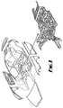
- FIG. 1 Such a floor pan 1 is illustrated in Figure 1 and as can be seen has a complex shape.
- a continuous length of carbon fibre (not shown) is fed to a robot head at which it is cut/sheared into predetermined lengths, aligned and sprayed into a moulding tool.
- the position and angle of the head in relation to the moulding tool cavity may be varied as desired so that the individual shortened fibres are laid in the moulding tool cavity at the desired position and to the desired density and thickness.
- the fibres are preferably substantially aligned although full alignment is not necessary to achieve significant strength.
- the desired strength of the moulded product may be optimized by spraying different lengths of shortened fibre or modifying the fibre alignment for additional layers.
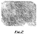
- Figure 2 diagrammatically shows a layer 30 of fibres 31 in a moulding tool.
- the surface is partially evacuated.
- Mechanical methods work with long fibres and fibre alignment reduces tow size effects. Increasing alignment enables the reduction of deposition rates which in turn leads to both process and cost savings.
- the fibres are covered and fully encased with a layer of curable resin, preferably epoxy.
- the resin is substantially cured and the finished product removed from the mould.
- a piece of material made of carbon fibre is first produced. This material may be woven or non woven but in either case it is necessary to cut the material, usually using an existing pattern before placing it in and fitting it to the moulding tool.
- This dual step of first of all producing a piece of woven/non-woven material and then subsequently cutting it to a desired shape is wasteful not only in time and effort but also in material waste. Both of these steps are effectively eliminated in the method of the invention. This can lead to a reduction in material wastage approaching 40%.
- the length of the cut/sheared fibres can be varied as desired.
- Exemplary fibre lengths are 115mm, 58mm, 28mm and 14mm.
- the superficial fibre density may also be chosen as desired.
- Exemplary fibre densities are 1500gsm (grams per square metre) and 2500 gsm.
- directionality is important.
- the limits for levels of directionality can be determined by testing.
- Directionality levels are dependant upon processing speed and deposition rates can be determined for different levels of directionality.
- Tests may be carried out on products made in accordance with the above process to determine:-
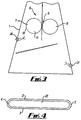
- the apparatus comprises a housing 1.
- This has a downwardly divergent shape in side elevation and a lozenge shape in cross section (as can be seen from Figure 4 ).
- the proportions of the housing 1 contribute to the consistent and smooth distribution of shortened fibres.
- the lozenge shape outlet/delivery slot in cross section (as shown in Figure 4 ) determines the principal alignment of the alignment of the shortened fibres when deposited into the moulding tool.
- the lozenge shape comprises two parallel sides 2 and 3 joined at opposite ends respectively by semi-circular portions 4 and 5.
- a cutting/shearing head 6 is disposed within the housing 1.
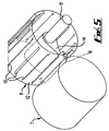
- the head 6 comprises two rollers 7 and 8 defining a nip 9 therebetween.
- Roller 7 is a pressure roller and comprises a cylindrical tyre 10 mounted on a cylindrical support 11.
- the tyre is made of rubber or other suitable material.
- Roller 8 is a blade housing roller. This comprises a cylindrical housing 12. Blades are retained in the blade housing roller 8 which is made from hard but resilient material such as rubber The diameter of the two rollers 7 and 8 is the same.
- Housing 12 is formed with a number of through elongate slots 13 extending axially of the cylinder of the housing and disposed at circumferentially spaced intervals around the cylinder.
- a cam 14 mounted on a camshaft 15 via splines (not shown). The camshaft is disposed to be driven by a stepper motor (not shown) at one of a range of speeds.
- a plurality of blades 16 (only one shown) is associated with respective slots 13, and are disposed to be extended through their corresponding slots 13 sequentially by the action of the cam as it is rotated within the housing 8 by means of the camshaft 15 driven by the stepper motor in order to cut/shear fibre passing through the nip formed between the rollers 7 and 8.
- the resilience of the rubber of the housing 8 allows that blade to return to its retracted inoperative position.
- the number of slots 13 and blades 16 may be varied as desired.
- the cam lift provided by the cam 14 is circa 2 to 3mm but again this may be varied as desired.
- the diameter of the rollers 7 and 8 is circa 30mm but this may also be varied as desired.
- the cam has a single lobe but multi lobe cam may be used if shorter fibre lengths are desired.
- the cam lift for the cutting blade must be sufficient to cut through the fibre and have accommodation of circa 0.2mm in the pressure roller (7).
- the centres of rotation for rollers (7) and (8) can be adjusted so that the nip on the chosen fibre diameter is adequate to ensure consistency and meet the cutting control criteria described above.
- the rollers 7 and 8 are driven at the same speed which is independent of the camshaft speed.
- the circumferential speed of the surfaces of the rollers determines the rate of feed of fibre fed through them.
- the precise length of fibre fed between the rollers and cut/sheared by the cam actuated blades extending through their corresponding slots is determined.
- the rollers 7 and 8 project the shortened lengths towards the delivery slot. In the particular orientation shown where the slot is in a lower position than the rollers 7 and 8 gravity will also assist. However, the slot could be higher than the rollers 7 and 8.
- Shortened fibres produced by the cutting/shearing rollers 7 and 8 fall under gravity towards the base of the housing under the action of gravity. Their passage is influenced by air jets emanating from four air jet apertures extending through the wall of the housing 1 and arranged in two pairs 20 and 21 disposed respectively in the upper and lower parts of the housing 1. Only one aperture of each pair is shown. Apertures 20 are disposed slightly below the level at which the shortened lengths of fibre are projected from between the rollers 7 and 8. The air jets through apertures 20 are activated as trailing elements relative to the movement of the robot head and the air jets through the apertures 21 are activated on the leading face of motion. The purpose of the air jets through apertures 20 is to spread the lengths of fibre.
- Apertures 21 are disposed at a lower level than apertures 20.
- the purpose of the air jets through apertures 21 is to rotate and align the shortened lengths of fibre to the direction of and within an outlet slot 22 which is defined between parallel walls 2 and 3.
- the size of slot 22, the distance between the rollers 7 and 8 and the slot 22, and the air pressure of the jets through the apertures 20 and 21 are adjusted to suit the fibre length and optimize the desired fibre distribution.
- the carbon fibre may be impregnated or coated with ferric powder and the moulding tool surface (electro) magnetized.
- the carbon fibre may be coated with a compatible crystalline epoxy powder and the moulding tool surface heated so that on deposition, the carbon fibre is retained at the surface and the mould integration started prior to the full application and curing of the bonding resin.
- a mist layer of compatible epoxy is applied in front of the shortened lengths of deposited carbon fibre. It is then retained at the surface and the moulding process started prior to the full application and curing of the bonding resin.
Landscapes
- Engineering & Computer Science (AREA)
- Chemical & Material Sciences (AREA)
- Composite Materials (AREA)
- Mechanical Engineering (AREA)
- Textile Engineering (AREA)
- Moulding By Coating Moulds (AREA)
Applications Claiming Priority (2)
| Application Number | Priority Date | Filing Date | Title |
|---|---|---|---|
| GBGB0623047.8A GB0623047D0 (en) | 2006-11-18 | 2006-11-18 | A moulded product and method of producing it |
| PCT/GB2007/004392 WO2008059273A1 (en) | 2006-11-18 | 2007-11-16 | A moulded product and method of producing it |
Publications (2)
| Publication Number | Publication Date |
|---|---|
| EP2125340A1 EP2125340A1 (en) | 2009-12-02 |
| EP2125340B1 true EP2125340B1 (en) | 2016-06-08 |
Family
ID=37605539
Family Applications (1)
| Application Number | Title | Priority Date | Filing Date |
|---|---|---|---|
| EP07824611.3A Not-in-force EP2125340B1 (en) | 2006-11-18 | 2007-11-16 | Method of producing a moulded product |
Country Status (6)
| Country | Link |
|---|---|
| US (1) | US8591781B2 (enExample) |
| EP (1) | EP2125340B1 (enExample) |
| JP (1) | JP5416592B2 (enExample) |
| CN (1) | CN101588914B (enExample) |
| GB (1) | GB0623047D0 (enExample) |
| WO (1) | WO2008059273A1 (enExample) |
Families Citing this family (5)
| Publication number | Priority date | Publication date | Assignee | Title |
|---|---|---|---|---|
| GB0623047D0 (en) * | 2006-11-18 | 2006-12-27 | Bentley Motors Ltd | A moulded product and method of producing it |
| CN102609051B (zh) * | 2011-01-20 | 2015-03-11 | 群达塑胶电子(深圳)有限公司 | 一种碳纤维笔记本电脑外壳及其制造方法 |
| US8978536B2 (en) | 2012-04-30 | 2015-03-17 | Future Force Innovation, Inc. | Material for providing blast and projectile impact protection |
| CN107443721A (zh) * | 2013-07-17 | 2017-12-08 | 马克弗盖德公司 | 用于纤维增强的添加制造的装置 |
| CN109732807B (zh) * | 2019-02-27 | 2023-06-20 | 南京特塑复合材料有限公司 | 一种连续纤维多运动状态的椭圆浸渍装置 |
Citations (1)
| Publication number | Priority date | Publication date | Assignee | Title |
|---|---|---|---|---|
| JP2010510086A (ja) * | 2006-11-18 | 2010-04-02 | ベントレー モーターズ リミテッド | モールド製品及びその製造方法 |
Family Cites Families (16)
| Publication number | Priority date | Publication date | Assignee | Title |
|---|---|---|---|---|
| JPS5532529B2 (enExample) | 1973-07-04 | 1980-08-26 | ||
| JPS5739272A (en) | 1980-08-15 | 1982-03-04 | Toray Industries | Apparatus for arranging staple fiber |
| US5352517A (en) * | 1986-03-24 | 1994-10-04 | Ensci, Inc. | Iron oxide coated substrates |
| JPS63302024A (ja) * | 1987-06-02 | 1988-12-08 | Sekisui Chem Co Ltd | 繊維強化プラスチック成形品の製造方法及びその装置 |
| JPH0258914A (ja) | 1988-08-24 | 1990-02-28 | Murata Mfg Co Ltd | 圧電共振装置 |
| JPH0258914U (enExample) * | 1988-10-20 | 1990-04-27 | ||
| WO1991012944A1 (en) | 1990-02-23 | 1991-09-05 | Wellman Machinery Of Michigan | Apparatus and method for applying preform fibers |
| US5229052A (en) * | 1990-02-23 | 1993-07-20 | Wellman Machinery Of Michigan, Inc. | Apparatus and method for applying multiple type fibers to a foraminous surface |
| JPH04244833A (ja) * | 1991-01-29 | 1992-09-01 | Daikyo Inc | Frp成形品の製造方法及びそのための型装置 |
| JPH0516251A (ja) | 1991-07-16 | 1993-01-26 | Hitachi Chem Co Ltd | 繊維強化プラスチツク成形品の製造方法 |
| BE1010823A3 (nl) | 1996-12-24 | 1999-02-02 | Dsm Nv | Constructieveer van met vezels versterkte kunststof. |
| US6029897A (en) | 1998-03-19 | 2000-02-29 | N.V. Owens-Corning S.A. | Method of dispensing chopped reinforcement strand using a vortex nozzle |
| WO2002053335A1 (en) * | 2001-01-08 | 2002-07-11 | Brunswick Corporation | Method of making preforms |
| JP2004237535A (ja) | 2003-02-05 | 2004-08-26 | Toray Ind Inc | プリフォームの製造方法および製造装置 |
| US20050161861A1 (en) | 2003-09-26 | 2005-07-28 | Brunswick Corporation | Apparatus and method for making preforms in mold |
| GB0623046D0 (en) * | 2006-11-18 | 2006-12-27 | Bentley Motors Ltd | Apparatus for cutting and/or shearing fibre |
-
2006
- 2006-11-18 GB GBGB0623047.8A patent/GB0623047D0/en not_active Ceased
-
2007
- 2007-11-16 US US12/515,307 patent/US8591781B2/en active Active
- 2007-11-16 EP EP07824611.3A patent/EP2125340B1/en not_active Not-in-force
- 2007-11-16 JP JP2009536796A patent/JP5416592B2/ja not_active Expired - Fee Related
- 2007-11-16 WO PCT/GB2007/004392 patent/WO2008059273A1/en not_active Ceased
- 2007-11-16 CN CN2007800501357A patent/CN101588914B/zh not_active Expired - Fee Related
Patent Citations (1)
| Publication number | Priority date | Publication date | Assignee | Title |
|---|---|---|---|---|
| JP2010510086A (ja) * | 2006-11-18 | 2010-04-02 | ベントレー モーターズ リミテッド | モールド製品及びその製造方法 |
Also Published As
| Publication number | Publication date |
|---|---|
| CN101588914B (zh) | 2012-11-14 |
| US20100098944A1 (en) | 2010-04-22 |
| JP5416592B2 (ja) | 2014-02-12 |
| JP2010510086A (ja) | 2010-04-02 |
| CN101588914A (zh) | 2009-11-25 |
| EP2125340A1 (en) | 2009-12-02 |
| GB0623047D0 (en) | 2006-12-27 |
| WO2008059273A1 (en) | 2008-05-22 |
| US8591781B2 (en) | 2013-11-26 |
Similar Documents
| Publication | Publication Date | Title |
|---|---|---|
| KR102091993B1 (ko) | 섬유 프리폼들을 제조하기 위한 방법 | |
| JP7017269B2 (ja) | 3dプリント工程による複合材製品の製造方法及びその実施装置 | |
| EP2125340B1 (en) | Method of producing a moulded product | |
| CA2914512C (en) | Methods for fiber reinforced additive manufacturing | |
| CA2752906C (en) | Method and apparatus for making fiber reinforced composite tubes | |
| CN105916788A (zh) | 用于制造纤维板坯的设备和方法 | |
| JP2014515996A (ja) | 多層のプリフォームの少なくとも1つの層にバインダを供給する方法、設備及び装置 | |
| CN105142882A (zh) | 用于制造纤维复合构件的方法和设备以及纤维复合构件 | |
| EP0907475B1 (en) | Method for dispensing resinated reinforcement fibers | |
| US20100116795A1 (en) | Apparatus for cutting and/or shearing fibre | |
| MXPA03006134A (es) | Metodo para hacer pre-formas. | |
| CA2272966C (en) | Twin chopper device for spray-up molding | |
| US20210276688A1 (en) | Shaped Composite Vehicle Skins and Method for High Rate Manufacturing of Same | |
| PL1623807T5 (pl) | Sposób i urządzenie do wytwarzania korpusu z tworzywa drzewnego | |
| WO1998042495A1 (en) | Process and apparatus for manufacture of a component | |
| MXPA98010297A (en) | Method for distributing resin reinforcement fibers |
Legal Events
| Date | Code | Title | Description |
|---|---|---|---|
| PUAI | Public reference made under article 153(3) epc to a published international application that has entered the european phase |
Free format text: ORIGINAL CODE: 0009012 |
|
| 17P | Request for examination filed |
Effective date: 20090618 |
|
| AK | Designated contracting states |
Kind code of ref document: A1 Designated state(s): AT BE BG CH CY CZ DE DK EE ES FI FR GB GR HU IE IS IT LI LT LU LV MC MT NL PL PT RO SE SI SK TR |
|
| DAX | Request for extension of the european patent (deleted) | ||
| 17Q | First examination report despatched |
Effective date: 20110404 |
|
| GRAP | Despatch of communication of intention to grant a patent |
Free format text: ORIGINAL CODE: EPIDOSNIGR1 |
|
| INTG | Intention to grant announced |
Effective date: 20160127 |
|
| GRAS | Grant fee paid |
Free format text: ORIGINAL CODE: EPIDOSNIGR3 |
|
| GRAA | (expected) grant |
Free format text: ORIGINAL CODE: 0009210 |
|
| AK | Designated contracting states |
Kind code of ref document: B1 Designated state(s): AT BE BG CH CY CZ DE DK EE ES FI FR GB GR HU IE IS IT LI LT LU LV MC MT NL PL PT RO SE SI SK TR |
|
| REG | Reference to a national code |
Ref country code: GB Ref legal event code: FG4D |
|
| REG | Reference to a national code |
Ref country code: CH Ref legal event code: EP |
|
| REG | Reference to a national code |
Ref country code: IE Ref legal event code: FG4D |
|
| REG | Reference to a national code |
Ref country code: AT Ref legal event code: REF Ref document number: 804896 Country of ref document: AT Kind code of ref document: T Effective date: 20160715 |
|
| REG | Reference to a national code |
Ref country code: DE Ref legal event code: R096 Ref document number: 602007046611 Country of ref document: DE |
|
| REG | Reference to a national code |
Ref country code: LT Ref legal event code: MG4D |
|
| REG | Reference to a national code |
Ref country code: NL Ref legal event code: MP Effective date: 20160608 |
|
| REG | Reference to a national code |
Ref country code: FR Ref legal event code: PLFP Year of fee payment: 10 |
|
| PG25 | Lapsed in a contracting state [announced via postgrant information from national office to epo] |
Ref country code: LT Free format text: LAPSE BECAUSE OF FAILURE TO SUBMIT A TRANSLATION OF THE DESCRIPTION OR TO PAY THE FEE WITHIN THE PRESCRIBED TIME-LIMIT Effective date: 20160608 Ref country code: FI Free format text: LAPSE BECAUSE OF FAILURE TO SUBMIT A TRANSLATION OF THE DESCRIPTION OR TO PAY THE FEE WITHIN THE PRESCRIBED TIME-LIMIT Effective date: 20160608 |
|
| PGFP | Annual fee paid to national office [announced via postgrant information from national office to epo] |
Ref country code: GB Payment date: 20160923 Year of fee payment: 10 |
|
| REG | Reference to a national code |
Ref country code: AT Ref legal event code: MK05 Ref document number: 804896 Country of ref document: AT Kind code of ref document: T Effective date: 20160608 |
|
| PG25 | Lapsed in a contracting state [announced via postgrant information from national office to epo] |
Ref country code: SE Free format text: LAPSE BECAUSE OF FAILURE TO SUBMIT A TRANSLATION OF THE DESCRIPTION OR TO PAY THE FEE WITHIN THE PRESCRIBED TIME-LIMIT Effective date: 20160608 Ref country code: ES Free format text: LAPSE BECAUSE OF FAILURE TO SUBMIT A TRANSLATION OF THE DESCRIPTION OR TO PAY THE FEE WITHIN THE PRESCRIBED TIME-LIMIT Effective date: 20160608 Ref country code: NL Free format text: LAPSE BECAUSE OF FAILURE TO SUBMIT A TRANSLATION OF THE DESCRIPTION OR TO PAY THE FEE WITHIN THE PRESCRIBED TIME-LIMIT Effective date: 20160608 Ref country code: LV Free format text: LAPSE BECAUSE OF FAILURE TO SUBMIT A TRANSLATION OF THE DESCRIPTION OR TO PAY THE FEE WITHIN THE PRESCRIBED TIME-LIMIT Effective date: 20160608 Ref country code: GR Free format text: LAPSE BECAUSE OF FAILURE TO SUBMIT A TRANSLATION OF THE DESCRIPTION OR TO PAY THE FEE WITHIN THE PRESCRIBED TIME-LIMIT Effective date: 20160909 |
|
| PG25 | Lapsed in a contracting state [announced via postgrant information from national office to epo] |
Ref country code: EE Free format text: LAPSE BECAUSE OF FAILURE TO SUBMIT A TRANSLATION OF THE DESCRIPTION OR TO PAY THE FEE WITHIN THE PRESCRIBED TIME-LIMIT Effective date: 20160608 Ref country code: RO Free format text: LAPSE BECAUSE OF FAILURE TO SUBMIT A TRANSLATION OF THE DESCRIPTION OR TO PAY THE FEE WITHIN THE PRESCRIBED TIME-LIMIT Effective date: 20160608 Ref country code: SK Free format text: LAPSE BECAUSE OF FAILURE TO SUBMIT A TRANSLATION OF THE DESCRIPTION OR TO PAY THE FEE WITHIN THE PRESCRIBED TIME-LIMIT Effective date: 20160608 Ref country code: IT Free format text: LAPSE BECAUSE OF FAILURE TO SUBMIT A TRANSLATION OF THE DESCRIPTION OR TO PAY THE FEE WITHIN THE PRESCRIBED TIME-LIMIT Effective date: 20160608 Ref country code: IS Free format text: LAPSE BECAUSE OF FAILURE TO SUBMIT A TRANSLATION OF THE DESCRIPTION OR TO PAY THE FEE WITHIN THE PRESCRIBED TIME-LIMIT Effective date: 20161008 Ref country code: CZ Free format text: LAPSE BECAUSE OF FAILURE TO SUBMIT A TRANSLATION OF THE DESCRIPTION OR TO PAY THE FEE WITHIN THE PRESCRIBED TIME-LIMIT Effective date: 20160608 |
|
| PGFP | Annual fee paid to national office [announced via postgrant information from national office to epo] |
Ref country code: FR Payment date: 20161017 Year of fee payment: 10 |
|
| PG25 | Lapsed in a contracting state [announced via postgrant information from national office to epo] |
Ref country code: PL Free format text: LAPSE BECAUSE OF FAILURE TO SUBMIT A TRANSLATION OF THE DESCRIPTION OR TO PAY THE FEE WITHIN THE PRESCRIBED TIME-LIMIT Effective date: 20160608 Ref country code: AT Free format text: LAPSE BECAUSE OF FAILURE TO SUBMIT A TRANSLATION OF THE DESCRIPTION OR TO PAY THE FEE WITHIN THE PRESCRIBED TIME-LIMIT Effective date: 20160608 Ref country code: BE Free format text: LAPSE BECAUSE OF FAILURE TO SUBMIT A TRANSLATION OF THE DESCRIPTION OR TO PAY THE FEE WITHIN THE PRESCRIBED TIME-LIMIT Effective date: 20160608 Ref country code: PT Free format text: LAPSE BECAUSE OF FAILURE TO SUBMIT A TRANSLATION OF THE DESCRIPTION OR TO PAY THE FEE WITHIN THE PRESCRIBED TIME-LIMIT Effective date: 20161010 |
|
| REG | Reference to a national code |
Ref country code: DE Ref legal event code: R097 Ref document number: 602007046611 Country of ref document: DE |
|
| PLBE | No opposition filed within time limit |
Free format text: ORIGINAL CODE: 0009261 |
|
| STAA | Information on the status of an ep patent application or granted ep patent |
Free format text: STATUS: NO OPPOSITION FILED WITHIN TIME LIMIT |
|
| PGFP | Annual fee paid to national office [announced via postgrant information from national office to epo] |
Ref country code: DE Payment date: 20170125 Year of fee payment: 10 |
|
| 26N | No opposition filed |
Effective date: 20170309 |
|
| PG25 | Lapsed in a contracting state [announced via postgrant information from national office to epo] |
Ref country code: DK Free format text: LAPSE BECAUSE OF FAILURE TO SUBMIT A TRANSLATION OF THE DESCRIPTION OR TO PAY THE FEE WITHIN THE PRESCRIBED TIME-LIMIT Effective date: 20160608 Ref country code: SI Free format text: LAPSE BECAUSE OF FAILURE TO SUBMIT A TRANSLATION OF THE DESCRIPTION OR TO PAY THE FEE WITHIN THE PRESCRIBED TIME-LIMIT Effective date: 20160608 |
|
| REG | Reference to a national code |
Ref country code: CH Ref legal event code: PL |
|
| PG25 | Lapsed in a contracting state [announced via postgrant information from national office to epo] |
Ref country code: CH Free format text: LAPSE BECAUSE OF NON-PAYMENT OF DUE FEES Effective date: 20161130 Ref country code: LI Free format text: LAPSE BECAUSE OF NON-PAYMENT OF DUE FEES Effective date: 20161130 |
|
| REG | Reference to a national code |
Ref country code: IE Ref legal event code: MM4A |
|
| PG25 | Lapsed in a contracting state [announced via postgrant information from national office to epo] |
Ref country code: LU Free format text: LAPSE BECAUSE OF NON-PAYMENT OF DUE FEES Effective date: 20161130 |
|
| PG25 | Lapsed in a contracting state [announced via postgrant information from national office to epo] |
Ref country code: IE Free format text: LAPSE BECAUSE OF NON-PAYMENT OF DUE FEES Effective date: 20161116 |
|
| PG25 | Lapsed in a contracting state [announced via postgrant information from national office to epo] |
Ref country code: CY Free format text: LAPSE BECAUSE OF FAILURE TO SUBMIT A TRANSLATION OF THE DESCRIPTION OR TO PAY THE FEE WITHIN THE PRESCRIBED TIME-LIMIT Effective date: 20160608 Ref country code: HU Free format text: LAPSE BECAUSE OF FAILURE TO SUBMIT A TRANSLATION OF THE DESCRIPTION OR TO PAY THE FEE WITHIN THE PRESCRIBED TIME-LIMIT; INVALID AB INITIO Effective date: 20071116 |
|
| REG | Reference to a national code |
Ref country code: DE Ref legal event code: R119 Ref document number: 602007046611 Country of ref document: DE |
|
| PG25 | Lapsed in a contracting state [announced via postgrant information from national office to epo] |
Ref country code: TR Free format text: LAPSE BECAUSE OF FAILURE TO SUBMIT A TRANSLATION OF THE DESCRIPTION OR TO PAY THE FEE WITHIN THE PRESCRIBED TIME-LIMIT Effective date: 20160608 Ref country code: MC Free format text: LAPSE BECAUSE OF FAILURE TO SUBMIT A TRANSLATION OF THE DESCRIPTION OR TO PAY THE FEE WITHIN THE PRESCRIBED TIME-LIMIT Effective date: 20160608 |
|
| GBPC | Gb: european patent ceased through non-payment of renewal fee |
Effective date: 20171116 |
|
| PG25 | Lapsed in a contracting state [announced via postgrant information from national office to epo] |
Ref country code: BG Free format text: LAPSE BECAUSE OF FAILURE TO SUBMIT A TRANSLATION OF THE DESCRIPTION OR TO PAY THE FEE WITHIN THE PRESCRIBED TIME-LIMIT Effective date: 20160608 |
|
| REG | Reference to a national code |
Ref country code: FR Ref legal event code: ST Effective date: 20180731 |
|
| PG25 | Lapsed in a contracting state [announced via postgrant information from national office to epo] |
Ref country code: MT Free format text: LAPSE BECAUSE OF NON-PAYMENT OF DUE FEES Effective date: 20161116 |
|
| PG25 | Lapsed in a contracting state [announced via postgrant information from national office to epo] |
Ref country code: FR Free format text: LAPSE BECAUSE OF NON-PAYMENT OF DUE FEES Effective date: 20171130 Ref country code: DE Free format text: LAPSE BECAUSE OF NON-PAYMENT OF DUE FEES Effective date: 20180602 |
|
| PG25 | Lapsed in a contracting state [announced via postgrant information from national office to epo] |
Ref country code: GB Free format text: LAPSE BECAUSE OF NON-PAYMENT OF DUE FEES Effective date: 20171116 |