EP2125274B1 - Method and apparatus for producing a shaped bore - Google Patents
Method and apparatus for producing a shaped bore Download PDFInfo
- Publication number
- EP2125274B1 EP2125274B1 EP08743636A EP08743636A EP2125274B1 EP 2125274 B1 EP2125274 B1 EP 2125274B1 EP 08743636 A EP08743636 A EP 08743636A EP 08743636 A EP08743636 A EP 08743636A EP 2125274 B1 EP2125274 B1 EP 2125274B1
- Authority
- EP
- European Patent Office
- Prior art keywords
- tool
- fluid
- conduit
- cam
- vents
- Prior art date
- Legal status (The legal status is an assumption and is not a legal conclusion. Google has not performed a legal analysis and makes no representation as to the accuracy of the status listed.)
- Active
Links
Images


Classifications
-
- B—PERFORMING OPERATIONS; TRANSPORTING
- B23—MACHINE TOOLS; METAL-WORKING NOT OTHERWISE PROVIDED FOR
- B23B—TURNING; BORING
- B23B29/00—Holders for non-rotary cutting tools; Boring bars or boring heads; Accessories for tool holders
- B23B29/03—Boring heads
- B23B29/034—Boring heads with tools moving radially, e.g. for making chamfers or undercuttings
- B23B29/03432—Boring heads with tools moving radially, e.g. for making chamfers or undercuttings radially adjustable during manufacturing
-
- B—PERFORMING OPERATIONS; TRANSPORTING
- B23—MACHINE TOOLS; METAL-WORKING NOT OTHERWISE PROVIDED FOR
- B23B—TURNING; BORING
- B23B41/00—Boring or drilling machines or devices specially adapted for particular work; Accessories specially adapted therefor
- B23B41/04—Boring or drilling machines or devices specially adapted for particular work; Accessories specially adapted therefor for boring polygonal or other non-circular holes
-
- B—PERFORMING OPERATIONS; TRANSPORTING
- B23—MACHINE TOOLS; METAL-WORKING NOT OTHERWISE PROVIDED FOR
- B23D—PLANING; SLOTTING; SHEARING; BROACHING; SAWING; FILING; SCRAPING; LIKE OPERATIONS FOR WORKING METAL BY REMOVING MATERIAL, NOT OTHERWISE PROVIDED FOR
- B23D77/00—Reaming tools
- B23D77/02—Reamers with inserted cutting edges
- B23D77/04—Reamers with inserted cutting edges with cutting edges adjustable to different diameters along the whole cutting length
-
- B—PERFORMING OPERATIONS; TRANSPORTING
- B23—MACHINE TOOLS; METAL-WORKING NOT OTHERWISE PROVIDED FOR
- B23B—TURNING; BORING
- B23B2270/00—Details of turning, boring or drilling machines, processes or tools not otherwise provided for
- B23B2270/24—Tool, chuck or other device activated by the coolant or lubrication system of the machine tool
-
- Y—GENERAL TAGGING OF NEW TECHNOLOGICAL DEVELOPMENTS; GENERAL TAGGING OF CROSS-SECTIONAL TECHNOLOGIES SPANNING OVER SEVERAL SECTIONS OF THE IPC; TECHNICAL SUBJECTS COVERED BY FORMER USPC CROSS-REFERENCE ART COLLECTIONS [XRACs] AND DIGESTS
- Y10—TECHNICAL SUBJECTS COVERED BY FORMER USPC
- Y10S—TECHNICAL SUBJECTS COVERED BY FORMER USPC CROSS-REFERENCE ART COLLECTIONS [XRACs] AND DIGESTS
- Y10S408/00—Cutting by use of rotating axially moving tool
- Y10S408/714—Resilient tool or tool-support
-
- Y—GENERAL TAGGING OF NEW TECHNOLOGICAL DEVELOPMENTS; GENERAL TAGGING OF CROSS-SECTIONAL TECHNOLOGIES SPANNING OVER SEVERAL SECTIONS OF THE IPC; TECHNICAL SUBJECTS COVERED BY FORMER USPC CROSS-REFERENCE ART COLLECTIONS [XRACs] AND DIGESTS
- Y10—TECHNICAL SUBJECTS COVERED BY FORMER USPC
- Y10T—TECHNICAL SUBJECTS COVERED BY FORMER US CLASSIFICATION
- Y10T408/00—Cutting by use of rotating axially moving tool
- Y10T408/03—Processes
-
- Y—GENERAL TAGGING OF NEW TECHNOLOGICAL DEVELOPMENTS; GENERAL TAGGING OF CROSS-SECTIONAL TECHNOLOGIES SPANNING OVER SEVERAL SECTIONS OF THE IPC; TECHNICAL SUBJECTS COVERED BY FORMER USPC CROSS-REFERENCE ART COLLECTIONS [XRACs] AND DIGESTS
- Y10—TECHNICAL SUBJECTS COVERED BY FORMER USPC
- Y10T—TECHNICAL SUBJECTS COVERED BY FORMER US CLASSIFICATION
- Y10T408/00—Cutting by use of rotating axially moving tool
- Y10T408/44—Cutting by use of rotating axially moving tool with means to apply transient, fluent medium to work or product
- Y10T408/45—Cutting by use of rotating axially moving tool with means to apply transient, fluent medium to work or product including Tool with duct
- Y10T408/455—Conducting channel extending to end of Tool
-
- Y—GENERAL TAGGING OF NEW TECHNOLOGICAL DEVELOPMENTS; GENERAL TAGGING OF CROSS-SECTIONAL TECHNOLOGIES SPANNING OVER SEVERAL SECTIONS OF THE IPC; TECHNICAL SUBJECTS COVERED BY FORMER USPC CROSS-REFERENCE ART COLLECTIONS [XRACs] AND DIGESTS
- Y10—TECHNICAL SUBJECTS COVERED BY FORMER USPC
- Y10T—TECHNICAL SUBJECTS COVERED BY FORMER US CLASSIFICATION
- Y10T408/00—Cutting by use of rotating axially moving tool
- Y10T408/65—Means to drive tool
-
- Y—GENERAL TAGGING OF NEW TECHNOLOGICAL DEVELOPMENTS; GENERAL TAGGING OF CROSS-SECTIONAL TECHNOLOGIES SPANNING OVER SEVERAL SECTIONS OF THE IPC; TECHNICAL SUBJECTS COVERED BY FORMER USPC CROSS-REFERENCE ART COLLECTIONS [XRACs] AND DIGESTS
- Y10—TECHNICAL SUBJECTS COVERED BY FORMER USPC
- Y10T—TECHNICAL SUBJECTS COVERED BY FORMER US CLASSIFICATION
- Y10T408/00—Cutting by use of rotating axially moving tool
- Y10T408/83—Tool-support with means to move Tool relative to tool-support
- Y10T408/85—Tool-support with means to move Tool relative to tool-support to move radially
- Y10T408/858—Moving means including wedge, screw or cam
- Y10T408/8583—Moving means including wedge, screw or cam with resiliently urged Tool
- Y10T408/85843—Resilient Tool or tool-support
-
- Y—GENERAL TAGGING OF NEW TECHNOLOGICAL DEVELOPMENTS; GENERAL TAGGING OF CROSS-SECTIONAL TECHNOLOGIES SPANNING OVER SEVERAL SECTIONS OF THE IPC; TECHNICAL SUBJECTS COVERED BY FORMER USPC CROSS-REFERENCE ART COLLECTIONS [XRACs] AND DIGESTS
- Y10—TECHNICAL SUBJECTS COVERED BY FORMER USPC
- Y10T—TECHNICAL SUBJECTS COVERED BY FORMER US CLASSIFICATION
- Y10T82/00—Turning
- Y10T82/12—Radially moving rotating tool inside bore
- Y10T82/125—Tool simultaneously moving axially
- Y10T82/128—Pivoted to tool-carrier
Definitions
- WO 2004/022271 A1 I discloses a rotating cutting tool, which is selectively biasable in the radial direction based on the angular orientation of a cutting blade, which may be used to create to create a non-axis symmetric feature in a bore.
- the radial position of the cutting blade may be controlled by selectively pressurized fluid whose pressure is varied based on the angular orientation of the tool.
- a plurality of vents may be selectively covered and uncovered by means of a sleeve to vent pressurized fluid to vary the pressure thereof.
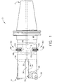
- FIG. 1 is a partial cross-sectional side view of a tool constructed in accordance with an exemplary embodiment of the present invention
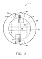
- FIG. 2 is an end view of the tool of FIG. 1 ;
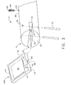
- FIG. 3 is an exploded perspective view of the tool of FIG. 1 ;
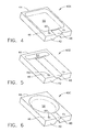
- FIG. 4 is a perspective view of an embodiment of a plate for the tool of FIG. 1 ;
- FIG. 5 is a perspective view of an alternate embodiment of a plate for the tool of FIG. 1 ;
- FIG. 6 is a perspective view of an alternate embodiment of a plate for the tool of FIG. 1 ;
- FIG. 7 is a front elevational view of an alternate embodiment of a plate for the tool of FIG. 1 , configured to receive a wafer;
- FIG. 8 is a cross-sectional side view of the plate of FIG. 7 , taken along line 8-8;
- FIG. 9 is a perspective view of an embodiment of a wafer configured to fit in the plate of FIG. 7 ;
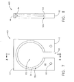
- FIG. 10 is a perspective cross-sectional view of an exemplary hydraulic cam.
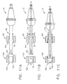
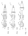
- FIGS. 11A through 11F are series views of the tool of FIG 1 and the cam of FIG. 10 in an exemplary use.
- FIGS. 1 and 2 show tool (2) having proximal end (4) and distal end (6).
- Conduit (8) runs along the axis of tool (2) from proximal end (4) toward distal end (6).
- the term "conduit” is intended to include any channel or other structure or configuration through which fluid (e.g., liquid, etc.), materials, and the like may be conveyed, passed, or otherwise communicated.
- conduit (8) is configured to permit communication of a fluid medium through tool (2).
- suitable configurations may be used to permit fluid communication.
- tool (2) is adapted for use with a machining station (not shown) having a selectively rotatable machine spindle, and that may quickly and easily receive and secure one of a plurality of tools for various operations (e.g., rotating, vibrating, oscillating, etc.).
- a machining station may have a synchronized system, such as an automatic tool changer for quickly and easily interchanging and utilizing multiple machining tools at one machining station, thereby allowing the machining station to provide greater utility or range of operations.
- Tool (2) is further configured for use with a source of a pressurized fluid medium for communication to conduit (8) in tool (2).
- the machining station permits a user to selectively control both the speed of tool (2) rotation and the pressure of the fluid medium being communicated to conduit (8).
- the fluid medium is capable of providing lubrication and/or cooling of at least a portion of the interface between tool (2) and a workpiece (not shown).
- tool (2) is attachable to a selectively rotatable spindle at proximal end (4), and receives a pressurized fluid medium at proximal end (4).
- the interface of machining station and proximal end (4) of tool (2) of the present example is quite similar to the corresponding interface described in U.S. Patent No. 6,270,295 .
- Distal end (6) of tool (2) includes a pair of opposing cutting blades (20) mounted on extremities (26).
- FIG. 1 includes a partial cross section of extremity (26) to show cutting blade (20).
- a slot (30) is defined between pair of extremities (26), and has a plate (40A) (not shown in FIG. 1 ) disposed therein.
- dowel pins (70) may be used to hold plate (40A) within slot (30).
- Other suitable distal end (6) features and configurations will be apparent to those of ordinary skill in the art, including but not limited to inserted members other than plate (40A) and alternatives for dowel pins (70).
- Slot (30) is generally rectangular, and is defined by proximal surface (32) and two side surfaces (36).
- Proximal surface (32) has opening (34) along the axis of tool (2) for fluid communication with conduit (8).
- Each side surface (36) has a pair of pin openings (38).
- Each pin opening (38) extends completely through corresponding extremity (26) in a direction transverse the axis of tool (2), and is configured to receive dowel pin (70).
- Other suitable slot (30) configurations will be apparent to those of ordinary skill in the art.
- distal end (6) of tool (2) may have a diameter 20,32 cm (8 inches), 5,08 cm (2 inches), 3,175 cm (1.25 inches). 2,54 cm (1inch), of approximately 20,32 cm (8 inches) 5,08 cm (2 inches), 3,175 cm (1.25 inches), 2,54 cm (1 inch), or 32 mm.
- Slot (30) may have a width (e.g., distance between side surfaces (36)) of approximately 0.9525 cm (0.375 inches) or 5mm. Of course, any other suitable dimensions may be used for tool (2) diameter and/or slot (30) width.
- Slot (30) may be 6,604 cm (2.6 inches) deep (e.g., distance from distal end of tool (6) to proximal surface (32) of slot (30) is 6,604 cm), 8,4353 cm (3.321 inches) deep, or any other suitable depth.
- Plate (40A) has proximal end (42), distal end (44), and a pair of side surfaces (46). Plate (40A) also has a pair of pin openings (60) formed through side surfaces (46), each opening (60) being configured to receive dowel pin (70). Plate (40A) is configured to fit in slot (30), such as by an interference fit. Such an interference fit may be obtained where plate (40A) has a thickness that is 0,0254 cm (0.001") greater than the width of slot (30), by way of example only. In one embodiment, slot (30) has a width of 0,94996 cm (0.374") while plate (40A) has thickness of 0,9525 cm (0.375").
- slot (30) and plate (40A) may be dimensioned such that the fit is not an interference fit.
- slot may have a width of 0,9525 cm (0.375") while plate (40A) has a thickness of 0,94996 cm (0.374").
- plate (40A) may be dimensioned such that its exposed outer surfaces are flush with or slightly recessed from the outer surfaces of tool (2).
- Tool (2) of the present example further comprises a pair of vents (80).
- Vents (80) are longitudinally positioned proximal to slot (30) in this example.
- Each vent (80) comprises a vent conduit (82) in fluid communication with conduit (8).
- Each vent conduit (82) is substantially perpendicular to conduit (8) in this example, and opens at the outer side surface (88) of tool (2).
- Each vent conduit (82) is also oriented at an angular position about the axis of tool (2) that corresponds to the angular position of cutting blades (20) about the axis of tool (2).
- vent conduits (82) may have any other suitable orientation relative to conduit (8), cutting blades (20), and/or axis of tool (2).
- a cannulated set screw (84) is provided within each vent conduit (82).
- Each cannulated set screw (84) has an orifice (86) formed therethrough, and each orifice (86) is in fluid communication with its corresponding vent conduit (82).
- Each cannulated set screw (84) in the present example is positioned within its corresponding vent conduit (82) such that a portion of each set screw (84) extends radially outward beyond outer side surface (88) of tool (2).
- cannulated set screws (84) may have any other suitable relationship with outer side surface (88) of tool (2).
- vents (80) are configured to selectively provide pressure relief for fluid communicated through conduit (8).
- FIG. 3 shows plate (40A), a simplified rendering of tool (2), and dowel pins (70) prior to insertion of plate (40A) in slot (30).
- pin openings (38) of slot (30) align with pin openings (60) of plate (40A), such that dowel pins (70) may be placed through pin openings (38, 60) to secure plate (40A) within slot (30).
- any other suitable configuration for securing plate (40A) within slot (30) may be used.
- each side surface (46) of plate (40A) has a recess (50) formed therein.
- Each recess (50) has a channel (48), also formed in respective side surface (46), leading to proximal end (42).
- Each channel (48) is configured to permit fluid communication to corresponding recess (50).
- each channel (48) will be in fluid communication with opening (34) in proximal surface (32) of slot (30), such that fluid may be communicated through conduit (8), through opening (34), and through channel (48) to reach each recess (50) in plate (40A).
- any other suitable configuration may be used to facilitate communication of a fluid medium to each recess (50).
- plate (40A) may be modular in nature, such that a variety of types of plates (40A) may be inserted in slot (30).
- An aspect of plate (40A) that may be modified for such varying plate (40A) types may be the configuration of recesses (50).
- recesses (50) may be generally rectangular in shape.
- recesses (54) in plate (40B) may be generally "T"-shaped.
- recesses (56) in plate (40C) are generally circular.
- Plate (40A) configurations may also be varied as a function of recess (50) size, in addition to, or instead of, recess (50) shape.
- recesses (50) in respective side surfaces (46) of plate (40A) have substantially the same size and shape.
- recesses (50) on plate (40A) may be sized and/or shaped differently. Still other suitable recess (50) configurations and variations will be apparent to those of ordinary skill in the art.
- Plate (40A) may be made of any suitable material or materials.
- plate (40A) may be made of steel, aluminum, plastic, or any other suitable material, including combinations thereof.
- plate (40D) is configured to receive a wafer (58).
- plate (40D) has center opening (62) formed therethrough. Opening (62) is in fluid communication with channel (48) in proximal end (42) of plate (40D). Opening (62) is defined by inner annular ridge (64), which is recessed within plate (40D) to provide recess (56A).
- Wafer (58) may be positioned within recess (56A), adjacent annular ridge (64). As shown, the shape of wafer (58) corresponds to the shape of recess (56A). While wafer (58) is shown as generally circular to correspond with generally circular recess (56A), it will be appreciated that wafer (58) may correspond to any other shape. By way of example only, wafer (58) may be generally square to correspond with generally square recess (50), generally "T"-shaped to correspond with generally "T"-shaped recess (54), or any other shape to correspond with a different recess. Alternatively, wafer (58) may be shaped differently than recess (50) in which it is disposed, such that they do not correspond.
- wafer (58) may be used with any of plates (40A-40C) that lacks opening (62).
- wafer (58) may be provided within a recess (50, 54, 56).
- wafer (58) may include a channel or conduit to facilitate entry of fluid into space between wafer (58) and recess (50), or into space adjacent to wafer (58).
- any of plates (40A-40C) may include an opening in addition to or as an alternative to recesses (50, 54, 56). Other combinations and variations will be apparent to those of ordinary skill in the art.
- annular ridge (64) is recessed 0,3175 cm (0.125") within plate (40D) (e.g., the distance between annular ridge (64) and side surface (46) is 0,3175 cm), while wafer (58) has a thickness of 0,2863 cm (0.1127").
- Recess (56A) has a diameter of 6,096 cm (2.4"), while wafer (58) has a diameter of 5,969 cm (2.35").
- recess (56A) and wafer (58) are sized such that there is an interference fit between wafer (58) and plate (40D). Still other suitable dimensions for plate (40D) and/or wafer (58) will be apparent to those of ordinary skill in the art.
- Wafer (58) configuration may be varied by size, shape, and/or by having one or more openings (68) formed in wafer (58). Such an opening (68) may permit some fluid to escape therethrough. Such escaping fluid may exert some force directly on extremity (26).
- wafer (58) with an opening (68) formed in its center may provide characteristics that differ from a wafer that has no opening.
- one wafer (58) that has an opening (68) of a first size may provide characteristics that differ from wafer (58) that has opening (68) of a different, second size.
- wafer (58) has opening (68) with a diameter of 1,2065 cm (0.475").
- the number and/or size of opening(s) (68) may vary greatly. It will be appreciated that the size, shape, and/or number of openings (68) in wafer (58) may relate to the force exerted by wafer (58) on extremity (26). In addition, the size and/or number of openings (68) in wafer (58) may relate to the amount of fluid permitted to leak from tool (2). Other embodiments and uses for opening(s) (68) in wafer (58) will be apparent to those of ordinary skill in the art.
- Wafer (58) may be made of any suitable material or materials.
- wafer (58) may be made of polyurethane, brass, or any other suitable material, including combinations thereof.
- the material of which wafer (58) is made is softer or less dense than the material of which plate (40D) is made.
- the respective materials may be of any other suitable relative hardness.
- wafer may be eliminated altogether.
- wafer shall be broadly construed to include any member that may be inserted in or otherwise engaged with recess (50, 54, 56, 56A) of plate (40A-40D).
- a user may selectively adjust the pressure of fluid being communicated to tool (2).
- the same may be true for cutting other bores.
- pressure adjustments of communicated fluid may also adjust the pressure of fluid within tool (2).
- the fluid pressure is increased in the present example, the fluid will be directed outward by recesses (50) in side surfaces (46) of plate (40A), thereby exerting an increasing, outward force against side surfaces (36) of slot (30) (e.g., outward force increases with fluid pressure).
- extremities (26) and slot (30) may constitute a selective bias portion of tool (2).
- extremities (26) and slot (30) of the present example are configured to selectively bias cutting blades (20) to a variety of use positions.
- a selective bias portion of tool (2) may include other elements or features.
- the radial positioning of cutting blades (20) with respect to the axis of tool (2) may be adjusted according to the pressure of the fluid being communicated to and through tool (2), such that increasing fluid pressure will increase the diametric distance between cutting blades (20).
- tool (2) may be used to cut or ream bores of different diameters, as the diametric distance between cutting blades (20) may be varied as a function of fluid pressure.
- extremities (26) when fluid pressure is decreased, causes extremities (26) to return back (e.g. radially inward) to their prior configuration. Such resilience may be found where tool (2) is made of steel or any other metal, alloy, or the like.
- the diametric distance between cutting blades (20) may be varied as a function of fluid pressure, and the fluid pressure may be varied by varying the pressure of fluid being communicated to conduit (8).
- the source of pressurized fluid may have a valve or other feature operable to vary the pressure of fluid being communicated to conduit (8).
- fluid pressure within tool (2) may be varied even where the pressure of fluid being communicated to conduit (8) (e.g., from the pressurized fluid source) is kept substantially constant.
- pressure variations may be selectively and controllably created within tool (2) itself, such that the pressure of fluid within one portion of conduit (8) may differ from the pressure of fluid within another portion of conduit (8).
- Such controllable pressure variations may be induced using vents (80) and a hydraulic cam (90), an example of which is shown in FIG. 10 .
- hydraulic cam (90) of the present example is generally cylindraceous, and has an interior surface (92) defining an axial opening (94) through the center of cam (90). It will be appreciated, however, that cam (90) need not be generally cylindraceous, and may have any other suitable configuration. As shown in FIGS. 11A-11F , cam (90) is configured such that at least a portion of tool (2) is fed through opening (94) before and during operation of tool (2). In particular, the narrowest inner diameter of axial opening (94) is greater than the distance between the outermost edges of cutting blades (20) when cutting blades (20) are at rest (e.g., when extremities (26) are not being forced apart by fluid pressure).
- cam (90) may be secured within a machining station via a fixture (not shown), such that cam (90) is prevented from moving in the axial direction.
- cam (90) may further comprise a flange (not shown) or other feature that may be bolted to or be otherwise secured to a fixture.
- Other suitable ways for securing cam (90) will be apparent to those of ordinary skill in the art. It will also be appreciated that more than one cam (90) may be provided within a work station. Tool (2) may be moved (e.g., manually or automatically) from one cam (90) to another; or cams (90) may be changed (e.g., manually or automatically) for use with a single tool (2) in a single location.
- cam (90) and tool (2) are positioned and operated such that interior surface (92) is configured to resist fluid expelled through vents (80).
- Such resistance may affect the pressure of fluid within conduit (8) downstream of vents (80).
- low resistance by cam (90) may effect greater drops in pressure of fluid within conduit (8) downstream of vents (80); as compared to lesser drops in pressure of fluid within conduit (8) downstream of vents (80) caused by high resistance by cam (90).
- resistance by cam (90) is a function of the distance from vents (80) to interior surface (92) of cam (90).
- interior surface (92) of cam (90) is non-cylindrical, and is curved along the axial length of cam (90). Such curvature will provide a distance between vents (80) and interior surface (92) that varies as tool (2) is fed axially through opening (94) of cam (90). In the present example, this varying distance of separation will translate into varying resistance by cam (90) of fluid expelled by vents (80), which will translate into varying fluid pressure in conduit (8) downstream of vents (80), which will in turn translate into varying separation of cutting blades (20). In other words, the curvature of interior surface (92) will provide a separation of cutting blades (20) that varies as a function of the axial position of tool (2) within opening (94) of cam (90).
- interior surface (92) may have any other suitable configuration, including but not limited to cylindrical, tapered, hourglass-shaped, jagged, stepped, etc., and combinations thereof. It will also be appreciated that the geometry of interior surface (92) may be symmetric about the axis of opening (94) or may be non-axis-symmetric.
- inner surface (92) is configured to correspond with the inner surface (104) of a bore (102) that is sought to be created and/or shaped by tool (2).
- the configuration of inner surface (92) may represent an inverse profile or an exaggerated inverse profile of the inner surface (104) of a bore (102) that is sought to be created and/or shaped by tool (2).
- Cam (90) may thus operate in a manner roughly similar to that of a pantograph device. As shown in FIGS. 11A-11F , where tool (2) is used to shape a bore (102) in a workpiece (100), the interior surface (102) of bore (102) will have a profile that is generally inverse to the profile of inner surface (92) of cam (90). As used herein, the term "generally inverse” shall be read to include relationships where the profile of inner surface (94) is a direct geometric inverse of the profile of interior surface (102), where the profile of inner surface (94) is an exaggerated geometric inverse of the profile of interior surface (102), where the profile of inner surface (94) is a proportional geometric inverse of the profile of interior surface (102), and other suitable inverse relationships. Alternatively, the configuration of inner surface (94) of cam (90) may have any other suitable relationship with the configuration of interior surface (102) of bore (102) that is sought to be produced or shaped.
- resistance to expulsion of fluid through vents (80) may also be varied as a function of the diameter of orifice (86) in each cannulated set screw (86).
- a plurality of modular cannulated set screws (86) may be provided (e.g., in a kit) with varying orifice (86) diameters, and set screws (86) having an ideal orifice (86) diameter for a particular situation may be selected as appropriate.
- Conduits (82) in vents (80) may be configured to receive any of such modular cannulated set screws (86), such that cannulated set screws (86) may be replaced by unscrewing a cannulated set screw (86) with one orifice (86) diameter and screwing in a cannulated set screw (86) with a different orifice (86) diameter.
- resistance to expulsion of fluid through vents (80) may also be varied as a function of the distance to which cannulated set screws (86) extend beyond the outer side surface (88) of tool (2). Such distance may be varied by screwing or unscrewing cannulated set screws (86) relative to conduits (82) until the desired distance is obtained.
- orifice (86) diameter selections and/or cannulated set screw (86) distance selections are/is used to vary resistance to expulsion of fluid through vents (80)
- selections may be based at least in part on the particular configuration of a cam (90) inner surface (92) and/or based on other considerations.
- a cam (90) inner surface (92) configuration may be selected based at least in part on orifice (86) diameter and/or cannulated set screw (86) distance.
- Other ways in which such variables may be chosen and/or interact will be apparent to those of ordinary skill in the art.
- edges of cannulated set screws (86) protruding from tool (2) are rounded. Such rounding may reduce turbulence of fluid that may otherwise occur absent such rounding. Of course, such rounding is not necessary.
- cannulated set screws (86) of the present example protrude from tool (2) such that they provide an effective diameter for tool (2) that exceeds the effective diameter provided by cutting blades (20). In other words, the distance between the outermost points of cannulated set screws (86) is greater than the distance between the outermost points of cutting blades (20). However, the distance between the outermost points of cannulated set screws (86) may alternatively be less than or equal to the distance between the outermost points of cutting blades (20).
- Cam (90) of the present example is created by a computer numerical control (CNC) assisted lathing process.
- CNC computer numerical control
- CAD computer aided design
- the CAD of the cam (90) geometry may be established based on the geometry of the interior surface (104) of a bore (102) sought to be produced.
- the cam (90) geometry may represent an inverse of the bore (102) geometry, or may be established using any other formula (e.g., some other formula incorporating geometric parameters of the bore (102) design).
- a cam (90) may be created using any other suitable process and based on any other factors.
- the separation of cutting blades (20) may be varied as a function of the geometry of inner surface (92) of cam (90), which itself varies as a function of the axial position of tool (2) relative to cam (90). Accordingly, a bore (102) having a non-cylindrical interior surface (104) may be shaped or created with the pressure of the fluid being fed into tool (2) being kept at least substantially constant.
- the pressure of fluid being fed into tool (2) may be varied (e.g., by controlling a valve or pump), but as noted above, such upstream pressure variation is not necessary in the present example.
- a lag time may be a function of various factors, including but not limited to orifice (86) diameter, the distance between cannulated set screws (84) and interior surface (92) at a given moment, and/or the longitudinal distance of vents (80) relative to distal end (6) of tool (2).
- lag time may be negligible, while in others, it may be accounted for by appropriately varying parameters that influence the lag time.
- Tool (2) and/or cam (90) may therefore be constructed such that the lag time is accounted for, virtually eliminated, or tolerable.
- the pressurized fluid will tend to leak at distal end (6) of tool (2) during use of tool (2).
- This leakage will occur at distal end (6) between side surfaces (36) of slot (30) and side surfaces (46) of plate (40A).
- the outward bending of extremities (26) will tend to create gaps between side surfaces (36) of slot (30) and side surfaces (46) of plate (40A), and the pressurized fluid will leak from these gaps in the present example.
- the leaking fluid may easily reach at least a portion of the interface between tool (2) and the workpiece.
- Such spraying leakage may provide cooling and/or lubrication of the interface between tool (2) and the workpiece. Accordingly, the suitability for cooling and/or lubricating such interfaces may be considered during the selection of a fluid to be communicated through conduit (8) of tool (2).
- tool (2) may be used to cut or ream multiple bores in a given time frame.
- the rotation of tool (2) may be kept substantially constant as tool (2) cuts or reams a plurality of bores. In other words, the rotation of tool (2) need not necessarily be stopped or re-started between bores.
- tool (2) may be used to cut or ream a bore in a single, one-dimensional linear movement along the axis of the bore.
- the axis of tool (2) may remain aligned with the axis of the bore during the advancement and retraction of tool (2) through the bore.
- Other suitable methods for using tool (2) will be apparent to those of ordinary skill in the art.
- distal end (6) has a single cutting blade (20) with an opposing support pad similar to the type described in U.S. Patent No. 6,270,295 .
- distal end (6) has a single cutting blade (20) with no opposing support pad.
- distal end (6) has three or more cutting blades (20). In one embodiment, where distal end (6) has more than one cutting blade (20), cutting blades (20) will be spaced apart equidistantly about circumference of tool (2).
- tool (2) may have more than two extremities (26), each having a respective cutting blade (20). Still other suitable cutting blade (20) configurations will be apparent to those of ordinary skill in the art.
- tool (2) need not have any cutting blades (20) at all.
- tool (2) has rollers electroplated with or otherwise coated in diamond grit or Cubic Boron Nitride grit positioned proximate to where cutting blades (20) would be.
- tool (2) may be fitted with rollers similar to those described in U.S. Pub. No. 2005/0217336 , entitled “Method and Apparatus for Patterning of Bore Surfaces," published October 6, 2005, the disclosure of which is incorporated by reference herein.
- grit may be approximately 0,0154 cm (0.006 inch) in size.
- any other size of grit or other protuberance may be used.
- Grit may be used to impinge a pressure on the surface of a bore wall at approximately 68947570 Pa (10,000 pounds per square inch). Of course, any other amount of pressure may be used.
- tool (2) may be configured similar to the tool disclosed in U.S. Non-Provisional Application Serial No. 10/654,328 , entitled “Tool With Selectively Biased Member and Method for Forming A Non-Axis Symmetric Feature,” filed on September 3, 2003, the disclosure of which is incorporated by reference herein.
- tool (2) may have a pair of symmetrical plates with recesses opening inwardly, such that the recesses face each other when the plates are positioned together in slot (30).
- outward forces may be exerted upon extremities (26) by the plates, as the plates will be urged outwardly by the pressurized fluid.
- slot (30) and plate (40A) have been shown in the present example as being generally rectangular, slot and plate may be of any other shape.
- slot and plate may be generally square, cylindrical, or any other substantially uniform cross-sectional shape, such as circular, elliptical, ocular, or triangular.
- slot and plate may be conical, frusto-conical, pyramid-shaped, or any other suitable shape.
- slot (30) is generally of the same shape as plate (40A-40D).
- tool (2) has been discussed as being particularly suitable for cutting bores having a relatively high length-to-diameter ratio, it will be appreciated that tool (2) is also suitable for use with bores having a relatively small length-to-diameter ratio, or any other types of bores.
- tool (2) has been discussed as being suitable for cutting or reaming bores, it will be appreciated that tool (2) is also suitable for a variety of other types of machining and other operations.
- FIGS. 11A through 11F outlines a method by which tool (2) and cam (90) may be used to produce a shaped bore (102) in a workpiece (100).
- bore (102) of workpiece (100), opening (94) of cam (90), and tool (2) are all aligned along a common axis. Rotation of tool (2) is initiated by a spindle at a machining station (not shown). Tool (2) is already predisposed within opening (94) of cam (90).
- FIG. 11B the pressure of fluid (72) being communicated to tool (2) (and hence, through tool (2)) is increased.
- vents (80) Some, but not all, of the pressurized fluid is expelled through vents (80).
- the pressure of fluid in conduit (8) downstream of vents (80) is at a level sufficient to cause extremities (26) to bend outward until cutting blades (20) are separated at a desired diametric distance.
- vents (80) pass through opening (94) of cam (90), which provides resistance to fluid expelled through vents (80).
- This resistance causes an increase in the pressure of the fluid in conduit (8) downstream of vents (80), which results in an increase in the distance between cutting blades (20).
- cam (90) to fluid expelled through vents (80) varies, resulting in correspondingly varying separation between cutting blades (20). It will be appreciated that, during these stages of advancement, cutting blades (20) of tool (2) will engage with interior surface (104) of bore (102) in a cutting or reaming fashion.
- tool (2) may then be linearly withdrawn from bore (102) along the common axis. Tool (2), while still rotating, may then be moved to the next bore (102) for a similar process.
- Another cam (80) may be provided, fixed relative to such next bore (102).
- cam (80) may also be moved with tool (2) to another bore (102) for a similar process.
- a workpiece (100) may be moved to align the axis of the next bore (102) with the axis of tool (2) before the process is repeated.
- tool (2) is used with cam (90) to create a wrist pin hole in a diesel piston.
- tool (2) e.g., with or without cam (90)
- tool (2) may be used to create bores or may be used to ream or shape existing bores.
- Other suitable uses will be apparent to those of ordinary skill in the art.
- tool (2) and cam (90) may be used on workpieces (100) of any suitable material, including but not limited to stainless steel, aluminum, titanium, etc., and combinations thereof.
Landscapes
- Engineering & Computer Science (AREA)
- Mechanical Engineering (AREA)
- Processing Of Stones Or Stones Resemblance Materials (AREA)
- Auxiliary Devices For Machine Tools (AREA)
- Cutting Tools, Boring Holders, And Turrets (AREA)
Applications Claiming Priority (2)
| Application Number | Priority Date | Filing Date | Title |
|---|---|---|---|
| US11/683,191 US7806635B2 (en) | 2007-03-07 | 2007-03-07 | Method and apparatus for producing a shaped bore |
| PCT/US2008/055591 WO2008109484A1 (en) | 2007-03-07 | 2008-03-03 | Method and apparatus for producing a shaped bore |
Publications (2)
| Publication Number | Publication Date |
|---|---|
| EP2125274A1 EP2125274A1 (en) | 2009-12-02 |
| EP2125274B1 true EP2125274B1 (en) | 2013-02-27 |
Family
ID=39623504
Family Applications (1)
| Application Number | Title | Priority Date | Filing Date |
|---|---|---|---|
| EP08743636A Active EP2125274B1 (en) | 2007-03-07 | 2008-03-03 | Method and apparatus for producing a shaped bore |
Country Status (4)
| Country | Link |
|---|---|
| US (1) | US7806635B2 (enExample) |
| EP (1) | EP2125274B1 (enExample) |
| JP (1) | JP4733770B2 (enExample) |
| WO (1) | WO2008109484A1 (enExample) |
Families Citing this family (5)
| Publication number | Priority date | Publication date | Assignee | Title |
|---|---|---|---|---|
| US8506210B2 (en) * | 2008-09-02 | 2013-08-13 | Valenite Llc | Material removal tool with actuated guide pads |
| CN103386498B (zh) * | 2013-08-02 | 2016-12-28 | 湘潭市汇丰设备制造有限公司 | 一种镗铣头 |
| EP3147050A1 (de) * | 2015-09-23 | 2017-03-29 | HILTI Aktiengesellschaft | Werkzeug zum aufrauen einer bohrlochoberfläche |
| DE102017213045B4 (de) * | 2017-07-28 | 2023-02-23 | Gühring KG | Rollierwerkzeug |
| DE102019110137A1 (de) * | 2019-04-17 | 2020-10-22 | Homag Gmbh | Bearbeitungsverfahren |
Family Cites Families (92)
| Publication number | Priority date | Publication date | Assignee | Title |
|---|---|---|---|---|
| US3126065A (en) | 1964-03-24 | Chadderdon | ||
| US625726A (en) | 1899-05-23 | halifax | ||
| US1017569A (en) | 1910-10-19 | 1912-02-13 | Cyrus Lewis Sr | Riffling-machine. |
| US1597212A (en) | 1924-10-13 | 1926-08-24 | Arthur F Spengler | Casing roller |
| US1594114A (en) | 1924-11-28 | 1926-07-27 | Adrian R Reynolds | Collapsed-casing roller |
| US1847794A (en) | 1930-09-09 | 1932-03-01 | Takeda Kenjiro | Process for patterning metallic, hollow and cylindrical bodies |
| US2085976A (en) | 1936-02-25 | 1937-07-06 | Heintz & Kaufman Ltd | Cylinder liner |
| US2414931A (en) | 1939-03-20 | 1947-01-28 | Thompson Prod Inc | Method of making cylinder liner sleeves |
| US2364434A (en) | 1940-08-19 | 1944-12-05 | Standard Oil Dev Co | Drilling fluid |
| US2600800A (en) | 1946-08-14 | 1952-06-17 | Pace Tool Mfg Co Inc | Cylinder sleeve roller |
| US2618182A (en) | 1946-11-18 | 1952-11-18 | Perfect Circle Corp | Knurling tool for internal cylindrical surfaces |
| US2575938A (en) | 1949-11-22 | 1951-11-20 | Perfect Circle Corp | Tool for expanding cylinder liners |
| USRE24714E (en) | 1953-07-27 | 1959-10-06 | Knurling tools for bore surfaces | |
| GB878281A (en) | 1957-03-02 | 1961-09-27 | Karl Miller | Improvements in or relating to a cutting tool for producing indented surfaces |
| US2941785A (en) | 1957-04-15 | 1960-06-21 | Rotary Oil Tool Company | Expansible rotary drill bit |
| US3089362A (en) | 1957-05-02 | 1963-05-14 | Robert H Hill | Thread rolling tool |
| US3063763A (en) | 1958-12-02 | 1962-11-13 | Chromium Corp Of America | Chromium bearing surface |
| US3133344A (en) | 1962-06-11 | 1964-05-19 | Ben C Keasler | Internal knurling of bushing bosses |
| GB1056091A (en) | 1964-01-31 | 1967-01-25 | Claude Spencer Harris | Improvements in or relating to rolling heads for finishing bores |
| US3389621A (en) | 1964-10-27 | 1968-06-25 | Defence Uk | Boring tools |
| US3587272A (en) | 1968-12-26 | 1971-06-28 | Oldberg Mfg Co | Internally knurled body and method and apparatus for forming same |
| US3622247A (en) | 1969-04-01 | 1971-11-23 | Myron L Greenberg | Boring method |
| US3735615A (en) | 1970-05-19 | 1973-05-29 | J Shneider | Method of making grooves on surface of articles and device for its realization |
| US3688537A (en) | 1970-05-26 | 1972-09-05 | Le I Tochnoi Mekhanoki I Optik | Process for forming on surface of articles relief featuring projections and recesses of uniform height shape and disposition smoothly changing from one into the other, and devices for accomplishing same |
| US3749187A (en) | 1972-05-08 | 1973-07-31 | Grant Oil Tool Co | Underreamer having variable arm extension |
| US3795160A (en) * | 1972-09-29 | 1974-03-05 | K Janiszewski | Guiding means for boring bars |
| US3808955A (en) | 1972-10-12 | 1974-05-07 | Yanmar Diesel Engine Co | Cylinders of internal-combustion engines |
| US3827269A (en) | 1972-11-06 | 1974-08-06 | Gen Motors Corp | Roll forming apparatus |
| US3888146A (en) | 1972-11-13 | 1975-06-10 | Bullard Co | Contour machining |
| US3824827A (en) | 1973-06-05 | 1974-07-23 | Eastman Kodak Co | Apparatus for forming an interference pattern of multiple indentations in the interior wall of conveying tubes |
| US3961104A (en) | 1973-06-11 | 1976-06-01 | John Ernest Tanner | Internal cylindrical bearing surfaces |
| DE2523460C2 (de) | 1975-05-27 | 1982-07-08 | The Valeron Corp., Detroit, Mich. | Vorrichtung zum Gewindeschneiden |
| US4178725A (en) | 1975-09-08 | 1979-12-18 | Caterpillar Tractor Co. | Rotary engine housing manufacture |
| DE2723622C2 (de) | 1977-05-25 | 1984-08-30 | Wilhelm Hegenscheidt Gmbh, 5140 Erkelenz | Pendelmesserkopf |
| DE2804698C2 (de) | 1978-02-03 | 1982-08-12 | Samson Ag, 6000 Frankfurt | Bohrkopf |
| IT1143388B (it) | 1981-02-12 | 1986-10-22 | Workmen Machine Tools S C R L | Dispositivo di compensazione dell usura dell utensile per macchine utensili particolarmente per macchine alesatrici |
| DE3222991A1 (de) | 1982-06-19 | 1983-12-22 | H.Ley & M.Schmidt Ingenieurbüro für Entwicklung + Konstruktion Friedenthal, 5223 Nümbrecht | Verfahren zur herstellung von werkstuecken mit polygonaler aussen- und/oder innenkontur und vorrichtung zur durchfuehrung des verfahrens |
| FR2531360A1 (fr) | 1982-08-03 | 1984-02-10 | Marchal Equip Auto | Procede et dispositif de finition par galetage d'un filet helicoidal taille sur une piece cylindrique |
| DE3403804A1 (de) | 1983-02-07 | 1984-08-09 | Kabushiki Kaisha Komatsu Seisakusho, Tokio/Tokyo | Verfahren zum bearbeiten von werkstuecken mit rotierenden schneidwerkzeugen und spindelmechanismus fuer werkzeugmaschinen zur durchfuehrung dieses verfahrens |
| JPS59230519A (ja) | 1983-06-13 | 1984-12-25 | 三洋電機株式会社 | 携帯用電気掃除機 |
| DE3463909D1 (en) | 1983-08-01 | 1987-07-02 | Hans Ley | Method of manufacturing parts with polygonal outer and/or inner profiles, and devices for carrying out the method |
| US4569115A (en) | 1983-09-06 | 1986-02-11 | Ikegai Tekko Kabushiki Kaisha | Method and apparatus for controlling the depth of cut in the radial direction of a rotary cutting tool in a machine tool |
| DE3408352A1 (de) | 1984-03-07 | 1985-09-19 | GTE Valeron Corp. (eine Gesellschaft n.d.Ges.d. Staates Delaware), Troy, Mich. | Werkzeugkopf fuer eine numerisch gesteuerte werkzeugmaschine |
| CA1319301C (en) | 1984-09-06 | 1993-06-22 | Joseph V. Gary | Finish for cylinder liners |
| US4817725A (en) | 1986-11-26 | 1989-04-04 | C. "Jerry" Wattigny, A Part Interest | Oil field cable abrading system |
| US4785648A (en) | 1987-03-23 | 1988-11-22 | Allied Products Corporation | Method and apparatus for embossing the inside surface of a cup-shaped article |
| US4941782A (en) | 1988-12-30 | 1990-07-17 | Gte Valenite Corporation | Adjustable boring bar |
| DE4124538C2 (de) | 1991-03-28 | 1995-06-08 | Heckler & Koch Gmbh | Vorrichtung zum Bearbeiten von Werkstücken mit einer von der Kreisform abweichenden Außen- und/oder Innenkante |
| US5139098A (en) | 1991-09-26 | 1992-08-18 | John Blake | Combined drill and underreamer tool |
| JP3083626B2 (ja) | 1992-02-12 | 2000-09-04 | 臼井国際産業株式会社 | シリンダーライナーの製造方法 |
| KR100197808B1 (ko) | 1992-02-19 | 1999-06-15 | 윤종용 | 유체 베어링의 형상 가공 장치 |
| ES2068629T3 (es) | 1992-04-11 | 1995-04-16 | Gehring Gmbh & Co Maschf | Procedimiento para el mecanizado de precision de superficies de piezas. |
| DE4218492C2 (de) | 1992-06-04 | 1999-04-15 | Samson Ag | Rotierender Bohrkopf |
| DE4218467C2 (de) | 1992-06-04 | 1999-04-01 | Samson Ag | Rotierender Bohrkopf |
| US5331775A (en) | 1992-09-08 | 1994-07-26 | Jason, Inc. | Honing process with rough honing tool and finish honing tool on same rotating head |
| DE4316012C2 (de) | 1993-05-13 | 1998-09-24 | Gehring Gmbh & Co Maschf | Verfahren zur Feinbearbeitung von Werkstück-Oberflächen |
| US5655955A (en) | 1993-07-30 | 1997-08-12 | Nagel Maschinen Und Werekzeugfabrik Gmbh | Method and tool for improving the structure of the inner faces of working chambers of machines and motors |
| US5427480A (en) | 1994-04-25 | 1995-06-27 | Valenite Inc. | Boring tool having an adjustable cutter element |
| US5540526A (en) | 1994-09-06 | 1996-07-30 | Leblond Makino Machine Tool Company | Fluid bearing tool and a method for forming the same |
| JPH08106313A (ja) | 1994-10-07 | 1996-04-23 | Toshiba Mach Co Ltd | 数値制御工作機械における楕円曲線の創成方法 |
| DE4442218A1 (de) | 1994-11-26 | 1996-05-30 | Mahle Gmbh | Feinbohrmaschine zur Erzeugung unrunder Bohrungen |
| JPH08293473A (ja) * | 1995-04-25 | 1996-11-05 | Sumitomo Electric Ind Ltd | エピタキシャルウェハおよび化合物半導体発光素子ならびにそれらの製造方法 |
| EP1039174A1 (de) | 1995-09-28 | 2000-09-27 | Gerd Hörmansdörfer | Spezielles Getriebe |
| US5975987A (en) | 1995-10-05 | 1999-11-02 | 3M Innovative Properties Company | Method and apparatus for knurling a workpiece, method of molding an article with such workpiece, and such molded article |
| DE19540374C2 (de) | 1995-10-30 | 1999-10-28 | Mapal Fab Praezision | Bohrstange zum Bearbeiten von in axialer Richtung in einem Abstand zueinander angeordneten Bohrungsoberflächen |
| US5916317A (en) | 1996-01-04 | 1999-06-29 | Ball Corporation | Metal container body shaping/embossing |
| US5800252A (en) | 1996-09-03 | 1998-09-01 | Makino Inc. | Fluid-activated variable honing tools and method of using the same |
| US5775853A (en) | 1996-09-03 | 1998-07-07 | Makino Inc. | Machining method and multi-function tool |
| US5791409A (en) | 1996-09-09 | 1998-08-11 | Baker Hughes Incorporated | Hydro-mechanical multi-string cutter |
| DE19639081C2 (de) | 1996-09-24 | 2003-06-18 | Herzing & Schroth Gmbh & Co Kg | Vorrichtung zum Herstellen eines Werkstücks mit einer zylindrischen profilierten Wand |
| JP3798496B2 (ja) | 1997-02-25 | 2006-07-19 | トヨタ自動車株式会社 | シリンダブロックのボア面の加工装置 |
| DE19758611C5 (de) | 1997-03-24 | 2004-09-23 | Ex-Cell-O Gmbh | Radial zustellbares rotierendes Schneidwerkzeug |
| DE19731055A1 (de) | 1997-07-19 | 1999-01-21 | Dynamit Nobel Ag | Vorrichtung und Verfahren zum Einformen einer Rillenstruktur in ein rohrförmiges Werkstück |
| US6527623B1 (en) | 1998-08-08 | 2003-03-04 | Laystall Engineering Company Limited | Method of treating a surface with hard particles using free running rollers |
| US6536998B2 (en) | 1998-09-08 | 2003-03-25 | Makino, Inc. | Selectively biased tool and methods of using the same |
| ATE329710T1 (de) | 1998-09-08 | 2006-07-15 | Makino Inc | Schneidwerkzeug |
| DE29817979U1 (de) | 1998-10-08 | 1999-01-14 | Wf-Maschinenbau Und Blechformtechnik Gmbh & Co Kg, 48324 Sendenhorst | Werkzeug zur Herstellung eines außen verzahnten Getriebeteiles |
| US6378632B1 (en) | 1998-10-30 | 2002-04-30 | Smith International, Inc. | Remotely operable hydraulic underreamer |
| US6238150B1 (en) | 1999-10-29 | 2001-05-29 | Mitsubishi Materials Corporation | Drilling tool |
| US6253724B1 (en) | 1999-12-06 | 2001-07-03 | Samyoung Machinery Co., Ltd. | Cylinder liner with oil pocket |
| ATE437729T1 (de) | 2000-04-05 | 2009-08-15 | Makino Inc | Mittels druckmittel aktviertes honwerkzeug |
| JP2002137132A (ja) | 2000-10-27 | 2002-05-14 | Makino J Kk | 工具の刃先位置決め機構 |
| AU2002231037A1 (en) * | 2000-12-18 | 2002-07-01 | Cardemon Inc., D/B/A Car-Tec Company | Adjustment method and apparatus for a boring tool |
| US20020115382A1 (en) | 2001-02-16 | 2002-08-22 | Luthy G. Steve | Method and apparatus to produce a precisely textured surface on a workpiece |
| US6503031B1 (en) | 2001-04-24 | 2003-01-07 | The United States Of America As Represented By The Secretary Of The Navy | Outer diameter deburring tool |
| DE50311644D1 (de) | 2002-05-23 | 2009-08-13 | Mapal Fab Praezision | Werkzeug zur spanenden Bearbeitung von Werkstücken |
| US7036611B2 (en) | 2002-07-30 | 2006-05-02 | Baker Hughes Incorporated | Expandable reamer apparatus for enlarging boreholes while drilling and methods of use |
| WO2004022271A1 (en) | 2002-09-03 | 2004-03-18 | Weidmer Stan C | Tool with selectively biased member and method for forming a non -axis symmetric feature |
| FR2845301B1 (fr) | 2002-10-03 | 2005-08-05 | Peugeot Citroen Automobiles Sa | Dispositif de formation d'empreintes en creux sur une surface d'une piece |
| DE20216739U1 (de) | 2002-10-29 | 2004-03-11 | Gühring, Jörg, Dr. | Einstelleinrichtung für ein Feinbearbeitungswerkzeug |
| JP2007526133A (ja) | 2004-03-03 | 2007-09-13 | ワイドマー、スタン・シー | ボア面をパターニングする方法及び装置 |
| US7090445B2 (en) * | 2005-01-18 | 2006-08-15 | Makino, Inc. | Tool with selectively-biased member |
-
2007
- 2007-03-07 US US11/683,191 patent/US7806635B2/en active Active
-
2008
- 2008-03-03 JP JP2009552814A patent/JP4733770B2/ja active Active
- 2008-03-03 WO PCT/US2008/055591 patent/WO2008109484A1/en not_active Ceased
- 2008-03-03 EP EP08743636A patent/EP2125274B1/en active Active
Also Published As
| Publication number | Publication date |
|---|---|
| US7806635B2 (en) | 2010-10-05 |
| JP2010520079A (ja) | 2010-06-10 |
| JP4733770B2 (ja) | 2011-07-27 |
| EP2125274A1 (en) | 2009-12-02 |
| WO2008109484A1 (en) | 2008-09-12 |
| US20080219787A1 (en) | 2008-09-11 |
Similar Documents
| Publication | Publication Date | Title |
|---|---|---|
| EP1112133B1 (en) | Cutting tool | |
| EP2125274B1 (en) | Method and apparatus for producing a shaped bore | |
| US5800252A (en) | Fluid-activated variable honing tools and method of using the same | |
| US20050095072A1 (en) | Tool, method, and apparatus for removing burrs from bores | |
| EP1838481B1 (en) | Tool with selectively-biased member | |
| US5544985A (en) | Deep bore drilling apparatus with rotatable single tube system | |
| EP1415760B1 (en) | Multispindle machine tool and method of optimizing lubricant mist flow for each spindle of multispindle machine tool | |
| GB2151164A (en) | Tool holder assembly | |
| JP5015321B2 (ja) | 調節機構を有する選択的偏向部材を備える工具 | |
| EP1183131B1 (en) | Fluid activated honing tool | |
| CA3055068C (en) | Drilling system and modular drilling head for deep hole drilling | |
| CN1849086B (zh) | 工具夹 | |
| EP1549451B1 (en) | Tool with selectively biased member and method for forming a non -axis symmetric feature | |
| KR20160060336A (ko) | 세레이션 절삭팁 테이퍼 리머 | |
| CN211890387U (zh) | 一种用于具有径向孔的零件的珩磨工具 |
Legal Events
| Date | Code | Title | Description |
|---|---|---|---|
| PUAI | Public reference made under article 153(3) epc to a published international application that has entered the european phase |
Free format text: ORIGINAL CODE: 0009012 |
|
| 17P | Request for examination filed |
Effective date: 20090903 |
|
| AK | Designated contracting states |
Kind code of ref document: A1 Designated state(s): AT BE BG CH CY CZ DE DK EE ES FI FR GB GR HR HU IE IS IT LI LT LU LV MC MT NL NO PL PT RO SE SI SK TR |
|
| DAX | Request for extension of the european patent (deleted) | ||
| 17Q | First examination report despatched |
Effective date: 20101227 |
|
| GRAP | Despatch of communication of intention to grant a patent |
Free format text: ORIGINAL CODE: EPIDOSNIGR1 |
|
| GRAS | Grant fee paid |
Free format text: ORIGINAL CODE: EPIDOSNIGR3 |
|
| GRAA | (expected) grant |
Free format text: ORIGINAL CODE: 0009210 |
|
| AK | Designated contracting states |
Kind code of ref document: B1 Designated state(s): AT BE BG CH CY CZ DE DK EE ES FI FR GB GR HR HU IE IS IT LI LT LU LV MC MT NL NO PL PT RO SE SI SK TR |
|
| REG | Reference to a national code |
Ref country code: GB Ref legal event code: FG4D |
|
| REG | Reference to a national code |
Ref country code: CH Ref legal event code: EP |
|
| REG | Reference to a national code |
Ref country code: AT Ref legal event code: REF Ref document number: 598227 Country of ref document: AT Kind code of ref document: T Effective date: 20130315 |
|
| REG | Reference to a national code |
Ref country code: IE Ref legal event code: FG4D |
|
| REG | Reference to a national code |
Ref country code: DE Ref legal event code: R096 Ref document number: 602008022515 Country of ref document: DE Effective date: 20130425 |
|
| REG | Reference to a national code |
Ref country code: AT Ref legal event code: MK05 Ref document number: 598227 Country of ref document: AT Kind code of ref document: T Effective date: 20130227 |
|
| REG | Reference to a national code |
Ref country code: LT Ref legal event code: MG4D |
|
| PG25 | Lapsed in a contracting state [announced via postgrant information from national office to epo] |
Ref country code: AT Free format text: LAPSE BECAUSE OF FAILURE TO SUBMIT A TRANSLATION OF THE DESCRIPTION OR TO PAY THE FEE WITHIN THE PRESCRIBED TIME-LIMIT Effective date: 20130227 Ref country code: IS Free format text: LAPSE BECAUSE OF FAILURE TO SUBMIT A TRANSLATION OF THE DESCRIPTION OR TO PAY THE FEE WITHIN THE PRESCRIBED TIME-LIMIT Effective date: 20130627 Ref country code: ES Free format text: LAPSE BECAUSE OF FAILURE TO SUBMIT A TRANSLATION OF THE DESCRIPTION OR TO PAY THE FEE WITHIN THE PRESCRIBED TIME-LIMIT Effective date: 20130607 Ref country code: SE Free format text: LAPSE BECAUSE OF FAILURE TO SUBMIT A TRANSLATION OF THE DESCRIPTION OR TO PAY THE FEE WITHIN THE PRESCRIBED TIME-LIMIT Effective date: 20130227 Ref country code: BG Free format text: LAPSE BECAUSE OF FAILURE TO SUBMIT A TRANSLATION OF THE DESCRIPTION OR TO PAY THE FEE WITHIN THE PRESCRIBED TIME-LIMIT Effective date: 20130527 Ref country code: NO Free format text: LAPSE BECAUSE OF FAILURE TO SUBMIT A TRANSLATION OF THE DESCRIPTION OR TO PAY THE FEE WITHIN THE PRESCRIBED TIME-LIMIT Effective date: 20130527 Ref country code: LT Free format text: LAPSE BECAUSE OF FAILURE TO SUBMIT A TRANSLATION OF THE DESCRIPTION OR TO PAY THE FEE WITHIN THE PRESCRIBED TIME-LIMIT Effective date: 20130227 |
|
| REG | Reference to a national code |
Ref country code: NL Ref legal event code: VDEP Effective date: 20130227 |
|
| PG25 | Lapsed in a contracting state [announced via postgrant information from national office to epo] |
Ref country code: LV Free format text: LAPSE BECAUSE OF FAILURE TO SUBMIT A TRANSLATION OF THE DESCRIPTION OR TO PAY THE FEE WITHIN THE PRESCRIBED TIME-LIMIT Effective date: 20130227 Ref country code: GR Free format text: LAPSE BECAUSE OF FAILURE TO SUBMIT A TRANSLATION OF THE DESCRIPTION OR TO PAY THE FEE WITHIN THE PRESCRIBED TIME-LIMIT Effective date: 20130528 Ref country code: SI Free format text: LAPSE BECAUSE OF FAILURE TO SUBMIT A TRANSLATION OF THE DESCRIPTION OR TO PAY THE FEE WITHIN THE PRESCRIBED TIME-LIMIT Effective date: 20130227 Ref country code: BE Free format text: LAPSE BECAUSE OF FAILURE TO SUBMIT A TRANSLATION OF THE DESCRIPTION OR TO PAY THE FEE WITHIN THE PRESCRIBED TIME-LIMIT Effective date: 20130227 Ref country code: PT Free format text: LAPSE BECAUSE OF FAILURE TO SUBMIT A TRANSLATION OF THE DESCRIPTION OR TO PAY THE FEE WITHIN THE PRESCRIBED TIME-LIMIT Effective date: 20130627 Ref country code: PL Free format text: LAPSE BECAUSE OF FAILURE TO SUBMIT A TRANSLATION OF THE DESCRIPTION OR TO PAY THE FEE WITHIN THE PRESCRIBED TIME-LIMIT Effective date: 20130227 Ref country code: FI Free format text: LAPSE BECAUSE OF FAILURE TO SUBMIT A TRANSLATION OF THE DESCRIPTION OR TO PAY THE FEE WITHIN THE PRESCRIBED TIME-LIMIT Effective date: 20130227 |
|
| PG25 | Lapsed in a contracting state [announced via postgrant information from national office to epo] |
Ref country code: HR Free format text: LAPSE BECAUSE OF FAILURE TO SUBMIT A TRANSLATION OF THE DESCRIPTION OR TO PAY THE FEE WITHIN THE PRESCRIBED TIME-LIMIT Effective date: 20130227 |
|
| PG25 | Lapsed in a contracting state [announced via postgrant information from national office to epo] |
Ref country code: DK Free format text: LAPSE BECAUSE OF FAILURE TO SUBMIT A TRANSLATION OF THE DESCRIPTION OR TO PAY THE FEE WITHIN THE PRESCRIBED TIME-LIMIT Effective date: 20130227 Ref country code: EE Free format text: LAPSE BECAUSE OF FAILURE TO SUBMIT A TRANSLATION OF THE DESCRIPTION OR TO PAY THE FEE WITHIN THE PRESCRIBED TIME-LIMIT Effective date: 20130227 Ref country code: NL Free format text: LAPSE BECAUSE OF FAILURE TO SUBMIT A TRANSLATION OF THE DESCRIPTION OR TO PAY THE FEE WITHIN THE PRESCRIBED TIME-LIMIT Effective date: 20130227 Ref country code: MC Free format text: LAPSE BECAUSE OF NON-PAYMENT OF DUE FEES Effective date: 20130331 Ref country code: RO Free format text: LAPSE BECAUSE OF FAILURE TO SUBMIT A TRANSLATION OF THE DESCRIPTION OR TO PAY THE FEE WITHIN THE PRESCRIBED TIME-LIMIT Effective date: 20130227 Ref country code: SK Free format text: LAPSE BECAUSE OF FAILURE TO SUBMIT A TRANSLATION OF THE DESCRIPTION OR TO PAY THE FEE WITHIN THE PRESCRIBED TIME-LIMIT Effective date: 20130227 Ref country code: CZ Free format text: LAPSE BECAUSE OF FAILURE TO SUBMIT A TRANSLATION OF THE DESCRIPTION OR TO PAY THE FEE WITHIN THE PRESCRIBED TIME-LIMIT Effective date: 20130227 |
|
| REG | Reference to a national code |
Ref country code: CH Ref legal event code: PL |
|
| PG25 | Lapsed in a contracting state [announced via postgrant information from national office to epo] |
Ref country code: CY Free format text: LAPSE BECAUSE OF FAILURE TO SUBMIT A TRANSLATION OF THE DESCRIPTION OR TO PAY THE FEE WITHIN THE PRESCRIBED TIME-LIMIT Effective date: 20130227 |
|
| PG25 | Lapsed in a contracting state [announced via postgrant information from national office to epo] |
Ref country code: IT Free format text: LAPSE BECAUSE OF FAILURE TO SUBMIT A TRANSLATION OF THE DESCRIPTION OR TO PAY THE FEE WITHIN THE PRESCRIBED TIME-LIMIT Effective date: 20130227 |
|
| REG | Reference to a national code |
Ref country code: IE Ref legal event code: MM4A |
|
| PLBE | No opposition filed within time limit |
Free format text: ORIGINAL CODE: 0009261 |
|
| STAA | Information on the status of an ep patent application or granted ep patent |
Free format text: STATUS: NO OPPOSITION FILED WITHIN TIME LIMIT |
|
| PG25 | Lapsed in a contracting state [announced via postgrant information from national office to epo] |
Ref country code: IE Free format text: LAPSE BECAUSE OF NON-PAYMENT OF DUE FEES Effective date: 20130303 Ref country code: LI Free format text: LAPSE BECAUSE OF NON-PAYMENT OF DUE FEES Effective date: 20130331 Ref country code: CH Free format text: LAPSE BECAUSE OF NON-PAYMENT OF DUE FEES Effective date: 20130331 |
|
| 26N | No opposition filed |
Effective date: 20131128 |
|
| REG | Reference to a national code |
Ref country code: DE Ref legal event code: R097 Ref document number: 602008022515 Country of ref document: DE Effective date: 20131128 |
|
| PG25 | Lapsed in a contracting state [announced via postgrant information from national office to epo] |
Ref country code: MT Free format text: LAPSE BECAUSE OF FAILURE TO SUBMIT A TRANSLATION OF THE DESCRIPTION OR TO PAY THE FEE WITHIN THE PRESCRIBED TIME-LIMIT Effective date: 20130227 |
|
| PG25 | Lapsed in a contracting state [announced via postgrant information from national office to epo] |
Ref country code: TR Free format text: LAPSE BECAUSE OF FAILURE TO SUBMIT A TRANSLATION OF THE DESCRIPTION OR TO PAY THE FEE WITHIN THE PRESCRIBED TIME-LIMIT Effective date: 20130227 |
|
| PG25 | Lapsed in a contracting state [announced via postgrant information from national office to epo] |
Ref country code: HU Free format text: LAPSE BECAUSE OF FAILURE TO SUBMIT A TRANSLATION OF THE DESCRIPTION OR TO PAY THE FEE WITHIN THE PRESCRIBED TIME-LIMIT; INVALID AB INITIO Effective date: 20080303 Ref country code: LU Free format text: LAPSE BECAUSE OF NON-PAYMENT OF DUE FEES Effective date: 20130303 |
|
| PG25 | Lapsed in a contracting state [announced via postgrant information from national office to epo] |
Ref country code: FR Free format text: LAPSE BECAUSE OF NON-PAYMENT OF DUE FEES Effective date: 20130331 |
|
| P01 | Opt-out of the competence of the unified patent court (upc) registered |
Effective date: 20230530 |
|
| PGFP | Annual fee paid to national office [announced via postgrant information from national office to epo] |
Ref country code: DE Payment date: 20250327 Year of fee payment: 18 |
|
| PGFP | Annual fee paid to national office [announced via postgrant information from national office to epo] |
Ref country code: GB Payment date: 20250327 Year of fee payment: 18 |