EP2125229B1 - Séparateur à air pour matériaux broyés - Google Patents
Séparateur à air pour matériaux broyés Download PDFInfo
- Publication number
- EP2125229B1 EP2125229B1 EP08705553.9A EP08705553A EP2125229B1 EP 2125229 B1 EP2125229 B1 EP 2125229B1 EP 08705553 A EP08705553 A EP 08705553A EP 2125229 B1 EP2125229 B1 EP 2125229B1
- Authority
- EP
- European Patent Office
- Prior art keywords
- concentric
- vessel
- rotor
- outlet
- sidewall
- Prior art date
- Legal status (The legal status is an assumption and is not a legal conclusion. Google has not performed a legal analysis and makes no representation as to the accuracy of the status listed.)
- Not-in-force
Links
- 239000000463 material Substances 0.000 title claims description 99
- 239000002245 particle Substances 0.000 claims description 14
- 238000000034 method Methods 0.000 claims description 6
- 238000000926 separation method Methods 0.000 claims description 3
- 230000004888 barrier function Effects 0.000 claims 5
- 239000000047 product Substances 0.000 description 16
- 239000004568 cement Substances 0.000 description 6
- 239000012467 final product Substances 0.000 description 3
- 239000008187 granular material Substances 0.000 description 3
- 230000008569 process Effects 0.000 description 3
- 230000000903 blocking effect Effects 0.000 description 2
- 230000001276 controlling effect Effects 0.000 description 2
- 239000010419 fine particle Substances 0.000 description 2
- 239000011236 particulate material Substances 0.000 description 2
- 239000004576 sand Substances 0.000 description 2
- 239000011398 Portland cement Substances 0.000 description 1
- 239000003082 abrasive agent Substances 0.000 description 1
- 239000007795 chemical reaction product Substances 0.000 description 1
- 238000007599 discharging Methods 0.000 description 1
- 238000009826 distribution Methods 0.000 description 1
- 238000012423 maintenance Methods 0.000 description 1
- 238000004519 manufacturing process Methods 0.000 description 1
- 238000011084 recovery Methods 0.000 description 1
- 230000001105 regulatory effect Effects 0.000 description 1
- 238000005204 segregation Methods 0.000 description 1
- 230000007480 spreading Effects 0.000 description 1
- 238000003892 spreading Methods 0.000 description 1
- 230000007704 transition Effects 0.000 description 1
Images


Classifications
-
- B—PERFORMING OPERATIONS; TRANSPORTING
- B02—CRUSHING, PULVERISING, OR DISINTEGRATING; PREPARATORY TREATMENT OF GRAIN FOR MILLING
- B02C—CRUSHING, PULVERISING, OR DISINTEGRATING IN GENERAL; MILLING GRAIN
- B02C23/00—Auxiliary methods or auxiliary devices or accessories specially adapted for crushing or disintegrating not provided for in preceding groups or not specially adapted to apparatus covered by a single preceding group
- B02C23/08—Separating or sorting of material, associated with crushing or disintegrating
-
- B—PERFORMING OPERATIONS; TRANSPORTING
- B07—SEPARATING SOLIDS FROM SOLIDS; SORTING
- B07B—SEPARATING SOLIDS FROM SOLIDS BY SIEVING, SCREENING, SIFTING OR BY USING GAS CURRENTS; SEPARATING BY OTHER DRY METHODS APPLICABLE TO BULK MATERIAL, e.g. LOOSE ARTICLES FIT TO BE HANDLED LIKE BULK MATERIAL
- B07B4/00—Separating solids from solids by subjecting their mixture to gas currents
- B07B4/02—Separating solids from solids by subjecting their mixture to gas currents while the mixtures fall
-
- B—PERFORMING OPERATIONS; TRANSPORTING
- B07—SEPARATING SOLIDS FROM SOLIDS; SORTING
- B07B—SEPARATING SOLIDS FROM SOLIDS BY SIEVING, SCREENING, SIFTING OR BY USING GAS CURRENTS; SEPARATING BY OTHER DRY METHODS APPLICABLE TO BULK MATERIAL, e.g. LOOSE ARTICLES FIT TO BE HANDLED LIKE BULK MATERIAL
- B07B7/00—Selective separation of solid materials carried by, or dispersed in, gas currents
- B07B7/08—Selective separation of solid materials carried by, or dispersed in, gas currents using centrifugal force
- B07B7/083—Selective separation of solid materials carried by, or dispersed in, gas currents using centrifugal force generated by rotating vanes, discs, drums, or brushes
-
- B—PERFORMING OPERATIONS; TRANSPORTING
- B07—SEPARATING SOLIDS FROM SOLIDS; SORTING
- B07B—SEPARATING SOLIDS FROM SOLIDS BY SIEVING, SCREENING, SIFTING OR BY USING GAS CURRENTS; SEPARATING BY OTHER DRY METHODS APPLICABLE TO BULK MATERIAL, e.g. LOOSE ARTICLES FIT TO BE HANDLED LIKE BULK MATERIAL
- B07B7/00—Selective separation of solid materials carried by, or dispersed in, gas currents
- B07B7/08—Selective separation of solid materials carried by, or dispersed in, gas currents using centrifugal force
- B07B7/086—Selective separation of solid materials carried by, or dispersed in, gas currents using centrifugal force generated by the winding course of the gas stream
-
- B—PERFORMING OPERATIONS; TRANSPORTING
- B07—SEPARATING SOLIDS FROM SOLIDS; SORTING
- B07B—SEPARATING SOLIDS FROM SOLIDS BY SIEVING, SCREENING, SIFTING OR BY USING GAS CURRENTS; SEPARATING BY OTHER DRY METHODS APPLICABLE TO BULK MATERIAL, e.g. LOOSE ARTICLES FIT TO BE HANDLED LIKE BULK MATERIAL
- B07B9/00—Combinations of apparatus for screening or sifting or for separating solids from solids using gas currents; General arrangement of plant, e.g. flow sheets
- B07B9/02—Combinations of similar or different apparatus for separating solids from solids using gas currents
Definitions
- the present invention relates to air separators according to the preamble of claim 1, in particular for use in conjunction with comminution equipment, such as high pressure roll presses and ball mills and to a method of segregating comminuted material for further processing.
- High pressure roll presses have been used in cement processing with ball mills to increase throughput capacity and decrease the total energy expenditure in cement processing. These roll presses typically are the first stage in clinker grinding processing, and processing of other materials, with product from the press being directed to a ball mill or other machinery for further processing.
- an air separator has been used in conjunction with other grinding and comminution devices to improve separating and grinding efficiency.
- Comminuted material is introduced into a cyclonic vessel. Larger material falls to the bottom of the vessel and is removed via an exit port for further processing. Material fines suitable for use as a final product are removed from the comminuted material within the cyclonic vessel by vortical wind currents created by a fan. A slight vacuum is then typically employed to remove the fines from the cyclonic vessel from a second exit port typically at the top of the vessel or along the sides thereof, so as not to commingle the fines with the larger material exiting from the bottom exit port.
- An air separator according to the preamble of claim 1 is known from EP 0 492 062 A1 .
- This air separator has three concentric vessels, each being partially conical and each having an outlet.
- One of these vessels has a material inlet arranged on the top of a housing and at least one air inlet being tangentially aligned.
- a rotary shaft is extending through an upper surface concentric with an inner surface and being connected to a rotor concentric with said inner surface.
- US 1,735,479 A shows a similar air separator having three concentric vessels each having an outlet.
- a rotor being attached to a rotory shaft and a material inlet arranged at the top of a housing.
- US 3,490,702 A discloses a method of accelerating production of Portland cement and similar material having an air separator, a ball mill and a crusher.
- U.S. Patent No. 6,889, 843 discloses an air separator for particulate material. Particles of various sizes are introduced to a separating zone through which a gas stream flows at such volume and velocity as to entrain fine particles and convey them from the separating zone to grinding or other facilities. The fineness of entrained particles may be adjusted by diverting a selected portion of the gas stream from the separating zone to a bypass passageway followed by recombining the diverted portion of such gas stream with the gas containing the entrained particles.
- Kimmeyer et al. U.S. Patent No. 6,644,479 discloses an air separator for comminuted material having a sifting rotor. Air and comminuted material are introduced into a sifting chamber and blocking air is blown into a ring seal region in the transition region between the sifting rotor and a stationary withdrawal duct. Particle size distribution range in the fine material/end product is controlled by discharging fine material through a bypass stream. By controlling the supply of blocking air, the volume of the bypass stream can be changed, thereby regulating the size of the separated material.
- U.S. Patent No. 6,631,808 discloses an air classifier with enhanced air flow which maybe used for the simultaneous recovery of two or more distinct grades of foundry quality sand from a single sand stream.
- the air classifier draws incoming air into the classification chamber through a honeycomb followed by a screen section having two or more screens, a vibrating screen feeder for spreading the incoming particle stream before entrainment in the air flow within the classifier can also be included.
- Fischer-Helwig et al. U. S. Patent No. 5,158,182 discloses a rotary separator for separating different fractions of particulate material. Material and air pass inwardly through a cylindrical outer housing and three rotary cages. Channels below the rotors collect the separate fractions of separated material.
- Blasczyk et al. U.S. Patent No. 4,792,393 discloses an air separator in which the spiral for delivery of the air for sifting is divided into a plurality of channels.
- the channels lie one above another and the quantity of air delivered to the individual channels can be adjusted.
- the degree of separation can be optimized by adjustably controlling air flow to each of the plurality of chambers.
- the present invention provides various embodiments of a cyclonic air separator for the use in conjunction with the compressive comminution of granular material, including cement clinker.
- the invention provides an air separator having a plurality of concentric vessels.
- a spiral inlet housing, thimble, guide vanes, and rotor are provided atop the vessels to provide vortical wind currents within the vessels, and segregates feed material into the various vessels based on particle size.
- the invention further provides that separated feed material is withdrawn from one of a plurality of vessel exit ports, or discharge outlets, for use as a final product.
- the invention further provides that comminuted material can be introduced into the air separator at a plurality of entrance ports, based on the size of the particles, and the comminution processes already undergone.
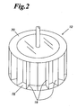
- air separator 10 includes a rotor 12 centrally positioned inside a corresponding rotor housing 14 about a vertical axis.
- a rotary shaft 16 extends through the rotor housing 14 and is attached to the rotor 12 along a common concentric vertical axis.
- the rotor 12 is supported within the rotor housing 14, so that it rotates freely within the housing 14 around the vertical, shaft-defined axis.
- the rotor 12 itself is a drum or fan designed to let air and small particles pass vortically inward to the interior of the drum.
- the rotor 12 is typically comprised of vertically extending rotor vanes 18 supported by at least an annular upper vane support 20, and preferably also by a lower annular vane support 22.
- the rotor vanes 18 are mounted between the upper supports 20 and lower supports 22 and are fixed into position.
- the rotor vanes 18 direct air and comminuted material into the interior of the rotor drum 12.
- the rotational velocity of the rotor 12 can be altered to control the size of the particles that are allowed to pass into the rotor 12.
- the rotor housing 14 defines a substantially hollow cylindrical cavity wherein pre-separated material can be acted on by vortical forces created by the rotor and the rotor vanes 18.
- a secondary material feed 24 is located above the rotor 12, preferably concentric with the rotary shaft 16, and extending through the surface of the rotor housing 14.
- Material from the secondary material feed 24 is fed directly to the rotor 12, preferably from a ball mill or other type mill capable of fine-grinding the comminuted material.
- Material from the secondary material feed 24 is of a sufficiently small size and dimension that it will not harm the rotor 12 or the rotor vanes 18 when fed into the rotor housing 14. It is preferable that material entering the secondary material feed 24 is of a size and dimension that would normally be carried by the vortical forces in the rotor housing 14. That is, material from the secondary feed 24 is preferably small enough to be carried by the wind currents inside the rotor housing 14.
- the product duct 26 Situated directly beneath the rotor 12 is the product duct 26. Comminuted material that is fine enough to be drawn into the rotor 12 is conducted into the product duct 26, and out of the air separator 10 through a product exit port 28. The product exit port 28 can then be connected to other machinery for settling the comminuted product from the conveying air.
- the product duct 26 is comprised of two regions, the upper cylindrical portion 30 located proximate to the rotor 12, and the lower frusto-conical portion 32, located distal from the rotor 12. This profile allows for the maintenance of sufficient velocities within the product duct 26.
- the product exit port 28 is provided with a slight vacuum, such that air within the air separator 10 is drawn out through the product exit port 28. This ensures the prompt removal of finely comminuted material from the air separator 10.
- the fine rejects vessel 36 is positioned generally concentrically around the product vessel or duct 26, with the product discharge outlet or exit port 28 extending therethrough. Similar to the product vessel 26, the fine rejects vessel 36 is comprised of an upper cylindrical portion 38, and a lower frusto-conical portion 40. The upper edge of the upper portion 38 is generally coplanar with the intersection of the product vessel 26 and the rotor 12. The plurality of guide vanes 34 are connected to and extend from the top of the upper portion 38 and are also connected to the rotor housing 14.
- Material collected into the fine rejects vessel 36 is directed out of the air separator 10 through discharge outlet or exit 42. Material from the exit 42 can then be redirected to a ball mill grinder for further processing, and eventual reintroduction to the air separator 10 through the secondary material feed 24.
- a final coarse rejects vessel 44 is concentrically located around the fine rejects vessel 36, with both the product exit 28 and the fine rejects exit port 42 extending there through.
- the coarse rejects vessel 44 is comprised of an upper cylindrical portion 46, and a lower frusto-conical portion 48, similar to the fine rejects vessel 36.
- the annularly defined space 52 between the upper portion 38 of the fine rejects vessel 36 and the upper portion 46 of final coarse rejects vessel 44 allow for air flow from that annular space 52 upward through the plurality of guide vanes 34, and into the rotor 12.
- a primary material feed 56 Integrally and tangentially attached to the coarse rejects vessel is a primary material feed 56.
- the primary material feed 56 functions both as an air inlet and for introduction of coarsely comminuted feed material.
- Feed material entering the air separator 10 at the primary material feed 56 is typically material that has been passed through a first stage comminution device, such as a high pressure roll press.
- the feed 56 is a spiral inlet, preferably having a 180° twist. Air entering the separator 10 at the primary material feed 56 creates a flow that can carry fine particles upward into the rotor housing 14 and rotor 12 for segregation between the product vessel 26 and fine rejects vessel 36. Material from the primary material feed 56 that is too heavy for transport into the rotor housing 14 is separated out of the air separator 10 into the coarse rejects vessel 44, and is discharged at the coarse rejects discharge outlet or exit 50, for further comminution.
- the air separator is provided with a plurality of concentric, partially conical vessels.
- a rotor is provided atop the vessels to provide vortical wind currents within the vessels, and segregates feed material into the various vessels based on particle size. Separated feed material is withdrawn from one of a plurality of vessel exit ports for use as a final product. Withdrawn comminuted material can be reintroduced into the air separator at one of a plurality of entrance ports, based on either or both of the size of the particles, and the comminution processes already undergone.
Claims (3)
- Séparateur à air pour la séparation sélective de particules de différentes tailles comprenant :une série de récipients concentriques (26, 36, 44), le séparateur ayant au moins une entrée de matière (56) et trois sorties de décharge de matière (28, 42, 40), chaque sortie étant associée avec l'un desdits récipients ;chacun desdits récipients étant partiellement conique ;un logement supérieur (14) ayant une surface supérieure et une surface intérieure substantiellement cylindrique ;un arbre rotatif (16) s'étendant à travers ladite surface supérieure, concentrique avec ladite surface intérieure ;un rotor (12) concentrique avec ladite surface intérieure, ledit rotor (12) étant fixé audit arbre rotatif (16) ;un premier récipient concentrique (44), ledit premier récipient comprenant une première portion supérieure ayant une entrée d'air (52) alignée tangentiellement, et une première portion inférieure tronconique (48) ayant au moins une première paroi latérale et une première sortie de matière ;un second récipient concentrique (36), disposé à l'intérieur dudit premier récipient concentrique (44), ledit second récipient concentrique comprenant une seconde portion supérieure (38) et une seconde portion inférieure tronconique (40) ayant au moins une seconde paroi latérale et une seconde sortie de matière (42) s'étendant à travers ladite première paroi latérale;un troisième récipient concentrique (26), disposé à l'intérieur dudit premier récipient concentrique (44), ledit troisième récipient concentrique (26) comprenant une troisième sortie de matière (28) s'étendant à travers ladite première paroi latérale et ladite seconde paroi latérale;caractérisé en ce que le séparateur d'air comprend en outre :une seconde alimentation en matière (24) s'étendant à travers ladite surface supérieure pour distribuer des matières non triées à l'intérieur dudit logement supérieur (14) ;ledit troisième récipient concentrique (26) étant disposé positionné substantiellement en dessous dudit rotor (12) ;ladite première alimentation en matière (56) étant connectée à ladite entrée d'air tangentielle (52) ; etdans lequel ladite seconde portion supérieure (38) constitue une barrière entre ladite première portion supérieure (46) et l'intérieur dudit second récipient concentrique (38), et dans lequel un flux d'air est dirigé à partir de ladite entrée d'air (56) sur ladite barrière, traverse ledit rotor (12), et sort par ladite troisième sortie de matière (28).
- Séparateur à air selon la revendication 1, comprenant en outre:une presse à rouleau ;un broyeur, dans lequel la seconde alimentation en matière (24) est disposée pour recevoir de la matière provenant dudit broyeur ;dans lequel la première sortie de matière (50) est disposée pour distribuer de la matière séparée à ladite presse à rouleau;dans lequel la seconde sortie de matière (42) est disposée pour distribuer de la matière séparée audit broyeur ;dans lequel la troisième sortie de matière (28) est disposée pour distribuer un produit fini et dans lequel la première alimentation en matière (24) est disposée pour recevoir de la matière provenant de ladite presse à rouleau.
- Procédé pour trier de la matière broyée destinée à être traitée ultérieurement comprenant ;
fournir un séparateur à air comprenant :un séparateur à air pour la séparation sélective de particules de différentes tailles comprenant :une série de récipients concentriques (26, 36, 44), le séparateur ayant au moins une entrée de matière (56) et trois sorties de décharge de matière (28, 42, 40), chaque sortie étant associée avec l'un desdits récipients ;chacun desdits récipients étant partiellement conique ; un logement supérieur (14) ayant une surface supérieure et une surface intérieure substantiellement cylindrique ;un arbre rotatif (16) s'étendant à travers ladite surface supérieure, concentrique avec ladite surface intérieure ;un rotor (12) concentrique avec ladite surface intérieure, ledit rotor (12) étant fixé audit arbre rotatif (16) ;une seconde alimentation en matière (24) s'étendant à travers ladite surface supérieure pour distribuer des matières non triées à l'intérieur dudit logement supérieur (14) ;un premier récipient concentrique (44), ledit premier récipient comprenant une première portion supérieure ayant une entrée d'air (52) alignée tangentiellement, et une première portion inférieure tronconique (48) ayant au moins une première paroi latérale et une première sortie de matière ;un second récipient concentrique (36), disposé à l'intérieur dudit premier récipient concentrique (44), ledit second récipient concentrique comprenant une seconde portion supérieure (38) et une seconde portion inférieure tronconique (40) ayant au moins une seconde paroi latérale et une seconde sortie de matière (42) s'étendant à travers ladite première paroi latérale;un troisième récipient concentrique (26), disposé à l'intérieur dudit premier récipient concentrique (44), et positionné substantiellement au-dessous dudit rotor (12), ledit troisième récipient concentrique (26) comprenant une troisième sortie de matière (28) s'étendant à travers ladite première paroi latérale et ladite seconde paroi latérale;ladite première alimentation en matière (56) étant connectée à ladite entrée d'air tangentielle (52) ; et dans lequel ladite seconde portion supérieure (38) constitue une barrière entre ladite première portion supérieure (46) et l'intérieur dudit second récipient concentrique (38), et dans lequel un flux d'air est dirigé à partir de ladite entrée d'air (56) sur ladite barrière, traverse ledit rotor (12), et sort par ladite troisième sortie de matière (28) ;et fournir: une presse à rouleau ;un broyeur, dans lequel la seconde alimentation en matière (24) est disposée pour recevoir de la matière provenant dudit broyeur ;dans lequel la première sortie de matière (50) est disposée pour distribuer de la matière séparée à ladite presse à rouleau ;dans lequel la seconde sortie de matière (42) est disposée pour distribuer de la matière séparée audit broyeur ;dans lequel la troisième sortie de matière (28) est disposée pour distribuer un produit fini et dans lequel la première alimentation en matière (24) est disposée pour recevoir de la matière provenant de ladite presse à rouleau ;et recevoir une première matière de la presse à rouleau et l'introduire dans la première alimentation en matière (56) ;recevoir une seconde matière provenant d'un broyeur et l'introduire dans ladite seconde alimentation en matière (24) ;trier ladite première matière et ladite seconde matière pour distribution soit à partir de ladite première sortie de matière (50), soit à partir de ladite troisième sortie de matière (28) et diriger un flux d'air depuis une entrée d'air sur ladite barrière à travers ledit rotor (12) et en sortant de ladite troisième sortie de matière (28).
Applications Claiming Priority (2)
| Application Number | Priority Date | Filing Date | Title |
|---|---|---|---|
| US87961807P | 2007-01-10 | 2007-01-10 | |
| PCT/US2008/000356 WO2008086026A1 (fr) | 2007-01-10 | 2008-01-10 | Séparateur à air pour matériaux broyés |
Publications (4)
| Publication Number | Publication Date |
|---|---|
| EP2125229A1 EP2125229A1 (fr) | 2009-12-02 |
| EP2125229A4 EP2125229A4 (fr) | 2013-03-27 |
| EP2125229B1 true EP2125229B1 (fr) | 2014-02-26 |
| EP2125229B2 EP2125229B2 (fr) | 2021-01-13 |
Family
ID=39609015
Family Applications (1)
| Application Number | Title | Priority Date | Filing Date |
|---|---|---|---|
| EP08705553.9A Not-in-force EP2125229B2 (fr) | 2007-01-10 | 2008-01-10 | Séparateur à air pour matériaux broyés |
Country Status (3)
| Country | Link |
|---|---|
| EP (1) | EP2125229B2 (fr) |
| DK (1) | DK2125229T4 (fr) |
| WO (1) | WO2008086026A1 (fr) |
Cited By (1)
| Publication number | Priority date | Publication date | Assignee | Title |
|---|---|---|---|---|
| DE102016203420A1 (de) | 2016-03-02 | 2017-09-07 | Thyssenkrupp Ag | Sichter zum Sichten eines Materialstroms |
Families Citing this family (1)
| Publication number | Priority date | Publication date | Assignee | Title |
|---|---|---|---|---|
| DE102017203812A1 (de) * | 2017-03-08 | 2018-09-13 | Thyssenkrupp Ag | Sichteinrichtung und Verfahren zum Sichten eines Materialstroms |
Family Cites Families (9)
| Publication number | Priority date | Publication date | Assignee | Title |
|---|---|---|---|---|
| US1735479A (en) * | 1928-02-04 | 1929-11-12 | Sturtevant Mill Co | Air separator |
| DE908096C (de) * | 1951-04-25 | 1954-04-01 | Babcock & Wilcox Dampfkessel W | Windsichter |
| US3490702A (en) * | 1966-10-24 | 1970-01-20 | D Ore Mills Inc | Method of accelerating production of portland cement and similar material |
| DE4005323A1 (de) † | 1990-02-20 | 1991-08-22 | Krupp Polysius Ag | Verfahren und mahlanlage zur zweistufigen zerkleinerung von sproedem mahlgut |
| DE4112018A1 (de) * | 1990-06-08 | 1991-12-12 | Kloeckner Humboldt Deutz Ag | Sichter |
| DK167054B1 (da) * | 1990-11-26 | 1993-08-23 | Smidth & Co As F L | Dobbeltseparator til udskillelse af partikelformet materiale |
| DE4040890C2 (de) * | 1990-12-20 | 1995-03-23 | Krupp Foerdertechnik Gmbh | Windsichter |
| DE4224704C2 (de) † | 1992-07-25 | 2002-01-31 | Kloeckner Humboldt Wedag | Verfahren und Anlage zur Zerkleinerung von Mahlgut |
| DE102004027128A1 (de) † | 2004-06-03 | 2005-12-22 | Polysius Ag | Vorrichtung zum Sichten von körnigem Gut in wenigstens drei Kornfraktionen |
-
2008
- 2008-01-10 EP EP08705553.9A patent/EP2125229B2/fr not_active Not-in-force
- 2008-01-10 WO PCT/US2008/000356 patent/WO2008086026A1/fr active Application Filing
- 2008-01-10 DK DK08705553.9T patent/DK2125229T4/da active
Cited By (2)
| Publication number | Priority date | Publication date | Assignee | Title |
|---|---|---|---|---|
| DE102016203420A1 (de) | 2016-03-02 | 2017-09-07 | Thyssenkrupp Ag | Sichter zum Sichten eines Materialstroms |
| WO2017148882A1 (fr) | 2016-03-02 | 2017-09-08 | Thyssenkrupp Industrial Solutions Ag | Séparateur pour séparer un flux de matériaux |
Also Published As
| Publication number | Publication date |
|---|---|
| EP2125229A1 (fr) | 2009-12-02 |
| WO2008086026A1 (fr) | 2008-07-17 |
| EP2125229A4 (fr) | 2013-03-27 |
| EP2125229B2 (fr) | 2021-01-13 |
| DK2125229T3 (da) | 2014-05-19 |
| DK2125229T4 (da) | 2021-02-22 |
Similar Documents
| Publication | Publication Date | Title |
|---|---|---|
| US4869786A (en) | Air classifying process and air classifier | |
| EP0204412B2 (fr) | Séparateur pour le tirage de particules de matière | |
| US7108138B2 (en) | Material classifier | |
| KR101795835B1 (ko) | 분체 분급장치 | |
| CN201168700Y (zh) | 一种离心式气流分级器 | |
| CA1212366A (fr) | Broyeur-crible vertical | |
| US6902126B2 (en) | Hybrid turbine classifier | |
| US10926270B2 (en) | Method for operating a multi-cyclone for the separation of fine and very fine grain as well as a multi-cyclone | |
| JPH05245442A (ja) | 分級機 | |
| EP0159766B1 (fr) | Appareil pour le tri de particules | |
| EP3302809B1 (fr) | Broyeur à rouleaux vertical | |
| EP2125229B1 (fr) | Séparateur à air pour matériaux broyés | |
| US7854406B2 (en) | Air separator for comminuted materials | |
| DK2718028T3 (en) | DYNAMIC SEPARATOR FOR POWDER-MATERIALS AND PROCEDURE FOR SIMILAR SEPARATION | |
| US4776950A (en) | Classifier | |
| JP3570265B2 (ja) | 粉砕装置 | |
| JP4747130B2 (ja) | 粉体分級装置 | |
| JP2018202303A (ja) | 粉体の分級装置及び分級システム | |
| JPH04135654A (ja) | セメントクリンカの粉砕装置 | |
| JP3832095B2 (ja) | 粉砕装置 | |
| JPS6211902B2 (fr) | ||
| JPH04210257A (ja) | 粉砕システム | |
| JP5075584B2 (ja) | 粉砕処理装置 | |
| JP2018176098A (ja) | 廃棄物選別機及びその選別方法 | |
| JP3091289B2 (ja) | 衝突式気流粉砕装置 |
Legal Events
| Date | Code | Title | Description |
|---|---|---|---|
| PUAI | Public reference made under article 153(3) epc to a published international application that has entered the european phase |
Free format text: ORIGINAL CODE: 0009012 |
|
| 17P | Request for examination filed |
Effective date: 20090810 |
|
| AK | Designated contracting states |
Kind code of ref document: A1 Designated state(s): AT BE BG CH CY CZ DE DK EE ES FI FR GB GR HR HU IE IS IT LI LT LU LV MC MT NL NO PL PT RO SE SI SK TR |
|
| DAX | Request for extension of the european patent (deleted) | ||
| A4 | Supplementary search report drawn up and despatched |
Effective date: 20130221 |
|
| RIC1 | Information provided on ipc code assigned before grant |
Ipc: B07B 9/02 20060101ALI20130215BHEP Ipc: B02C 17/06 20060101AFI20130215BHEP Ipc: B07B 7/086 20060101ALI20130215BHEP Ipc: B07B 4/02 20060101ALI20130215BHEP Ipc: B02C 23/08 20060101ALI20130215BHEP Ipc: B07B 7/083 20060101ALI20130215BHEP |
|
| GRAP | Despatch of communication of intention to grant a patent |
Free format text: ORIGINAL CODE: EPIDOSNIGR1 |
|
| INTG | Intention to grant announced |
Effective date: 20130910 |
|
| GRAS | Grant fee paid |
Free format text: ORIGINAL CODE: EPIDOSNIGR3 |
|
| RAP1 | Party data changed (applicant data changed or rights of an application transferred) |
Owner name: MASCHINENFABRIK KOEPPERN GMBH & CO. KG |
|
| GRAA | (expected) grant |
Free format text: ORIGINAL CODE: 0009210 |
|
| AK | Designated contracting states |
Kind code of ref document: B1 Designated state(s): AT BE BG CH CY CZ DE DK EE ES FI FR GB GR HR HU IE IS IT LI LT LU LV MC MT NL NO PL PT RO SE SI SK TR |
|
| REG | Reference to a national code |
Ref country code: GB Ref legal event code: FG4D |
|
| REG | Reference to a national code |
Ref country code: CH Ref legal event code: EP |
|
| REG | Reference to a national code |
Ref country code: AT Ref legal event code: REF Ref document number: 653232 Country of ref document: AT Kind code of ref document: T Effective date: 20140315 |
|
| REG | Reference to a national code |
Ref country code: IE Ref legal event code: FG4D |
|
| REG | Reference to a national code |
Ref country code: DE Ref legal event code: R096 Ref document number: 602008030426 Country of ref document: DE Effective date: 20140410 |
|
| REG | Reference to a national code |
Ref country code: DK Ref legal event code: T3 Effective date: 20140515 |
|
| REG | Reference to a national code |
Ref country code: NL Ref legal event code: VDEP Effective date: 20140226 |
|
| REG | Reference to a national code |
Ref country code: LT Ref legal event code: MG4D |
|
| PG25 | Lapsed in a contracting state [announced via postgrant information from national office to epo] |
Ref country code: IS Free format text: LAPSE BECAUSE OF FAILURE TO SUBMIT A TRANSLATION OF THE DESCRIPTION OR TO PAY THE FEE WITHIN THE PRESCRIBED TIME-LIMIT Effective date: 20140626 Ref country code: NO Free format text: LAPSE BECAUSE OF FAILURE TO SUBMIT A TRANSLATION OF THE DESCRIPTION OR TO PAY THE FEE WITHIN THE PRESCRIBED TIME-LIMIT Effective date: 20140526 Ref country code: LT Free format text: LAPSE BECAUSE OF FAILURE TO SUBMIT A TRANSLATION OF THE DESCRIPTION OR TO PAY THE FEE WITHIN THE PRESCRIBED TIME-LIMIT Effective date: 20140226 |
|
| PG25 | Lapsed in a contracting state [announced via postgrant information from national office to epo] |
Ref country code: CY Free format text: LAPSE BECAUSE OF FAILURE TO SUBMIT A TRANSLATION OF THE DESCRIPTION OR TO PAY THE FEE WITHIN THE PRESCRIBED TIME-LIMIT Effective date: 20140226 Ref country code: PT Free format text: LAPSE BECAUSE OF FAILURE TO SUBMIT A TRANSLATION OF THE DESCRIPTION OR TO PAY THE FEE WITHIN THE PRESCRIBED TIME-LIMIT Effective date: 20140626 Ref country code: SE Free format text: LAPSE BECAUSE OF FAILURE TO SUBMIT A TRANSLATION OF THE DESCRIPTION OR TO PAY THE FEE WITHIN THE PRESCRIBED TIME-LIMIT Effective date: 20140226 Ref country code: NL Free format text: LAPSE BECAUSE OF FAILURE TO SUBMIT A TRANSLATION OF THE DESCRIPTION OR TO PAY THE FEE WITHIN THE PRESCRIBED TIME-LIMIT Effective date: 20140226 |
|
| PG25 | Lapsed in a contracting state [announced via postgrant information from national office to epo] |
Ref country code: LV Free format text: LAPSE BECAUSE OF FAILURE TO SUBMIT A TRANSLATION OF THE DESCRIPTION OR TO PAY THE FEE WITHIN THE PRESCRIBED TIME-LIMIT Effective date: 20140226 Ref country code: HR Free format text: LAPSE BECAUSE OF FAILURE TO SUBMIT A TRANSLATION OF THE DESCRIPTION OR TO PAY THE FEE WITHIN THE PRESCRIBED TIME-LIMIT Effective date: 20140226 |
|
| PG25 | Lapsed in a contracting state [announced via postgrant information from national office to epo] |
Ref country code: RO Free format text: LAPSE BECAUSE OF FAILURE TO SUBMIT A TRANSLATION OF THE DESCRIPTION OR TO PAY THE FEE WITHIN THE PRESCRIBED TIME-LIMIT Effective date: 20140226 Ref country code: EE Free format text: LAPSE BECAUSE OF FAILURE TO SUBMIT A TRANSLATION OF THE DESCRIPTION OR TO PAY THE FEE WITHIN THE PRESCRIBED TIME-LIMIT Effective date: 20140226 |
|
| REG | Reference to a national code |
Ref country code: DE Ref legal event code: R026 Ref document number: 602008030426 Country of ref document: DE |
|
| PG25 | Lapsed in a contracting state [announced via postgrant information from national office to epo] |
Ref country code: SK Free format text: LAPSE BECAUSE OF FAILURE TO SUBMIT A TRANSLATION OF THE DESCRIPTION OR TO PAY THE FEE WITHIN THE PRESCRIBED TIME-LIMIT Effective date: 20140226 Ref country code: ES Free format text: LAPSE BECAUSE OF FAILURE TO SUBMIT A TRANSLATION OF THE DESCRIPTION OR TO PAY THE FEE WITHIN THE PRESCRIBED TIME-LIMIT Effective date: 20140226 Ref country code: PL Free format text: LAPSE BECAUSE OF FAILURE TO SUBMIT A TRANSLATION OF THE DESCRIPTION OR TO PAY THE FEE WITHIN THE PRESCRIBED TIME-LIMIT Effective date: 20140226 |
|
| PLBI | Opposition filed |
Free format text: ORIGINAL CODE: 0009260 |
|
| 26 | Opposition filed |
Opponent name: THYSSENKRUPP INDUSTRIAL SOLUTIONS AG Effective date: 20141126 |
|
| PLAX | Notice of opposition and request to file observation + time limit sent |
Free format text: ORIGINAL CODE: EPIDOSNOBS2 |
|
| REG | Reference to a national code |
Ref country code: DE Ref legal event code: R026 Ref document number: 602008030426 Country of ref document: DE Effective date: 20141126 |
|
| PG25 | Lapsed in a contracting state [announced via postgrant information from national office to epo] |
Ref country code: IT Free format text: LAPSE BECAUSE OF FAILURE TO SUBMIT A TRANSLATION OF THE DESCRIPTION OR TO PAY THE FEE WITHIN THE PRESCRIBED TIME-LIMIT Effective date: 20140226 |
|
| PG25 | Lapsed in a contracting state [announced via postgrant information from national office to epo] |
Ref country code: SI Free format text: LAPSE BECAUSE OF FAILURE TO SUBMIT A TRANSLATION OF THE DESCRIPTION OR TO PAY THE FEE WITHIN THE PRESCRIBED TIME-LIMIT Effective date: 20140226 |
|
| PLBB | Reply of patent proprietor to notice(s) of opposition received |
Free format text: ORIGINAL CODE: EPIDOSNOBS3 |
|
| REG | Reference to a national code |
Ref country code: CH Ref legal event code: PL |
|
| PG25 | Lapsed in a contracting state [announced via postgrant information from national office to epo] |
Ref country code: LU Free format text: LAPSE BECAUSE OF FAILURE TO SUBMIT A TRANSLATION OF THE DESCRIPTION OR TO PAY THE FEE WITHIN THE PRESCRIBED TIME-LIMIT Effective date: 20150110 |
|
| GBPC | Gb: european patent ceased through non-payment of renewal fee |
Effective date: 20150110 |
|
| PG25 | Lapsed in a contracting state [announced via postgrant information from national office to epo] |
Ref country code: MC Free format text: LAPSE BECAUSE OF FAILURE TO SUBMIT A TRANSLATION OF THE DESCRIPTION OR TO PAY THE FEE WITHIN THE PRESCRIBED TIME-LIMIT Effective date: 20140226 |
|
| PG25 | Lapsed in a contracting state [announced via postgrant information from national office to epo] |
Ref country code: LI Free format text: LAPSE BECAUSE OF NON-PAYMENT OF DUE FEES Effective date: 20150131 Ref country code: CH Free format text: LAPSE BECAUSE OF NON-PAYMENT OF DUE FEES Effective date: 20150131 Ref country code: GB Free format text: LAPSE BECAUSE OF NON-PAYMENT OF DUE FEES Effective date: 20150110 |
|
| REG | Reference to a national code |
Ref country code: IE Ref legal event code: MM4A |
|
| REG | Reference to a national code |
Ref country code: FR Ref legal event code: PLFP Year of fee payment: 9 |
|
| PG25 | Lapsed in a contracting state [announced via postgrant information from national office to epo] |
Ref country code: IE Free format text: LAPSE BECAUSE OF NON-PAYMENT OF DUE FEES Effective date: 20150110 |
|
| APAH | Appeal reference modified |
Free format text: ORIGINAL CODE: EPIDOSCREFNO |
|
| APBM | Appeal reference recorded |
Free format text: ORIGINAL CODE: EPIDOSNREFNO |
|
| APBP | Date of receipt of notice of appeal recorded |
Free format text: ORIGINAL CODE: EPIDOSNNOA2O |
|
| APBM | Appeal reference recorded |
Free format text: ORIGINAL CODE: EPIDOSNREFNO |
|
| APBP | Date of receipt of notice of appeal recorded |
Free format text: ORIGINAL CODE: EPIDOSNNOA2O |
|
| APBQ | Date of receipt of statement of grounds of appeal recorded |
Free format text: ORIGINAL CODE: EPIDOSNNOA3O |
|
| APBQ | Date of receipt of statement of grounds of appeal recorded |
Free format text: ORIGINAL CODE: EPIDOSNNOA3O |
|
| PG25 | Lapsed in a contracting state [announced via postgrant information from national office to epo] |
Ref country code: GR Free format text: LAPSE BECAUSE OF FAILURE TO SUBMIT A TRANSLATION OF THE DESCRIPTION OR TO PAY THE FEE WITHIN THE PRESCRIBED TIME-LIMIT Effective date: 20140527 |
|
| PG25 | Lapsed in a contracting state [announced via postgrant information from national office to epo] |
Ref country code: MT Free format text: LAPSE BECAUSE OF FAILURE TO SUBMIT A TRANSLATION OF THE DESCRIPTION OR TO PAY THE FEE WITHIN THE PRESCRIBED TIME-LIMIT Effective date: 20140226 |
|
| REG | Reference to a national code |
Ref country code: FR Ref legal event code: PLFP Year of fee payment: 10 |
|
| PG25 | Lapsed in a contracting state [announced via postgrant information from national office to epo] |
Ref country code: HU Free format text: LAPSE BECAUSE OF FAILURE TO SUBMIT A TRANSLATION OF THE DESCRIPTION OR TO PAY THE FEE WITHIN THE PRESCRIBED TIME-LIMIT; INVALID AB INITIO Effective date: 20080110 Ref country code: BG Free format text: LAPSE BECAUSE OF FAILURE TO SUBMIT A TRANSLATION OF THE DESCRIPTION OR TO PAY THE FEE WITHIN THE PRESCRIBED TIME-LIMIT Effective date: 20140226 |
|
| PG25 | Lapsed in a contracting state [announced via postgrant information from national office to epo] |
Ref country code: TR Free format text: LAPSE BECAUSE OF FAILURE TO SUBMIT A TRANSLATION OF THE DESCRIPTION OR TO PAY THE FEE WITHIN THE PRESCRIBED TIME-LIMIT Effective date: 20140226 |
|
| REG | Reference to a national code |
Ref country code: FR Ref legal event code: PLFP Year of fee payment: 11 |
|
| PLAB | Opposition data, opponent's data or that of the opponent's representative modified |
Free format text: ORIGINAL CODE: 0009299OPPO |
|
| R26 | Opposition filed (corrected) |
Opponent name: THYSSENKRUPP INDUSTRIAL SOLUTIONS AG Effective date: 20141126 |
|
| APBU | Appeal procedure closed |
Free format text: ORIGINAL CODE: EPIDOSNNOA9O |
|
| PUAH | Patent maintained in amended form |
Free format text: ORIGINAL CODE: 0009272 |
|
| STAA | Information on the status of an ep patent application or granted ep patent |
Free format text: STATUS: PATENT MAINTAINED AS AMENDED |
|
| 27A | Patent maintained in amended form |
Effective date: 20210113 |
|
| AK | Designated contracting states |
Kind code of ref document: B2 Designated state(s): AT BE BG CH CY CZ DE DK EE ES FI FR GB GR HR HU IE IS IT LI LT LU LV MC MT NL NO PL PT RO SE SI SK TR |
|
| REG | Reference to a national code |
Ref country code: DE Ref legal event code: R102 Ref document number: 602008030426 Country of ref document: DE |
|
| REG | Reference to a national code |
Ref country code: DK Ref legal event code: T4 Effective date: 20210219 |
|
| PGFP | Annual fee paid to national office [announced via postgrant information from national office to epo] |
Ref country code: FR Payment date: 20210121 Year of fee payment: 14 Ref country code: CZ Payment date: 20210111 Year of fee payment: 14 |
|
| PGFP | Annual fee paid to national office [announced via postgrant information from national office to epo] |
Ref country code: BE Payment date: 20210120 Year of fee payment: 14 Ref country code: AT Payment date: 20210121 Year of fee payment: 14 |
|
| REG | Reference to a national code |
Ref country code: AT Ref legal event code: MK05 Ref document number: 653232 Country of ref document: AT Kind code of ref document: T Effective date: 20140226 |
|
| PG25 | Lapsed in a contracting state [announced via postgrant information from national office to epo] |
Ref country code: CZ Free format text: LAPSE BECAUSE OF FAILURE TO SUBMIT A TRANSLATION OF THE DESCRIPTION OR TO PAY THE FEE WITHIN THE PRESCRIBED TIME-LIMIT Effective date: 20140226 |
|
| PG25 | Lapsed in a contracting state [announced via postgrant information from national office to epo] |
Ref country code: AT Free format text: LAPSE BECAUSE OF FAILURE TO SUBMIT A TRANSLATION OF THE DESCRIPTION OR TO PAY THE FEE WITHIN THE PRESCRIBED TIME-LIMIT Effective date: 20140226 |
|
| PGFP | Annual fee paid to national office [announced via postgrant information from national office to epo] |
Ref country code: FI Payment date: 20220120 Year of fee payment: 15 Ref country code: DK Payment date: 20220121 Year of fee payment: 15 Ref country code: DE Payment date: 20211216 Year of fee payment: 15 |
|
| REG | Reference to a national code |
Ref country code: BE Ref legal event code: MM Effective date: 20220131 |
|
| PG25 | Lapsed in a contracting state [announced via postgrant information from national office to epo] |
Ref country code: FR Free format text: LAPSE BECAUSE OF NON-PAYMENT OF DUE FEES Effective date: 20220131 Ref country code: BE Free format text: LAPSE BECAUSE OF NON-PAYMENT OF DUE FEES Effective date: 20220131 |
|
| REG | Reference to a national code |
Ref country code: DE Ref legal event code: R119 Ref document number: 602008030426 Country of ref document: DE |
|
| REG | Reference to a national code |
Ref country code: DK Ref legal event code: EBP Effective date: 20230131 |
|
| PG25 | Lapsed in a contracting state [announced via postgrant information from national office to epo] |
Ref country code: FI Free format text: LAPSE BECAUSE OF NON-PAYMENT OF DUE FEES Effective date: 20230110 Ref country code: DE Free format text: LAPSE BECAUSE OF NON-PAYMENT OF DUE FEES Effective date: 20230801 |
|
| PG25 | Lapsed in a contracting state [announced via postgrant information from national office to epo] |
Ref country code: DK Free format text: LAPSE BECAUSE OF NON-PAYMENT OF DUE FEES Effective date: 20230131 |