EP2124505A1 - Radio base station system, control apparatus, and radio apparatus - Google Patents
Radio base station system, control apparatus, and radio apparatus Download PDFInfo
- Publication number
- EP2124505A1 EP2124505A1 EP08172806A EP08172806A EP2124505A1 EP 2124505 A1 EP2124505 A1 EP 2124505A1 EP 08172806 A EP08172806 A EP 08172806A EP 08172806 A EP08172806 A EP 08172806A EP 2124505 A1 EP2124505 A1 EP 2124505A1
- Authority
- EP
- European Patent Office
- Prior art keywords
- radio
- base station
- information
- radio base
- abnormality
- Prior art date
- Legal status (The legal status is an assumption and is not a legal conclusion. Google has not performed a legal analysis and makes no representation as to the accuracy of the status listed.)
- Withdrawn
Links
Images


Classifications
-
- H—ELECTRICITY
- H04—ELECTRIC COMMUNICATION TECHNIQUE
- H04W—WIRELESS COMMUNICATION NETWORKS
- H04W88/00—Devices specially adapted for wireless communication networks, e.g. terminals, base stations or access point devices
- H04W88/08—Access point devices
- H04W88/085—Access point devices with remote components
Definitions
- the embodiment (s) discussed herein relates to a radio base station system, a control apparatus, and a radio apparatus.
- the present invention may be used in a radio base station system in which a plurality of radio apparatuses are connected in serial (cascade-connected) to a control apparatus.
- FIG. 16 is a block diagram illustrating an exemplary configuration of a radio base station system.
- the radio base station system exemplified in FIG. 16 includes a radio network controller (RNC) 100, one or a plurality of radio equipment controllers (RECs) 200, and one or a plurality of pieces of radio equipment (REs) 300.
- RNC radio network controller
- RECs radio equipment controllers
- REs pieces of radio equipment
- the REC 200 is connected to the RNC 100 in a mutually communicable manner by an interface called Iub.
- the REC 200 corresponds to a baseband processing unit which is one function (element) of a radio base station.
- Each RE 300 corresponds to a radio processing unit which is one function of the radio base station.
- the REs 300 can be installed separated from the baseband processing unit and as remote radio apparatuses that provide radio areas (cells or sectors) to remote locations, etc.
- the REs 300 are connected to the REC 200 in a mutually communicable manner using, for example, an electrical or optical serial interface (CPRI interface) called Common Public Radio Interface (CPRI).
- CPRI interface Common Public Radio Interface
- the REC 200 includes modulation and demodulation equipment (MDE) 201 and transmit/receive interfaces (TRX INFs) 202, and each RE 300 includes an amplifying unit 301, a transmit/receive unit (TRX) 302, and a transmit/receive antenna (ANT) 303.
- MDE modulation and demodulation equipment
- TRX INFs transmit/receive interfaces
- ANT transmit/receive antenna
- the MDE 201 modulates, by a predetermined modulation scheme, a downlink (DL) signal received from the RNC 100 and destined for a radio terminal present in a radio area (cell or sector) provided by an RE 300.
- the modulated signal is transferred to a transmit/receive interface 202 corresponding to the RE 300.
- the MDE 201 demodulates, by a predetermined demodulation scheme, an uplink (UL) signal received from a transmit/receive interface 202 and transmits the demodulated signal to the RNC 100.
- the DL and UL signals may include a control signal and user data.
- the DL signal modulated by the MDE 201 is transmitted from the transmit/receive interface 202 to the transmit/receive unit 302 of the RE 300 over a CPRI link.
- the transmit/receive unit 302 performs a predetermined radio transmission process, such as frequency conversion (up-conversion), on the signal received from the REC 200 and thereafter the amplifying unit 301 amplifies the signal to predetermined transmission power and then the signal is transmitted from the transmit/receive antenna 303 serving as a radio (Uu) interface.
- a predetermined radio transmission process such as frequency conversion (up-conversion)
- a radio signal transmitted from a radio terminal present in a radio area provided by an RE 300 and received by the transmit/receive antenna 303 is subjected to low-noise amplification, etc., by the amplifying unit 301, and thereafter the signal is transmitted to the transmit/receive unit 302. Thereafter, the received radio signal is subjected to a predetermined radio reception process, such as frequency conversion (down-conversion), by the transmit/receive unit 302 and then the signal is transmitted to a corresponding transmit/receive interface 202 of the REC 200 by a protocol (CPRI link) on the CPRI interface.
- the signal received by the transmit/receive interface 202 of the REC 200 is transferred to the MDE 201 and demodulated by the MDE 201.
- Patent Document 1 Published Japanese Translation of PCT Application No. 2007-511955
- Patent Document 2 Published Japanese Translation of PCT Application No. 2007-529926
- Patent Document 3 Japanese Patent Application Laid-Open No. 2007-306362
- Non-Patent Document 1 CPRI Specification V3.0 (2006-10-20), "Common Public Radio Interface (CPRI); Interface Specification", [searched on April 25, 2008], Internet ⁇ URL: http://www.cpri.info/downloads/CPRI_v_3_0_2006-10-20.pd f>
- An object of the embodiment is to make it possible to identify individual REs when a plurality of REs are connected in serial (cascade-connected) to an REC.
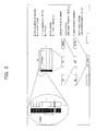
- FIG. 1 is a diagram illustrating a radio base station system according to one embodiment, focusing attention on a CPRI protocol stack architecture.
- the system illustrated in FIG. 1 exemplarily includes an REC (RE control apparatus) 20 connected to an RNC 10 in a mutually communicable manner by an Iub interface; and an RE 30 connected to the REC 20 in a mutually communicable manner.
- REC RE control apparatus
- the terms RE and REC respectively correspond, as previously described, to a remote radio apparatus and a baseband processing unit which are elements of a radio base station, and an interface between the RE and REC is a CPRI link.
- FIG. 2 in the CPRI standard (protocol), as layer 2 (L2), IQ data, vendor-specific information (Vendor Specific), Ethernet (registered trademark), an HDLC (High-level Data Link Control procedure), an L1 inband protocol, etc., are defined (supported). As layer 1 (L1), time division multiplexing and electrical transmission or optical transmission of the L2 signals and information are defined (supported) . Note that the CPRI standard does not provide any specific definition of a layer higher than the L2.
- FIGS. 1 and 2 exemplify that for a higher layer a service access point (SAP) such as a user plane, control and management planes, and synchronization information (SYNC) can be defined (supported).
- SAP service access point
- SYNC synchronization information
- a user plane signal includes a baseband complex signal (IQ data) and vendor-specific information.
- the vendor-specific information is additionally defined information (time slot) and can be freely defined by REC and RE apparatus vendors.
- a control and management (C&M) plane signal includes, for example, vendor-specific information, a signal that requires high real-time performance, L3 protocol data to be transmitted on the HDLC (definition of which is not provided by the CPRI standard), Ethernet data, and L1 inband protocol data (for priority signaling data).
- C&M control and management
- Data including the above-described user plane data, C&M plane data, synchronization information, and vendor-specific information, etc., is time division multiplexed and electrically or optically transmitted.
- the radio frame is a frame to be transmitted and received over a radio area (cell or sector) provided by the RE.
- the first byte of a basic frame is a control word used to transmit C&M plane data and the remaining 15 bytes are data words used to transmit user plane data such as IQ data.
- the control word takes on a sense of a header by organizing 256 bytes of one hyperframe into 4 bytes x 64 subchannels.
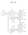
- FIG. 5 is a diagram illustrating a detailed exemplary configuration of a radio base station system according to the above-described embodiment.
- the radio base station system illustrated in FIG. 5 exemplarily includes an RNC 10, an REC 20, a plurality of REs 30-1 to 30-N that make a first RE group, and a plurality of REs 30-1 to 30-M that make a second RE group.
- the RE groups when a distinction is not made between the REs 30-1 to 30-N (or M), they are simply denoted as "RE 30".
- the RNC 10 is connected to one or a plurality of RECs 20 in a mutually communicable manner by an Iub interface.
- the REC (s) 20 is connected to one or a plurality of RE groups in a mutually communicable manner by CPRI.
- the RE groups each have a plurality of REs 30-1 to 30-N (or M) as group members and the group members 30 are connected in serial (tandem) to each other by CPRI.
- This connection form (topology) is also called chain connection or cascade connection.
- communication by the Iub interface is enabled between the RNC 10 and the REC 20 and communication by the CPRI protocol is enabled between the REC 20 and the REs 30 and between the REs 30.
- the RNC 10 can perform control, operations administration maintenance (OAM), etc., on the REC 20 and the REs 30.
- the REC 20 has a function as a baseband processing unit and exemplarily includes modulation and demodulation equipment (MDE) 21 and transmit/receive interfaces (TRX INFs) 22, the number of which corresponds to the number of RE groups.
- Each RE 30 includes an amplifying unit (AMP) 31, a transmit/receive unit (TRX) 32, and a transmit/receive antenna 33.
- AMP amplifying unit
- TRX transmit/receive unit
- antenna 33 a transmit/receive antenna 33.
- the MDE 21 modulates, by a predetermined modulation scheme, a DL signal received from the RNC 10 and destined for a radio terminal present in a radio area (cell or sector) provided by an RE 30.
- the modulated signal is transferred to a transmit/receive interface 22 corresponding to an RE group to which the RE 30 belongs.
- the MDE 21 demodulates, by a predetermined demodulation scheme, an uplink (UL) signal received from a transmit/receive interface 22 and transmits the demodulated signal to the RNC 10.
- the DL and UL signals can include a control signal and user data.
- the DL signal modulated by the MDE 21 is transmitted from the transmit/receive interface 22 to the transmit/receive unit 32 of the RE 30 over a CPRI link.
- a transmit/receive unit 32 performs a predetermined radio transmission process, such as frequency conversion (up-conversion), on a signal received from the REC 20 or an RE 30 of its previous stage, and thereafter, an amplifying unit 31 amplifies the signal to predetermined transmission power and then the signal is transmitted from a transmit/receive antenna 33.
- a radio signal transmitted from a radio terminal present in a radio area provided by an RE 30 and received by a transmit/receive antenna 33 is subjected to low-noise amplification, etc., by an amplifying unit 31, and thereafter the signal is transmitted to a transmit/receive unit 32.
- the received radio signal is subjected to a predetermined radio reception process, such as frequency conversion (down-conversion), by the transmit/receive unit 32 and then the signal is transmitted to a corresponding transmit/receive interface 22 of the REC 20 or a transmit/receive unit 32 of an RE 30 of its previous stage over a CPRI link.
- the signal received by the transmit/receive interface 22 of the REC 20 is transferred to the MDE 21 and demodulated by the MDE 21.
- Each transmit/receive interface 22 is connected, by CPRI, to a transmit/receive unit 32 of the first RE 30-1 belonging to a corresponding RE group and communicates with the transmit/receive unit 32 over a CPRI link.
- a transmit/receive interface 22 transmits a modulated signal received from the MDE 21, to a transmit/receive unit 32 of a corresponding first RE 30-1 over a CPRI link.
- the transmit/receive interface 22 receives, over the CPRI link, a modulated signal transmitted from the transmit/receive unit 32 of the first RE 30-1 and transmits the signal to the MDE 21.
- each transmit/receive interfaces 22 has a function of generating and transmitting/receiving a basic frame and a hyperframe, which are already described, to be transmitted on a CPRI link which is an example of a predetermined communication link.
- the transmit/receive interfaces 22 can generate and transmit/receive control words (vendor-specific information) that are based on the CPRI standard.
- the vendor-specific information is an example of information that can be updated by each RE 30. Part or all of such information is defined as information to be updated by an RE 30 each time passing through the RE 30.
- a transmit/receive interface 22 transmitting the information to a DL CPRI link, the transmit/receive interface 22 can identify REs 30 in a cascade connection, based on an update status of the information having passed through each RE 30.
- each transmit/receive interface 22 has a function as a transmit unit 221 that transmits vendor-specific information (control words), which is an example of the above-described information, to a CPRI link and a function as an identifying unit 222 that performs the above-described identification.
- the function as the identifying unit 222 may be shared between the transmit/receive interfaces 22.
- a transmit/receive unit 32 has a radio communication function and a function of communication by the CPRI protocol (CPRI communication) which is already described.
- the radio communication function enables radio communication via a transmit/receive antenna 33 and the CPRI communication function enables communication with the REC 20 (transmit/receive interface 22) or another RE 30 (transmit/receive unit 32) over a CPRI link.
- each transmit/receive unit 32 has a predetermined radio transmission/reception processing function such as frequency conversion (up-conversion) of a DL signal to be transmitted to an amplifying unit 31 and frequency conversion (down-conversion) of a UL signal received from the amplifying unit 31.
- each transmit/receive unit 32 includes, as illustrated in FIG. 6 , for example, optical modules 321 and 322, a field programmable gate array (FPGA) 323, and a central processing unit (CPU) 324. Furthermore, the FPGA 323 includes, for example, a reset (RST) function unit 3231, a watchdog function unit 3232, a DL function unit 3233, and a UL function unit 3234. Note that the FPGA 323 may be implemented as an individual integrated circuit (an LSI, etc.).
- the optical modules 321 and 322 each are provided for when CPRI link communication is performed by an optical signal, and have a photoelectric conversion function that converts a receive optical signal into an electrical signal and converts a transmit electrical signal into an optical signal.
- the optical module 321 is an optical interface for connection with the REC 20 (transmit/receive interface 22) or an RE 30 (transmit/receive unit 32) of its previous stage
- the optical module 322 is an optical interface for connection with an RE 30 (transmit/receive unit 32) of its subsequent stage.
- the previous stage indicates a side closer to the REC 20 (UL direction) when taking a look at a certain RE 30, and the subsequent stage indicates a side farther from the REC 20 (DL direction).
- the optical module 321 monitors whether there is abnormality in a CPRI link (DL) on the side of the REC 20 or the previous-stage RE 30 and the optical module 322 monitors whether there is abnormality in a CPRI link (UL) on the side of the subsequent-stage RE 30. Whether there is abnormality in the DL CPRI link is reported to the DL function unit 3233 of the FPGA 323 and whether there is abnormality in the UL CPRI link is reported to the UL function unit 3234 of the FPGA 323. That is, the optical modules 321 and 322 are used as an example of a link abnormality detecting unit 320 that detects abnormality in the CPRI link from the previous or subsequent stage. Note that in the present example a state in which a DL/UL optical input cannot be detected is detected as abnormality in the CPRI link.
- the watchdog function unit 3232 periodically monitors normality in the operations (software) of the CPU 324 and the FPGA 323.
- software abnormality is detected, the detection of software abnormality is reported, for example, to the DL function unit 3233. That is, the watchdog function unit 3232 is used as an example of a software abnormality detecting unit that detects software abnormality in the RE 30.
- the DL function unit 3233 receives DL CPRI link data transmitted from the optical module 321 and extracts data (including a control word) and performs data transmission to the optical module 322. These processes can be performed, for example, in a bit unit. At this time, the DL function unit 3233 obtains and manages an RE identifier by referring to vendor-specific information in the control word and sets information indicating that the RE identifier is already obtained to the vendor-specific information (updates the vendor-specific information). When abnormality in the DL CPRI link or the software abnormality is detected, the DL function unit 3233 notifies the REC 20 of the abnormality detection (alarm). For this alarm notification, for example, vendor-specific information in the control word can be used.
- the DL function unit 3233 when abnormality in the DL CPRI link is detected by the optical module 321, the DL function unit 3233 generates a basic frame and a hyperframe, which are already described, and can include alarm notification information in the control word (vendor-specific information).
- the generated frames may be transmitted to the subsequent-stage (DL) side via the optical module 322 or may be transmitted to the previous-stage (UL) side via the UL function unit 3234 and the optical module 321. In either case, alarm notification to the REC 20 is enabled.
- an RE 30 of the subsequent stage can also recognize the CPRI link abnormality occurred on the previous-stage side.
- the UL function unit 3234 receives UL CPRI link data transmitted from the optical module 322 and performs data extraction and data transmission to the optical module 321. These processes can also be performed, for example, in a bit unit. Also, when abnormality in the DL CPRI link is detected by the optical module 321, the UL function unit 3234 generates a basic frame and a hyperframe, which are already described, and can include alarm notification information in the control word (vendor-specific information). The generated frames are transmitted to the previous-stage (REC 20) side via the optical module 321.
- the above-described DL function unit 3233 and UL function unit 3234 can communicate with each other.
- data obtained by the DL function unit 3233 can be transmitted to the UL function unit 3234 and then transmitted to the UL CPRI link. Therefore, the alarm notification information (vendor-specific information) obtained by the DL function unit 3233, as described above, can be transmitted to the UL CPRI link that goes toward the REC 20, from the UL function unit 3234.
- the function units 3233 and 3234 each function as an example of an identifier obtaining unit 325 that obtains an RE identifier based on control words (vendor-specific information) received from the CPRI link on the previous-stage side and also function as an example of a transferring unit 326 that makes an update according to the obtained RE identifier to the control words (vendor-specific information) and transfers the control words to the CPRI link on the subsequent-stage side.
- the function units 3233 and 3234 each are used as an example of a link/software abnormality notifying unit 327 that notifies, when the above-described CPRI link abnormality or software abnormality is detected, the REC 20 of the abnormality (alarm).
- the function of the notifying unit 327 can also be provided in the FPGA 323 as individual functions of link abnormality notification and software abnormality notification.
- the reset function unit 3231 resets (restarts) the CPU 324 and the FPGA 323 when data extracted by the DL function unit 3233 is a reset instruction.
- the reset instruction is issued when the REC 20 receives the above-described software abnormality alarm (ALM) notification.
- ALM software abnormality alarm
- This reset instruction can also use, for example, vendor-specific information in the control word.
- the REC 20 (transmit/receive interface 22) additionally has a function as a software reset control unit 224 (see FIG. 5 ) that transmits, when receiving notification about software abnormality, software reset information destined for an RE 30 identified by the RE identifier to the CPRI link.
- an amplifying unit 31 of each RE 30, for example, amplifies a DL radio signal received from a transmit/receive unit 32 to predetermined transmission power and the signal is transmitted from a transmit/receive antenna 33 to a radio area, and also performs a low-noise amplification on a radio signal received by the transmit/receive antenna 33 and transmits the signal to the transmit/receive unit 32.
- Each transmit/receive antenna 33 is a radio (Uu) interface that transmits a DL radio signal to a radio area and also receives a UL radio signal transmitted from the radio area.
- Uu radio
- an REC 20 recognizes the individual REs 30 (the number of REs, etc.) that are cascade-connected to the REC 20. Each RE 30 recognizes which location in the cascade connection the RE 30 is at (what number the RE 30 is from the REC 20). After these recognitions are made possible, with the individual REs 30 being identified, the REC 20 can receive information notification, such as alarm notification, from the individual REs 30, or can perform control, such as a reset instruction, on the individual REs 30.
- information notification such as alarm notification
- control such as a reset instruction
- control words vendor-specific information
- ALM DL alarm
- S-ALM software alarm
- the definitions (assignments) exemplified in table 1 can be held and managed by, for example, the transmit/receive interface 22, and in each RE 30, the definitions (assignments) can be held and managed by, for example, an FPGA 323 (DL function unit 3233).
- RE identifier, alarm information, and reset instruction fields are assigned for each RE 30 in one byte unit, such assignment is merely an example; the assignment may be performed in a unit of fewer or more bits. For example, it is also possible to assign RE identifier, alarm information, and reset instruction fields for each RE 30 in one bit unit.
- the assignment unit By making the assignment unit smaller, a larger number of assignments to the REs 30 are enabled. On the other hand, by making the assignment unit larger, the error immunity of CPRI communication (assignment of an RE identifier, alarm notification, and reset control) can be improved. In RE identifier assignment, information that is incremented each time each RE 30 obtains an identifier can also be used.
- the REC 20 when the REC 20 (transmit/receive interface 22) recognizes each RE 30 (assigns an RE identifier), the REC 20 (transmit/receive interface 22) can use, as an example, a method such as that illustrated below.
- the REC 20 transmits control words in which all of the RE#i identifiers for eight REs are set to a "not assigned" state (e.g., all "0"), to an RE 30-1 over a DL CPRI link.
- this transmission is performed after synchronization (frame synchronization) of optical links (DL and UL CPRI links) by the optical modules 321 and 322 is established in each RE 30.
- the synchronization establishment is performed using synchronization information (SYNC) which is already described (process 1011 in FIG. 9 ).
- the DL and UL CPRI links pass through each RE 30.
- the REC 20 can receive the information transmitted to the DL CPRI link, over the UL CPRI link.
- Each RE 30 refers to vendor-specific information (RE#1 to #8 identifier fields) in the control words received from the DL CPRI link to check whether there is an identifier field with all "0" (process 1012 in FIG. 9 and process 1041 in FIG. 14 ). If there is an identifier field with all "0", then the RE#i identifier indicates a "not assigned” state and thus the RE 30 can be assigned with the RE#i identifier (RE number). In the example of FIG. 8 , since the RE 30-1 is the first RE, an RE#1 identifier field is supposed to be all "0".
- the RE 30-1 (DL function unit 3233) obtains 1 as its RE identifier (RE number) and recognizes and manages the RE identifier (process 1042 in FIG. 14 ). At this time, the RE 30-1 (DL function unit 3233) changes the value of the RE#1 identifier field from the "not assigned" state (all "0") to an "assigned” state (e.g., all "1") and then transmits the control words to an RE 30-2 of its subsequent stage (process 1013 in FIG. 9 and process 1042 in FIG. 14 ).
- an RE 30 (DL function unit 3233) leaves the RE#i identifier field with all "1" as it is and sequentially checks the rest of RE#2 to #8 identifier fields to see whether there is one with a "not assigned” state (all "0") (processes 1014 and 1017 in FIG. 9 and process 1043 in FIG. 14 ).
- each RE 30 (DL function unit 3233) checks the setting states of the RE#i identifier fields and is assigned with an RE#i identifier with all "0", and changes an RE#i identifier field whose identifier has been assigned to the RE 30, to all "1" and then transmits the control words to an RE 30 of its subsequent stage.
- the RE 30-8 since the RE 30-8 is the last one in the cascade connection, UL and DL CPRI communications for a subsequent-stage RE are terminated by an optical module 322 thereof.
- the DL function unit 3233 of the RE 30-8 transmits DL CPRI link data to a UL function unit 3234 and the data is transmitted back (fed back) to the UL CPRI link from the UL function unit 3234.
- the RE 30-8 transmits back the control words (vendor-specific information) set to the RE#1 to RE#8 identifiers (all "1"), as they are to the UL CPRI link.
- the RE 30-8 (UL function unit 3234) is in a state of abnormality in the UL CPRI link from a subsequent-stage RE 30, the RE 30-8 (UL function unit 3234) may set UL-ALM information in the above-described table 1 corresponding to the RE#8 identifier to all "1" (from an "abnormal" route of process 1044 in FIG. 14 to process 1046).
- the REC 20 can confirm that the RE 30-8 is the last RE in the cascade connection. Note that the UL function units 3234 of those REs 30 other than the last RE 30-8 do not check other RE#i identifiers when the UL CPRI link from their respective subsequent-stage REs 30 is normal (from "normal" route of process 1044 in FIG. 14 to process 1045).
- each RE 30 (UL function unit 3234) transmits (passes through) RE#i identifier fields in control words received thereby, as they are to the side of the REC 20 (process 1020 in FIG. 9 ).
- the REC 20 can recognize (identify) that the eight REs 30 are cascade-connected to each other and manage the REs 30. Also, the REC 20 and each RE 30 can recognize and manage which location (what number) in the cascade connection each RE 30 is at.
- the REC 20 can again recognize the number of REs 30 and the locations of the REs 30 by the above-described CPRI communication. Namely, while existing REs 30 continue communication with the REC 20, communication between the REC 20 and an added or removed RE 30 can be selectively established or disconnected.
- the REC 20 (transmit/receive interface 22) can individually perform DL and UL CPRI communication with the REs 30. For example, by UL CPRI communication, each RE 30 can individually notify the REC 20 of abnormality in the UL/DL CPRI link or abnormality in software of the RE 30.
- the REC 20 can identify between which REs 30 the abnormality has occurred in the CPRI link or can identify which RE 30 the software abnormality has occurred in. Also, the REC 20 can individually reset, by DL CPRI communication, an RE 30 where the software abnormality has occurred.
- the REC 20 (transmit/receive interface unit 22) additionally has a function as a control unit 223 (see FIG. 5 ) that performs, under the identification, control of individual OAM on each RE 30, using the CPRI link.
- the functions of the already-described respective units 221 to 224 exemplified in FIG. 5 may be included in the REC 20 as functions of individual control units.
- the OAM indicates inclusion of any one of operations, administration, and maintenance or a combination of two or more thereof and thus does not indicate that all of operations, administration, and maintenance are required. Also, it is not intended to exclude inclusion of a process other than these three.
- alarm notification includes one or both of the case in which abnormality occurs in the DL/UL CPRI link and the case in which software abnormality in an RE 30 occurs.
- each RE 30 can recognize and manage what number in the cascade connection the RE 30 is connected.
- part of vendor-specific information in CPRI control words is defined (assigned) as alarm (ALM) information fields for the respective REs 30, as exemplified in the above-described table 1.
- the RE 30 where the abnormality has occurred changes a corresponding ALM information field in the UL control words from a state indicating non-occurrence of abnormality (all "0") to a state indicating occurrence of abnormality (all "1") and then transmits the control words to the side of the REC 20. Accordingly, by the REC 20 receiving the UL control words, the REC 20 can recognize in which location in the cascade connection the CPRI link abnormality has occurred or in which RE 30 the software abnormality has occurred.
- the REC 20 transmits control words in which the DL/UL-ALM information (fields) for eight REs are set to a state of non-occurrence of abnormality (e.g., all "0"), to the RE 30-1 over the DL CPRI link (process 1021 in FIG. 11 ).
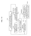
- Each RE 30 (DL function unit 3233) monitors normality of the DL CPRI link between the RE 30 and an RE 30 of its previous stage (process 1022 in FIG. 11 and process 1051 in FIG. 15 ). If normal, then each RE 30 (DL function unit 3233) transmits the control words received over the DL CPRI link to an RE 30 of its subsequent stage without performing any operation on the DL/UL-ALM information in the control words (process 1023 in FIG. 11 and process 1053 in FIG. 15 ).
- the DL function unit 3233 changes DL/UL-ALM information corresponding to an RE#i identifier of the RE 30 to an abnormality occurrence state (e.g., all "1") and then transmits the control words to the RE 30 of its subsequent stage (process 1024 in FIG. 11 and process 1052 in FIG. 15 ).
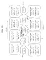
- FIG. 10 exemplifies the case in which abnormality has occurred in the DL CPRI link between the RE 30-1 and the RE 30-2.
- the RE 30-2 detects the abnormality and thus changes DL-ALM information of RE#2 to all "1" and then transmits the control words to the RE 30-3 of its subsequent stage.
- the RE 30-8 (DL function unit 3233) transfers the control words (vendor-specific information) to a UL function unit 3234 and the control words (vendor-specific information) are transmitted back to the UL CPRI link.
- the RE 30-8 since the RE 30-8 does not have an RE 30 of its subsequent stage, the RE 30-8 is in a state of UL CPRI link abnormality. Therefore, the RE 30-8 (UL function unit 3224) changes UL-ALM information corresponding to an RE#8 identifier of the RE 30-8 to all "1" and then transmits the control words to the RE 30-7 of its previous stage (process 1025 in FIG.
- each of the REs 30-7 to 30-1 transmits the control words (UL-ALM information) received from an RE 30 of its subsequent stage as they are to an RE 30 of its previous stage or the REC 20 without performing any operation on the control words (UL-ALM information) (process 1026 in FIG. 11 ). If abnormality has occurred in the UL CPRI link, then the UL function unit 3234 changes UL-ALM information corresponding to an RE#i identifier of the RE 30 to all "1" and then transmits the control words to the RE 30 of its previous stage or the REC 20.
- the REC 20 (transmit/receive interface 22) can recognize whether there is abnormality in the DL/UL CPRI link, by referring to the respective pieces of DL/UL-ALM information in the control words received from the UL CPRI link.
- the REC 20 can determine that abnormality has occurred in the DL CPRI link between the RE 30-1 and RE 30-2.
- the REC 20 e.g., the transmit/receive interface 22
- the REC 20 can confirm, together with RE#8 identifier assignment information which is already described, that the RE 30-8 is the last RE.
- the REC 20 transmits control words in which the RE#i software ALM information (fields) for eight REs are set to a state of non-occurrence of abnormality (e.g., all "0"), to the RE 30-1 over the DL CPRI link (process 1031 in FIG. 13 ).
- Each RE 30 periodically monitors, by its watchdog function unit 3232, whether there is software abnormality (process 1032 in FIG. 13 and process 1051 in FIG. 15 ). If software abnormality is not detected, then the RE 30 (DL function unit 3233) transmits the control words (RE#i software ALM information) received over the DL CPRI link, as they are to an RE 30 of its subsequent stage without performing any operation on the control words (RE#i software ALM information) (process 1033 in FIG. 13 and process 1053 in FIG. 15 ).
- the RE 30 changes RE#i software ALM information corresponding to an RE#i identifier of the RE 30 to an abnormality occurrence state (e.g., all "1") and then transmits the control words to an RE 30 of its subsequent stage (process 1034 in FIG. 13 and process 1052 in FIG. 15 ).
- FIG. 12 exemplifies the case in which software abnormality has occurred in the RE 30-2.
- the RE 30-2 changes RE#2 software ALM information to all "1" and then transmits the control words to the RE 30-3 of its subsequent stage.
- the RE 30-8 Since the last-stage of RE 30-8 (DL function unit 3233) does not have an RE 30 of its subsequent stage, the RE 30-8 transfers the control words (vendor-specific information) to the UL function unit 3234 and the control words (vendor-specific information) are transmitted back to the UL CPRI link (from an "abnormal" route of process 1054 in FIG. 15 to process 1055). Note that those REs 30 other than the last RE 30-8 thereafter continue to monitor by the respective watchdog function units 3221 whether there is software abnormality, if there is no abnormality in the UL CPRI link ("normal" route of process 1054 in FIG. 15 ).
- each of the REs 30-7 to 30-1 (UL function units 3234) transmits the control words (software ALM information) received from an RE 30 of its subsequent stage, as they are to an RE 30 of its previous stage or the REC 20 (processes 1035 and 1036 in FIG. 13 ).
- the REC 20 (transmit/receive interface 22) can recognize which RE 30 software abnormality has occurred in, by referring to the respective pieces of RE#i software ALM information in the control words received from the UL CPRI link. In the case of the example of FIG. 12 , since the RE#2 software ALM information is all "1", the REC 20 can determine that software abnormality has occurred in the RE 30-2.
- the REC 20 (e.g., the transmit/receive interface 22) can keep a log of the ALM information or can notify an operator, etc., of the software abnormality. Also, the REC 20 can forcefully reset software (CPU 324 and FPGA 323) of the RE 30-2 where the software abnormality has occurred.
- the REC 20 transmits, over the DL CPRI link, control words in which RST information (field) corresponding to an RE#i identifier of the RE 30 is set to a state indicating a reset instruction (e.g., all "1"), to the RE 30-1.
- Each RE 30 (DL function unit 3233) checks whether RST information corresponding to an RE#i identifier of the RE 30 is set to all "1", by referring to a corresponding RST information field in the control words received from the DL CPRI link.
- the DL function unit 3233 transmits the received control words as they are to an RE 30 of its subsequent stage.
- the DL function unit 3233 provides a reset instruction to a reset function unit 3231. Accordingly, the reset function unit 3231 performs a software reset (restart) of an FPGA 323 and a CPU 324.
- a UL function unit 3234 can notify the REC 20 of the completion of the reset through the UL CPRI link.
- the notification is enabled by, for example, changing the RST information having been set to all "1", to all "0". Accordingly, the REC 20 can check software reset execution states of the individual REs 30.
- the REC 20 can be allowed to recognize between which of a plurality of REs 30 that are cascade-connected to the REC 20 abnormality has occurred in the CPRI link and/or which RE 30 software abnormality has occurred in. Therefore, an operator, etc., can take quick measures to restore operation.
- the REC 20 when the REC 20 recognizes an RE 30 where software abnormality has occurred, the REC 20 can individually perform a software reset on the RE 30. Hence, a workload imposed on an operator, etc., can be reduced.
- connection form between the REC 20 and a plurality of REs 30 is a cascade (chain) connection
- the above-described process can also be applied to other connection forms (topology), e.g., a tree connection (topology) and a ring connection (topology).
Landscapes
- Engineering & Computer Science (AREA)
- Computer Networks & Wireless Communication (AREA)
- Signal Processing (AREA)
- Mobile Radio Communication Systems (AREA)
Applications Claiming Priority (1)
| Application Number | Priority Date | Filing Date | Title |
|---|---|---|---|
| JP2008131890A JP5131026B2 (ja) | 2008-05-20 | 2008-05-20 | 無線基地局システム並びに制御装置及び無線装置 |
Publications (1)
| Publication Number | Publication Date |
|---|---|
| EP2124505A1 true EP2124505A1 (en) | 2009-11-25 |
Family
ID=41139163
Family Applications (1)
| Application Number | Title | Priority Date | Filing Date |
|---|---|---|---|
| EP08172806A Withdrawn EP2124505A1 (en) | 2008-05-20 | 2008-12-23 | Radio base station system, control apparatus, and radio apparatus |
Country Status (4)
| Country | Link |
|---|---|
| US (1) | US8130729B2 (zh) |
| EP (1) | EP2124505A1 (zh) |
| JP (1) | JP5131026B2 (zh) |
| CN (1) | CN101588588B (zh) |
Cited By (1)
| Publication number | Priority date | Publication date | Assignee | Title |
|---|---|---|---|---|
| EP2736303A1 (en) * | 2012-11-27 | 2014-05-28 | Freescale Semiconductor, Inc. | Method and apparatus for resetting at least one node within a CPRI radio base station system |
Families Citing this family (24)
| Publication number | Priority date | Publication date | Assignee | Title |
|---|---|---|---|---|
| US8572432B1 (en) * | 2009-04-02 | 2013-10-29 | Xilinx, Inc. | Method and apparatus for processing an event notification in a concurrent processing system |
| EP2978149B1 (en) * | 2009-07-27 | 2017-09-20 | Huawei Technologies Co., Ltd. | Signal transmission processing method and apparatus and distributed base station |
| CN101695175B (zh) * | 2009-10-28 | 2013-05-08 | 中兴通讯股份有限公司 | 级联设备告警上报方法、系统和设备 |
| JP5193990B2 (ja) * | 2009-12-17 | 2013-05-08 | 株式会社エヌ・ティ・ティ・ドコモ | 中継装置 |
| KR101674209B1 (ko) * | 2010-01-27 | 2016-11-08 | 삼성전자주식회사 | 디지털 장치와 rf 장치간에 이더넷 데이터를 송수신하는 방법 및 그 장치 |
| JP5041035B2 (ja) * | 2010-06-04 | 2012-10-03 | 住友電気工業株式会社 | 無線装置及び無線基地局装置 |
| CN102340368B (zh) * | 2010-07-19 | 2014-07-02 | 中兴通讯股份有限公司 | 一种cpri链路误码监测方法、系统和装置 |
| CN101938768B (zh) | 2010-08-20 | 2012-12-19 | 华为技术有限公司 | 级联rcu链路扫描的方法和电调天线系统 |
| US8649388B2 (en) * | 2010-09-02 | 2014-02-11 | Integrated Device Technology, Inc. | Transmission of multiprotocol data in a distributed antenna system |
| JP5763959B2 (ja) * | 2011-04-08 | 2015-08-12 | 株式会社日立国際電気 | 無線システム |
| CN103580780B (zh) * | 2012-07-23 | 2018-03-09 | 中兴通讯股份有限公司 | 数据传输方法及装置 |
| JP5865817B2 (ja) * | 2012-10-26 | 2016-02-17 | エヌ・ティ・ティ・コムウェア株式会社 | 情報システム、情報装置、情報処理方法及びプログラム |
| FR3007617A1 (fr) * | 2013-06-19 | 2014-12-26 | France Telecom | Dispositifs de fourniture d'informations de service pour une liaison par faisceau microondes |
| US10342032B2 (en) * | 2013-07-04 | 2019-07-02 | Nxp Usa, Inc. | Method and device for streaming control data in a mobile communication system |
| US10334008B2 (en) * | 2013-07-04 | 2019-06-25 | Nxp Usa, Inc. | Method and device for data streaming in a mobile communication system |
| US9031056B2 (en) | 2013-07-10 | 2015-05-12 | Freescale Semiconductor, Inc. | Wireless communication apparatus and method |
| US9647759B2 (en) * | 2013-12-22 | 2017-05-09 | IPLight Ltd. | Efficient mapping of CPRI signals for sending over optical networks |
| US10405290B2 (en) | 2014-05-14 | 2019-09-03 | Telefonaktiebolaget Lm Ericsson (Publ) | Technique to align frame timing of remote cellular radio elements with the data frame timing reference of radio element |
| RU2017113087A (ru) * | 2014-09-19 | 2018-10-19 | Нек Корпорейшн | Беспроводная система управления и способ для отслеживания ошибки беспроводной линии связи |
| JP2016082402A (ja) | 2014-10-16 | 2016-05-16 | 富士通株式会社 | ベースバンド処理装置、無線装置、及び無線通信システム |
| JP6247247B2 (ja) | 2015-04-10 | 2017-12-13 | ファナック株式会社 | 制御システム |
| US9332567B1 (en) | 2015-05-28 | 2016-05-03 | Freescale Semiconductor, Inc. | System for recovering unresponsive common public radio interface (CPRI) nodes |
| US10044471B2 (en) | 2015-09-01 | 2018-08-07 | IPLight Ltd. | Delivering CPRI and ethernet signals over optical networks |
| CN108463959B (zh) | 2015-11-02 | 2020-03-17 | 瑞典爱立信有限公司 | 用于将无线电接口帧定时参考进行对准的方法和设备 |
Citations (5)
| Publication number | Priority date | Publication date | Assignee | Title |
|---|---|---|---|---|
| US20060265519A1 (en) * | 2001-06-28 | 2006-11-23 | Fortinet, Inc. | Identifying nodes in a ring network |
| JP2007511955A (ja) | 2003-11-17 | 2007-05-10 | テレフオンアクチーボラゲット エル エム エリクソン(パブル) | 分散型無線基地局の内部インターフェース上の非依存送信のカプセル化 |
| EP1802048A1 (en) * | 2004-10-12 | 2007-06-27 | Huawei Technologies Co., Ltd. | A method for implementing topology structure automatic discovery in the mpls ring network |
| JP2007529926A (ja) | 2005-01-12 | 2007-10-25 | ▲ホア▼▲ウェイ▼技術有限公司 | 分離型基地局システム、ネットワーク組織化方法、およびベースバンドユニット |
| JP2007306362A (ja) | 2006-05-12 | 2007-11-22 | Hitachi Kokusai Electric Inc | 通信装置 |
Family Cites Families (10)
| Publication number | Priority date | Publication date | Assignee | Title |
|---|---|---|---|---|
| US7460513B2 (en) * | 2003-11-17 | 2008-12-02 | Telefonaktiebolaget Lm Ericsson (Publ) | Encapsulation of diverse protocols over internal interface of distributed radio base station |
| ES2550104T3 (es) * | 2004-10-12 | 2015-11-04 | Telefonaktiebolaget L- M Ericsson (Publ) | Comunicación entre un nodo de control de equipo de radio y múltiples nodos de equipo de radio remotos |
| CN100479399C (zh) | 2004-11-05 | 2009-04-15 | 上海华为技术有限公司 | 级联组网的寻址系统及其方法 |
| KR20070057322A (ko) * | 2005-12-01 | 2007-06-07 | 삼성전자주식회사 | 원격 알에프 장치의 선택적 리셋이 가능한 기지국 장치 및방법 |
| CN101064631A (zh) * | 2006-04-25 | 2007-10-31 | 华为技术有限公司 | 拓扑结构扫描方法和扫描系统 |
| DE102006019475B4 (de) * | 2006-04-26 | 2008-08-28 | Nokia Siemens Networks Gmbh & Co.Kg | Verfahren zur Synchronisation von Baugruppen einer Basisstation |
| KR100766586B1 (ko) * | 2006-08-16 | 2007-10-12 | 포스데이타 주식회사 | 무선통신망의 구성요소 관리 시스템 |
| JP4791320B2 (ja) * | 2006-10-13 | 2011-10-12 | 富士通株式会社 | コモン・パブリック・ラジオ・インタフェース(cpri)のベンダー特有領域を使った回線迂回方式 |
| CN100508663C (zh) * | 2007-01-11 | 2009-07-01 | 华为技术有限公司 | 实现re始端优先接入rec的方法及设备 |
| US8050296B2 (en) * | 2008-03-31 | 2011-11-01 | Telefonaktiebolaget Lm Ericsson (Publ) | Radio equipment (RE)-based synchronization |
-
2008
- 2008-05-20 JP JP2008131890A patent/JP5131026B2/ja not_active Expired - Fee Related
- 2008-12-23 EP EP08172806A patent/EP2124505A1/en not_active Withdrawn
- 2008-12-29 US US12/345,178 patent/US8130729B2/en not_active Expired - Fee Related
-
2009
- 2009-01-22 CN CN2009100059485A patent/CN101588588B/zh not_active Expired - Fee Related
Patent Citations (5)
| Publication number | Priority date | Publication date | Assignee | Title |
|---|---|---|---|---|
| US20060265519A1 (en) * | 2001-06-28 | 2006-11-23 | Fortinet, Inc. | Identifying nodes in a ring network |
| JP2007511955A (ja) | 2003-11-17 | 2007-05-10 | テレフオンアクチーボラゲット エル エム エリクソン(パブル) | 分散型無線基地局の内部インターフェース上の非依存送信のカプセル化 |
| EP1802048A1 (en) * | 2004-10-12 | 2007-06-27 | Huawei Technologies Co., Ltd. | A method for implementing topology structure automatic discovery in the mpls ring network |
| JP2007529926A (ja) | 2005-01-12 | 2007-10-25 | ▲ホア▼▲ウェイ▼技術有限公司 | 分離型基地局システム、ネットワーク組織化方法、およびベースバンドユニット |
| JP2007306362A (ja) | 2006-05-12 | 2007-11-22 | Hitachi Kokusai Electric Inc | 通信装置 |
Non-Patent Citations (2)
| Title |
|---|
| "Common Public Radio Interface (CPRI); Interface Specification", CPRI SPECIFICATION V3.0, 20 October 2006 (2006-10-20), Retrieved from the Internet <URL:http://cpri.info/downloads/CPRI_v_3_0_2006-10-20.pdf> |
| ERICSSON AB ET AL: "Common Public Radio Interface (CPRI); Interface Specification", CPRI SPECIFICATION V3.0,, no. V3.0, 20 October 2006 (2006-10-20), pages 1 - 89, XP002522320, Retrieved from the Internet <URL:http://www.cpri.info/downloads/CPRI_v_3_0_2006-10-20.pdf> [retrieved on 20090331] * |
Cited By (1)
| Publication number | Priority date | Publication date | Assignee | Title |
|---|---|---|---|---|
| EP2736303A1 (en) * | 2012-11-27 | 2014-05-28 | Freescale Semiconductor, Inc. | Method and apparatus for resetting at least one node within a CPRI radio base station system |
Also Published As
| Publication number | Publication date |
|---|---|
| CN101588588A (zh) | 2009-11-25 |
| CN101588588B (zh) | 2012-08-08 |
| US8130729B2 (en) | 2012-03-06 |
| JP5131026B2 (ja) | 2013-01-30 |
| JP2009284066A (ja) | 2009-12-03 |
| US20090291681A1 (en) | 2009-11-26 |
Similar Documents
| Publication | Publication Date | Title |
|---|---|---|
| US8130729B2 (en) | Radio base station system, control apparatus, and radio apparatus | |
| US11290187B2 (en) | RF transport network | |
| US8254987B2 (en) | Method and apparatus for transmitting data between radio equipment and radio equipment controls | |
| US7937110B2 (en) | Distributed base station system and method for networking thereof and base band unit | |
| US8780802B2 (en) | Communication signal multiplexing method, radio communication system, and radio equipment controller | |
| RU2483479C1 (ru) | Способ и устройство для передачи данных | |
| EP2753141B1 (en) | Data interaction system and method thereof | |
| CN109963290B (zh) | 多业务室内覆盖系统及工作方法 | |
| KR102006964B1 (ko) | 무선 통신 시스템 및 무선 라디오 주파수 장치 | |
| WO2016167394A1 (ko) | 분산 안테나 시스템의 노드 유닛 | |
| JP2020518152A (ja) | 高周波5g基地局及び高周波5g基地局の信号処理方法 | |
| CN102498749B (zh) | 包括用于在无线接入网中交换数据的回程装置的方法和装置 | |
| US10979920B2 (en) | Integrated access system with baseband unit and base station network management | |
| EP3242450B1 (en) | Method of summing forward digital signal in distributed antenna system | |
| Waqar et al. | A study of fronthaul networks in CRANs-requirements and recent advancements | |
| US8233933B2 (en) | Mobile communication system | |
| CN108632828B (zh) | 一种区分不同频段核心网的基站及其处理方法 | |
| CN113852880A (zh) | 组网系统以及相关数据传输方法 | |
| JP2013065977A (ja) | 無線基地局システム及び通信制御方法 | |
| CN115529630B (zh) | 复合通信系统及方法 | |
| EP3937398A1 (en) | Communication node and operating method therefor, and distributed antenna system comprising same | |
| JP2012147193A (ja) | 基地局システム | |
| JP6114364B1 (ja) | 光伝送装置及び光伝送方法 | |
| CN116963126A (zh) | 一种业务数据处理方法以及基站设备 |
Legal Events
| Date | Code | Title | Description |
|---|---|---|---|
| PUAI | Public reference made under article 153(3) epc to a published international application that has entered the european phase |
Free format text: ORIGINAL CODE: 0009012 |
|
| AK | Designated contracting states |
Kind code of ref document: A1 Designated state(s): AT BE BG CH CY CZ DE DK EE ES FI FR GB GR HR HU IE IS IT LI LT LU LV MC MT NL NO PL PT RO SE SI SK TR |
|
| AX | Request for extension of the european patent |
Extension state: AL BA MK RS |
|
| 17P | Request for examination filed |
Effective date: 20100519 |
|
| AKX | Designation fees paid |
Designated state(s): DE FR GB |
|
| 17Q | First examination report despatched |
Effective date: 20150204 |
|
| GRAP | Despatch of communication of intention to grant a patent |
Free format text: ORIGINAL CODE: EPIDOSNIGR1 |
|
| INTG | Intention to grant announced |
Effective date: 20171109 |
|
| STAA | Information on the status of an ep patent application or granted ep patent |
Free format text: STATUS: THE APPLICATION IS DEEMED TO BE WITHDRAWN |
|
| 18D | Application deemed to be withdrawn |
Effective date: 20180320 |