EP2124405A2 - Anordnung und Verfahren zur drahtlosen Übertragung von phasenkritischen Signalen bei variabler Längenänderung der Übertragungsstrecke - Google Patents
Anordnung und Verfahren zur drahtlosen Übertragung von phasenkritischen Signalen bei variabler Längenänderung der Übertragungsstrecke Download PDFInfo
- Publication number
- EP2124405A2 EP2124405A2 EP09006642A EP09006642A EP2124405A2 EP 2124405 A2 EP2124405 A2 EP 2124405A2 EP 09006642 A EP09006642 A EP 09006642A EP 09006642 A EP09006642 A EP 09006642A EP 2124405 A2 EP2124405 A2 EP 2124405A2
- Authority
- EP
- European Patent Office
- Prior art keywords
- transmission path
- measuring
- length
- platform
- phase
- Prior art date
- Legal status (The legal status is an assumption and is not a legal conclusion. Google has not performed a legal analysis and makes no representation as to the accuracy of the status listed.)
- Granted
Links
Images
Classifications
-
- H—ELECTRICITY
- H04—ELECTRIC COMMUNICATION TECHNIQUE
- H04L—TRANSMISSION OF DIGITAL INFORMATION, e.g. TELEGRAPHIC COMMUNICATION
- H04L27/00—Modulated-carrier systems
- H04L27/0014—Carrier regulation
-
- H—ELECTRICITY
- H04—ELECTRIC COMMUNICATION TECHNIQUE
- H04L—TRANSMISSION OF DIGITAL INFORMATION, e.g. TELEGRAPHIC COMMUNICATION
- H04L25/00—Baseband systems
- H04L25/02—Details ; arrangements for supplying electrical power along data transmission lines
- H04L25/06—DC level restoring means; Bias distortion correction ; Decision circuits providing symbol by symbol detection
-
- H—ELECTRICITY
- H04—ELECTRIC COMMUNICATION TECHNIQUE
- H04L—TRANSMISSION OF DIGITAL INFORMATION, e.g. TELEGRAPHIC COMMUNICATION
- H04L25/00—Baseband systems
- H04L25/02—Details ; arrangements for supplying electrical power along data transmission lines
- H04L25/10—Compensating for variations in line balance
-
- H—ELECTRICITY
- H04—ELECTRIC COMMUNICATION TECHNIQUE
- H04L—TRANSMISSION OF DIGITAL INFORMATION, e.g. TELEGRAPHIC COMMUNICATION
- H04L27/00—Modulated-carrier systems
- H04L27/0014—Carrier regulation
- H04L2027/0044—Control loops for carrier regulation
- H04L2027/0063—Elements of loops
- H04L2027/0067—Phase error detectors
Definitions
- the present invention relates to a device, an arrangement and a method for the wireless transmission of an electrically complex signal in which the length of the transmission path is measured and for the purpose of correcting the phase response in the case of length change of the transmission path.
- this method e.g. in the complex characterization of, above all, large electromagnetic fields, in particular for antenna near-field measurements, as this could be e.g. Floating and moving platforms are used for positioning antenna probes in which a wired transmission of complex signals, e.g. Measuring or reference signals, is not possible or would be feasible only with high risk / effort.
- complex signals e.g. Measuring or reference signals
- a problem that arises in the case of a wireless transmission of the measurement signal is that the continuous change in length of the wireless transmission link between the flying platform and the ground station, the problem of phase change occurs due to the constant Line length in a wired transmission does not occur or only to a small extent by stretching or twisting of the line.
- the object is achieved by a device according to claim 1, an arrangement according to claim 3 and a method according to claim 7.
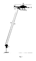
- the Fig. 1 shows an arrangement according to the present invention. This comprises a bottom-side device (1) and a moving platform (5).
- the bottom-side device (1) is set up for measuring the length of the transmission path from the bottom-side device (1) to the moving one Platform (5). Furthermore, the bottom-side device (1) transmits complex measurement or reference signals.
- Fig. 1 does not show the bottom-side high-frequency instrumentation for generating the measurement or reference signals for further signal evaluation.
- the components for distance measurement and signal transmission are mounted on a common axis of motion. This ensures that the measured distances correspond to the transmission path; apart from a possible offset in the longitudinal direction.
- the devices for transmitting the electrically complex measurement signal are arranged next to the distance-measuring devices so that the distance changes of both devices are always the same.
- the electrical measurement signal is modulated onto a free-space laser beam and optically transmitted in parallel to the distance measurement path.
- the Fig. 1 also shows a moving platform (5), eg a remote-controlled miniature helicopter.
- the platform (5) causes by its movement a continuous change in the length of the transmission path.
- a significant phase response is caused, which applies, for example, to compensate for the application of the Antennennahfeldmesstechnik.
- the platform (5) comprises a platform-side device (2).
- the device (2) is the target of the length measurement, for example of a laser beam (3). Furthermore, the device (2) source or receiving part for the (high frequency) measuring or reference signal to be transmitted.
- the platform (5) further comprises an antenna sensor (6) for e.g. Detecting an antenna radiation field and a transmitting and / or receiving device (7) for operating the field sensor (6) and for conversion into an optical transmission medium.
- an antenna sensor (6) for e.g. Detecting an antenna radiation field
- a transmitting and / or receiving device (7) for operating the field sensor (6) and for conversion into an optical transmission medium.
- the device (1) itself is moved and the platform (5) stationary and the device (1) and the platform (5) are both moved.
- the moving devices (1) or platforms (5) may or may not be ground-based (e.g., flying or hovering on a crane).
- the laser beams (3) and (4) are assembled into a beam. This is possible according to the invention for each of the above embodiments.
- electromagnetic or acoustic media may also be used as the transmission medium. This is possible according to the invention for each of the above embodiments.
- the inventive method comprises an accurate and simultaneous measurement of the length of the transmission path.
- the method shown is based on an optical distance measurement, such as by laser interferometry.
- the means for transmitting the electrically complex measurement signal are arranged next to the distance-measuring devices so that the distance changes of both devices are always the same.
- the electrical measurement signal is modulated onto a free-space laser beam and transmitted optically in parallel to the distance measurement path.
- phase can be corrected promptly by means of relevant methods, e.g. by appropriate electrical phase shifter.
- Another method to correct the phase response is to be expected by appropriate post-processing or post-processing on the measured path difference and the wavelength of the high-frequency signal out.
- Another application is the measurement of large satellite ground station antennas or radio telescope antennas.
- the described arrangement can also be used in a slightly modified manner for the validation of, for example, satellite and / or terrestrial navigation / position signals within relatively large dimensions Measurement volume.
- the antenna measuring probe (6) would have to be exchanged with eg GPS / Galileo antennas.
- the position data generated in (7) could then be compared with the much more accurate position measurements of the laser measuring device (1) & (2).
Landscapes
- Engineering & Computer Science (AREA)
- Computer Networks & Wireless Communication (AREA)
- Signal Processing (AREA)
- Power Engineering (AREA)
- Radar Systems Or Details Thereof (AREA)
- Arrangements For Transmission Of Measured Signals (AREA)
- Length Measuring Devices By Optical Means (AREA)
- A Measuring Device Byusing Mechanical Method (AREA)
Abstract
Description
- Die vorliegende Erfindung betrifft eine Vorrichtung, eine Anordnung und ein Verfahren zur drahtlosen Übertragung eines elektrisch komplexen Signals bei der auch die Länge der Übertragungsstrecke gemessen wird und zwar zwecks Korrektur des Phasenganges bei Längenänderung der Übertragungsstrecke.
- Besondere Bedeutung hat diese Methode z.B. bei der komplexen Charakterisierung vor allem großer elektromagnetischer Felder, insbesondere für Antennen-Nahfeldmessungen, denn dadurch könnten z.B. schwebende bzw. fliegende und sich bewegender Plattformen zum Positionieren von Antennenmesssonden eingesetzt werden bei denen eine leitungsgebundene Übertragung von komplexen Signalen, z.B. Mess- oder Referenzsignale, nicht möglich ist bzw. nur unter hohem Risiko / Aufwand realisierbar wäre.
- Zur komplexen Charakterisierung elektromagnetischer Felder, insbesondere im Falle von Hochfrequenz bzw. Antennen-Nahfeldmessungen, ist im Stand der Technik die leitungsgebundene Signalübertragung bekannt.
- Die Verwendung der leitungsgeführten Signalübertragung ist allerdings auf stationäre und in der Größe limitierten Messanlagen beschränkt und zwar auf Grund limitierter Längen bei der Führung bewegter und phasenempfindlicher Hochfrequenzleitungen.
- Ein Problem, welches im Falle einer drahtlosen Übertragung des Messsignals auftritt, ist, dass durch die kontinuierliche Längenänderung der drahtlosen Übertragungsstrecke zwischen der fliegenden Plattform und der Bodenstation, das Problem der Phasenänderung auftritt, welches auf Grund der konstanten Leitungslänge bei einer leitungsgebundenen Übertragung nicht oder nur im geringen Maße durch Dehnung oder Verdrehung der Leitung vorkommt.
- Es ist eine Aufgabe der Erfindung eine Vorrichtung, eine Anordnung und ein Verfahren zu beschreiben, welche eine drahtlose Übertragung eines komplexen Signals erlaubt und eine Möglichkeit bietet den Phasengang zu korrigieren, welcher durch Längenänderung der Übertragungsstrecke verursacht wird.
- Die Aufgabe wird gelöst durch eine Vorrichtung nach Anspruch 1, eine Anordnung nach Anspruch 3 und ein Verfahren nach Anspruch 7.
- Vorteilhafte Ausprägungen der Erfindung sind in den Unteransprüchen zu finden.
- Nachfolgend werden anhand der
Fig. 1 spezielle Ausführungsbeispiele der vorliegenden Erfindung erläutert. - Es zeigen:
-
Fig. 1 - Eine mögliche Realisierungsvariante der Erfindung (lasertechnischer Ansatz) - Die
Fig. 1 zeigt eine Anordnung gemäß der vorliegenden Erfindung. Diese umfasst eine bodenseitige Einrichtung (1) und eine sich bewegende Plattform (5). - Die bodenseitige Einrichtung (1) ist eingerichtet zum Messen der Länge der Übertragungsstrecke von der bodenseitigen Einrichtung (1) zur sich bewegenden Plattform (5). Ferner überträgt die bodenseitige Einrichtung (1) komplexe Mess- bzw. Referenzsignale.
-
Fig. 1 zeigt nicht die bodenseitige Hochfrequenz-Instrumentierung zur Erzeugung der Mess- bzw. Referenzsignale zur weiteren Signalauswertung. - Die Komponenten für die Entfernungsmessung und für die Signalübertragung sind auf einer gemeinsamen Bewegungsachse montiert. Dadurch wird sichergestellt, dass die gemessenen Distanzen der Übertragungsstrecke entspricht; abgesehen von einem eventuellen Versatz in Längsrichtung.
- Mit anderen Worten: Die Einrichtungen zur Übertragung des elektrisch komplexen Messsignals werden so neben den entfernungsmessenden Einrichtungen angeordnet, dass die Entfernungsänderungen beider Einrichtungen immer gleich sind.
- Im gezeigten Beispiel (
Fig. 1 ) wird das elektrische Messsignal auf einen Freiraumlaserstrahl moduliert und optisch parallel zur Entfernungsmessstrecke übertragen. - Die
Fig. 1 zeigt ferner eine sich bewegende Plattform (5), z.B. ein ferngesteuerter Miniatur-Hubschrauber. Die Plattform (5) verursacht durch ihre Bewegung eine kontinuierliche Änderung der Länge der Übertragungsstrecke. Dadurch wird ein erheblicher Phasengang verursacht, welchen es z.B. für die Anwendung der Antennennahfeldmesstechnik zu kompensieren gilt. - Die Plattform (5) umfasst eine plattformseitige Einrichtung (2). Die Einrichtung (2) ist Ziel der Längenmessung, z.B. eines Laserstrahls (3). Ferner ist die Einrichtung (2) Quelle oder Empfangsteil für das zu übertragende (Hochfrequenz-) Mess- bzw. Referenzsignal.
- Die Plattform (5) umfasst ferner einen Antennen-Sensor (6) zum z.B. Detektieren eines Antennenstrahlungsfeldes und eine Sende- und/oder Empfangseinrichtung (7) zum Betreiben des Feldsensors (6) und zur Umsetzung in ein optisches Übertragungsmedium.
- In weiteren Ausführungsformen der Erfindung sind, im Vergleich zu oben beschriebenen Ausführungsformen, die Einrichtung (1) selbst bewegt und die Plattform (5) stationär bzw. die Einrichtung (1) und die Plattform (5) beide bewegt. Die sich bewegenden Einrichtungen (1) oder Plattformen (5) können dabei bodengebunden sein oder nicht (z.B. fliegen oder an einem Kran schwebend).
- In weiteren Ausführungsformen der Erfindung sind die Laserstrahlen (3) und (4) zu einem Strahl zusammengesetzt. Dies ist gemäß Erfindung für jede der obigen Ausführungsformen möglich.
- In weiteren Ausführungsformen der Erfindung können statt der oben beschriebenen optischen Variante, welche einen Laserstrahl verwendet, als Übertragungsmedium auch elektromagnetische oder akustische Medien verwendet werden. Dies ist gemäß Erfindung für jede der obigen Ausführungsformen möglich.
- Als einen ersten Schritt umfasst das erfindungsgemäße Verfahren ein genaues und zeitgleiches Vermessen der Länge der Übertragungsstrecke.
- Dies kann durch Entfernungsmessmethoden unterschiedlicher bekannter Methoden erfolgen z.B. durch satellitengestützte Entfernungsmessung oder durch Ultraschallmessungen. Die dargestellte Methode beruht auf einer optischen Entfernungsmessung, wie z.B. durch Laserinterferometrie.
- Die Einrichtungen zur Übertragung des elektrisch komplexen Messsignals werden so neben den entfernungsmessenden Einrichtungen angeordnet, dass die Entfernungsänderungen beider Einrichtungen immer gleich sind. Im gezeigten Beispiel wird das elektrische Messsignal auf einen Freiraumlaserstrahl moduliert und optisch parallel zur Entfernungsmessstrecke übertragen.
- Mit dieser gewonnenen Information kann durch einschlägige Methoden zeitnah die Phase korrigiert werden z.B. durch entsprechende elektrische Phasenschieber. Eine andere Methode den Phasengang zu korrigieren ist durch entsprechende Nachbehandlung bzw. Nachbearbeitung (Post-Processing) über den gemessenen Wegunterschied und der Wellenlänge des Hochfrequenzsignals heraus zu rechnen.
- Dadurch wird das Phasenproblem gelöst.
- Das beschriebene Verfahren ist für alle oben beschriebenen Ausführungsformen der Erfindung verwendbar.
- Besonders große Vorteile ergeben sich aus der Erfindung durch (1) wesentlich verbesserte Mess- und Verifikationsmöglichkeiten großer und stationärer Antenneneinrichtungen und großer Objekte wie z.B. Flugzeuge bei denen die Strahlungseigenschaften von Antennen im eingebauten Zustand von besonderem Interesse sind und (2) gleiches gilt für Installationen mit hoher Antennendichte, welche sich gegenseitig beeinflussen können, wie z.B. vor allem auf militärischen Schiffen aber auch bei gedrängten Mobilfunk-Sendeinstallationen.
- Eine andere Anwendung ist die Vermessung großer Satellitenbodenstationsantennen bzw. Radioteleskopantennen.
- Neben der Antennenmesstechnik kann die beschriebene Anordnung in leicht modifizierter Weise auch zur Validierung von z.B. satelliten- und/oder terrestrischen Navigations- / Positionssignalen dienen innerhalb relativ großer Messvolumen. Hierzu müsste die Antennenmesssonde (6) mit einer z.B. GPS / Galileo Antennen ausgetauscht werden. Die in (7) generierten Positionsdaten könnten dann mit den wesentlich genaueren Positionsmessungen der Lasermesseinrichtung (1) & (2) verglichen werden.
Claims (7)
- Vorrichtung umfassend
eine Einrichtung zur Messung der Länge einer Übertragungsstrecke zu einer sich bewegenden Plattform (5)
eine Einrichtung zur Übertragung komplexer Mess- bzw. Referenzsignale, wobei
zumindest Bestandteile der Einrichtung zur Übertragung komplexer Mess- bzw. Referenzsignale so neben zumindest Bestandteile der Einrichtung zur Messung der Länge der Übertragungsstrecke zu einer sich bewegenden Plattform (5) angeordnet ist, dass die Änderungen der Länge der Übertragungsstrecke für beide Einrichtungen immer gleich ist. - Vorrichtung gemäß Anspruch 1, wobei
die zumindest Bestandteile der Einrichtung zur Messung der Länge der Übertragungsstrecke und die zumindest Bestandteile der Einrichtung zur Übertragung komplexer Mess- bzw. Referenzsignale auf einer gemeinsamen Bewegungsachse montiert sind. - Anordnung umfassend eine Plattform (5) und eine Einrichtung (1) gemäß einem der Ansprüche 1 oder 2.
- Anordnung nach Anspruch 3, wobei die Einrichtung (1) eine stationäre bodenseitige Einrichtung ist und die Plattform (5) eine sich bewegende Plattform ist.
- Anordnung nach Anspruch 3, wobei sowohl die Einrichtung (1) eine sich bewegende Einrichtung ist und die Plattform (5) eine sich bewegende Plattform ist.
- Anordnung nach Anspruch 3, wobei sowohl die Einrichtung (1) eine sich bewegende Einrichtung ist und die Plattform (5) eine stationäre Einrichtung ist.
- Verfahren zur drahtlosen Übertragung von phasen-kritischen Signalen für eine Vorrichtung gemäß einem der Ansprüche 1 oder 2 bzw. für eine Anordnung gemäß einem der Ansprüche 3 bis 6 umfassend
den Schritt, dass ein Vermessen der Länge der Übertragungsstrecke zeitgleich erfolgt.
Applications Claiming Priority (1)
| Application Number | Priority Date | Filing Date | Title |
|---|---|---|---|
| DE102008024134A DE102008024134B4 (de) | 2008-05-19 | 2008-05-19 | Anordnung und Verfahren zur drahtlosen Übertragung von phasen-kritischen Signalen bei variabler Längenänderung der Übertragungsstrecke |
Publications (3)
| Publication Number | Publication Date |
|---|---|
| EP2124405A2 true EP2124405A2 (de) | 2009-11-25 |
| EP2124405A3 EP2124405A3 (de) | 2017-10-25 |
| EP2124405B1 EP2124405B1 (de) | 2018-08-29 |
Family
ID=41052054
Family Applications (1)
| Application Number | Title | Priority Date | Filing Date |
|---|---|---|---|
| EP09006642.4A Active EP2124405B1 (de) | 2008-05-19 | 2009-05-16 | Anordnung und verfahren zur drahtlosen übertragung von phasenkritischen signalen bei variabler längenänderung der übertragungsstrecke |
Country Status (4)
| Country | Link |
|---|---|
| US (1) | US8125621B2 (de) |
| EP (1) | EP2124405B1 (de) |
| DE (1) | DE102008024134B4 (de) |
| IL (1) | IL198797A (de) |
Cited By (1)
| Publication number | Priority date | Publication date | Assignee | Title |
|---|---|---|---|---|
| CN107632208A (zh) * | 2017-08-09 | 2018-01-26 | 西安电子科技大学 | 一种球面近场天线测量方法及系统 |
Family Cites Families (14)
| Publication number | Priority date | Publication date | Assignee | Title |
|---|---|---|---|---|
| US3788743A (en) * | 1972-03-02 | 1974-01-29 | California Inst Of Techn | Laser receiver system |
| IT1052696B (it) * | 1975-12-18 | 1981-07-20 | Cselt Centro Studi Lab Telecom | Procedimento e dispositivo numerico per la correzione adattativa della fase nella demodulazione coerente di segnali numerici |
| US4054881A (en) * | 1976-04-26 | 1977-10-18 | The Austin Company | Remote object position locater |
| US4894662A (en) * | 1982-03-01 | 1990-01-16 | Western Atlas International, Inc. | Method and system for determining position on a moving platform, such as a ship, using signals from GPS satellites |
| US4734702A (en) * | 1986-02-25 | 1988-03-29 | Litton Systems, Inc. | Passive ranging method and apparatus |
| JP3036807B2 (ja) * | 1990-09-11 | 2000-04-24 | アンリツ株式会社 | 基準信号伝送装置 |
| JP3105867B2 (ja) * | 1998-07-03 | 2000-11-06 | 日本電気株式会社 | 合成開口レーダシステム及びそれに用いるプラットフォーム位置計測方法並びにその制御プログラムを記録した記録媒体 |
| AU769332B2 (en) * | 1999-12-30 | 2004-01-22 | Airbus Defence and Space GmbH | Mobile system and method for characterizing radiation fields outdoors in an extensive and precise manner |
| US6255992B1 (en) * | 2000-04-13 | 2001-07-03 | The United States Of America As Represented By The Secretary Of The Air Force | Self-calibrating large baseline interferometer for very precise emitter location using time difference of arrival and time difference of arrival rate |
| DE10226329A1 (de) * | 2002-06-07 | 2003-12-18 | Deutsche Telekom Ag | Mobiles Kommunikationsendgerät mit Messfunktionen |
| EP1815267B1 (de) * | 2004-11-15 | 2015-06-10 | Nanotron Technologies GmbH | Symmetrisches mehrwegverfahren zur bestimmung des abstandes zweier senderempfänger |
| WO2006095463A1 (ja) * | 2005-03-09 | 2006-09-14 | Omron Corporation | 距離測定装置、距離測定方法、反射体、および通信システム |
| JP2007174244A (ja) * | 2005-12-21 | 2007-07-05 | Canon Inc | 無線通信装置および測距方法 |
| US8157205B2 (en) * | 2006-03-04 | 2012-04-17 | Mcwhirk Bruce Kimberly | Multibody aircrane |
-
2008
- 2008-05-19 DE DE102008024134A patent/DE102008024134B4/de not_active Expired - Fee Related
-
2009
- 2009-05-16 EP EP09006642.4A patent/EP2124405B1/de active Active
- 2009-05-18 IL IL198797A patent/IL198797A/en active IP Right Grant
- 2009-05-18 US US12/467,705 patent/US8125621B2/en not_active Expired - Fee Related
Cited By (2)
| Publication number | Priority date | Publication date | Assignee | Title |
|---|---|---|---|---|
| CN107632208A (zh) * | 2017-08-09 | 2018-01-26 | 西安电子科技大学 | 一种球面近场天线测量方法及系统 |
| CN107632208B (zh) * | 2017-08-09 | 2019-12-24 | 西安电子科技大学 | 一种球面近场天线测量方法及系统 |
Also Published As
| Publication number | Publication date |
|---|---|
| DE102008024134A1 (de) | 2009-11-26 |
| IL198797A (en) | 2015-01-29 |
| US20090284417A1 (en) | 2009-11-19 |
| EP2124405B1 (de) | 2018-08-29 |
| DE102008024134B4 (de) | 2012-04-19 |
| IL198797A0 (en) | 2010-02-17 |
| EP2124405A3 (de) | 2017-10-25 |
| US8125621B2 (en) | 2012-02-28 |
Similar Documents
| Publication | Publication Date | Title |
|---|---|---|
| DE102009053446B4 (de) | Hochfrequenz-Messanlage und Verfahren zum Vermessen eines Hochfrequenz-Testobjekts, insbesondere einer Antenne | |
| EP3497016B1 (de) | Unbemanntes luftfahrzeug zur zerstörungsfreien prüfung einer dreidimensionalen struktur | |
| EP2320240A2 (de) | Verfahren und Vorrichtung zum Vermessen eines Strahlungsfelds | |
| DE3911307A1 (de) | Verfahren zum feststellen, ob zwei hintereinander angeordnete wellen hinsichtlich ihrer mittelachse fluchten oder versetzt sind | |
| DE102007023826A1 (de) | Verfahren und Vorrichtung zur berührungslosen Schwingungsmessung | |
| EP1242829B1 (de) | Mobile anordnung und verfahren zur grossflächigen und genauen charakterisierung von strahlungsfeldern im aussenbereich | |
| DE102019200650A1 (de) | Kalibrierung eines Magnetsensors | |
| WO2012004010A2 (de) | Verfahren und vorrichtung zur bestimmung der position und orientierung eines mobilen senders | |
| DE102019200652A1 (de) | Kalibrierung eines Magnetsenders | |
| DE60211783T2 (de) | Vorrichtung und Verfahren zur Durchführung von Verfolgung eines Signals mit offener Schleife | |
| DE3248879A1 (de) | Verfahren und vorrichtung zur erzeugung kuenstlicher zielmarken in der abbildung eines radars mit synthetischer apertur (sar) | |
| DE2904427A1 (de) | Messvorrichtung zur messung eines sauerstoff-partialdruckes | |
| DE102020204034A1 (de) | Verfahren und Vorrichtung zur Kalibrierung mindestens eines Radarsensors | |
| DE102018104056B3 (de) | Verfahren zur optimierten Anordnung und Ausrichtung eines Feldgerätes | |
| DE102011086401A1 (de) | MR-Datenerfassung in einem dreidimensionalen K-Raum mit einer Anordnung von Datenzeilen gemäß einer Spiral-Phyllotaxis | |
| DE102008024134B4 (de) | Anordnung und Verfahren zur drahtlosen Übertragung von phasen-kritischen Signalen bei variabler Längenänderung der Übertragungsstrecke | |
| DE102011001475A1 (de) | Verfahren und Vorrichtungen zur Positions- und/oder Orientierungsbestimmung | |
| EP2779031B1 (de) | Messverfahren und Messvorrichtung | |
| DE102017117498A1 (de) | System und Verfahren zum Kalibrieren einer Sendeeinheit sowie Wasserfahrzeug mit einem System zum Kalibrieren einer Sendeeinheit | |
| EP2573528A1 (de) | Verfahren und 3d-empfänger zur messung eines vektors mechanischer schwingungen | |
| DE102008005672B4 (de) | Vorrichtung und Verfahren zum Erfassen von Strukturveränderungen eines Bauteils | |
| DE3209235A1 (de) | Einrichtung zur messung der geschwindigkeit | |
| EP2020606B1 (de) | Funksignalbasierte Positionierungsvorrichtung und funksignalbasiertes Positionierungsverfahren | |
| DE3112026C2 (de) | Vorrichtung zur Messung der Lage und Bewegung eines schwingfähigen Körpers | |
| DE102020111207A1 (de) | Vorrichtung zur Messung von Schwingungen eines Objekts mittels Lichtleiter-gestützter Laser-Doppler-Vibrometrie |
Legal Events
| Date | Code | Title | Description |
|---|---|---|---|
| PUAI | Public reference made under article 153(3) epc to a published international application that has entered the european phase |
Free format text: ORIGINAL CODE: 0009012 |
|
| AK | Designated contracting states |
Kind code of ref document: A2 Designated state(s): AT BE BG CH CY CZ DE DK EE ES FI FR GB GR HR HU IE IS IT LI LT LU LV MC MK MT NL NO PL PT RO SE SI SK TR |
|
| PUAL | Search report despatched |
Free format text: ORIGINAL CODE: 0009013 |
|
| AK | Designated contracting states |
Kind code of ref document: A3 Designated state(s): AT BE BG CH CY CZ DE DK EE ES FI FR GB GR HR HU IE IS IT LI LT LU LV MC MK MT NL NO PL PT RO SE SI SK TR |
|
| AX | Request for extension of the european patent |
Extension state: AL BA RS |
|
| RIC1 | Information provided on ipc code assigned before grant |
Ipc: H04L 25/02 20060101AFI20170921BHEP |
|
| STAA | Information on the status of an ep patent application or granted ep patent |
Free format text: STATUS: REQUEST FOR EXAMINATION WAS MADE |
|
| 17P | Request for examination filed |
Effective date: 20171207 |
|
| RAP1 | Party data changed (applicant data changed or rights of an application transferred) |
Owner name: AIRBUS DEFENCE AND SPACE GMBH |
|
| GRAP | Despatch of communication of intention to grant a patent |
Free format text: ORIGINAL CODE: EPIDOSNIGR1 |
|
| STAA | Information on the status of an ep patent application or granted ep patent |
Free format text: STATUS: GRANT OF PATENT IS INTENDED |
|
| INTG | Intention to grant announced |
Effective date: 20180320 |
|
| GRAS | Grant fee paid |
Free format text: ORIGINAL CODE: EPIDOSNIGR3 |
|
| GRAA | (expected) grant |
Free format text: ORIGINAL CODE: 0009210 |
|
| STAA | Information on the status of an ep patent application or granted ep patent |
Free format text: STATUS: THE PATENT HAS BEEN GRANTED |
|
| AK | Designated contracting states |
Kind code of ref document: B1 Designated state(s): AT BE BG CH CY CZ DE DK EE ES FI FR GB GR HR HU IE IS IT LI LT LU LV MC MK MT NL NO PL PT RO SE SI SK TR |
|
| REG | Reference to a national code |
Ref country code: GB Ref legal event code: FG4D Free format text: NOT ENGLISH |
|
| REG | Reference to a national code |
Ref country code: CH Ref legal event code: EP |
|
| REG | Reference to a national code |
Ref country code: AT Ref legal event code: REF Ref document number: 1036487 Country of ref document: AT Kind code of ref document: T Effective date: 20180915 |
|
| REG | Reference to a national code |
Ref country code: IE Ref legal event code: FG4D Free format text: LANGUAGE OF EP DOCUMENT: GERMAN |
|
| REG | Reference to a national code |
Ref country code: DE Ref legal event code: R096 Ref document number: 502009015225 Country of ref document: DE |
|
| REG | Reference to a national code |
Ref country code: NL Ref legal event code: MP Effective date: 20180829 |
|
| REG | Reference to a national code |
Ref country code: LT Ref legal event code: MG4D |
|
| PG25 | Lapsed in a contracting state [announced via postgrant information from national office to epo] |
Ref country code: FI Free format text: LAPSE BECAUSE OF FAILURE TO SUBMIT A TRANSLATION OF THE DESCRIPTION OR TO PAY THE FEE WITHIN THE PRESCRIBED TIME-LIMIT Effective date: 20180829 Ref country code: GR Free format text: LAPSE BECAUSE OF FAILURE TO SUBMIT A TRANSLATION OF THE DESCRIPTION OR TO PAY THE FEE WITHIN THE PRESCRIBED TIME-LIMIT Effective date: 20181130 Ref country code: LT Free format text: LAPSE BECAUSE OF FAILURE TO SUBMIT A TRANSLATION OF THE DESCRIPTION OR TO PAY THE FEE WITHIN THE PRESCRIBED TIME-LIMIT Effective date: 20180829 Ref country code: NL Free format text: LAPSE BECAUSE OF FAILURE TO SUBMIT A TRANSLATION OF THE DESCRIPTION OR TO PAY THE FEE WITHIN THE PRESCRIBED TIME-LIMIT Effective date: 20180829 Ref country code: BG Free format text: LAPSE BECAUSE OF FAILURE TO SUBMIT A TRANSLATION OF THE DESCRIPTION OR TO PAY THE FEE WITHIN THE PRESCRIBED TIME-LIMIT Effective date: 20181129 Ref country code: NO Free format text: LAPSE BECAUSE OF FAILURE TO SUBMIT A TRANSLATION OF THE DESCRIPTION OR TO PAY THE FEE WITHIN THE PRESCRIBED TIME-LIMIT Effective date: 20181129 Ref country code: IS Free format text: LAPSE BECAUSE OF FAILURE TO SUBMIT A TRANSLATION OF THE DESCRIPTION OR TO PAY THE FEE WITHIN THE PRESCRIBED TIME-LIMIT Effective date: 20181229 Ref country code: SE Free format text: LAPSE BECAUSE OF FAILURE TO SUBMIT A TRANSLATION OF THE DESCRIPTION OR TO PAY THE FEE WITHIN THE PRESCRIBED TIME-LIMIT Effective date: 20180829 |
|
| PG25 | Lapsed in a contracting state [announced via postgrant information from national office to epo] |
Ref country code: ES Free format text: LAPSE BECAUSE OF FAILURE TO SUBMIT A TRANSLATION OF THE DESCRIPTION OR TO PAY THE FEE WITHIN THE PRESCRIBED TIME-LIMIT Effective date: 20180829 Ref country code: LV Free format text: LAPSE BECAUSE OF FAILURE TO SUBMIT A TRANSLATION OF THE DESCRIPTION OR TO PAY THE FEE WITHIN THE PRESCRIBED TIME-LIMIT Effective date: 20180829 Ref country code: HR Free format text: LAPSE BECAUSE OF FAILURE TO SUBMIT A TRANSLATION OF THE DESCRIPTION OR TO PAY THE FEE WITHIN THE PRESCRIBED TIME-LIMIT Effective date: 20180829 |
|
| PG25 | Lapsed in a contracting state [announced via postgrant information from national office to epo] |
Ref country code: IT Free format text: LAPSE BECAUSE OF FAILURE TO SUBMIT A TRANSLATION OF THE DESCRIPTION OR TO PAY THE FEE WITHIN THE PRESCRIBED TIME-LIMIT Effective date: 20180829 Ref country code: PL Free format text: LAPSE BECAUSE OF FAILURE TO SUBMIT A TRANSLATION OF THE DESCRIPTION OR TO PAY THE FEE WITHIN THE PRESCRIBED TIME-LIMIT Effective date: 20180829 Ref country code: EE Free format text: LAPSE BECAUSE OF FAILURE TO SUBMIT A TRANSLATION OF THE DESCRIPTION OR TO PAY THE FEE WITHIN THE PRESCRIBED TIME-LIMIT Effective date: 20180829 Ref country code: RO Free format text: LAPSE BECAUSE OF FAILURE TO SUBMIT A TRANSLATION OF THE DESCRIPTION OR TO PAY THE FEE WITHIN THE PRESCRIBED TIME-LIMIT Effective date: 20180829 Ref country code: CZ Free format text: LAPSE BECAUSE OF FAILURE TO SUBMIT A TRANSLATION OF THE DESCRIPTION OR TO PAY THE FEE WITHIN THE PRESCRIBED TIME-LIMIT Effective date: 20180829 |
|
| PG25 | Lapsed in a contracting state [announced via postgrant information from national office to epo] |
Ref country code: DK Free format text: LAPSE BECAUSE OF FAILURE TO SUBMIT A TRANSLATION OF THE DESCRIPTION OR TO PAY THE FEE WITHIN THE PRESCRIBED TIME-LIMIT Effective date: 20180829 Ref country code: SK Free format text: LAPSE BECAUSE OF FAILURE TO SUBMIT A TRANSLATION OF THE DESCRIPTION OR TO PAY THE FEE WITHIN THE PRESCRIBED TIME-LIMIT Effective date: 20180829 |
|
| REG | Reference to a national code |
Ref country code: DE Ref legal event code: R097 Ref document number: 502009015225 Country of ref document: DE |
|
| PLBE | No opposition filed within time limit |
Free format text: ORIGINAL CODE: 0009261 |
|
| STAA | Information on the status of an ep patent application or granted ep patent |
Free format text: STATUS: NO OPPOSITION FILED WITHIN TIME LIMIT |
|
| 26N | No opposition filed |
Effective date: 20190531 |
|
| PG25 | Lapsed in a contracting state [announced via postgrant information from national office to epo] |
Ref country code: SI Free format text: LAPSE BECAUSE OF FAILURE TO SUBMIT A TRANSLATION OF THE DESCRIPTION OR TO PAY THE FEE WITHIN THE PRESCRIBED TIME-LIMIT Effective date: 20180829 |
|
| REG | Reference to a national code |
Ref country code: CH Ref legal event code: PL |
|
| PG25 | Lapsed in a contracting state [announced via postgrant information from national office to epo] |
Ref country code: CH Free format text: LAPSE BECAUSE OF NON-PAYMENT OF DUE FEES Effective date: 20190531 Ref country code: LI Free format text: LAPSE BECAUSE OF NON-PAYMENT OF DUE FEES Effective date: 20190531 Ref country code: MC Free format text: LAPSE BECAUSE OF FAILURE TO SUBMIT A TRANSLATION OF THE DESCRIPTION OR TO PAY THE FEE WITHIN THE PRESCRIBED TIME-LIMIT Effective date: 20180829 |
|
| REG | Reference to a national code |
Ref country code: BE Ref legal event code: MM Effective date: 20190531 |
|
| PG25 | Lapsed in a contracting state [announced via postgrant information from national office to epo] |
Ref country code: LU Free format text: LAPSE BECAUSE OF NON-PAYMENT OF DUE FEES Effective date: 20190516 |
|
| PG25 | Lapsed in a contracting state [announced via postgrant information from national office to epo] |
Ref country code: TR Free format text: LAPSE BECAUSE OF FAILURE TO SUBMIT A TRANSLATION OF THE DESCRIPTION OR TO PAY THE FEE WITHIN THE PRESCRIBED TIME-LIMIT Effective date: 20180829 |
|
| PG25 | Lapsed in a contracting state [announced via postgrant information from national office to epo] |
Ref country code: IE Free format text: LAPSE BECAUSE OF NON-PAYMENT OF DUE FEES Effective date: 20190516 |
|
| PG25 | Lapsed in a contracting state [announced via postgrant information from national office to epo] |
Ref country code: BE Free format text: LAPSE BECAUSE OF NON-PAYMENT OF DUE FEES Effective date: 20190531 |
|
| PG25 | Lapsed in a contracting state [announced via postgrant information from national office to epo] |
Ref country code: PT Free format text: LAPSE BECAUSE OF FAILURE TO SUBMIT A TRANSLATION OF THE DESCRIPTION OR TO PAY THE FEE WITHIN THE PRESCRIBED TIME-LIMIT Effective date: 20181229 |
|
| REG | Reference to a national code |
Ref country code: AT Ref legal event code: MM01 Ref document number: 1036487 Country of ref document: AT Kind code of ref document: T Effective date: 20190516 |
|
| PG25 | Lapsed in a contracting state [announced via postgrant information from national office to epo] |
Ref country code: AT Free format text: LAPSE BECAUSE OF NON-PAYMENT OF DUE FEES Effective date: 20190516 |
|
| PG25 | Lapsed in a contracting state [announced via postgrant information from national office to epo] |
Ref country code: CY Free format text: LAPSE BECAUSE OF FAILURE TO SUBMIT A TRANSLATION OF THE DESCRIPTION OR TO PAY THE FEE WITHIN THE PRESCRIBED TIME-LIMIT Effective date: 20180829 |
|
| PG25 | Lapsed in a contracting state [announced via postgrant information from national office to epo] |
Ref country code: MT Free format text: LAPSE BECAUSE OF FAILURE TO SUBMIT A TRANSLATION OF THE DESCRIPTION OR TO PAY THE FEE WITHIN THE PRESCRIBED TIME-LIMIT Effective date: 20180829 Ref country code: HU Free format text: LAPSE BECAUSE OF FAILURE TO SUBMIT A TRANSLATION OF THE DESCRIPTION OR TO PAY THE FEE WITHIN THE PRESCRIBED TIME-LIMIT; INVALID AB INITIO Effective date: 20090516 |
|
| PG25 | Lapsed in a contracting state [announced via postgrant information from national office to epo] |
Ref country code: MK Free format text: LAPSE BECAUSE OF FAILURE TO SUBMIT A TRANSLATION OF THE DESCRIPTION OR TO PAY THE FEE WITHIN THE PRESCRIBED TIME-LIMIT Effective date: 20180829 |
|
| PGFP | Annual fee paid to national office [announced via postgrant information from national office to epo] |
Ref country code: GB Payment date: 20220520 Year of fee payment: 14 Ref country code: FR Payment date: 20220523 Year of fee payment: 14 |
|
| GBPC | Gb: european patent ceased through non-payment of renewal fee |
Effective date: 20230516 |
|
| PG25 | Lapsed in a contracting state [announced via postgrant information from national office to epo] |
Ref country code: GB Free format text: LAPSE BECAUSE OF NON-PAYMENT OF DUE FEES Effective date: 20230516 |
|
| PG25 | Lapsed in a contracting state [announced via postgrant information from national office to epo] |
Ref country code: FR Free format text: LAPSE BECAUSE OF NON-PAYMENT OF DUE FEES Effective date: 20230531 |
|
| PGFP | Annual fee paid to national office [announced via postgrant information from national office to epo] |
Ref country code: DE Payment date: 20250521 Year of fee payment: 17 |