EP2124231A2 - Aperture for an imaging device - Google Patents
Aperture for an imaging device Download PDFInfo
- Publication number
- EP2124231A2 EP2124231A2 EP09160478A EP09160478A EP2124231A2 EP 2124231 A2 EP2124231 A2 EP 2124231A2 EP 09160478 A EP09160478 A EP 09160478A EP 09160478 A EP09160478 A EP 09160478A EP 2124231 A2 EP2124231 A2 EP 2124231A2
- Authority
- EP
- European Patent Office
- Prior art keywords
- radiation
- axis
- additional
- aperture
- gap
- Prior art date
- Legal status (The legal status is an assumption and is not a legal conclusion. Google has not performed a legal analysis and makes no representation as to the accuracy of the status listed.)
- Withdrawn
Links
Images


Classifications
-
- G—PHYSICS
- G21—NUCLEAR PHYSICS; NUCLEAR ENGINEERING
- G21K—HANDLING OF PARTICLES OR IONISING RADIATION NOT OTHERWISE PROVIDED FOR; IRRADIATION DEVICES; GAMMA RAY OR X-RAY MICROSCOPES
- G21K1/00—Arrangements for handling particles or ionising radiation, e.g. focusing or moderating
- G21K1/02—Arrangements for handling particles or ionising radiation, e.g. focusing or moderating using diaphragms, collimators
-
- G—PHYSICS
- G21—NUCLEAR PHYSICS; NUCLEAR ENGINEERING
- G21K—HANDLING OF PARTICLES OR IONISING RADIATION NOT OTHERWISE PROVIDED FOR; IRRADIATION DEVICES; GAMMA RAY OR X-RAY MICROSCOPES
- G21K2207/00—Particular details of imaging devices or methods using ionizing electromagnetic radiation such as X-rays or gamma rays
Definitions
- the invention relates to a diaphragm, in particular for an imaging device, according to the preamble of claim 1.
- the radiation source can be, for example, the effective focal spot on the anode of an x-ray tube or surface-distributed radiating material.
- the latter can be radioactive waste distributed over a room in a collecting bin, whereby alleged discrepancies between declaration and actual content must be clarified.
- Further examples of radiation sources whose shape one wishes to image are deposits with uranium-containing ores or nuclear facilities, in which it is often not only of importance to determine the nature of the radiation, but also to determine the spatial structure of the radiation sources.
- the sources mentioned, which generate the high-energy radiation directly are also those that generate them by X-ray or Gammaschenstreuung.
- the thickness of the material for the pinhole diaphragm must be large, that is to say in relation to the half-value thickness of the intensity of the radiation used for imaging. Therefore, the achievable image quality is essentially determined by aperture diameter and material thickness and density. Often, therefore, one obtains at best a shadow image of the actual pinhole, wherein the pinhole, which is to serve for imaging, due to the wall thickness becomes a collimator, which can pass only a straight-line beam. Therefore, the aperture in the hole cameras is often trumpet-shaped with the narrow spot to the radiation source designed so as not to lose the imaging properties completely.
- the DE 690 01 117 discloses a device for detecting radiation sources in real time.
- the device comprises a collimator which is delimited by a wall in the form of a double cone, the double cone being formed from two cones of the same opening angle, which are set opposite each other at the vertex.
- the vertex forms the pinhole of the resulting camera.
- DD 240 091 a rotating diaphragm system, which consists of several concentrically arranged around the optical axis hollow cones.
- Each hollow cone consists of half of the respective radiation strongly or weakly absorbing material, the hollow halves are inserted into each other so that always hollow cone halves of different materials adjoin one another.
- Another mechanically moving solution is from the DE 40 00 507 known, in which a slit aperture acts like the opening of a pinhole camera.
- the relative movement of the slit diaphragm to the detector exposes the radiation scattered from various points of the test object to the detector. Due to the relative position of the slit, it is predetermined from which depth of the test object secondary radiation is detected by a detector.
- a solution for expanding the field of view in a pinhole camera is from the DE 196 03 212 in which the core of the camera has a cylindrical borehole crystal which is terminated by a pinhole collimator, which is conically arched in the region of the borehole. In the center of the collimator is an aperture. Depending on the shape of the collimator, the field of view has an opening angle of up to approximately 120 °.
- the diaphragm is not based on a mechanically moving solution and can be realized with almost any material thickness, without losing its imaging properties.
- the diaphragm is suitable for limiting radiation originating from a radiation source, in particular high-energy radiation, and for directing it to an imaging region along an optical axis x according to the hole-camera principle.
- the diaphragm comprises the radiation at least partially absorbing regions, and in the diaphragm there is a gap or at least one radiation absorbing portion which has at least a first non-planar surface and a second non-planar surface which separates it from the radiation delimit at least partially absorbent areas.
- the imaging quality, the image size and the radiation yield are subject to restrictions.
- the imaging quality can be increased; However, this is simultaneously the pictured Restricted range in y- direction and reduced the beam yield.
- the slit width By increasing the slit width, the imaged area in the y- direction is expanded and the beam yield is increased, but at the same time the imaging quality is lowered.
- the object of the invention is therefore to provide a diaphragm for a pinhole camera, which has the advantages of the published patent application DE 10 2005 029 674 A1 disclosed aperture, but achieves a better imaging quality and / or a larger imaging range and / or a higher beam efficiency.
- Another object of the invention is to provide a diaphragm with better imaging quality and / or larger imaging range and / or higher beam efficiency, which after a comparison with that in the German patent application with the file reference 10 2007 057 261.3 disclosed methods of making the disclosed in the publication DE 10 2005 029 674 A1 disclosed aperture can be produced only slightly modified method.
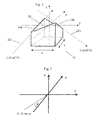
- the description of the surface contours is based on a three-dimensional Cartesian coordinate system whose origin lies on the first non-planar surface without restriction of generality (cf. FIG. 2 ).
- the mode of operation of the diaphragm can be explained by considering a beam with a directional vector (1, y s , z s ), ie a beam which propagates in the direction of the positive optical axis x.
- a direction vector (1,0, tan ⁇ ) cf. FIG.
- the gap already described or the region which absorbs little radiation is referred to here as the first gap or the radiation having a low absorption, since the diaphragm according to the invention has at least one additional gap or at least one additional region which absorbs the radiation to a small extent.
- the low radiation absorbing regions may be filled with a suitable material which absorbs the relevant radiation less than the radiation at least partially absorbing regions, the material being in the form of a separate insert or a coating applied to at least one of the non-planar surfaces can.
- a gap is also to be understood as meaning a region which absorbs the radiation to a low degree and which is filled with material.
- non-planar surfaces is meant any surface that is not flat, such as curved and curved surfaces.
- affine mapping refers to an image of the three-dimensional space on itself, which maps each straight line to a straight line. Such a map can be vectored with respect to a given affine, ie, rectilinear, coordinate system by a mapping rule of the form x ⁇ A x + b describe, where x the vector describing the point to be imaged, A any regular 3x3 matrix and b is an arbitrary three-vector.
- isometry refers to an isometric mapping of the three-dimensional space to itself, ie a rigid body movement that leaves distances and angles invariant.
- An isometry is an affine image in whose vector representation with respect to a Cartesian coordinate system the matrix A is orthogonal.
- the term "shear along the direction A parallel to the plane B" denotes an affine map which shifts each point of the space along the direction A parallel to the plane B by a distance proportional to the distance of the point from the plane B.
- each additional gap has at least one first additional non-planar surface and a second additional non-planar surface which delimits it from the regions which at least partially absorb the radiation
- the contour of the first additional nonplanar surface after application of the associated affine map can each be at least partially described by the same function z ( x , y ), by which the first non-planar surface of the first gap can be at least partially described, and the contour of the second additional non-planar surface is at least partially complementary to the contour of the first additional non-planar surface, it is achieved that the additional column each have similar imaging properties as the first gap.
- the set of affine mappings which comprises the identity mapping for the first gap and the associated affine mapping for each additional gap can be placed in a sequence in such a way that an affine image generating the sequence exists, such that for each pair of affine maps following each other in the sequence, the affine image of the pair following in the sequence is obtained by concatenating the affine image of the pair preceding the sequence with the sequence-generating affine map. This ensures that the sub-images caused by the individual gaps are in a particularly simple and regular relationship to each other.
- the associated affine map is an isometry.
- the additional gaps can be formed by applying a method, which essentially corresponds to the method used to form the first gap, after a movement of the diaphragm corresponding to the respective isometry has been carried out.
- the sequence of affine images is generated by an isometry, it is further achieved that the formation of all gaps in each case the same movement before application of the applied method for forming a gap method is executed.
- the associated isometry can be described in each case as concatenation of a first isometry and a second isometry, each of the first and second isometries each having either a translation along a coordinate axis or a rotation around one is parallel to a coordinate axis or coincident with a coordinate axis axis.
- each of the first and second isometries may be a rotation about an axis parallel to a coordinate axis or coincident with a coordinate axis.
- the first isometry is in each case a rotation about a respective angle ⁇ about a first axis, which lies in the x - y plane and runs parallel to the y- axis or coincides with the y -axis
- the second isometry each rotation about a respective angle ⁇ about a second axis, which lies in the xz plane and parallel to the z- axis or coincides with the z- axis. It is thereby achieved that the sub-images caused by the gaps adjoin one another at least at a predetermined distance from the y - z plane and result in a consistent overall image there.
- the angle ⁇ can each be 0 °.
- the first axis can coincide with the y- axis. It is thereby achieved that the sub-images caused by the gaps adjoin one another independently of the distance from the yz-plane and result in a consistent overall image.
- the associated affine image is in each case a shear for each additional gap.
- the shear is in each case a shear in the y- direction parallel to the y- z plane. This ensures that the imaging surface is increased irrespective of the distance of the imaging plane to the diaphragm center and the distortions or blurring in the superposition of the partial images caused by the column are particularly low.
- A, B, C and n are constants.
- the constant A may have the value 0, and the constant B may have the value 0.
- the shape of the first non-planar surface corresponds to the shape of the first nonplanar surface of the laid-open publication DE 10 2005 029 674 A1 disclosed aperture.
- each additional gap that the contour of the second additional non-planar surface relative to the contour of the first additional non-planar surface is at least partially in the same position in which the contour of the second non-planar surface is relative to the contour of the first non-planar surface located. This ensures that the mapping properties of the column match and all columns can be formed using the same procedure.
- the first gap has a gap width h (y) which is essentially constant in a direction parallel to the optical axis x.
- the visible in the direction of the beam passage then has a size which is proportional to the expression H 2 y ⁇ f y ⁇ y is. If the gap width h (y) is chosen so that the is constant, beams of equal intensity are imaged with the same imaging quality.
- the width of the column is variable.
- the imaging properties of the diaphragm can be adapted to different situations, in particular to different intensities of the investigated radiation sources.
- the first gap fulfills the ideal hole camera principle only for beam bundles whose directional vectors lie in the xz plane, it is provided in a further embodiment of the invention that the radiation-absorbing regions are arranged rotatably about the optical axis x, so that the Column can be rotated.
- the radiation-absorbing regions are arranged rotatably about the optical axis x, so that the Column can be rotated.
- the building material for the diaphragm all materials are in question, which are able to absorb the radiation emitted by the radiation source effectively.
- these are heavy metals with a high atomic number, for example copper or tungsten.
- plastics with a high hydrogen content for example polyethylene, are suitable.
- the additional gaps can be formed by the same or a similar method as the first gap.
- the column according to the in the German patent application with the file number 10 2007 057 261.3 disclosed methods are formed.
- the invention therefore also provides a method of manufacturing a shutter as described above in which relative movement is performed between a cutting tool capable of cutting along a straight line and a workpiece such that the cutting tool traverses the workpiece a line intersecting a beam path in the diaphragm to be made, wherein the relative movement is repeated at least once, and wherein before each repetition of the relative movement, the workpiece is moved.
- the workpiece is cut along a fixed first direction. Furthermore, it is preferred that a rotational movement of the workpiece about a first axis of rotation, which runs along a second direction perpendicular to the cutting direction of the cutting tool, and at the same time a translational movement of the workpiece along the second direction are performed. Preferably, the rotational movement and the translational movement of the workpiece are linearly coupled.
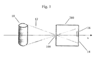
- FIG. 1 illustrates the Lochensekar at an imaging device 200.
- a radiation source 10 for example, a test body, high-energy radiation 12, in particular X-rays or gamma rays, emitted.
- the radiation 12 strikes a diaphragm 100, by which it is limited and directed along an optical axis x according to the Lochtrekos on an imaging region 14.
- the imaging region 14 is typically a projection surface on which an image of the test body 10 is generated.
- a receiving unit 16 which is sensitive to the radiation 12, in particular a detector or a camera.
- the diaphragm 100 comprises the radiation 12 at least partially absorbing regions.
- a first radiation 12 absorbing region 18 is in FIG. 2 shown. It is delimited by a first non-planar surface 20 of a slit or the region 12 of low-absorbing radiation (not shown).
- the position of the Cartesian coordinate system is chosen so that its origin lies on the first non-planar outer surface 20, without limiting the generality.
- the x-axis coincides with the optical axis.
- surface C ⁇ 0; however, C> 0 can also be selected.
- the radiation absorbing portion 18 in this case is a parallelepiped, with respect to the coordinate system symmetrical body of suitable absorbent material (width a, depth b). For hard radiation this is a heavy metal with the highest possible density, for example copper or tungsten.
- the beam paths 22a, b correspond to direction vectors (1, 0, ⁇ aC / 2). For every direction vector (1, 0, z) for which - aC / 2 ⁇ z ⁇ aC / 2, there is exactly one parallel edge on the non-planar surface 20. For each direction vector with non-vanishing y-component, on the other hand the corresponding lines on the non-planar surface 20 are not linear.
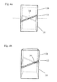
- FIGS. 4a, b show first for illustration for two viewing angles, a diaphragm according to published patent application DE 10 2005 029 674 A1 with a single gap 32 and two radiation-absorbing areas 18 and 26.
- a view through the gap 32 in a straight direction is possible only at one point.
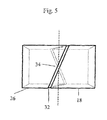
- the cleavage direction can optionally be horizontal ( FIG. 4 ) or vertical ( FIG. 5 ) be aligned.
- distances to the object can be estimated on the basis of large-area contours and, if necessary, measured.
- FIG. 6 shows schematically a test arrangement.
- a continuously radiating, powerful x-ray tube 46 generates radiation, which is hidden by an all-round shield, here a lead wall with window 48.
- the radiation passing through the window of the lead wall 48 falls onto an aluminum plate as scattering filter 50.
- the actual test object 10 is arranged between the scattering filter 50 and the diaphragm 100 according to the invention, which is integrated in a shielding wall 30 made of lead.
- an X-ray film or an image storage film (English: phosphor imaging plate) is used in a cassette.
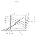
- FIG. 7 shows a perspective view of a panel according to a first embodiment of the present invention.
- the shutter of the present invention also includes additional gaps 32a and 32b defined by first and second additional non-planar surfaces, respectively, from the radiation absorbing regions 28a and 26, and 18 and 28b, respectively. It is, as in FIGS. 8 and 9 in more detail, each of the first additional non-planar surface is tilted relative to the first non-planar surface by an angle ⁇ about an axis parallel to the y-axis and rotated by an angle ⁇ about the z-axis, and the second additional not plane surface is in each case complementary to the first additional non-planar surface.
- the diaphragm has two additional gaps; however, as many additional columns as desired can be added to further enhance the imaging properties of the aperture.
- the spatial position of each further gap preferably results from the spatial position of the adjacent gap by the same isometry.
- FIG. 8 shows a cross-sectional view of the aperture of FIG. 7 in sectional plane A in the direction of view a, with the first gap 32, the additional gaps 32a and 32b and the radiation-absorbing areas 18, 28a, 28b and 26.
- the additional column 32a and 32b are each tilted with respect to the first gap 32 by an angle ⁇ about an axis parallel to the y axis through the receiving unit 16 extending axis, so that the central rays of the column converge at the receiving unit 16.
- the angle ⁇ can be kept so small that distortions due to the oblique incidence on the image surface are negligible and the known approximations for small angles (sin ⁇ ⁇ tan ⁇ ) can be applied.
- FIG. 9 shows a plan view of the central rays of the diaphragm of FIG. 7 in the direction b.
- the central beams 36a, 36b of the additional column are rotated relative to the central beam 36 of the first gap by an angle ⁇ about the z-axis.
- the superimposed floor plans serve only to clarify the alignment and do not relate to the visor body.
- the angle ⁇ can be chosen freely; it determines the distance or overlap of the adjacent partial images.
- FIG. 10 shows a perspective view of the aperture of FIG. 7 with the first gap 32, the additional gaps 32a and 32b, the radiation absorbing areas 18, 28a, 28b and 26 and the central beam 36 of the first gap 32 and the central beams 36a and 36b of the additional gaps 32a and 32b.
- all the beams from a passage direction open exactly onto a horizontal image axis 38, so that a sequence of the partial images caused by the gaps is ensured.
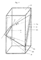
- FIG. 11 shows a perspective view of a panel according to a second embodiment of the present invention.
- This diaphragm also has a first gap 32 and additional gaps 32a and 32b as well as the radiation 12 absorbing regions 18, 28a, 28b and 26.
- C ⁇ 0 is selected; however, C> 0 can also be selected.
- the second embodiment of the present invention differs from the first embodiment in two essential features.
- the axis with respect to which the additional gaps are tilted by the angle ⁇ relative to the first gap coincides in this embodiment with the y-axis.
- no fixed distance is predetermined in this embodiment in which the receiving unit 16 must be arranged relative to the diaphragm.
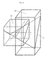
- FIG. 12 shows a perspective view to illustrate the structure of the aperture of FIG. 11 ,
- the first gap 32 is shown.
- the outline of the panel 100 of the first embodiment is shown for comparison.
- the lines of intersection of the first gap 32 with the outer boundary surfaces of the two diaphragms are shown.
- Aperture 100 ' is truncated at x 0 ⁇ 0 at x coordinate x 0 as compared to aperture 100; on the other hand, it is widened in the direction of higher x-coordinates compared to the stop 100.
- the beam guidance is unchanged from the first embodiment.
- the y-axis comes to lie outside the diaphragm body. This makes it possible to arrange the column tilted relative to each other about the y-axis, without causing the visor body falls apart. This makes it particularly easy to add more columns, and the individual columns can be made narrower. For example, to make a panel according to this second embodiment of the present invention, many columns could be realized by stacking correspondingly shaped panels with wedge-shaped profiles.
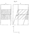
- FIG. 13 Fig. 12 shows a z-direction plan view of a shear used in a third embodiment of the present invention. It is a shear in the y direction parallel to the yz plane.
- FIG. 13a shows the unsaved first gap
- FIG. 13b shows the sheared additional gap.
- the shear angle ⁇ is plotted, which forms the sheared x- axis with the unsecured x- axis.
- FIG. 14 shows a perspective view illustrating the construction of a diaphragm according to the third embodiment of the present invention.
- the first gap 32 and an additional, according to the in FIG. 13 Shear sheared gap 32a are shown.
- Limits are set only by the mechanical stability of the visor material and by the need to maintain a sufficient thickness for the shielding layer. Due to the shear, the gaps do not interfere with each other in their course.
- the outline of the bezel 100 of the first embodiment and the bezel 100 'of the second embodiment shown.
- the cut lines of the first gap 32 with the contour of the visor 100 ' are the lines of intersection of the additional gap 32a with the outline of the orifice 100 "and the shear angle ⁇ shown the aperture 100".
- Shear shear shown additional gap 32a finds place in it.
- FIG. 15 is a perspective view of a panel according to a fourth embodiment of the present invention. Again, the first gap 32 and an additional gap 32a are shown, with further gaps being added.
- the bezel according to the fourth embodiment of the present invention consists of two bezels according to the third embodiment of the present invention, which are joined together at their central axes. As a result, a higher wall thickness for particularly high-energy radiation can be achieved.
Landscapes
- Physics & Mathematics (AREA)
- Spectroscopy & Molecular Physics (AREA)
- Engineering & Computer Science (AREA)
- General Engineering & Computer Science (AREA)
- High Energy & Nuclear Physics (AREA)
- Measurement Of Radiation (AREA)
- Analysing Materials By The Use Of Radiation (AREA)
- Diaphragms For Cameras (AREA)
Abstract
Description
Die Erfindung betrifft eine Blende, insbesondere für eine bildgebende Einrichtung, gemäß dem Oberbegriff des Anspruchs 1.The invention relates to a diaphragm, in particular for an imaging device, according to the preamble of claim 1.
Häufig stellt sich das Problem, die Form verdeckter Quellen hochenergetischer Strahlung mit unbekannter Struktur beziehungsweise räumlichem Aufbau zu ermitteln. Bei der Strahlenquelle kann es sich beispielsweise um den effektiven Brennfleck auf der Anode einer Röntgenröhre oder um flächig verteiltes strahlendes Material handeln. Letzteres können über einen Raum verteilte radioaktive Abfälle in einer Sammeltonne sein, wobei vermeintliche Diskrepanzen zwischen Deklarierung und tatsächlichem Inhalt zu klären sind. Weitere Beispiele für Strahlenquellen, deren Gestalt man abbilden möchte, sind Lagerstätten mit uranhaltigen Erzen oder kerntechnische Anlagen, bei denen es oftmals nicht nur von Belang ist, die Natur der Strahlung zu ermitteln, sondern auch die räumliche Struktur der Strahlenquellen zu bestimmen. Neben den genannten Quellen, welche die hochenergetische Strahlung direkt erzeugen, sind auch solche zu nennen, welche diese durch Röntgen- bzw. Gammarückstreuung erzeugen.Frequently the problem arises of determining the form of hidden sources of high-energy radiation of unknown structure or spatial structure. The radiation source can be, for example, the effective focal spot on the anode of an x-ray tube or surface-distributed radiating material. The latter can be radioactive waste distributed over a room in a collecting bin, whereby alleged discrepancies between declaration and actual content must be clarified. Further examples of radiation sources whose shape one wishes to image are deposits with uranium-containing ores or nuclear facilities, in which it is often not only of importance to determine the nature of the radiation, but also to determine the spatial structure of the radiation sources. In addition to the sources mentioned, which generate the high-energy radiation directly, are also those that generate them by X-ray or Gammarückstreuung.
Um die Gestalt solcher Strahlenquellen abzubilden, ist es naheliegend, das Prinzip einer Fotokamera anzuwenden. Es können dabei recht unterschiedliche Flächendetektoren eingesetzt werden: Filmmaterial, Speicherplatten, Speicherfolien, Halbleiter-Flachdetektoren, Vidicams, Bildverstärker oder Konverterfolien. Da solche Aufnahmen auch und vor allem in Umgebungen anfallen können, in die sich nach Möglichkeit Personen nicht hineinbegeben sollten, muss eine möglichst einfache Bedienbarkeit sichergestellt werden. Die einfachste Funktionalität und Handhabung wäre ein fernbedientes Platzieren eines entsprechenden Gerätes mit einer Rückholung nach der Expositionzeit ohne jegliche Betätigung irgendwelcher Bedienungselemente.To illustrate the shape of such radiation sources, it is obvious to apply the principle of a camera. Quite different area detectors can be used: film material, storage disks, storage foils, semiconductor flat detectors, vidicams, image intensifiers or converter foils. Since such recordings can also and especially occur in environments in which persons should not enter, if possible, the simplest operability must be ensured. The simplest functionality and handling would be to remotely place a corresponding device with a retrieval after the exposure time without any operation of any controls.
Es ist bekannt, bei der Abbildung mit Hilfe energiereicher Strahlung das Lochkameraprinzip zu benutzen. Bei einer Lochkamera oder Camera obscura erzeugt ein kleines Loch auf einer Projektionsfläche ein Abbild von angestrahlten oder strahlenden Gegenständen. Dabei beschränkt der kleine Durchmesser der Blende die einfallenden Strahlenbündel auf einen kleinen Öffnungswinkel und verhindert so die vollständige Überlappung der Strahlen in der Abbildungsfläche. Strahlen von einem oberen Bereich eines strahlenden Körpers fallen auf den unteren Rand der Projektionsfläche, während umgekehrt Strahlen vom unteren Bereich auf den oberen Rand der Projektionsfläche abgebildet werden. Somit wird jeder Punkt des Gegenstandes als Scheibchen auf der Projektionsfläche abgebildet, so dass die Überlagerung der Scheibchenbilder ein Bild des strahlenden Körpers liefert, dessen Auflösung vom Abstand des strahlenden Körpers und der Form der Blende abhängt.It is known to use the Lochkameraprinzip when imaging with the help of high-energy radiation. In a pinhole camera or camera obscura , a small hole on a projection surface produces an image of illuminated or radiating objects. The small diameter of the diaphragm limits the incident beam to a small opening angle and thus prevents the complete overlap of the beams in the imaging surface. Radiation from an upper portion of a radiating body is incident on the lower edge of the projection surface while, conversely, rays are incident from the lower portion the upper edge of the projection surface are mapped. Thus, each point of the object is imaged as slices on the projection surface, so that the superimposition of the slice images provides an image of the radiating body whose resolution depends on the distance of the radiating body and the shape of the diaphragm.
Bei hochenergetischer Strahlung tritt das Problem auf, dass wegen ihres hohen Durchdringungsvermögens die Dicke des Materials für die Lochblende groß, das heißt im Verhältnis zur Halbwertsdicke der Intensität der zur Abbildung benutzten Strahlung gewählt werden muss. Deshalb wird die erreichbare Abbildungsgüte im Wesentlichen durch Blendendurchmesser und Materialdicke und -dichte bestimmt. Oft erhält man daher bestenfalls ein Schattenbild der eigentlichen Lochblende, wobei die Lochblende, die zur Abbildung dienen soll, aufgrund der Wanddicke zum Kollimator wird, der nur ein gradliniges Strahlenbündel passieren lässt. Deshalb wird oftmals die Blende in den Lochkameras trompetenförmig mit der engen Stelle zur Strahlenquelle gestaltet, um die abbildenden Eigenschaften nicht vollends zu verlieren.The problem with high-energy radiation is that, because of its high permeability, the thickness of the material for the pinhole diaphragm must be large, that is to say in relation to the half-value thickness of the intensity of the radiation used for imaging. Therefore, the achievable image quality is essentially determined by aperture diameter and material thickness and density. Often, therefore, one obtains at best a shadow image of the actual pinhole, wherein the pinhole, which is to serve for imaging, due to the wall thickness becomes a collimator, which can pass only a straight-line beam. Therefore, the aperture in the hole cameras is often trumpet-shaped with the narrow spot to the radiation source designed so as not to lose the imaging properties completely.
Die
Um den Öffnungswinkel einer Lochkamera für energiereiche Strahlung bei Erhalt eines hohen Auflösungsvermögens zu vergrößern, schlägt die
Eine weitere mechanisch bewegte Lösung ist aus der
Eine Lösung zur Erweiterung des Gesichtsfeldes bei einer Lochkamera ist aus der
Aus dem Stand der Technik sind außerdem vielfältige Ansätze bekannt, das Problem der Penetration harter Strahlung für eine Blende mit einer möglichst geringen Schichtdicke zu lösen. Zu nennen sind zum Beispiel detektornahe Flächenkollimatoren mit Schrägplatten, welche aus der
Nachteil aller beschriebenen Lösungen ist, dass bei energiereicher Strahlung aufgrund der erforderlichen Materialdicke eine erhebliche Abweichung vom idealen Lochkameraprinzip vorliegt, außer wenn mechanisch bewegte Lösungen zum Einsatz kommen, welche sehr aufwändig sind.Disadvantage of all solutions described is that with high-energy radiation due to the required material thickness, a significant deviation from the ideal hole camera principle is present, except when mechanically moving solutions are used, which are very expensive.
In der Offenlegungsschrift
Nachteilig ist an dieser Blende, dass die Abbildungsqualität, die Abbildungsgröße und die Strahlenausbeute Beschränkungen unterworfen sind. Durch Verringerung der Spaltbreite lässt sich zwar die Abbildungsqualität erhöhen; dadurch wird jedoch gleichzeitig der abgebildete Bereich in y-Richtung eingeschränkt und die Strahlenausbeute verringert. Umgekehrt wird durch Erhöhung der Spaltbreite der abgebildete Bereich in y-Richtung ausgedehnt und die Strahlenausbeute erhöht, gleichzeitig jedoch die Abbildungsqualität herabgesetzt.The disadvantage of this diaphragm is that the imaging quality, the image size and the radiation yield are subject to restrictions. By reducing the gap width, the imaging quality can be increased; However, this is simultaneously the pictured Restricted range in y- direction and reduced the beam yield. Conversely, by increasing the slit width, the imaged area in the y- direction is expanded and the beam yield is increased, but at the same time the imaging quality is lowered.
Aufgabe der Erfindung ist es daher, eine Blende für eine Lochkamera anzugeben, welche die Vorteile der in der Offenlegungsschrift
Eine weitere Aufgabe der Erfindung ist es, eine Blende mit besserer Abbildungsqualität und/oder größerem Abbildungsbereich und/oder höherer Strahlenausbeute anzugeben, welche nach einem gegenüber dem in der deutschen Patentanmeldung mit dem Aktenzeichen
Erfindungsgemäß werden die Aufgaben mittels einer Blende, insbesondere für eine bildgebende Einrichtung, mit den im Anspruch 1 genannten Merkmalen gelöst.According to the invention the objects are achieved by means of a diaphragm, in particular for an imaging device, with the features mentioned in claim 1.
Insbesondere weist die erfindungsgemäße Blende gemäß dem Oberbegriff des Anspruchs 1 die oben beschriebenen vorteilhaften Merkmale der in der Offenlegungsschrift
Für die Beschreibung der Oberflächenkonturen wird ein dreidimensionales kartesisches Koordinatensystem zugrunde gelegt, dessen Ursprung ohne Beschränkung der Allgemeinheit auf der ersten nicht-ebenen Oberfläche liegt (vergleiche
Der bereits beschriebene Spalt oder die Strahlung gering absorbierende Bereich wird hier als erster Spalt oder die Strahlung gering absorbierender Bereich bezeichnet, da die erfindungsgemäße Blende mindestens einen zusätzlichen Spalt oder zumindest mindestens einen zusätzlichen die Strahlung gering absorbierenden Bereich aufweist.The gap already described or the region which absorbs little radiation is referred to here as the first gap or the radiation having a low absorption, since the diaphragm according to the invention has at least one additional gap or at least one additional region which absorbs the radiation to a small extent.
Die die Strahlung gering absorbierenden Bereiche können mit einem geeigneten Material gefüllt sein, welches die relevante Strahlung weniger absorbiert als die die Strahlung wenigstens teilweise absorbierenden Bereiche, wobei das Material in Form eines separaten Einsatzstückes oder einer auf mindestens eine der nicht-ebenen Oberflächen aufgebrachten Beschichtung vorliegen kann. Im Folgenden soll unter einem Spalt auch ein solcher die Strahlung gering absorbierender und mit Material gefüllter Bereich verstanden werden. Unter nicht-ebenen Oberflächen sind jegliche Oberflächen zu verstehen, die nicht eben sind, beispielsweise geschwungene und gekrümmte Oberflächen.The low radiation absorbing regions may be filled with a suitable material which absorbs the relevant radiation less than the radiation at least partially absorbing regions, the material being in the form of a separate insert or a coating applied to at least one of the non-planar surfaces can. In the following, a gap is also to be understood as meaning a region which absorbs the radiation to a low degree and which is filled with material. By non-planar surfaces is meant any surface that is not flat, such as curved and curved surfaces.
Im Folgenden bezeichnet der Begriff "affine Abbildung" eine Abbildung des dreidimensionalen Raumes auf sich selbst, welche jede Gerade auf eine Gerade abbildet. Eine solche Abbildung lässt sich in Vektordarstellung in Bezug auf ein gegebenes affines, d.h. geradliniges Koordinatensystem durch eine Abbildungsvorschrift der Form
Alle diese Abbildungen bilden im mathematischen Sinne den gesamten dreidimensionalen Raum auf sich selbst ab, d.h. ordnen jedem Punkt des dreidimensionalen Raumes einen Punkt des dreidimensionalen Raumes zu. Unter der Anwendung einer solchen Abbildung g auf die Kontur einer Oberfläche ist zu verstehen, dass jeder Punkt p der Kontur auf den Punkt g (p) abgebildet wird, den ihm die Abbildung g zuordnet. Das Ergebnis der Anwendung der Abbildung auf die Kontur ist die durch die so abgebildeten Punkte gebildete Kontur.All these figures depict the entire three-dimensional space on itself in a mathematical sense, ie assign a point of three-dimensional space to each point of the three-dimensional space. By applying such a map g to the contour of a surface, it is to be understood that each point p of the contour is mapped to the point g (p) which the map g associates with it. The result of applying the mapping to the contour is the contour formed by the dots so depicted.
Dadurch, dass in der Blende mindestens ein zusätzlicher Spalt vorhanden ist, wird erreicht, dass zusätzliche Strahlung in den Abbildungsbereich gelangt, wodurch ein größerer Abbildungsbereich und/oder eine höhere Strahlenausbeute erzielt werden kann. Aufgrund dessen kann die Spaltbreite verringert werden, um eine bessere Abbildungsqualität zu erzielen. Ferner können bei dichter Packung mehrerer Spalte größere Wanddicken realisiert werden, wie sie z.B. bei Gammastrahlung notwendig sind.The fact that at least one additional gap is present in the diaphragm, it is achieved that additional radiation reaches the imaging region, whereby a larger imaging range and / or a higher beam efficiency can be achieved. Due to this, the gap width can be reduced to achieve a better image quality. Furthermore, when several columns are packed tightly, larger wall thicknesses can be realized, such as e.g. with gamma radiation are necessary.
Dadurch, dass jeder zusätzliche Spalt jeweils mindestens eine erste zusätzliche nicht-ebene Oberfläche und eine zweite zusätzliche nicht-ebene Oberfläche aufweist, welche ihn von den die Strahlung wenigstens teilweise absorbierenden Bereichen abgrenzen, zu jedem zusätzlichen Spalt eine zugehörige affine Abbildung existiert, die Kontur der ersten zusätzlichen nicht-ebenen Oberfläche nach Anwendung der zugehörigen affinen Abbildung jeweils zumindest teilweise durch dieselbe Funktion z(x,y) beschrieben werden kann, durch welche die erste nicht-ebene Oberfläche des ersten Spalts zumindest teilweise beschrieben werden kann, und die Kontur der zweiten zusätzlichen nicht-ebenen Oberfläche jeweils zumindest teilweise komplementär zu der Kontur der ersten zusätzlichen nicht-ebenen Oberfläche ist, wird erreicht, dass die zusätzlichen Spalte jeweils ähnliche Abbildungseigenschaften aufweisen wie der erste Spalt.By virtue of the fact that each additional gap has at least one first additional non-planar surface and a second additional non-planar surface which delimits it from the regions which at least partially absorb the radiation, for each additional gap an associated affine image exists, the contour of the first additional nonplanar surface after application of the associated affine map can each be at least partially described by the same function z ( x , y ), by which the first non-planar surface of the first gap can be at least partially described, and the contour of the second additional non-planar surface is at least partially complementary to the contour of the first additional non-planar surface, it is achieved that the additional column each have similar imaging properties as the first gap.
In bevorzugter Ausführung der Erfindung ist vorgesehen, dass die Menge affiner Abbildungen, welche für den ersten Spalt die Identitätsabbildung sowie für jeden zusätzlichen Spalt die zugehörige affine Abbildung umfasst, in eine Sequenz gebracht werden kann, derart, dass eine die Sequenz erzeugende affine Abbildung existiert, derart, dass zu jedem Paar affiner Abbildungen, welche in der Sequenz aufeinander folgen, die in der Sequenz nachfolgende affine Abbildung des Paares sich durch Verkettung der in der Sequenz vorangehenden affinen Abbildung des Paares mit der die Sequenz erzeugenden affinen Abbildung ergibt. Dadurch wird erreicht, dass die durch die einzelnen Spalte bewirkten Teilabbildungen in besonders einfacher und regelmäßiger Relation zueinander stehen.In a preferred embodiment of the invention, it is provided that the set of affine mappings which comprises the identity mapping for the first gap and the associated affine mapping for each additional gap can be placed in a sequence in such a way that an affine image generating the sequence exists, such that for each pair of affine maps following each other in the sequence, the affine image of the pair following in the sequence is obtained by concatenating the affine image of the pair preceding the sequence with the sequence-generating affine map. This ensures that the sub-images caused by the individual gaps are in a particularly simple and regular relationship to each other.
Vorzugsweise ist für jeden zusätzlichen Spalt die zugehörige affine Abbildung jeweils eine Isometrie. Dadurch wird erreicht, dass sich die zusätzlichen Spalte ausbilden lassen, indem nach Ausführen einer der jeweiligen Isometrie entsprechenden Bewegung der Blende ein Verfahren angewendet wird, welches im Wesentlichen dem zur Ausbildung des ersten Spalts angewendeten Verfahren entspricht. Wird außerdem die Sequenz affiner Abbildungen durch eine Isometrie erzeugt, so wird dadurch ferner erreicht, dass zur Ausbildung sämtlicher Spalte jeweils dieselbe Bewegung vor Anwendung des zur Ausbildung eines Spalts angewendeten Verfahrens auszuführen ist.Preferably, for each additional gap, the associated affine map is an isometry. As a result, it is achieved that the additional gaps can be formed by applying a method, which essentially corresponds to the method used to form the first gap, after a movement of the diaphragm corresponding to the respective isometry has been carried out. In addition, if the sequence of affine images is generated by an isometry, it is further achieved that the formation of all gaps in each case the same movement before application of the applied method for forming a gap method is executed.
In weiter bevorzugter Ausführung der Erfindung ist vorgesehen, dass für jeden zusätzlichen Spalt die zugehörige Isometrie sich jeweils als Verkettung einer ersten Isometrie und einer zweiten Isometrie beschreiben lässt, wobei jede der ersten und zweiten Isometrien jeweils entweder eine Translation entlang einer Koordinatenachse oder eine Rotation um eine parallel zu einer Koordinatenachse verlaufende oder mit einer Koordinatenachse zusammenfallende Achse ist. Dadurch wird erreicht, dass die Abbildungseigenschaften der durch die zusätzlichen Spalte bewirkten Teilabbildungen in besonders einfach zu beschreibender Relation zu der durch den ersten Spalt bewirkten Teilabbildung stehen und dass die zur Ausbildung der zusätzlichen Spalte erforderlichen Bewegungen besonders einfach und genau durchzuführen sind.In a further preferred embodiment of the invention, it is provided that for each additional gap, the associated isometry can be described in each case as concatenation of a first isometry and a second isometry, each of the first and second isometries each having either a translation along a coordinate axis or a rotation around one is parallel to a coordinate axis or coincident with a coordinate axis axis. This ensures that the imaging properties of the sub-images caused by the additional column are in a particularly easy-to-describe relation to the sub-image caused by the first gap and that the movements required to form the additional column are particularly simple and accurate.
Insbesondere kann für jeden zusätzlichen Spalt jede der ersten und zweiten Isometrien eine Rotation um eine parallel zu einer Koordinatenachse verlaufende oder mit einer Koordinatenachse zusammenfallende Achse sein. Dadurch wird erreicht, dass die Beschreibung der Relation, in der die Abbildungseigenschaften der durch die zusätzlichen Spalte bewirkten Teilabbildungen zu der durch den ersten Spalt bewirkten Teilabbildung stehen, weiter vereinfacht wird und dass zur Ausbildung der zusätzlichen Spalte keine Verschiebungen erforderlich sind.In particular, for each additional gap, each of the first and second isometries may be a rotation about an axis parallel to a coordinate axis or coincident with a coordinate axis. It is thereby achieved that the description of the relation in which the imaging properties of the sub-images caused by the additional column stand for the subimage caused by the first gap is further simplified and that no shifts are required to form the additional column.
In bevorzugter Ausführung ist für jeden zusätzlichen Spalt die erste Isometrie jeweils eine Rotation um einen jeweiligen Winkel α um eine erste Achse, welche in der x-y-Ebene liegt und parallel zu der y-Achse verläuft oder mit der y-Achse zusammenfällt, und die zweite Isometrie jeweils eine Rotation um einen jeweiligen Winkel β um eine zweite Achse, welche in der x-z-Ebene liegt und parallel zu der z-Achse verläuft oder mit der z-Achse zusammenfällt. Dadurch wird erreicht, dass die durch die Spalte bewirkten Teilabbildungen mindestens in einem vorbestimmten Abstand von der y-z-Ebene aneinander anschließen und dort eine konsistente Gesamtabbildung ergeben. Der Winkel β kann jeweils 0° betragen.In a preferred embodiment, for each additional gap, the first isometry is in each case a rotation about a respective angle α about a first axis, which lies in the x - y plane and runs parallel to the y- axis or coincides with the y -axis, and the second isometry each rotation about a respective angle β about a second axis, which lies in the xz plane and parallel to the z- axis or coincides with the z- axis. It is thereby achieved that the sub-images caused by the gaps adjoin one another at least at a predetermined distance from the y - z plane and result in a consistent overall image there. The angle β can each be 0 °.
Die erste Achse kann jeweils mit der y-Achse zusammenfallen. Dadurch wird erreicht, dass die durch die Spalte bewirkten Teilabbildungen unabhängig von dem Abstand von der y-z-Ebene aneinander anschließen und eine konsistente Gesamtabbildung ergeben.The first axis can coincide with the y- axis. It is thereby achieved that the sub-images caused by the gaps adjoin one another independently of the distance from the yz-plane and result in a consistent overall image.
In einer weiteren bevorzugten Ausgestaltung der Erfindung ist für jeden zusätzlichen Spalt die zugehörige affine Abbildung jeweils eine Scherung. In besonders bevorzugter Ausgestaltung der Erfindung ist die Scherung jeweils eine Scherung in y-Richtung parallel zu der y-z-Ebene. Dadurch wird erreicht, dass die Abbildungsfläche unabhängig von dem Abstand der Abbildungsebene zur Blendenmitte vergrößert wird und die Verzerrungen bzw. Unschärfen bei der Überlagerung der durch die Spalte bewirkten Teilabbildungen besonders gering sind.In a further preferred embodiment of the invention, the associated affine image is in each case a shear for each additional gap. In a particularly preferred embodiment of the invention, the shear is in each case a shear in the y- direction parallel to the y- z plane. This ensures that the imaging surface is increased irrespective of the distance of the imaging plane to the diaphragm center and the distortions or blurring in the superposition of the partial images caused by the column are particularly low.
In weiterer bevorzugter Ausgestaltung der Erfindung ist vorgesehen, dass die Funktion z(x,y) die Form z(x,y) = A*x + B*y + C*y*x + n aufweist. A, B, C und n sind dabei Konstanten. Dadurch wird eine besonders einfache, linear variierende Oberflächenkontur angegeben, durch welche das Lochkameraprinzip gewährleistet werden kann. Die Durchtrittsöffnung in dem ersten Spalt, welche ein Strahlenbündel mit dem Richtungsvektor (1,0,tan ψ) passieren lässt, wandert bei dieser Anordnung für einen größer werdenden Betrachtungswinkel ψ kontinuierlich von einer Seite der Blende auf die gegenüberliegende Seite.In a further preferred embodiment of the invention, it is provided that the function z ( x , y ) has the form z ( x, y ) = A * x + B * y + C * y * x + n . A, B, C and n are constants. As a result, a particularly simple, linearly varying surface contour is specified, by which the hole camera principle can be ensured. The passage opening in the first gap, which allows a beam to pass with the directional vector (1,0, tan ψ), in this arrangement moves continuously from one side of the aperture to the opposite side for an increasing viewing angle ψ.
Vorzugsweise besteht zwischen den jeweiligen Winkeln α und β und der Konstante B jeweils die Beziehung α = B*β. Dadurch wird erreicht, dass für alle Spalte jeweils dieselbe mathematische Beziehung zwischen Richtungsvektor und Abbildungsort besteht.Preferably, the relationship between the respective angles α and β and the constant B is α = B * β. This ensures that the same mathematical relationship between the direction vector and the imaging location exists for all the columns.
Die Konstante A kann den Wert 0 haben, und die Konstante B kann den Wert 0 haben. In diesem Fall entspricht die Form der ersten nicht-ebenen Oberfläche der Form der ersten nicht-ebenen Oberfläche der in der Offenlegungsschrift
In bevorzugter Ausführung der Erfindung ist vorgesehen, dass die die Strahlung wenigstens teilweise absorbierenden Bereiche in einem Bereich mit x > x 0 angeordnet sind, wobei x 0 ein konstanter Wert mit x 0 ≥ 0 ist. Dadurch wird erreicht, dass der Bereich um x = 0, in welchem sich die um die y-Achse gedrehten Oberflächenkonturen überschneiden würden, außerhalb der wenigstens teilweise absorbierenden Bereiche liegt, so dass die wenigstens teilweise absorbierenden Bereiche trotz der zusätzlichen Spalte zusammenhängend bleiben.In a preferred embodiment of the invention, it is provided that the regions which at least partially absorb the radiation are arranged in a region with x > x 0 , where x 0 is a constant value with x 0 ≥ 0. It is thus achieved that the region around x = 0, in which the surface contours rotated by the y- axis would overlap, lies outside the at least partially absorbing regions, so that the at least partially absorbing regions remain coherent despite the additional gaps.
Ferner ist bevorzugt, dass für jeden zusätzlichen Spalt sich jeweils die Kontur der zweiten zusätzlichen nicht-ebenen Oberfläche relativ zu der Kontur der ersten zusätzlich nicht-ebenen Oberfläche zumindest teilweise in derselben Lage befindet, in welcher sich die Kontur der zweiten nicht-ebenen Oberfläche relativ zu der Kontur der ersten nicht-ebenen Oberfläche befindet. Dadurch wird erreicht, dass die Abbildungseigenschaften der Spalte übereinstimmen und alle Spalte mit demselben Verfahren ausgebildet werden können.It is further preferred for each additional gap that the contour of the second additional non-planar surface relative to the contour of the first additional non-planar surface is at least partially in the same position in which the contour of the second non-planar surface is relative to the contour of the first non-planar surface located. This ensures that the mapping properties of the column match and all columns can be formed using the same procedure.
In bevorzugter Ausführung der Erfindung ist vorgesehen, dass der erste Spalt eine in einer Richtung parallel zur optischen Achse x im Wesentlichen konstante Spaltbreite h(y) aufweist. Die in Richtung des Strahlenbündels sichtbare Durchtrittsöffnung hat dann eine Größe, welche proportional zum Ausdruck 
genannte Ausdruck konstant ist, werden Strahlenbündel gleicher Intensität mit der gleichen Abbildungsqualität abgebildet.In a preferred embodiment of the invention, it is provided that the first gap has a gap width h (y) which is essentially constant in a direction parallel to the optical axis x. The visible in the direction of the beam passage then has a size which is proportional to the expression
is constant, beams of equal intensity are imaged with the same imaging quality.
Weiter ist bevorzugt, dass die Breite der Spalte variierbar ist. Hierdurch können die bildgebenden Eigenschaften der Blende an verschiedene Situationen, insbesondere an verschiedene Intensitäten der untersuchten Strahlungsquellen, angepasst werden.It is further preferred that the width of the column is variable. As a result, the imaging properties of the diaphragm can be adapted to different situations, in particular to different intensities of the investigated radiation sources.
Da der erste Spalt das ideale Lochkameraprinzip nur für Strahlenbündel erfüllt, deren Richtungsvektoren in der x-z-Ebene liegen, ist in einer weiteren Ausgestaltung der Erfindung vorgesehen, dass die die Strahlung wenigstens teilweise absorbierenden Bereiche um die optische Achse x rotierbar angeordnet sind, so dass die Spalte gedreht werden können. Somit können mehrere Abbildungen eines Gegenstandes angefertigt werden, welche jeweils eine Linie enthalten, für welche ideale Abbildungseigenschaften bestehen.Since the first gap fulfills the ideal hole camera principle only for beam bundles whose directional vectors lie in the xz plane, it is provided in a further embodiment of the invention that the radiation-absorbing regions are arranged rotatably about the optical axis x, so that the Column can be rotated. Thus, multiple images of an object can be made, each containing a line for which there are ideal imaging properties.
Als Baumaterial für die Blende kommen alle Werkstoffe in Frage, die in der Lage sind, die von der Strahlungsquelle ausgehende Strahlung effektiv zu absorbieren. Im Falle von Röntgen- oder Gammastrahlen sind dies Schwermetalle mit hoher Ordnungszahl, zum Beispiel Kupfer oder Wolfram. Für Neutronenstrahlen sind dagegen Kunststoffe mit hohem Wasserstoffgehalt, zum Beispiel Polyethylen, geeignet.As the building material for the diaphragm, all materials are in question, which are able to absorb the radiation emitted by the radiation source effectively. In the case of X-rays or gamma rays, these are heavy metals with a high atomic number, for example copper or tungsten. For neutron beams, however, plastics with a high hydrogen content, for example polyethylene, are suitable.
Wie oben erwähnt ist es eine vorteilhafte Eigenschaft der erfindungsgemäßen Blende, dass die zusätzlichen Spalte mit demselben oder einem ähnlichen Verfahren ausgebildet werden können wie der erste Spalt. Insbesondere können die Spalte gemäß dem in der deutschen Patentanmeldung mit dem Aktenzeichen
Die Erfindung stellt daher auch ein Verfahren zur Herstellung einer wie oben beschrieben gestalteten Blende bereit, in welchem eine relative Bewegung zwischen einem Schneidwerkzeug, welches geeignet ist, entlang einer geraden Linie zu schneiden, und einem Werkstück ausgeführt wird derart, dass das Schneidwerkzeug das Werkstück entlang einer Linie schneidet, die einem Strahlengang in der herzustellenden Blende, wobei die relative Bewegung mindestens einmal wiederholt wird und wobei vor jeder Wiederholung der relativen Bewegung das Werkstück bewegt wird.The invention therefore also provides a method of manufacturing a shutter as described above in which relative movement is performed between a cutting tool capable of cutting along a straight line and a workpiece such that the cutting tool traverses the workpiece a line intersecting a beam path in the diaphragm to be made, wherein the relative movement is repeated at least once, and wherein before each repetition of the relative movement, the workpiece is moved.
Vorzugsweise wird das Werkstück entlang einer unveränderlichen ersten Richtung geschnitten wird. Ferner ist bevorzugt, dass eine Rotationsbewegung des Werkstücks um eine erste Drehachse, welche entlang einer zweiten Richtung senkrecht zur Schneidrichtung des Schneidwerkzeugs verläuft, und gleichzeitig eine Translationsbewegung des Werkstücks entlang der zweiten Richtung ausgeführt werden. Vorzugsweise werden die Rotationsbewegung und die Translationsbewegung des Werkstücks linear gekoppelt.Preferably, the workpiece is cut along a fixed first direction. Furthermore, it is preferred that a rotational movement of the workpiece about a first axis of rotation, which runs along a second direction perpendicular to the cutting direction of the cutting tool, and at the same time a translational movement of the workpiece along the second direction are performed. Preferably, the rotational movement and the translational movement of the workpiece are linearly coupled.
Weitere vorteilhafte Ausgestaltungen der Erfindung ergeben sich aus den in den Unteransprüchen genannten Merkmalen.Further advantageous embodiments of the invention will become apparent from the features mentioned in the dependent claims.
Die Erfindung wird nachfolgend in Ausführungsbeispielen anhand der zugehörigen Zeichnungen näher erläutert. Es zeigen:
- Figur 1
- eine bildgebende Einrichtung mit einer erfindungsgemäßen Blende;
- Figur 2
- eine nicht-ebene Oberfläche mit eingezeichnetem kartesischen Koordinatensystem und eingezeichneten Strahlengängen;
- Figur 3
- ein kartesisches Koordinatensystem mit eingezeichnetem Richtungsvektor in der x-z-Ebene;
- Figur 4a, b
- eine Blende
gemäß Offenlegungsschrift DE 10 2005 029 674 A1 - Figur 5
- eine Blende
gemäß Offenlegungsschrift DE 10 2005 029 674 A1 - Figur 6
- (schematisch) eine Testanordnung;
- Figur 7
- eine Perspektivansicht einer Blende gemäß einer ersten Ausführung der vorliegenden Erfindung;
- Figur 8
- eine Querschnittsansicht der Blende von
Figur 7 in Schnittebene A in Blickrichtung a; - Figur 9
- eine Draufsicht der Zentralstrahlen der Blende von
Figur 7 in Blickrichtung b; Figur 10- eine Perspektivansicht der Blende von
Figur 7 und ihrer Zentralstrahlen; - Figur 11
- eine Perspektivansicht einer Blende gemäß einer zweiten Ausführung der vorliegenden Erfindung;
Figur 12- eine Perspektivansicht zur Verdeutlichung des Aufbaus der Blende von
Figur 11 ; - Figur 13a,
- b eine Draufsicht in z-Richtung einer in einer dritten Ausführung der vorliegenden Erfindung verwendeten Scherung;
Figur 14- eine Perspektivansicht zur Verdeutlichung des Aufbaus einer Blende gemäß der dritten Ausführung der vorliegenden Erfindung; und
- Figur 15
- eine Perspektivansicht einer Blende gemäß einer vierten Ausführung der vorliegenden Erfindung.
- FIG. 1
- an imaging device with a diaphragm according to the invention;
- FIG. 2
- a non-planar surface with drawn Cartesian coordinate system and marked beam paths;
- FIG. 3
- a Cartesian coordinate system with a drawn direction vector in the xz plane;
- FIG. 4a, b
- a panel according to published
patent application DE 10 2005 029 674 A1 - FIG. 5
- a panel according to published
patent application DE 10 2005 029 674 A1 - FIG. 6
- (schematically) a test arrangement;
- FIG. 7
- a perspective view of a panel according to a first embodiment of the present invention;
- FIG. 8
- a cross-sectional view of the aperture of
FIG. 7 in sectional plane A in the direction of view a; - FIG. 9
- a plan view of the central rays of the aperture of
FIG. 7 in the direction b; - FIG. 10
- a perspective view of the aperture of
FIG. 7 and their central rays; - FIG. 11
- a perspective view of a panel according to a second embodiment of the present invention;
- FIG. 12
- a perspective view to illustrate the structure of the aperture of
FIG. 11 ; - FIG. 13a,
- b is a z-direction plan view of a shear used in a third embodiment of the present invention;
- FIG. 14
- a perspective view illustrating the construction of a diaphragm according to the third embodiment of the present invention; and
- FIG. 15
- a perspective view of a panel according to a fourth embodiment of the present invention.
Die erfindungsgemäße Blende 100 umfasst die Strahlung 12 wenigstens teilweise absorbierende Bereiche. Ein erster die Strahlung 12 absorbierender Bereich 18 ist in
Die Oberflächenkontur der in
Die erfindungsgemäße Blende weist außerdem zusätzliche Spalte 32a und 32b auf, welche jeweils durch erste und zweite zusätzliche nicht-ebene Oberflächen von den die Strahlung absorbierenden Bereichen 28a und 26 beziehungsweise 18 und 28b abgegrenzt sind. Dabei ist, wie in
In diesem Ausführungsbeispiel weist die Blende zwei zusätzliche Spalte auf; es können jedoch beliebig viele zusätzliche Spalte hinzugefügt werden, um die Abbildungseigenschaften der Blende weiter zu verbessern. Dabei ergibt sich vorzugsweise die räumliche Lage jedes weiteren Spalts aus der räumlichen Lage des benachbarten Spalts jeweils durch dieselbe Isometrie.In this embodiment, the diaphragm has two additional gaps; however, as many additional columns as desired can be added to further enhance the imaging properties of the aperture. In this case, the spatial position of each further gap preferably results from the spatial position of the adjacent gap by the same isometry.
Die zweite Ausführung der vorliegenden Erfindung unterscheidet sich in zwei wesentlichen Merkmalen von der ersten Ausführung. Zum einen fällt die Achse, bezüglich welcher die zusätzlichen Spalte gegenüber dem ersten Spalt um den Winkel α gekippt sind, in dieser Ausführung mit der y-Achse zusammen. Dadurch ist in dieser Ausführung kein fester Abstand vorgegeben, in dem die Empfangseinheit 16 relativ zu der Blende angeordnet werden muss.The second embodiment of the present invention differs from the first embodiment in two essential features. On the one hand, the axis with respect to which the additional gaps are tilted by the angle α relative to the first gap coincides in this embodiment with the y-axis. As a result, no fixed distance is predetermined in this embodiment in which the receiving
Zum anderen liegt in dieser Ausführung die y-Achse außerhalb des Blendenkörpers. Dies ist in
Durch diese asymmetrische Gestaltung kommt die y-Achse außerhalb des Blendenkörpers zu liegen. Dadurch ist es möglich, die Spalte relativ zueinander um die y-Achse gekippt anzuordnen, ohne dass dabei der Blendenkörper zerfällt. Dadurch wird es besonders einfach, weitere Spalte hinzuzufügen, und die einzelnen Spalte können enger gestaltet werden. Zur Herstellung einer Blende gemäß dieser zweiten Ausführung der vorliegenden Erfindung könnten beispielsweise viele Spalte durch Stapeln entsprechend geformter Bleche mit keilförmigen Profilen verwirklicht werden.As a result of this asymmetrical design, the y-axis comes to lie outside the diaphragm body. This makes it possible to arrange the column tilted relative to each other about the y-axis, without causing the visor body falls apart. This makes it particularly easy to add more columns, and the individual columns can be made narrower. For example, to make a panel according to this second embodiment of the present invention, many columns could be realized by stacking correspondingly shaped panels with wedge-shaped profiles.
Außer dem Umriss der Blende 100" gemäß der dritten Ausführung der vorliegenden Erfindung sind zum Vergleich die Umrisse der Blende 100 der ersten Ausführung sowie der Blende 100' der zweiten Ausführung gezeigt. Ferner sind die Schnittlinien des ersten Spalts 32 mit dem Umriss der Blende 100', die Schnittlinien des zusätzlichen Spalts 32a mit dem Umriss der Blende 100" sowie der Scherungswinkel γ eingezeichnet. Die Blende 100" ist im Vergleich zu der Blende 100' in y-Richtung erweitert, so dass der gemäß der in
Je größer der Scherungswinkel γ gewählt wird, desto breiter wird die Gesamtabbildung. Da die Intensität der Teilabbildungen von der Mitte eines jeden Spalts seitwärts abnimmt, sollte bei der Wahl des Scherungswinkels γ eine Überlappung der Teilbilder der einzelnen Spalte vorgesehen werden.The larger the shear angle γ, the wider the overall image becomes. Since the intensity of the sub-images decreases sideways from the center of each slit, an overlap of the sub-images of the individual slits should be provided in the selection of the shear angle γ.
- 100(')(")100 ( ') ( ")
- Blendecover
- 200200
- bildgebende EinrichtungImaging device
- 1010
- Strahlungsquelle/TestobjektRadiation source / Test object
- 1212
- (hochenergetische) Strahlung/Strahlungsfeld(high energy) radiation / radiation field
- 1414
- Abbildungsbereich/ProjektionsflächeImaging area / projection
- 1616
- Empfangseinheit/Detektor/KameraReceiver unit / detector / camera
- 1818
- Strahlung absorbierender BereichRadiation absorbing area
- 2020
- erste nicht-ebene Oberflächefirst non-level surface
- 22a, b22a, b
- Strahlengänge/StrahlenbündelBeam paths / radiation beam
- 24a, b24a, b
- Seitenkantenside edges
- 2626
- Strahlung absorbierender BereichRadiation absorbing area
- 28a, b28a, b
- Strahlung absorbierende BereicheRadiation absorbing areas
- 3030
- Abschirmelement/AbschirmwandShielding / shielding
- 3232
- (erster) Spalt(first) gap
- 32a, b32a, b
- zusätzliche Spalteadditional column
- 3434
- DurchtrittsöffnungThrough opening
- 3636
- erster Zentralstrahlfirst central ray
- 36a, b36a, b
- zusätzliche Zentralstrahlenadditional central beams
- 3838
- Bildachseimage axis
- 4646
- RöntgenröhreX-ray tube
- 4848
- Bleiwand mit FensterLead wall with window
- 5050
- Streufilter/AluminiumplatteLight diffuser / aluminum plate
Claims (15)
wobei die Blende (100) die Strahlung (12) wenigstens teilweise absorbierende Bereiche (18, 28a, 28b, 26) umfasst und
wobei in der Blende (100) ein erster Spalt (32) oder zumindest ein erster die Strahlung (12) gering absorbierender Bereich vorhanden ist, welcher mindestens eine erste nicht-ebene Oberfläche und eine zweite nicht-ebene Oberfläche aufweist, welche ihn von den die Strahlung (12) wenigstens teilweise absorbierenden Bereichen (18, 28a, 28b, 26) abgrenzen,
wobei die Kontur der ersten nicht-ebenen Oberfläche zumindest teilweise durch eine Funktion z(x,y) = f(y)*x + n(y) beschrieben werden kann und
wobei die Kontur der zweiten nicht-ebenen Oberfläche zumindest teilweise komplementär zu der Kontur der ersten nicht-ebenen Oberfläche ist,
dadurch gekennzeichnet, dass
in der Blende (100) mindestens ein zusätzlicher Spalt (32a, 32b) oder zumindest mindestens ein zusätzlicher die Strahlung (12) gering absorbierender Bereich vorhanden ist,
wobei jeder zusätzliche Spalt (32a, 32b) oder die Strahlung (12) gering absorbierende Bereich jeweils mindestens eine erste zusätzliche nicht-ebene Oberfläche und eine zweite zusätzliche nicht-ebene Oberfläche aufweist, welche ihn von den die Strahlung (12) wenigstens teilweise absorbierenden Bereichen (18, 28a, 28b, 26) abgrenzen, und
wobei zu jedem zusätzlichen Spalt (32a, 32b) oder die Strahlung (12) gering absorbierenden Bereich eine zugehörige affine Abbildung existiert,
wobei jeweils die Kontur der ersten zusätzlichen nicht-ebenen Oberfläche nach Anwendung der zugehörigen affinen Abbildung zumindest teilweise durch die Funktion z(x,y) beschrieben werden kann und
wobei jeweils die Kontur der zweiten zusätzlichen nicht-ebenen Oberfläche zumindest teilweise komplementär zu der Kontur der ersten zusätzlichen nicht-ebenen Oberfläche ist.Aperture (100), in particular for an imaging device (200), which is suitable for limiting, in particular high-energy, radiation (12) emanating from a radiation source (10) and onto an imaging region (14) along an optical axis x according to the hole-camera principle. to judge
wherein the diaphragm (100) comprises the radiation (12) at least partially absorbing regions (18, 28a, 28b, 26) and
wherein in the diaphragm (100) there is provided a first gap (32) or at least a first area which absorbs low radiation (12), which has at least one first non-planar surface and a second non-planar surface which separates it from the ones Delimiting radiation (12) at least partially absorbing regions (18, 28a, 28b, 26),
wherein the contour of the first non-planar surface at least partially by a function z ( x, y ) = f ( y ) * x + n ( y ) can be described and
wherein the contour of the second nonplanar surface is at least partially complementary to the contour of the first nonplanar surface,
characterized in that
there is at least one additional gap (32a, 32b) in the diaphragm (100) or at least at least one additional region which absorbs the radiation (12) to a small extent,
wherein each additional gap (32a, 32b) or the low-absorbing radiation (12) has at least a first additional non-planar surface and a second additional non-planar surface which isolates it from the radiation absorbing areas (12) (18, 28a, 28b, 26), and
wherein an associated affine image exists for each additional gap (32a, 32b) or the region (12) of low absorption (12),
wherein each of the contour of the first additional non-planar surface after application of the associated affine mapping at least partially by the function z (x, y) can be described and
wherein in each case the contour of the second additional non-planar surface is at least partially complementary to the contour of the first additional non-planar surface.
dadurch gekennzeichnet, dass
die Menge affiner Abbildungen, welche die Identitätsabbildung sowie für jeden zusätzlichen Spalt (32a, 32b) oder die Strahlung (12) gering absorbierenden Bereich die zugehörige affine Abbildung umfasst, in eine Sequenz gebracht werden kann, derart, dass eine die Sequenz erzeugende affine Abbildung existiert, derart, dass zu jedem Paar affiner Abbildungen, welche in der Sequenz aufeinander folgen, die in der Sequenz nachfolgende affine Abbildung des Paares sich durch Verkettung der in der Sequenz vorangehenden affinen Abbildung des Paares mit der die Sequenz erzeugenden affinen Abbildung ergibt.Aperture (100) according to claim 1,
characterized in that
the set of affine mappings which can be sequenced by identity mapping as well as for each additional slit (32a, 32b) or radiation (12) low absorbing region of the associated affine image such that a sequence-generating affine map exists such that for each pair of affine maps that follow one another in the sequence, the affine image of the pair following in the sequence results from concatenation of the affine image of the pair preceding the sequence with the sequence-generating affine map.
dadurch gekennzeichnet, dass
für jeden zusätzlichen Spalt (32a, 32b) oder die Strahlung (12) gering absorbierenden Bereich die zugehörige affine Abbildung jeweils eine Isometrie ist.Aperture (100) according to claim 1 or 2,
characterized in that
for each additional gap (32a, 32b) or the radiation (12) low absorbing area the associated affine image is an isometry.
dadurch gekennzeichnet, dass
für jeden zusätzlichen Spalt (32a, 32b) oder die Strahlung (12) gering absorbierenden Bereich die Isometrie sich jeweils als Verkettung einer ersten Isometrie und einer zweiten Isometrie beschreiben lässt,
wobei jede der ersten und zweiten Isometrien jeweils entweder eine Translation entlang einer Koordinatenachse oder eine Rotation um eine parallel zu einer Koordinatenachse verlaufende oder mit einer Koordinatenachse zusammenfallende Achse ist.Aperture (100) according to claim 3,
characterized in that
for each additional gap (32a, 32b) or the radiation-absorbing area (12), the isometry can be described in each case as concatenation of a first isometry and a second isometry,
wherein each of the first and second isometries is either a translation along a coordinate axis or a rotation about an axis parallel to a coordinate axis or coincident with a coordinate axis.
dadurch gekennzeichnet, dass
für jeden zusätzlichen Spalt (32a, 32b) oder die Strahlung (12) gering absorbierenden Bereich
die erste Isometrie jeweils eine Rotation um einen jeweiligen Winkel α um eine erste Achse ist, welche in der x-y-Ebene liegt und parallel zu der y-Achse verläuft oder mit der y-Achse zusammenfällt und
die zweite Isometrie jeweils eine Rotation um einen jeweiligen Winkel β um eine zweite Achse ist, welche in der x-z-Ebene liegt und parallel zu der z-Achse verläuft oder mit der z-Achse zusammenfällt.Aperture (100) according to claim 4,
characterized in that
for each additional gap (32a, 32b) or the radiation (12) low absorbing area
the first isometry is in each case a rotation about a respective angle α about a first axis which lies in the x - y plane and runs parallel to the y axis or coincides with the y axis and
the second isometry is in each case a rotation about a respective angle β about a second axis which lies in the x - z plane and runs parallel to the z axis or coincides with the z axis.
dadurch gekennzeichnet, dass
für jeden zusätzlichen Spalt (32a, 32b) oder die Strahlung (12) gering absorbierenden Bereich die zweite Achse jeweils mit der z-Achse zusammenfällt und/oder die erste Achse jeweils mit der y-Achse zusammenfällt und/oder der Winkel β jeweils 0° beträgt.Aperture (100) according to claim 5,
characterized in that
for each additional gap (32a, 32b) or the radiation (12) low absorbing area, the second axis coincides with the z-axis and / or the first axis coincides with the y- axis and / or the angle β in each case 0 ° is.
dadurch gekennzeichnet, dass
für jeden zusätzlichen Spalt (32a, 32b) oder die Strahlung (12) gering absorbierenden Bereich die zugehörige affine Abbildung jeweils eine Scherung in y-Richtung parallel zu der y-z-Ebene ist.Aperture (100) according to claim 1 or 2,
characterized in that
for each additional slit (32a, 32b) or radiation (12), the associated affine image is a shear in y- direction parallel to the y - z plane.
dadurch gekennzeichnet, dass
die Funktion z(x,y) die Form z(x,y) = A*x + B*y + C*y*x + n aufweist.Aperture (100) according to one of the preceding claims,
characterized in that
the function z (x, y) has the form z ( x, y ) = A * x + B * y + C * y * x + n .
dadurch gekennzeichnet, dass
für jeden zusätzlichen Spalt (32a, 32b) oder die Strahlung (12) gering absorbierenden Bereich die jeweiligen Winkel α und β jeweils durch die Gleichung α = B*β verknüpft sind.An orifice (100) according to claims 6, 7 and 8,
characterized in that
for each additional slit (32a, 32b) or radiation (12) low absorbing area, the respective angles α and β are each linked by the equation α = B * β.
dadurch gekennzeichnet, dass
die Konstante A den Wert 0 und/oder die Konstante B den Wert 0 hat.Shutter (100) according to one of claims 8 or 9,
characterized in that
the constant A has the value 0 and / or the constant B has the value 0.
dadurch gekennzeichnet, dass
die die Strahlung (12) wenigstens teilweise absorbierenden Bereiche (18, 28a, 28b, 26) in einem Bereich mit x > x 0 angeordnet sind, wobei x 0 ein konstanter Wert mit x 0 ≥ 0 ist.Aperture (100) according to one of the preceding claims,
characterized in that
the regions (18, 28a, 28b, 26) which at least partially absorb the radiation (12) are arranged in a region with x > x 0 , where x 0 is a constant value with x 0 ≥ 0.
dadurch gekennzeichnet, dass
die relative Bewegung mindestens einmal wiederholt wird,
wobei vor jeder Wiederholung der relativen Bewegung das Werkstück bewegt wird.A method of making a panel (100) according to any one of the preceding claims, in which a relative movement between a cutting tool capable of cutting along a straight line and a workpiece is carried out such that the cutting tool cuts the workpiece along a line which corresponds to a beam path in the diaphragm (100) to be produced,
characterized in that
the relative movement is repeated at least once,
wherein before each repetition of the relative movement, the workpiece is moved.
Applications Claiming Priority (1)
| Application Number | Priority Date | Filing Date | Title |
|---|---|---|---|
| DE200810025109 DE102008025109B4 (en) | 2008-05-22 | 2008-05-22 | Aperture for an imaging device |
Publications (2)
| Publication Number | Publication Date |
|---|---|
| EP2124231A2 true EP2124231A2 (en) | 2009-11-25 |
| EP2124231A3 EP2124231A3 (en) | 2010-06-16 |
Family
ID=40941484
Family Applications (1)
| Application Number | Title | Priority Date | Filing Date |
|---|---|---|---|
| EP09160478A Withdrawn EP2124231A3 (en) | 2008-05-22 | 2009-05-18 | Aperture for an imaging device |
Country Status (2)
| Country | Link |
|---|---|
| EP (1) | EP2124231A3 (en) |
| DE (1) | DE102008025109B4 (en) |
Cited By (1)
| Publication number | Priority date | Publication date | Assignee | Title |
|---|---|---|---|---|
| GB2542000A (en) * | 2015-09-04 | 2017-03-08 | Secr Defence | Collimator for providing constant collimation effect |
Families Citing this family (4)
| Publication number | Priority date | Publication date | Assignee | Title |
|---|---|---|---|---|
| DE102009021750B4 (en) * | 2009-05-12 | 2013-01-17 | BAM Bundesanstalt für Materialforschung und -prüfung | Pivotally movable slotted diaphragm device |
| EP2482288B1 (en) | 2011-02-01 | 2013-09-04 | BAM Bundesanstalt für Materialforschung und -prüfung | Modular imaging device for high-energy radiation with slit diaphragm in the form of a control surface |
| US9117564B2 (en) | 2012-07-05 | 2015-08-25 | American Science And Engineering, Inc. | Variable angle collimator |
| DE102014103833B3 (en) * | 2014-03-20 | 2015-07-09 | Bundesrepublik Deutschland, Vertreten Durch Den Bundesminister Für Wirtschaft Und Energie, Dieser Vertreten Durch Den Präsidenten Der Bundesanstalt Für Materialforschung Und -Prüfung (Bam) | Slit diaphragm for radiography applications |
Citations (7)
| Publication number | Priority date | Publication date | Assignee | Title |
|---|---|---|---|---|
| GB1046337A (en) | 1963-05-16 | 1966-10-19 | Industrial Nucleonics Corp | Combined shutter and collimator structure, and radiation gauge incorporating the same |
| DD240091A1 (en) | 1985-08-07 | 1986-10-15 | Akad Wissenschaften Ddr | LOCH CAMERA FOR ENORGY QUANTITY RADIATION |
| DE4000507A1 (en) | 1990-01-10 | 1991-07-11 | Philips Patentverwaltung | ARRANGEMENT FOR EXAMINING A TEST OBJECT WITH GAMMA OR X-RAY RADIATION |
| DE69001117T2 (en) | 1989-10-11 | 1993-09-02 | Commissariat Energie Atomique | DEVICE FOR REAL-TIME LOCALIZATION OF THE RADIATION SOURCE. |
| DE19603212C1 (en) | 1996-01-30 | 1997-05-07 | Karlsruhe Forschzent | Gamma ray camera, e.g. for tomography |
| US6377661B1 (en) | 1999-04-12 | 2002-04-23 | General Electric Company | Radiation imager collimator |
| DE102005029674A1 (en) | 2005-06-20 | 2006-12-28 | BAM Bundesanstalt für Materialforschung und -prüfung | Aperture for an imaging device |
Family Cites Families (2)
| Publication number | Priority date | Publication date | Assignee | Title |
|---|---|---|---|---|
| FR2653896B1 (en) * | 1989-11-02 | 1992-01-03 | Informatek Sopha Medical Ste N | GAMMA CAMERA EQUIPPED WITH A STENOPE CONE FOR PHOTOGRAPHIC TYPE ACQUISITION. |
| DE102007057261B3 (en) | 2007-11-26 | 2009-08-06 | BAM Bundesanstalt für Materialforschung und -prüfung | Apparatus and method for producing slit diaphragms |
-
2008
- 2008-05-22 DE DE200810025109 patent/DE102008025109B4/en not_active Expired - Fee Related
-
2009
- 2009-05-18 EP EP09160478A patent/EP2124231A3/en not_active Withdrawn
Patent Citations (7)
| Publication number | Priority date | Publication date | Assignee | Title |
|---|---|---|---|---|
| GB1046337A (en) | 1963-05-16 | 1966-10-19 | Industrial Nucleonics Corp | Combined shutter and collimator structure, and radiation gauge incorporating the same |
| DD240091A1 (en) | 1985-08-07 | 1986-10-15 | Akad Wissenschaften Ddr | LOCH CAMERA FOR ENORGY QUANTITY RADIATION |
| DE69001117T2 (en) | 1989-10-11 | 1993-09-02 | Commissariat Energie Atomique | DEVICE FOR REAL-TIME LOCALIZATION OF THE RADIATION SOURCE. |
| DE4000507A1 (en) | 1990-01-10 | 1991-07-11 | Philips Patentverwaltung | ARRANGEMENT FOR EXAMINING A TEST OBJECT WITH GAMMA OR X-RAY RADIATION |
| DE19603212C1 (en) | 1996-01-30 | 1997-05-07 | Karlsruhe Forschzent | Gamma ray camera, e.g. for tomography |
| US6377661B1 (en) | 1999-04-12 | 2002-04-23 | General Electric Company | Radiation imager collimator |
| DE102005029674A1 (en) | 2005-06-20 | 2006-12-28 | BAM Bundesanstalt für Materialforschung und -prüfung | Aperture for an imaging device |
Cited By (5)
| Publication number | Priority date | Publication date | Assignee | Title |
|---|---|---|---|---|
| GB2542000A (en) * | 2015-09-04 | 2017-03-08 | Secr Defence | Collimator for providing constant collimation effect |
| GB2542000B (en) * | 2015-09-04 | 2017-12-06 | Secr Defence | Collimator for providing constant collimation effect |
| CN107949886A (en) * | 2015-09-04 | 2018-04-20 | 英国国防部 | For providing the collimater of constant collimating effect |
| US10102937B2 (en) * | 2015-09-04 | 2018-10-16 | The Secretary Of State For Defence | Collimator for providing constant collimation effect |
| CN107949886B (en) * | 2015-09-04 | 2020-11-17 | 英国国防部 | Collimator for providing collimation of radiation and method of generating a scanning radiation beam |
Also Published As
| Publication number | Publication date |
|---|---|
| EP2124231A3 (en) | 2010-06-16 |
| DE102008025109B4 (en) | 2010-06-17 |
| DE102008025109A1 (en) | 2009-12-03 |
Similar Documents
| Publication | Publication Date | Title |
|---|---|---|
| DE112019004433B4 (en) | SYSTEM AND METHOD FOR X-RAY FLUORESCENCE WITH FILTERING | |
| DE102010062133B4 (en) | Collimator for a radiation detector and method for producing such a collimator and method for producing a beam detector having collimators | |
| DE10241423B4 (en) | Method of making and applying a anti-scatter grid or collimator to an X-ray or gamma detector | |
| DE69938469T2 (en) | X-ray analysis device | |
| EP1324351B1 (en) | X-ray optical system with aperture in the focus of a X-ray mirror | |
| DE10245676B4 (en) | Phase-contrast x-ray machine with line focus for creating a phase-contrast image of an object and method for producing the phase-contrast image | |
| EP1107260A2 (en) | X-ray absorbing grid | |
| DE102008025109B4 (en) | Aperture for an imaging device | |
| DE102010020610A1 (en) | Radiation detector and method for producing a radiation detector | |
| EP1772874B1 (en) | Focal point oriented aperture | |
| EP3120364A1 (en) | Slot aperture for applications in radiography | |
| DE3007816A1 (en) | SCINTILLATION DETECTOR | |
| DE102008061487A1 (en) | Method for producing a comb-like collimator element for a collimator arrangement and collimator element | |
| DE10337935A1 (en) | Device for recording structural data of an object | |
| DE102005029674B4 (en) | Aperture for an imaging device | |
| EP0788610B1 (en) | X-ray spectrometer | |
| DE2610751A1 (en) | DEVICE FOR LOCALIZATION OF LIGHT EQUIPMENT | |
| DE10125454A1 (en) | Appliance for X-ray analysis such as diffraction with a multilayer mirror and an output collimator analyses parallel radiation from a compound for wavelength while focussing on a focal spot with a parabolic multilayer mirror. | |
| DE102009021750B4 (en) | Pivotally movable slotted diaphragm device | |
| WO2020260336A1 (en) | Controlling the process parameters by means of radiographic online determination of material properties when producing metallic strips and sheets | |
| WO2018220053A1 (en) | Design of a gamma camera with a rotating collimator for displaying radiating objects | |
| EP2333786B1 (en) | Asymmetric slit diaphragm and device and method for producing same | |
| EP2482288B1 (en) | Modular imaging device for high-energy radiation with slit diaphragm in the form of a control surface | |
| DE3438466A1 (en) | RADIATION DETECTOR ARRANGEMENT | |
| DE4137242A1 (en) | Spiral formed collimator for screening or X=ray radiation - having easy construction and giving improved spatial and angular resolution |
Legal Events
| Date | Code | Title | Description |
|---|---|---|---|
| PUAI | Public reference made under article 153(3) epc to a published international application that has entered the european phase |
Free format text: ORIGINAL CODE: 0009012 |
|
| AK | Designated contracting states |
Kind code of ref document: A2 Designated state(s): AT BE BG CH CY CZ DE DK EE ES FI FR GB GR HR HU IE IS IT LI LT LU LV MC MK MT NL NO PL PT RO SE SI SK TR |
|
| PUAL | Search report despatched |
Free format text: ORIGINAL CODE: 0009013 |
|
| AK | Designated contracting states |
Kind code of ref document: A3 Designated state(s): AT BE BG CH CY CZ DE DK EE ES FI FR GB GR HR HU IE IS IT LI LT LU LV MC MK MT NL NO PL PT RO SE SI SK TR |
|
| 17P | Request for examination filed |
Effective date: 20100914 |
|
| 17Q | First examination report despatched |
Effective date: 20111219 |
|
| GRAP | Despatch of communication of intention to grant a patent |
Free format text: ORIGINAL CODE: EPIDOSNIGR1 |
|
| INTG | Intention to grant announced |
Effective date: 20141008 |
|
| STAA | Information on the status of an ep patent application or granted ep patent |
Free format text: STATUS: THE APPLICATION IS DEEMED TO BE WITHDRAWN |
|
| 18D | Application deemed to be withdrawn |
Effective date: 20150219 |