EP2333786B1 - Asymmetric slit diaphragm and device and method for producing same - Google Patents
Asymmetric slit diaphragm and device and method for producing same Download PDFInfo
- Publication number
- EP2333786B1 EP2333786B1 EP09178329A EP09178329A EP2333786B1 EP 2333786 B1 EP2333786 B1 EP 2333786B1 EP 09178329 A EP09178329 A EP 09178329A EP 09178329 A EP09178329 A EP 09178329A EP 2333786 B1 EP2333786 B1 EP 2333786B1
- Authority
- EP
- European Patent Office
- Prior art keywords
- axis
- rotational axis
- movement
- workpiece
- rotational
- Prior art date
- Legal status (The legal status is an assumption and is not a legal conclusion. Google has not performed a legal analysis and makes no representation as to the accuracy of the status listed.)
- Not-in-force
Links
- 238000004519 manufacturing process Methods 0.000 title claims abstract description 10
- 238000003384 imaging method Methods 0.000 claims abstract description 42
- 238000010521 absorption reaction Methods 0.000 claims abstract description 33
- 238000000034 method Methods 0.000 claims abstract description 13
- 230000003287 optical effect Effects 0.000 claims abstract description 12
- 230000033001 locomotion Effects 0.000 claims description 69
- 230000005855 radiation Effects 0.000 claims description 45
- 238000005520 cutting process Methods 0.000 claims description 43
- 239000013598 vector Substances 0.000 claims description 8
- PXFBZOLANLWPMH-UHFFFAOYSA-N 16-Epiaffinine Natural products C1C(C2=CC=CC=C2N2)=C2C(=O)CC2C(=CC)CN(C)C1C2CO PXFBZOLANLWPMH-UHFFFAOYSA-N 0.000 claims description 5
- 230000000295 complement effect Effects 0.000 claims description 5
- 230000009466 transformation Effects 0.000 claims 1
- 239000000463 material Substances 0.000 description 10
- 238000003801 milling Methods 0.000 description 8
- 230000007423 decrease Effects 0.000 description 7
- 238000012360 testing method Methods 0.000 description 6
- 238000013507 mapping Methods 0.000 description 4
- 230000002745 absorbent Effects 0.000 description 3
- 239000002250 absorbent Substances 0.000 description 3
- 230000008859 change Effects 0.000 description 3
- 230000000694 effects Effects 0.000 description 3
- 238000013459 approach Methods 0.000 description 2
- 230000005540 biological transmission Effects 0.000 description 2
- 230000008878 coupling Effects 0.000 description 2
- 238000010168 coupling process Methods 0.000 description 2
- 238000005859 coupling reaction Methods 0.000 description 2
- 238000013461 design Methods 0.000 description 2
- 238000006073 displacement reaction Methods 0.000 description 2
- 239000011888 foil Substances 0.000 description 2
- 239000004065 semiconductor Substances 0.000 description 2
- 238000003860 storage Methods 0.000 description 2
- 238000013519 translation Methods 0.000 description 2
- 229910052770 Uranium Inorganic materials 0.000 description 1
- 229910001080 W alloy Inorganic materials 0.000 description 1
- 230000006978 adaptation Effects 0.000 description 1
- XAGFODPZIPBFFR-UHFFFAOYSA-N aluminium Chemical compound [Al] XAGFODPZIPBFFR-UHFFFAOYSA-N 0.000 description 1
- 229910052782 aluminium Inorganic materials 0.000 description 1
- 230000008901 benefit Effects 0.000 description 1
- 238000005422 blasting Methods 0.000 description 1
- 238000005266 casting Methods 0.000 description 1
- 239000011248 coating agent Substances 0.000 description 1
- 238000000576 coating method Methods 0.000 description 1
- 238000011161 development Methods 0.000 description 1
- 238000009826 distribution Methods 0.000 description 1
- 230000003993 interaction Effects 0.000 description 1
- 230000005865 ionizing radiation Effects 0.000 description 1
- 238000010902 jet-milling Methods 0.000 description 1
- 230000009347 mechanical transmission Effects 0.000 description 1
- 230000035699 permeability Effects 0.000 description 1
- 238000003322 phosphorimaging Methods 0.000 description 1
- 230000008569 process Effects 0.000 description 1
- 239000002901 radioactive waste Substances 0.000 description 1
- 239000002994 raw material Substances 0.000 description 1
- 230000009467 reduction Effects 0.000 description 1
- 230000000717 retained effect Effects 0.000 description 1
- 230000035945 sensitivity Effects 0.000 description 1
- 238000001228 spectrum Methods 0.000 description 1
- 239000000725 suspension Substances 0.000 description 1
- 230000001360 synchronised effect Effects 0.000 description 1
- JFALSRSLKYAFGM-UHFFFAOYSA-N uranium(0) Chemical compound [U] JFALSRSLKYAFGM-UHFFFAOYSA-N 0.000 description 1
Images


Classifications
-
- G—PHYSICS
- G21—NUCLEAR PHYSICS; NUCLEAR ENGINEERING
- G21K—TECHNIQUES FOR HANDLING PARTICLES OR IONISING RADIATION NOT OTHERWISE PROVIDED FOR; IRRADIATION DEVICES; GAMMA RAY OR X-RAY MICROSCOPES
- G21K1/00—Arrangements for handling particles or ionising radiation, e.g. focusing or moderating
- G21K1/02—Arrangements for handling particles or ionising radiation, e.g. focusing or moderating using diaphragms, collimators
-
- G—PHYSICS
- G21—NUCLEAR PHYSICS; NUCLEAR ENGINEERING
- G21K—TECHNIQUES FOR HANDLING PARTICLES OR IONISING RADIATION NOT OTHERWISE PROVIDED FOR; IRRADIATION DEVICES; GAMMA RAY OR X-RAY MICROSCOPES
- G21K2207/00—Particular details of imaging devices or methods using ionizing electromagnetic radiation such as X-rays or gamma rays
Definitions
- the invention relates to a slit diaphragm, in particular an asymmetrical slit diaphragm with extended opening angle for imaging radiating and backscattering objects, according to the preamble of claim 1, and an apparatus and a method for producing the same, according to the preambles of claims 8 and 13.
- the radiation source can be, for example, the effective focal spot on the anode of an x-ray tube or surface-distributed radiating material.
- the latter can be radioactive waste distributed over a room in a collecting bin, whereby alleged discrepancies between declaration and actual content must be clarified.
- Further examples of radiation sources whose shape one wishes to image are deposits with uranium-containing ores or nuclear facilities, in which it is often of importance not only to determine the nature of the radiation, but also to determine the spatial structure of the radiation sources.
- the thickness of the material for the pinhole diaphragm must be large, that is to say in relation to the half-value thickness of the intensity of the radiation used for imaging. Therefore, the achievable image quality is essentially determined by aperture diameter and material thickness and density. Often, therefore, one obtains at best a shadow image of the actual pinhole, wherein the pinhole, which is to serve for imaging, due to the wall thickness becomes a collimator, which can pass only a straight-line beam. Therefore, the aperture in the hole cameras is often trumpet-shaped with the narrow spot to the radiation source designed so as not to lose the imaging properties completely. In the case of high-energy radiation, the solutions known from the prior art have a considerable deviation from the ideal hole-camera principle due to the required material thickness.
- the aperture can be realized with almost any material thickness without losing its imaging properties.
- the diaphragm is suitable for limiting radiation originating from a radiation source, in particular high-energy radiation, and for directing it to an imaging region along an optical axis x according to the hole-camera principle.
- the camera body is unwieldy and heavy; including the shield, the camera assembly typically weighs 200 to 300 kg.
- Another disadvantage is the long exposure time; In particular when imaging backscattering objects, an exposure time of more than half an hour may be required due to the low intensity of the backscatter radiation.
- the object of the invention is therefore to provide a slit diaphragm for a pinhole camera, which compared to that in the patent DE 10 2005 029 674 B4 disclosed aperture a more compact camera design and a higher intensity on the imaging surface and thus allows a shorter exposure time.
- the object area to be imaged should be retained.
- the object is achieved by means of a slit diaphragm, in particular an asymmetrical slit diaphragm with extended opening angle for imaging radiating and backscattering objects, with the features mentioned in claim 1.
- An absorption element here is to be understood as an element which has at least one region which at least partially absorbs the radiation.
- a gap is to be understood as meaning a region which absorbs the radiation to a small extent. It may be filled with air or other suitable material which absorbs the radiation less than the portions of the absorption elements at least partially absorbing the radiation, which material may be in the form of a separate insert or a coating applied to at least one of the non-planar surfaces ,
- a ruled surface is an area in which there is a straight line at every point on the surface that lies completely within the surface. These completely in-plane straight lines are referred to as the generators of the control surface.
- the Gaussian curvature of a surface at a point is the product of its two main features in the point; the principal curvatures of the area at a point are the minimum value and the maximum value of the curvatures of all curves resulting from intersecting the area with a plane containing the surface normal on the point.
- the camera structure In order to increase the intensity on the imaging surface, the camera structure is to be brought closer to the object. Both the downsizing of the camera body and the closer approach to the object require an enlargement of the viewing angle. This becomes all the more necessary when small-area semiconductor-based flat panel detectors are to be used. These have the advantage of not only converting the image directly into digital signals, but also being available with very high sensitivity.
- the enlargement of the viewing angle requires a corresponding adaptation of the diaphragm geometry in order to achieve a fan-shaped beam guidance.
- a fan-shaped beam guide was also in the published patent application DE 10 2005 048 519 A1 revealed focal point oriented roller blind used. However, this is not based on the Lochtrekar, but directed in each position only one beam to the detector located in a focal point; a two-dimensional image is obtained only by turning the roller shutter and line by line scanning of the object.
- the slit diaphragm according to the invention suitable to limit radiation emitted by a radiation source, in particular high-energy radiation and directed along an optical axis according to the Lochensekar on an imaging area, and comprises a first absorption element, which has a first non-planar outer surface of the at least one subregion lies on a control surface whose Gaussian curvature does not disappear in the subregion, and a second absorption element which has a second non-planar outer surface whose surface contour is at least partially complementary to the non-planar outer surface of the first absorption element is, wherein the two absorption elements are positioned or positioned so that between the two non-planar outer surfaces, a gap is present.
- the diaphragm according to the invention is further characterized in that the distance in a direction perpendicular to the optical axis between the generatrices of the control surface decreases towards the imaging region. This ensures that the approximately along the generatrix of the control surface incident beam converge almost unhindered through the aperture, converge behind the aperture and meet as close to the aperture on an imaging range, which can be significantly smaller than the diaphragm body. It is preferred that, at least in a partial region of the first non-planar outer surface, the distance between the generatrices of the control surface and the imaging region decreases in each direction perpendicular to the optical axis. It is thereby achieved that the radiation bundles incident approximately along the generatrix of the control surface converge particularly strongly towards the imaging region.
- the mapping rule is simplified, and with a suitable position of the diaphragm body, the area around the central axis can be used as the imaging area.
- the diaphragm can be produced by means of a device according to claim 9 or a method according to claim 14.
- the polar angles of the direction vectors of the generatrix of the control surface with respect to the central axis are linearly related to the intersection of the generatrix of the control surface with the central axis. This ensures that the mapping rule is approximately linear and the diaphragm can be produced by means of a device according to claim 10 or a method according to claim 15.
- the set of all ruled surfaces in which the polar angles of the direction vectors of the generators of the ruled surface with respect to the central axis are not constantly linearly related to the intersection of the generatrices of the ruled surface with the central axis is a subset of the ruled surfaces whose Gaussian curvature does not disappear anywhere; that is, the feature that the polar angles of the direction vectors of the generatrix of the control surface with respect to the central axis in non-constant linear relationship with the intersection of the generatrix of the control surface with the central axis, resulting in a slit diaphragm according to the invention, without the additional requirement that the Gaussian curvature the ruled surface disappears nowhere.
- the central axis is outside the diaphragm body. This ensures that the detector can be arranged in the vicinity of the central axis, so that an image can be recorded on the smallest possible area.
- the absorption elements have a trapezoidal plan, which widens towards the radiation source. This ensures that the outer shape of the absorption elements corresponds to the area used for the fan-shaped beam guidance.
- the opening of the gap on the radiation source facing side of the slit is greater than the opening of the gap on the imaging region side facing the slit. This ensures that the beams passing through the gap also converge in the direction perpendicular to the gap.
- the slit diaphragm comprises, in addition to the one gap, at least one further gap, the shape of which in each case results essentially from an affine image from the shape of the one gap, as in German Patent Application No. 10 2008 025 109.7-54 described in more detail.
- An affine image is an image of the three-dimensional space on itself, which maps each straight line to a straight line.
- EP 2 062 705 A1 discloses an apparatus and a method for producing slit diaphragms, with which in the patent DE 10 2005 029 674 B4 disclosed slit diaphragm and in the published patent application DE 10 2005 048 519 A1 revealed focal point-oriented roller blind can be produced. It is a further object of the present invention to further develop this teaching in order to provide an apparatus and a method for producing a slit diaphragm according to the invention.
- this object is achieved by means of a device and a method for producing a slit diaphragm according to the features mentioned in claim 8 or claim 13.
- the apparatus for producing a slit includes a cutting tool adapted to cut along a straight line, and means adapted to effect relative movement between the cutting tool and a workpiece such that the cutting tool passes along the workpiece a line which corresponds to a beam path in the slit diaphragm to be produced.
- the cutting tool is adapted to cut along a first direction.
- the means comprise a holding element, on which a workpiece can be fastened and which is rotatably mounted about a first axis of rotation.
- the means are adapted to effect a first rotational movement of the retaining element about the first axis of rotation and at the same time a translational movement of the retaining element along the first axis of rotation.
- the first rotational movement and the translational movement of the retaining element are coupled.
- This teaching is further developed by the present invention in that the means are further adapted to effect a second rotational movement of the holding member and the first axis of rotation about a second axis of rotation simultaneously with the first rotational movement and the translational movement, and the second rotational movement and translational movement of the retaining element are coupled. It is thereby achieved that the distance in the direction of the first axis of rotation between the cut beam paths decreases in the direction perpendicular to the first and second axes of rotation.
- the first axis of rotation, the second axis of rotation and the line along which the cutting tool cuts have a common point of intersection.
- the slit diaphragm produced by means of the device has the advantageous additional feature of claim 2.
- the second axis of rotation is perpendicular to the cutting direction of the cutting tool and perpendicular to the first axis of rotation.
- the translational movement and the first rotational movement are linearly coupled and the translational movement and the second rotational movement are linearly coupled. Such a linear coupling can be accomplished with particularly simple technical means.
- the slit diaphragm produced by means of the device has the advantageous additional feature of claim 3.
- the cutting tool is arranged immovably. It is thus preferred that the cutting tool is stationary and the workpiece is guided around it.
- the starting point of this preferred embodiment is not to clamp the workpiece in a fixed support and to guide the tool, but conversely to move it in a controlled manner around a milling cutter or a cutting jet.
- the means may comprise a first, a second and a third threaded shaft, wherein the first threaded shaft is parallel to the first axis of rotation, the second threaded shaft is located on the first axis of rotation and the third threaded shaft is located on the second axis of rotation.
- a rotational movement of the three threaded shafts may be coupled by a gear system.
- the first screw shaft may include a portion formed as a screw shaft through which a support arm to which the second screw shaft is connected is movable along the first rotation axis.
- a relative movement between a cutting tool which is suitable for cutting along a straight line and a workpiece is carried out such that the cutting tool cuts the workpiece along a line corresponding to a beam path in the plane a first rotational movement of the workpiece about a first axis of rotation and simultaneously a translational movement of the workpiece along the first axis of rotation is performed and the first rotational movement and the translational movement of the workpiece are coupled.
- This teaching is further developed by the present invention such that a second rotational movement of the workpiece and the first axis of rotation about a second axis of rotation is carried out simultaneously with the first rotational movement and the translation movement and the second rotational movement and the translational movement of the workpiece are coupled.
- the first axis of rotation, the second axis of rotation and the line along which the cutting tool cuts have a common point of intersection. It is thereby achieved that the slit diaphragm produced by the method has the advantageous additional feature of claim 2. It is particularly preferred that the second axis of rotation is perpendicular to the cutting direction of the cutting tool and perpendicular to the first axis of rotation. It is also particularly preferred that the translational movement and the first rotational movement are linearly coupled and the translational movement and the second rotational movement are linearly coupled. Such a linear coupling can be accomplished with particularly simple technical means. Furthermore, it is achieved that the slit diaphragm produced by the method has the advantageous additional feature of claim 3.
- any method known in the art may be used, including, for example, milling, fine milling, precision milling, blasting, jet milling or sawing.
- FIG. 1 illustrates the Lochtreradaferat an imaging device 100.
- a radiation source 102 for example, a test body
- high-energy radiation 104 in particular X-rays or gamma rays
- the radiation 104 strikes a diaphragm 110, by which it is delimited and directed along an optical axis x according to the hole-camera principle onto an imaging region 106.
- the imaging region 106 is typically a projection surface on which an image of the test body 102 is created.
- a receiving unit 108 which is sensitive to the radiation 104, in particular a detector or a camera.
- FIG. 2 shows schematically a test arrangement.
- a continuously radiating, powerful x-ray tube 112 generates radiation, which is masked out by an all-round shield, here a lead wall 114 with window.
- the radiation passing through the window of the lead wall 114 is incident on an aluminum plate as scatter filter 116.
- the actual test object 118 is arranged between the scatter filter 116 and the diaphragm 120 according to the invention, which is integrated in a shielding wall 122 made of lead.
- an X-ray film or an image-forming film (English: phosphor imaging plate) in a cassette serves as the detector 124 on the projection surface 126.
- the invention is not limited to this arrangement.
- the invention can also be used for imaging backscattered radiation, for example for radiographic examination of objects for which only one-sided access is possible.
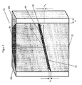
- FIG. 3 shows a perspective view of a first embodiment of a slit 50 according to the invention according to claim 3.
- the slit 50 comprises a first absorption element 52 having a first non-planar outer surface 54 and a second Absorption member 56 having a second non-planar outer surface 58. Between the two non-planar outer surfaces 54 and 58 is a gap 60.
- the absorption elements have a trapezoidal plan, which widens towards the radiation source; the lateral brackets 62a and 62b have a corresponding complementary shape.
- first non-planar outer surface 54 is in FIG. 3 drawn a Cartesian coordinate system, whose origin lies at the center of the first non-planar outer surface 54, the x- axis lies in the direction of the optical axis and the ⁇ -axis lies on the central axis through which all generators of the control surface on which the first not -plane outer surface 54 is, run.
- the imaging area is behind the aperture 50 in the direction of the positive x-axis.
- the height h 1 of the opening of the gap 60 at the front of the aperture 50 is greater than the height h 2 of the opening of the gap 60 at the back of the aperture 50.
- the height h 1 can be 3 mm and the height h 2 1 mm .
- the rear opening of the gap is steeper than the front opening of the gap due to the fan-shaped beam guide.
- the width d of the front side of a lateral support may for example be 10 to 25 mm.
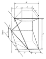
- FIG. 4 shows an exploded view of in FIG. 3 shown slit diaphragm according to the invention.
- two generators E 1 and E 2 of the control surface are drawn.
- the portion of the generatrix E 2 extending on the first non-planar outer surface 54 is highlighted for clarity.
- the distance in the y-direction, ie in the direction of the central axis, between the generatrices E 1 and E 2 decreases towards the imaging region.
- the distance between the generatrix of the control surface in the z-direction, and thus in each direction perpendicular to the optical axis also decreases towards the imaging region.
- FIG. 6 shows a perspective view of a second embodiment of a slit 70 according to the invention.
- the slit 70 comprises a first absorption element 72 with a first non-planar outer surface and a second absorption element 76th with a second non-planar outer surface.
- first absorption element 72 with a first non-planar outer surface
- second absorption element 76th with a second non-planar outer surface.
- the gap 80 is shown, not the complementary non-planar outer surfaces forming it, which are close together.
- a slit 70 ' according to the patent DE 10 2005 029 674 B4 drawn with a first absorption element 72 ', a second absorption element 76' and a gap 80 ', wherein both diaphragms have the same central axis and are described in the same Cartesian coordinate system whose ⁇ -axis lies on the common central axis.
- the absorption elements of the slit diaphragm of the second exemplary embodiment have a trapezoidal plan view.
- the lines of intersection of the gaps with the outer boundary surfaces of the respective slit are shown, namely in each case the two outermost generatrices E 3 and E 4 or E 3 'and E 4 ', the opening of the slit on the side of the slit diaphragm, O 1, facing the radiation source or O 1 ', and the opening of the gap on the imaging region side facing the slit, O 2 and O 2 '.
- the generatrices of the control surface, on which the first non-planar outer surface of the first absorption element of the slit diaphragm of the second embodiment lies, converge in the y-direction, ie in the direction of the central axis. Also, their z-coordinates approach each other in the range x ⁇ 0, in which the first non-planar outer surface lies.
- the distance between the generatrix of the control surface and the imaging region decreases in each direction perpendicular to the optical axis.
- the ⁇ -axis is outside the diaphragm body.
- the detector can be arranged in the vicinity of the gamma axis at a small distance from the slit diaphragm on a particularly small area.
- Such asymmetric design of the visor body has already been in the German patent application with the file number 10 2008 025 109.7-54 disclosed; However, in the present invention, not only the diaphragm body but also the (unlimited) control surface is asymmetrical with respect to the ⁇ -axis.
- FIG. 7 shows a perspective view of a third embodiment of a slit 90 according to the invention, in which, as in the German patent application with the file reference 10 2008 025 109.7-54 described in more detail, in addition to the gap 92, a further gap 94 is arranged, the shape of which results from an affine image of the shape of the gap 92.
- the affine mapping is a rotation about the central axis y about the angle ⁇ .
- the angle ⁇ influences both the intensity distribution in the image field as well as the width of the reproduced image; he can be chosen freely. If required, additional columns can be added.
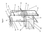
- FIG. 8 shows a perspective view of an inventive apparatus for beam milling a slit of cube-shaped raw material (semi-finished) with half-milled block.
- This device is suitable for manufacturing a slit diaphragm according to claim 3.
- the drawn Cartesian coordinate system is to be understood as a body-fixed on the workpiece 10 related; it corresponds to the in the Figures 3 . 4 and 6 drawn Cartesian coordinate systems.
- a first threaded shaft 16 is driven, which runs parallel to the ⁇ -axis.
- the first threaded shaft 16 has a portion 18 which is formed as a worm shaft.
- a holding arm 20 arranged parallel to the z axis is moved in a direction parallel to the ⁇ axis, whereby a second threaded shaft 22 connected to the holding arm 20 and arranged along the ⁇ axis and the workpiece 10 arranged thereon is moved linearly along the ⁇ -axis.
- the device comprises a third threaded shaft 40, which runs along the z-axis.
- the rotation of the three threaded shafts 16, 22 and 40 is synchronized, wherein the mechanical transmission via a gear system 24 is accomplished.
- the gear system 24 consists of three gears (front or bevel gears) 26, 28 and 42, which are mounted on the three threaded shafts 16, 22 and 40, a perpendicular to the ⁇ -axis worm shaft 30 and a further threaded shaft 44, the one area 46, which is formed as a screw shaft.
- the worm shaft 30 drives the gear 28 on the second threaded shaft 22, while also a transmission of Rotary movement between the mutually perpendicular gears 26, 32 takes place.
- the threaded shaft 44 drives the gear 42 on the third threaded shaft 40 via the formed as a screw shaft portion 46, while also a transmission of the rotational movement between the two gears 26, 38 takes place.
- the third threaded shaft 40 is fixed in space, and the entire device including the first and second threaded shaft is mounted so that it rotates upon rotation of the third threaded shaft 40 about this. Since the drawn coordinate system is to be understood as being body-fixed relative to the workpiece 10, the first threaded shaft 16 and the second threaded shaft 22 are still parallel to the ⁇ -axis after rotation about the third threaded shaft 40.
- a slit is cut into the workpiece 10 by a cutting jet 12.
- the cutting beam 12 extends in the illustrated position of the workpiece parallel to the x-axis and keeps this direction during the entire milling process at room, so does not participate in the rotation of the workpiece 10 and related to this body-fixed coordinate system. He follows the beam path through the produced aperture.
- the workpiece 10 is symmetrically inserted into the holder 36 a, 36 b to the in FIG. 3 illustrated inventive slit diaphragm of the first embodiment produce.
- the workpiece 10 is asymmetrical use, so that through the second threaded shaft 22 extending axis of rotation outside the diaphragm body comes to rest.
- a plurality of milling operations may be performed, wherein the workpiece 10 is to be inserted in a respective position corresponding to the gap to be milled.
- the workpiece 10 consists of a suitable collimator material, for example Densimet as mechanically processable tungsten alloy.
- a suitable collimator material for example Densimet as mechanically processable tungsten alloy.
- X-rays especially backscattered X-rays
- lead is in principle also suitable, but difficult to process mechanically. Conceivable would be the production in the casting process.
- a mold could be made with a blank of another suitable material.
- the device according to the invention and the method according to the invention are suitable for producing a slit diaphragm according to the invention, using the example of the device according to claim 9, in particular according to claim 10, the method according to claim 14, in particular according to claim 15, and the slit diaphragm according to claim 2, in particular according to Claim 3, shown.
- the beam paths cut by the device according to claim 9 and the method according to claim 14 are described in the above-introduced body-fixed coordinate system, ie the Cartesian coordinate system firmly connected to the workpiece.
- the origin of the coordinate system lies in the common intersection of the two axes of rotation and the cutting line of the cutting tool, and the y- axis points along the first axis of rotation.
- the x- axis and the z- axis lie so that they are in the in FIG. 8 represented, as a starting position considered position of the workpiece along the cutting line of the cutting tool or along the second axis of rotation.
- the rotation about the second axis of rotation must first be applied and then only the rotation about the body-fixed first axis of rotation and the displacement along the same.
- the slit diaphragm produced thus has a central axis in the y- axis, through which all cutting lines run, and thus has the additional feature of claim 2. If the two rotational movements and the translational motion are coupled linearly, there is a distance between the distance y 0 , which indicates the position of the intersection of the section line with the central axis, and the angles ⁇ and ⁇ , which are the polar angles of the direction vector (cos ⁇ cos ⁇ , sin ⁇ , cos ⁇ sin ⁇ ) with respect to the ⁇ -axis are a linear relationship.
- the slit diaphragm produced has the additional feature of claim 3.
- the direction vector of the section line forms the angle ⁇ / 2- ⁇ with the ⁇ -axis.
- the slit diaphragm thus produced also has the characterizing part of claim 1.
- the Gaussian curvature of the control surface of the slit diaphragm produced in this way results in a break with the counter - ⁇ cos 2 ⁇ , where ⁇ is the constant rate at which the angle ⁇ changes linearly along the central axis.
- the Gaussian curvature does not vanish anywhere in the subarea of the ruled surface used for imaging.
Landscapes
- Physics & Mathematics (AREA)
- Spectroscopy & Molecular Physics (AREA)
- Engineering & Computer Science (AREA)
- General Engineering & Computer Science (AREA)
- High Energy & Nuclear Physics (AREA)
- Apparatus For Radiation Diagnosis (AREA)
- Optical Elements Other Than Lenses (AREA)
Abstract
Description
Die Erfindung betrifft eine Schlitzblende, insbesondere eine asymmetrische Schlitzblende mit erweitertem Öffnungswinkel zur Abbildung strahlender und rückstreuender Objekte, gemäß dem Oberbegriff des Anspruchs 1, sowie eine Vorrichtung und ein Verfahren zur Herstellung derselben, gemäß den Oberbegriffen der Ansprüche 8 und 13.The invention relates to a slit diaphragm, in particular an asymmetrical slit diaphragm with extended opening angle for imaging radiating and backscattering objects, according to the preamble of
Häufig stellt sich das Problem, die Form verdeckter Quellen hochenergetischer, insbesondere ionisierender Strahlung jenseits des optischen Spektrums (insbesondere Röntgen- oder Gammastrahlung mit Photonenenergien über 20keV) mit unbekannter Struktur beziehungsweise räumlichem Aufbau zu ermitteln. Bei der Strahlenquelle kann es sich beispielsweise um den effektiven Brennfleck auf der Anode einer Röntgenröhre oder um flächig verteiltes strahlendes Material handeln. Letzteres können über einen Raum verteilte radioaktive Abfälle in einer Sammeltonne sein, wobei vermeintliche Diskrepanzen zwischen Deklarierung und tatsächlichem Inhalt zu klären sind. Weitere Beispiele für Strahlenquellen, deren Gestalt man abbilden möchte, sind Lagerstätten mit uranhaltigen Erzen oder kerntechnische Anlagen, bei denen es oftmals von Belang ist, nicht nur die Natur der Strahlung zu ermitteln, sondern auch die räumliche Struktur der Strahlenquellen zu bestimmen. Neben den genannten Quellen, welche die hochenergetische Strahlung direkt erzeugen, sind auch solche zu nennen, welche diese durch Röntgen- bzw. Gammarückstreuung erzeugen. Mit Hilfe der Abbildung rückgestreuter Strahlung können beispielsweise auch Objekte radiographisch untersucht werden, zu denen nur ein einseitiger Zugang möglich ist.Frequently the problem arises of determining the form of hidden sources of high-energy, in particular ionizing radiation beyond the optical spectrum (in particular X-ray or gamma radiation with photon energies above 20 keV) of unknown structure or spatial structure. The radiation source can be, for example, the effective focal spot on the anode of an x-ray tube or surface-distributed radiating material. The latter can be radioactive waste distributed over a room in a collecting bin, whereby alleged discrepancies between declaration and actual content must be clarified. Further examples of radiation sources whose shape one wishes to image are deposits with uranium-containing ores or nuclear facilities, in which it is often of importance not only to determine the nature of the radiation, but also to determine the spatial structure of the radiation sources. In addition to the sources mentioned, which generate the high-energy radiation directly, are also those that generate them by X-ray or Gammarückstreuung. With the help of the image of backscattered radiation, it is also possible, for example, to examine objects radiographically for which only one-sided access is possible.
Um die Gestalt solcher Strahlenquellen abzubilden, ist es naheliegend, das Prinzip einer Fotokamera anzuwenden. Es können dabei recht unterschiedliche Flächendetektoren eingesetzt werden: Filmmaterial, Speicherplatten, Speicherfolien, Halbleiter-Flachdetektoren, Vidicams, Bildverstärker oder Konverterfolien. Da solche Aufnahmen auch und vor allem in Umgebungen anfallen können, in die sich nach Möglichkeit Personen nicht hineinbegeben sollten, muss eine möglichst einfache Bedienbarkeit sichergestellt werden. Die einfachste Funktionalität und Handhabung wäre ein fernbedientes Platzieren eines entsprechenden Gerätes mit einer Rückholung nach der Expositionszeit ohne jegliche Betätigung irgendwelcher Bedienungselemente.To illustrate the shape of such radiation sources, it is obvious to apply the principle of a camera. Quite different area detectors can be used: film material, storage disks, storage foils, semiconductor flat detectors, vidicams, image intensifiers or converter foils. Since such recordings can also and especially occur in environments in which persons should not enter, if possible, the simplest operability must be ensured. The simplest functionality and handling would be to remotely place a corresponding device with retrieval after the exposure time without any operation of any controls.
Es ist bekannt, bei der Abbildung mit Hilfe energiereicher Strahlung das Lochkameraprinzip zu benutzen. Bei einer Lochkamera oder Camera obscura erzeugt ein kleines Loch auf einer Projektionsfläche ein Abbild von angestrahlten oder strahlenden Gegenständen. Dabei beschränkt der kleine Durchmesser der Blende die einfallenden Strahlenbündel auf einen kleinen Öffnungswinkel und verhindert so die vollständige Überlappung der Strahlen in der Abbildungsfläche. Strahlen von einem oberen Bereich eines strahlenden Körpers fallen auf den unteren Rand der Projektionsfläche, während umgekehrt Strahlen vom unteren Bereich auf den oberen Rand der Projektionsfläche abgebildet werden. Somit wird jeder Punkt des Gegenstandes als Scheibchen auf der Projektionsfläche abgebildet, so dass die Überlagerung der Scheibchenbilder ein Bild des strahlenden Körpers liefert, dessen Auflösung vom Abstand des strahlenden Körpers und der Form der Blende abhängt.It is known to use the Lochkameraprinzip when imaging with the help of high-energy radiation. In a pinhole camera or camera obscura , a small hole on a projection surface produces an image of illuminated or radiating objects. The small diameter of the diaphragm limits the incident beam to a small opening angle and thus prevents the complete overlap of the beams in the imaging surface. Radiation from an upper portion of a radiating body is incident on the lower edge of the projection surface while, conversely, rays are imaged from the lower portion to the upper edge of the projection surface. Thus, each point of the object is imaged as slices on the projection surface, so that the superimposition of the slice images provides an image of the radiating body whose resolution depends on the distance of the radiating body and the shape of the diaphragm.
Bei hochenergetischer Strahlung tritt das Problem auf, dass wegen ihres hohen Durchdringungsvermögens die Dicke des Materials für die Lochblende groß, das heißt im Verhältnis zur Halbwertsdicke der Intensität der zur Abbildung benutzten Strahlung gewählt werden muss. Deshalb wird die erreichbare Abbildungsgüte im Wesentlichen durch Blendendurchmesser und Materialdicke und -dichte bestimmt. Oft erhält man daher bestenfalls ein Schattenbild der eigentlichen Lochblende, wobei die Lochblende, die zur Abbildung dienen soll, aufgrund der Wanddicke zum Kollimator wird, der nur ein gradliniges Strahlenbündel passieren lässt. Deshalb wird oftmals die Blende in den Lochkameras trompetenförmig mit der engen Stelle zur Strahlenquelle gestaltet, um die abbildenden Eigenschaften nicht vollends zu verlieren. Bei energiereicher Strahlung liegt bei den aus dem Stand der Technik bekannten Lösungen aufgrund der erforderlichen Materialdicke eine erhebliche Abweichung vom idealen Lochkameraprinzip vor.The problem with high-energy radiation is that, because of its high permeability, the thickness of the material for the pinhole diaphragm must be large, that is to say in relation to the half-value thickness of the intensity of the radiation used for imaging. Therefore, the achievable image quality is essentially determined by aperture diameter and material thickness and density. Often, therefore, one obtains at best a shadow image of the actual pinhole, wherein the pinhole, which is to serve for imaging, due to the wall thickness becomes a collimator, which can pass only a straight-line beam. Therefore, the aperture in the hole cameras is often trumpet-shaped with the narrow spot to the radiation source designed so as not to lose the imaging properties completely. In the case of high-energy radiation, the solutions known from the prior art have a considerable deviation from the ideal hole-camera principle due to the required material thickness.
In der Patentschrift
Nachteilig ist an dieser Blende, dass der Kameraaufbau unhandlich und schwer ist; einschließlich der Abschirmung hat der Kameraaufbau typischerweise ein Gewicht von 200 bis 300 kg. Ein weiterer Nachteil liegt in der langen Expositionszeit; insbesondere bei der Abbildung rückstreuender Objekte kann aufgrund der geringen Intensität der Rückstreustrahlung eine Expositionszeit von mehr als einer halber Stunde erforderlich sein.The disadvantage of this panel that the camera body is unwieldy and heavy; including the shield, the camera assembly typically weighs 200 to 300 kg. Another disadvantage is the long exposure time; In particular when imaging backscattering objects, an exposure time of more than half an hour may be required due to the low intensity of the backscatter radiation.
Aufgabe der Erfindung ist es daher, eine Schlitzblende für eine Lochkamera anzugeben, welche gegenüber der in der Patentschrift
Erfindungsgemäß wird die Aufgabe mittels einer Schlitzblende, insbesondere einer asymmetrischen Schlitzblende mit erweitertem Öffnungswinkel zur Abbildung strahlender und rückstreuender Objekte, mit den im Anspruch 1 genannten Merkmalen gelöst.According to the invention the object is achieved by means of a slit diaphragm, in particular an asymmetrical slit diaphragm with extended opening angle for imaging radiating and backscattering objects, with the features mentioned in
Unter einem Absorptionselement ist hier ein Element zu verstehen, das zumindest einen Bereich aufweist, welcher die Strahlung zumindest teilweise absorbiert. Unter einem Spalt ist ein die Strahlung gering absorbierender Bereich zu verstehen. Er kann mit Luft oder einem anderen geeigneten Material gefüllt sein, welches die Strahlung weniger absorbiert als die die Strahlung zumindest teilweise absorbierenden Bereiche der Absorptionselemente, wobei das Material in Form eines separaten Einsatzstückes oder einer auf mindestens eine der nicht-ebenen Oberflächen aufgebrachten Beschichtung vorliegen kann.An absorption element here is to be understood as an element which has at least one region which at least partially absorbs the radiation. A gap is to be understood as meaning a region which absorbs the radiation to a small extent. It may be filled with air or other suitable material which absorbs the radiation less than the portions of the absorption elements at least partially absorbing the radiation, which material may be in the form of a separate insert or a coating applied to at least one of the non-planar surfaces ,
Unter einer Regelfläche (engl.: ruled surface) ist eine Fläche zu verstehen, bei der zu jedem Punkt auf der Fläche eine Gerade existiert, die vollständig in der Fläche liegt. Diese vollständig in der Fläche liegenden Geraden werden als die Erzeugenden der Regelfläche bezeichnet. Die gaußsche Krümmung einer Fläche in einem Punkt ist das Produkt ihrer beiden Hauptkrünimungen in dem Punkt; die Hauptkrümmungen der Fläche in einem Punkt sind der minimale Wert und der maximale Wert der Krümmungen aller Kurven, die sich durch Schneiden der Fläche mit einer die Flächennormale auf dem Punkt enthaltenden Ebene ergeben.A ruled surface is an area in which there is a straight line at every point on the surface that lies completely within the surface. These completely in-plane straight lines are referred to as the generators of the control surface. The Gaussian curvature of a surface at a point is the product of its two main features in the point; the principal curvatures of the area at a point are the minimum value and the maximum value of the curvatures of all curves resulting from intersecting the area with a plane containing the surface normal on the point.
Ein Beispiel einer Regelfläche ist die in der Patentschrift 
Um zu bestimmen, welche Regelflächen für eine Weiterentwicklung der in der Patentschrift
Als Bedingung für das Zustandekommen einer zweidimensionalen Abbildung ergibt sich somit, dass die Richtungsänderung beim Durchlaufen der Erzeugendenschar und die Richtungsänderung beim Drehen der Erzeugenden in der Tangentialebene voneinander linear unabhängig sein müssen; nur in diesem Fall führen diese beiden Richtungsänderungen zu einer zweidimensionalen Mannigfaltigkeit ungehindert oder nahezu ungehindert durchgelassener Strahlenbündel.As a condition for the realization of a two-dimensional mapping thus results that the change in direction when passing through the generatrix and the change in direction when rotating the generators in the tangent plane from each other must be linearly independent; only in this case, these two changes in direction lead to a two-dimensional manifold unhindered or almost unhindered transmitted beams.
Aus der Differentialgeometrie ist bekannt, dass die gaußsche Krümmung einer Regelfläche in einem Punkt genau dann verschwindet, wenn die Ableitung des Richtungsvektors der Erzeugenden und die auf der Erzeugenden senkrechte Tangente kolinear sind. Es folgt, dass genau dann eine zweidimensionale Abbildung erzeugt wird, wenn die gaußsche Krümmung der Regelfläche in dem verwendeten Teilbereich der Regelfläche nirgends verschwindet.It is known from differential geometry that the Gaussian curvature of a rule surface disappears at a point just when the derivative of the direction vector of the generator and the tangent perpendicular to the generator are collinear. It It follows that a two-dimensional image is produced if and only if the Gaussian curvature of the control surface does not disappear anywhere in the used subarea of the control surface.
Aus der Patentschrift
Um die Intensität auf der Abbildungsfläche zu erhöhen, ist der Kameraaufbau näher an das Objekt heranzuführen. Sowohl die Verkleinerung des Kameragehäuses als auch das nähere Heranbringen an das Objekt erfordern eine Vergrößerung des Blickwinkels. Dies wird umso mehr notwendig, wenn kleinflächige Flachdetektoren auf Halbleiterbasis eingesetzt werden sollen. Diese besitzen den Vorteil, nicht nur das Abbild direkt in digitale Signale zu wandeln, sondern auch mit sehr hoher Empfindlichkeit zur Verfügung zu stehen. Die Vergrößerung des Blickwinkels erfordert eine entsprechende Anpassung der Blendengeometrie, um eine fächerförmige Strahlenführung zu erreichen.In order to increase the intensity on the imaging surface, the camera structure is to be brought closer to the object. Both the downsizing of the camera body and the closer approach to the object require an enlargement of the viewing angle. This becomes all the more necessary when small-area semiconductor-based flat panel detectors are to be used. These have the advantage of not only converting the image directly into digital signals, but also being available with very high sensitivity. The enlargement of the viewing angle requires a corresponding adaptation of the diaphragm geometry in order to achieve a fan-shaped beam guidance.
Eine fächerförmige Strahlenführung wurde auch bei der in der Offenlegungsschrift
Wie die in der Patentschrift
Die erfindungsgemäße Blende ist darüber hinaus dadurch gekennzeichnet, dass der Abstand in einer Richtung senkrecht zu der optischen Achse zwischen den Erzeugenden der Regelfläche sich zum Abbildungsbereich hin verringert. Dadurch wird erreicht, dass die ungefähr entlang der Erzeugenden der Regelfläche einfallenden Strahlenbündel, die nahezu ungehindert durch die Blende treten, hinter der Blende konvergieren und in möglichst geringem Abstand von der Blende auf einen Abbildungsbereich treffen, der deutlich kleiner als der Blendenkörper sein kann. Bevorzugt ist, dass sich zumindest in einem Teilbereich der ersten nicht-ebenen Außenfläche der Abstand zwischen den Erzeugenden der Regelfläche zum Abbildungsbereich hin in jeder Richtung senkrecht zu der optischen Achse verringert. Dadurch wird erreicht, dass die ungefähr entlang der Erzeugenden der Regelfläche einfallenden Strahlenbündel besonders stark zum Abbildungsbereich hin konvergieren.The diaphragm according to the invention is further characterized in that the distance in a direction perpendicular to the optical axis between the generatrices of the control surface decreases towards the imaging region. This ensures that the approximately along the generatrix of the control surface incident beam converge almost unhindered through the aperture, converge behind the aperture and meet as close to the aperture on an imaging range, which can be significantly smaller than the diaphragm body. It is preferred that, at least in a partial region of the first non-planar outer surface, the distance between the generatrices of the control surface and the imaging region decreases in each direction perpendicular to the optical axis. It is thereby achieved that the radiation bundles incident approximately along the generatrix of the control surface converge particularly strongly towards the imaging region.
In bevorzugter Ausführung der Erfindung existiert eine Zentralachse, die jede der Erzeugenden der Regelfläche schneidet. Dadurch vereinfacht sich die Abbildungsvorschrift, und bei geeigneter Lage des Blendenkörpers kann der Bereich um die Zentralachse als Abbildungsbereich verwendet werden. Zum anderen wird dadurch erreicht, dass die Blende mit Hilfe einer Vorrichtung gemäß Anspruch 9 bzw. eines Verfahrens gemäß Anspruch 14 hergestellt werden kann.In a preferred embodiment of the invention, there is a central axis which intersects each of the generators of the control surface. As a result, the mapping rule is simplified, and with a suitable position of the diaphragm body, the area around the central axis can be used as the imaging area. On the other hand, it is achieved that the diaphragm can be produced by means of a device according to claim 9 or a method according to claim 14.
Besonders bevorzugt ist, dass die Polarwinkel der Richtungsvektoren der Erzeugenden der Regelfläche bezüglich der Zentralachse in linearem Zusammenhang mit dem Schnittpunkt der Erzeugenden der Regelfläche mit der Zentralachse stehen. Dadurch wird erreicht, dass die Abbildungsvorschrift näherungsweise linear ist und die Blende mit Hilfe einer Vorrichtung gemäß Anspruch 10 bzw. eines Verfahrens gemäß Anspruch 15 hergestellt werden kann.It is particularly preferred that the polar angles of the direction vectors of the generatrix of the control surface with respect to the central axis are linearly related to the intersection of the generatrix of the control surface with the central axis. This ensures that the mapping rule is approximately linear and the diaphragm can be produced by means of a device according to claim 10 or a method according to claim 15.
Unter einem linearen Zusammenhang mit dem Schnittpunkt der Erzeugenden der Regelfläche mit der Zentralachse ist dabei ein linearer Zusammenhang mit dem Abstand des Schnittpunkts der Erzeugenden der Regelfläche mit der Zentralachse von einem beliebigen festen Punkt auf der Zentralachse zu verstehen. Wenn die Polarwinkel der Richtungsvektoren der Erzeugenden der Regelfläche bezüglich der Zentralachse in einem solchen linearen Zusammenhang mit dem Schnittpunkt der Erzeugenden der Regelfläche mit der Zentralachse stehen und dieser lineare Zusammenhang jeweils kein konstanter Zusammenhang ist, d.h. beide Polarwinkel mit dem Schnittpunkt variieren, dann verschwindet die gaußsche Krümmung der Regelfläche nirgends. Somit ist die Menge aller Regelflächen, bei denen die Polarwinkel der Richtungsvektoren der Erzeugenden der Regelfläche bezüglich der Zentralachse in nicht konstantem linearen Zusammenhang mit dem Schnittpunkt der Erzeugenden der Regelfläche mit der Zentralachse stehen, eine Teilmenge der Regelflächen, deren gaußsche Krümmung nirgends verschwindet; d.h. das Merkmal, dass die Polarwinkel der Richtungsvektoren der Erzeugenden der Regelfläche bezüglich der Zentralachse in nicht konstantem linearem Zusammenhang mit dem Schnittpunkt der Erzeugenden der Regelfläche mit der Zentralachse stehen, führt zu einer erfindungsgemäßen Schlitzblende, ohne dass zusätzlich gefordert werden muss, dass die gaußsche Krümmung der Regelfläche nirgends verschwindet.Under a linear relationship with the intersection of the generatrix of the control surface with the central axis is to understand a linear relationship with the distance of the intersection of the generatrix of the control surface with the central axis of any fixed point on the central axis. If the polar angles of the direction vectors of the generatrix of the control surface with respect to the central axis are in such a linear relationship with the intersection of the generatrix of the control surface with the central axis and this linear relationship is not constant In other words, ie both polar angles vary with the point of intersection, then the Gaussian curvature of the control surface does not disappear anywhere. Thus, the set of all ruled surfaces in which the polar angles of the direction vectors of the generators of the ruled surface with respect to the central axis are not constantly linearly related to the intersection of the generatrices of the ruled surface with the central axis is a subset of the ruled surfaces whose Gaussian curvature does not disappear anywhere; that is, the feature that the polar angles of the direction vectors of the generatrix of the control surface with respect to the central axis in non-constant linear relationship with the intersection of the generatrix of the control surface with the central axis, resulting in a slit diaphragm according to the invention, without the additional requirement that the Gaussian curvature the ruled surface disappears nowhere.
In weiterer bevorzugter Ausführung der Erfindung liegt die Zentralachse außerhalb des Blendenkörpers. Dadurch wird erreicht, dass der Detektor in der Nähe der Zentralachse angeordnet werden kann, so dass sich auf möglichst kleiner Fläche ein Bild aufnehmen lässt.In a further preferred embodiment of the invention, the central axis is outside the diaphragm body. This ensures that the detector can be arranged in the vicinity of the central axis, so that an image can be recorded on the smallest possible area.
In weiterer bevorzugter Ausführung der Erfindung weisen die Absorptionselemente einen trapezförmigen Grundriss auf, der sich zur Strahlungsquelle hin erweitert. Dadurch wird erreicht, dass die Außenform der Absorptionselemente dem für die fächerförmige Strahlenführung verwendeten Bereich entspricht.In a further preferred embodiment of the invention, the absorption elements have a trapezoidal plan, which widens towards the radiation source. This ensures that the outer shape of the absorption elements corresponds to the area used for the fan-shaped beam guidance.
In weiterer bevorzugter Ausführung der Erfindung ist die Öffnung des Spalts auf der der Strahlungsquelle zugewandten Seite der Schlitzblende größer als die Öffnung des Spalts auf der dem Abbildungsbereich zugewandten Seite der Schlitzblende. Dadurch wird erreicht, dass die durch den Spalt tretenden Strahlenbündel auch in der Richtung senkrecht zum Spalt konvergieren.In a further preferred embodiment of the invention, the opening of the gap on the radiation source facing side of the slit is greater than the opening of the gap on the imaging region side facing the slit. This ensures that the beams passing through the gap also converge in the direction perpendicular to the gap.
In weiterer bevorzugter Ausführung der Erfindung umfasst die Schlitzblende zusätzlich zu dem einen Spalt mindestens einen weiteren Spalt, dessen Form jeweils im Wesentlichen durch eine affine Abbildung aus der Form des einen Spalts hervorgeht, wie in der deutschen Patentanmeldung mit dem Aktenzeichen 10 2008 025 109.7-54 näher beschrieben. Dadurch wird eine bessere Abbildungsqualität und/oder ein größerer Abbildungsbereich und/oder eine höhere Strahlenausbeute erzielt. Dabei ist eine affine Abbildung eine Abbildung des dreidimensionalen Raumes auf sich selbst, welche jede Gerade auf eine Gerade abbildet.In a further preferred embodiment of the invention, the slit diaphragm comprises, in addition to the one gap, at least one further gap, the shape of which in each case results essentially from an affine image from the shape of the one gap, as in German Patent Application No. 10 2008 025 109.7-54 described in more detail. As a result, a better imaging quality and / or a larger imaging range and / or a higher beam yield is achieved. An affine image is an image of the three-dimensional space on itself, which maps each straight line to a straight line.
In der europäischen Patentanmeldung
Erfindungsgemäß wird diese Aufgabe mittels einer Vorrichtung und eines Verfahrens zur Herstellung einer Schlitzblende gemäß den in Anspruch 8 bzw. Anspruch 13 genannten Merkmalen gelöst.According to the invention this object is achieved by means of a device and a method for producing a slit diaphragm according to the features mentioned in claim 8 or claim 13.
Wie die in der europäischen Patentanmeldung
Diese Lehre wird durch die vorliegende Erfindung dahingehend weiterentwickelt, dass die Mittel ferner geeignet sind, gleichzeitig mit der ersten Rotationsbewegung und der Translationsbewegung eine zweite Rotationsbewegung des Halteelements und der ersten Drehachse um eine zweite Drehachse zu bewirken, und die zweite Rotationsbewegung und die Translationsbewegung des Halteelements gekoppelt sind. Dadurch wird erreicht, dass der Abstand in Richtung der ersten Drehachse zwischen den geschnittenen Strahlengängen sich in der Richtung senkrecht zu den ersten und zweiten Drehachsen verringert.This teaching is further developed by the present invention in that the means are further adapted to effect a second rotational movement of the holding member and the first axis of rotation about a second axis of rotation simultaneously with the first rotational movement and the translational movement, and the second rotational movement and translational movement of the retaining element are coupled. It is thereby achieved that the distance in the direction of the first axis of rotation between the cut beam paths decreases in the direction perpendicular to the first and second axes of rotation.
Vorzugsweise weisen die erste Drehachse, die zweite Drehachse und die Linie, entlang derer das Schneidwerkzeug schneidet, einen gemeinsamen Schnittpunkt auf. Dadurch wird erreicht, dass die mittels der Vorrichtung hergestellte Schlitzblende das vorteilhafte zusätzliche Merkmal des Anspruchs 2 aufweist. Besonders bevorzugt ist, dass die zweite Drehachse senkrecht zur Schneidrichtung des Schneidwerkzeugs und senkrecht zur ersten Drehachse verläuft. Besonders bevorzugt ist ferner, dass die Translationsbewegung und die erste Rotationsbewegung linear gekoppelt sind und die Translationsbewegung und die zweite Rotationsbewegung linear gekoppelt sind. Eine solche lineare Kopplung ist mit besonders einfachen technischen Mitteln zu bewerkstelligen. Ferner wird dadurch erreicht, dass die mittels der Vorrichtung hergestellte Schlitzblende das vorteilhafte zusätzliche Merkmal des Anspruchs 3 aufweist.Preferably, the first axis of rotation, the second axis of rotation and the line along which the cutting tool cuts have a common point of intersection. Thereby it is achieved that the slit diaphragm produced by means of the device has the advantageous additional feature of claim 2. It is particularly preferred that the second axis of rotation is perpendicular to the cutting direction of the cutting tool and perpendicular to the first axis of rotation. It is further preferred that the translational movement and the first rotational movement are linearly coupled and the translational movement and the second rotational movement are linearly coupled. Such a linear coupling can be accomplished with particularly simple technical means. Furthermore, it is achieved that the slit diaphragm produced by means of the device has the advantageous additional feature of claim 3.
In bevorzugter Ausgestaltung der Erfindung ist vorgesehen, dass das Schneidwerkzeug unbeweglich angeordnet ist. Bevorzugt ist somit, dass das Schneidwerkzeug feststehend ist und das Werkstück daran herumgeführt wird. Ausgangspunkt dieser bevorzugten Ausführung ist, das Werkstück nicht in eine feste Halterung einzuspannen und das Werkzeug zu führen, sondern es umgekehrt kontrolliert beweglich um eine Fräse bzw. einen Schneidstrahl herumzuführen.In a preferred embodiment of the invention it is provided that the cutting tool is arranged immovably. It is thus preferred that the cutting tool is stationary and the workpiece is guided around it. The starting point of this preferred embodiment is not to clamp the workpiece in a fixed support and to guide the tool, but conversely to move it in a controlled manner around a milling cutter or a cutting jet.
Die Mittel können eine erste, eine zweite und eine dritte Gewindewelle umfassen, wobei die erste Gewindewelle parallel zu der ersten Drehachse verläuft, die zweite Gewindewelle auf der ersten Drehachse liegt und die dritte Gewindewelle auf der zweiten Drehachse liegt. Eine Rotationsbewegung der drei Gewindewellen kann durch ein Zahnradsystem gekoppelt sein.The means may comprise a first, a second and a third threaded shaft, wherein the first threaded shaft is parallel to the first axis of rotation, the second threaded shaft is located on the first axis of rotation and the third threaded shaft is located on the second axis of rotation. A rotational movement of the three threaded shafts may be coupled by a gear system.
Die erste Gewindewelle kann einen Bereich umfassen, welcher als Schneckenwelle ausgeformt ist, durch welchen ein Haltearm, mit welchem die zweite Gewindewelle verbunden ist, entlang der ersten Drehachse bewegbar ist.The first screw shaft may include a portion formed as a screw shaft through which a support arm to which the second screw shaft is connected is movable along the first rotation axis.
Wie in dem in der europäischen Patentanmeldung
Diese Lehre wird durch die vorliegende Erfindung dahingehend weiterentwickelt, dass gleichzeitig mit der ersten Rotationsbewegung und der Translationsbewegung eine zweite Rotationsbewegung des Werkstücks und der ersten Drehachse um eine zweite Drehachse ausgeführt wird und die zweite Rotationsbewegung und die Translationsbewegung des Werkstücks gekoppelt werden.This teaching is further developed by the present invention such that a second rotational movement of the workpiece and the first axis of rotation about a second axis of rotation is carried out simultaneously with the first rotational movement and the translation movement and the second rotational movement and the translational movement of the workpiece are coupled.
Vorzugsweise weisen die erste Drehachse, die zweite Drehachse und die Linie, entlang derer das Schneidwerkzeug schneidet, einen gemeinsamen Schnittpunkt auf. Dadurch wird erreicht, dass die mittels des Verfahrens hergestellte Schlitzblende das vorteilhafte zusätzliche Merkmal des Anspruchs 2 aufweist. Besonders bevorzugt ist, dass die zweite Drehachse senkrecht zur Schneidrichtung des Schneidwerkzeugs und senkrecht zur ersten Drehachse verläuft. Besonders bevorzugt ist ferner, dass die Translationsbewegung und die erste Rotationsbewegung linear gekoppelt werden und die Translationsbewegung und die zweite Rotationsbewegung linear gekoppelt werden. Eine solche lineare Kopplung ist mit besonders einfachen technischen Mitteln zu bewerkstelligen. Ferner wird dadurch erreicht, dass die mittels des Verfahrens hergestellte Schlitzblende das vorteilhafte zusätzliche Merkmal des Anspruchs 3 aufweist.Preferably, the first axis of rotation, the second axis of rotation and the line along which the cutting tool cuts have a common point of intersection. It is thereby achieved that the slit diaphragm produced by the method has the advantageous additional feature of claim 2. It is particularly preferred that the second axis of rotation is perpendicular to the cutting direction of the cutting tool and perpendicular to the first axis of rotation. It is also particularly preferred that the translational movement and the first rotational movement are linearly coupled and the translational movement and the second rotational movement are linearly coupled. Such a linear coupling can be accomplished with particularly simple technical means. Furthermore, it is achieved that the slit diaphragm produced by the method has the advantageous additional feature of claim 3.
Zum Schneiden des Schlitzes kann ein beliebiges aus dem Stand der Technik bekanntes Verfahren verwendet werden, darunter beispielsweise Fräsen, Feinfräsen, Präzisionsfräsen, Strahlen, Strahlfräsen oder Sägen.For cutting the slot, any method known in the art may be used, including, for example, milling, fine milling, precision milling, blasting, jet milling or sawing.
Die Erfindung wird nachfolgend in Ausführungsbeispielen anhand der zugehörigen Zeichnungen näher erläutert. Es zeigen:
Figur 1- eine bildgebende Einrichtung mit einer Blende;
- Figur 2
- (schematisch) eine Testanordnung;
- Figur 3
- eine Perspektivansicht eines ersten Ausführungsbeispiels einer erfindungs- gemäßen Schlitzblende;
- Figur 4
- eine Explosionsdarstellung der in
Figur 3 gezeigten erfindungsgemäßen Schlitzblende; - Figur 5
- eine Perspektivansicht des ersten Absorptionselements der in
Figur 3 gezeigten erfindungsgemäßen Schlitzblende; - Figur 6
- eine Perspektivansicht eines zweiten Ausführungsbeispiels einer erfindungsgemäßen Schlitzblende;
- Figur 7
- eine Perspektivansicht eines dritten Ausführungsbeispiels einer erfindungs- gemäßen Schlitzblende;
- Figur 8
- eine Perspektivansicht einer erfindungsgemäßen Vorrichtung zum Strahlfräsen einer Schlitzblende.
- FIG. 1
- an imaging device with a diaphragm;
- FIG. 2
- (schematically) a test arrangement;
- FIG. 3
- a perspective view of a first embodiment of a slit diaphragm according to the invention;
- FIG. 4
- an exploded view of in
FIG. 3 shown slit diaphragm according to the invention; - FIG. 5
- a perspective view of the first absorbent member of in
FIG. 3 shown slit diaphragm according to the invention; - FIG. 6
- a perspective view of a second embodiment of a slit diaphragm according to the invention;
- FIG. 7
- a perspective view of a third embodiment of a slit diaphragm according to the invention;
- FIG. 8
- a perspective view of a device according to the invention for beam milling a slit.
Zur Beschreibung der ersten nicht-ebenen Außenfläche 54 ist in
Die Höhe h1 der Öffnung des Spalts 60 an der Vorderseite der Blende 50 ist größer als die Höhe h2 der Öffnung des Spalts 60 an der Rückseite der Blende 50. Beispielsweise kann die Höhe h1 3 mm betragen und die Höhe h2 1 mm. Die hintere Öffnung des Spalts verläuft aufgrund der fächerförmigen Strahlenführung steiler als die vordere Öffnung des Spalts. Die Breite d der Vorderseite einer seitlichen Halterung kann beispielsweise 10 bis 25 mm betragen.The height h 1 of the opening of the
Wie bei der Schlitzblende des ersten Ausführungsbeispiels weisen die Absorptionselemente der Schlitzblende des zweiten Ausführungsbeispiels einen trapezförmigen Grundriss auf. Die Schnittlinien der Spalte mit den äußeren Grenzflächen der jeweiligen Schlitzblende sind eingezeichnet, nämlich jeweils die beiden äußersten Erzeugenden E3 und E4 bzw. E3' und E4', die Öffnung des Spalts auf der der Strahlungsquelle zugewandten Seite der Schlitzblende, O1 bzw. O1', und die Öffnung des Spalts auf der dem Abbildungsbereich zugewandten Seite der Schlitzblende, O2 bzw. O2'. Die Erzeugenden der Regelfläche, auf der die erste nicht-ebene Außenfläche des ersten Absorptionselements der Schlitzblende des zweiten Ausführungsbeispiels liegt, laufen in γ-Richtung, d.h. in Richtung der Zentralachse, aufeinander zu. Auch ihre z-Koordinaten nähern sich im Bereich x < 0, in dem die erste nicht-ebene Außenfläche liegt, einander an. In diesem Ausführungsbeispiel verringert sich somit auf der gesamten ersten nicht-ebenen Außenfläche der Abstand zwischen den Erzeugenden der Regelfläche zum Abbildungsbereich hin in jeder Richtung senkrecht zu der optischen Achse.As in the case of the slit diaphragm of the first exemplary embodiment, the absorption elements of the slit diaphragm of the second exemplary embodiment have a trapezoidal plan view. The lines of intersection of the gaps with the outer boundary surfaces of the respective slit are shown, namely in each case the two outermost generatrices E 3 and E 4 or E 3 'and E 4 ', the opening of the slit on the side of the slit diaphragm, O 1, facing the radiation source or O 1 ', and the opening of the gap on the imaging region side facing the slit, O 2 and O 2 '. The generatrices of the control surface, on which the first non-planar outer surface of the first absorption element of the slit diaphragm of the second embodiment lies, converge in the y-direction, ie in the direction of the central axis. Also, their z-coordinates approach each other in the range x <0, in which the first non-planar outer surface lies. Thus, in this embodiment, on the entire first non-planar outer surface, the distance between the generatrix of the control surface and the imaging region decreases in each direction perpendicular to the optical axis.
In diesem Ausführungsbeispiel liegt die γ-Achse außerhalb des Blendenkörpers. Dadurch kann in der Nähe der γ-Achse in geringem Abstand von der Schlitzblende auf besonders kleiner Fläche der Detektor angeordnet werden. Eine solche asymmetrische Gestaltung des Blendenkörpers wurde bereits in der deutschen Patentanmeldung mit dem Aktenzeichen
Mittels eines Motors (nicht gezeigt) wird eine erste Gewindewelle 16 angetrieben, welche parallel zur γ-Achse verläuft. Die erste Gewindewelle 16 weist einen Bereich 18 auf, der als Schneckenwelle ausgeformt ist. Durch mechanische Wechselwirkung mit dem Bereich 18 wird ein parallel zur z-Achse angeordneter Haltearm 20 in einer Richtung parallel zur γ-Achse fortbewegt, wodurch eine mit dem Haltearm 20 verbundene, entlang der γ-Achse angeordnete zweite Gewindewelle 22 und das darauf angeordnete Werkstück 10 linear entlang der γ-Achse bewegt wird. Ferner umfasst die Vorrichtung eine dritte Gewindewelle 40, welche entlang der z-Achse verläuft. Die Rotation der drei Gewindewellen 16, 22 und 40 erfolgt synchronisiert, wobei die mechanische Übertragung über ein Zahnradsystem 24 bewerkstelligt wird. Das Zahnradsystem 24 besteht aus drei Zahnrädern (Stirn- oder Kegelzahnräder) 26, 28 und 42, welche auf den drei Gewindewellen 16, 22 und 40 gelagert sind, einer senkrecht zur γ-Achse angeordneten Schneckenwelle 30 sowie einer weiteren Gewindewelle 44, die einen Bereich 46 aufweist, der als Schneckenwelle ausgeformt ist. Auf der Schneckenwelle 30 ist ein weiteres Zahnrad 32 gelagert, und auf der Gewindewelle 44 ist ein weiteres Zahnrad 38 gelagert. Die Schneckenwelle 30 treibt das Zahnrad 28 auf der zweiten Gewindewelle 22 an, während ebenfalls eine Übertragung der Drehbewegung zwischen den zueinander senkrecht angeordneten Zahnrädern 26, 32 erfolgt. In diesem Ausführungsbeispiel erfolgt an dieser Stelle eine Untersetzung der Geschwindigkeit von 2 : 1. Dadurch wird die Drehbewegung auf das Werkstück 10 übertragen, welches mittels einer Halterung 36a, 36b auf der zweiten Gewindewelle 22 angeordnet ist. Aufgrund der gleichzeitig ausgeführten linearen Abwärtsbewegung (entlang der γ-Achse) muss die Achse der zweiten Gewindewelle 22 mit der Halterung 36a, 36b des Werkstückes teleskopartig mit einem Rohr 34 so verbunden sein, dass die Drehung übertragen, die entlang der γ-Achse gerichtete Abwärtsbewegung gleichzeitig aber nicht behindert wird. Um einen Öffnungswinkel von γ = 60° zu überstreichen, während das Werkstück 10 über die Distanz d nach unten bewegt wird, muss bei dieser Anordnung das Zahnrad 28 einen Radius r von 3d/2π aufweisen, also von rund d/2.By means of a motor (not shown), a first threaded
Ferner treibt die Gewindewelle 44 über den als Schneckenwelle ausgeformten Teil 46 das Zahnrad 42 auf der dritten Gewindewelle 40 an, während ebenfalls eine Übertragung der Drehbewegung zwischen den beiden Zahnrädern 26, 38 erfolgt. Die dritte Gewindewelle 40 ist raumfest gelagert, und die gesamte Vorrichtung einschließlich der ersten und zweiten Gewindewelle ist so gelagert, dass sie sich bei einer Drehung der dritten Gewindewelle 40 um diese dreht. Da das eingezeichnete Koordinatensystem als körperfest auf das Werkstück 10 bezogenes aufzufassen ist, liegen die erste Gewindewelle 16 und die zweite Gewindewelle 22 nach einer Drehung um die dritte Gewindewelle 40 weiterhin parallel zur γ-Achse.Further, the threaded
Während der Rotationsbewegung des Werkstücks 10 um die zweite Gewindewelle 22 und die dritte Gewindewelle 40 und der gleichzeitig ausgeführten Translationsbewegung entlang der γ-Achse wird durch einen Schneidstrahl 12 ein Schlitz in das Werkstück 10 gefräst. Der Schneidstrahl 12 verläuft in der dargestellten Lage des Werkstücks parallel zur x-Achse und behält diese Richtung während des gesamten Fräsvorganges raumfest bei, nimmt also nicht an der Drehung des Werkstücks 10 und des auf dieses bezogenen körperfesten Koordinatensystems teil. Er folgt dabei dem Strahlengang durch die herzustellende Blende.During the rotational movement of the
In der Darstellung ist das Werkstück 10 symmetrisch in die Halterung 36a, 36b eingesetzt, um die in
Das Werkstück 10 besteht aus einem geeigneten Kollimatormaterial, beispielsweise Densimet als mechanisch verarbeitbare Wolframlegierung. Für Röntgenstrahlung, insbesondere rückgestreute Röntgenstrahlung, ist Blei prinzipiell auch geeignet, aber nur schwer mechanisch verarbeitbar. Denkbar wäre die Herstellung im Gussverfahren. Eine Form hierzu könnte mit einem Rohling aus einem anderen geeigneten Material gefertigt werden.The
Dass die erfindungsgemäße Vorrichtung und das erfindungsgemäße Verfahren geeignet sind, eine erfindungsgemäße Schlitzblende herzustellen, wird am Beispiel der Vorrichtung gemäß Anspruch 9, insbesondere gemäß Anspruch 10, des Verfahrens gemäß Anspruch 14, insbesondere gemäß Anspruch 15, und der Schlitzblende gemäß Anspruch 2, insbesondere gemäß Anspruch 3, gezeigt.The device according to the invention and the method according to the invention are suitable for producing a slit diaphragm according to the invention, using the example of the device according to claim 9, in particular according to
Die durch die Vorrichtung gemäß Anspruch 9 und das Verfahren gemäß Anspruch 14 geschnittenen Strahlengänge werden in dem oben eingeführten körperfesten, d.h. mit dem Werkstück fest verbundenen kartesischen Koordinatensystem beschrieben. Der Ursprung des Koordinatensystems liegt in dem gemeinsamen Schnittpunkt der beiden Drehachsen und der Schnittlinie des Schneidwerkzeugs, und die y-Achse zeigt entlang der ersten Drehachse. Die x-Achse und die z-Achse liegen so, dass sie in der in ![]()
![]()
Da die erste Drehachse sich mit dem Werkstück mitdreht und somit in dem körperfesten Koordinatensystem eine feste Richtung aufweist, während die zweite Drehachse bei einer Drehung um die erste Drehachse ihre Richtung in dem körperfesten Koordinatensystem ändert, ist zunächst die Drehung um die zweite Drehachse anzuwenden und dann erst die Drehung um die körperfeste erste Drehachse und die Verschiebung entlang derselben. Eine Drehung um einen Winkel ϑ um die in der Ausgangslage in z-Richtung liegende zweite Drehachse ergibt ![]()
![]()
Eine Drehung um einen Winkel ϕ um die körperfest in γ-Richtung liegende erste Drehachse ergibt dann ![]()
und eine Verschiebung um eine Strecke y0 entlang der körperfest in γ-Richtung liegenden ersten Drehachse führt schließlich auf 
![]()
and a displacement by a distance y 0 along the first axis of rotation lying body-fixed in the γ-direction finally leads
Die hergestellte Schlitzblende hat also in der y-Achse eine Zentralachse, durch die alle Schnittlinien verlaufen, und weist somit das zusätzliche Merkmal des Anspruchs 2 auf. Werden die beiden Rotationsbewegungen und die Translationsbewegung linear gekoppelt, so besteht zwischen der Strecke y 0, die die Lage des Schnittpunkts der Schnittlinie mit der Zentralachse angibt, und den Winkeln ϑ und ϕ, die die Polarwinkel des Richtungsvektors (cosϑ cosϕ,sinϑ, cosϑ sinϕ) bezüglich der γ-Achse sind, ein linearer Zusammenhang. Somit weist in diesem Fall die hergestellte Schlitzblende das zusätzliche Merkmal des Anspruchs 3 auf. Der Richtungsvektor der Schnittlinie bildet mit der γ-Achse den Winkel π/2-ϑ. Da dieser Winkel in linearem Zusammenhang mit der γ-Koordinate des Schnittpunkts mit der Zentralachse steht, nimmt (bei geeigneter Wahl des Drehsinns) der Abstand in γ-Richtung der Schnittlinien zum Abbildungsbereich hin ab. Somit weist die solchermaßen hergestellte Schlitzblende auch das Kennzeichen des Anspruchs 1 auf.The slit diaphragm produced thus has a central axis in the y- axis, through which all cutting lines run, and thus has the additional feature of claim 2. If the two rotational movements and the translational motion are coupled linearly, there is a distance between the distance y 0 , which indicates the position of the intersection of the section line with the central axis, and the angles θ and φ, which are the polar angles of the direction vector (cosθ cosφ, sinθ, cosθ sinφ ) with respect to the γ-axis are a linear relationship. Thus, in this case, the slit diaphragm produced has the additional feature of claim 3. The direction vector of the section line forms the angle π / 2-θ with the γ-axis. Since this angle is linearly related to the γ-coordinate of the point of intersection with the central axis, (with a suitable choice of the direction of rotation) the distance in the γ-direction of the cutting lines decreases towards the imaging region. Thus, the slit diaphragm thus produced also has the characterizing part of
Als gaußsche Krümmung der Regelfläche der solchermaßen hergestellten Schlitzblende ergibt sich ein Bruch mit dem Zähler - ϕ̇cos2ϑ, wobei ϕ̇ die konstante Rate ist, mit der sich der Winkel ϕ entlang der Zentralachse linear ändert. Die Winkel υ = ±π/2, bei denen diese Krümmung verschwindet, werden nicht verwendet, da der Strahlengang in diesem Fall entlang der Zentralachse verlaufen und nicht in Richtung des Abbildungsbereichs führen würde. Bei von Null verschiedener Änderungsrate ϕ̇ des Winkels ϕ verschwindet somit die gaußsche Krümmung nirgends in dem für die Abbildung verwendeten Teilbereich der Regelfläche.The Gaussian curvature of the control surface of the slit diaphragm produced in this way results in a break with the counter - φ̇cos 2 θ, where φ̇ is the constant rate at which the angle φ changes linearly along the central axis. The angles υ = ± π / 2, at which this curvature disappears, are not used, since the beam path in this case run along the central axis and would not lead in the direction of the imaging area. With a non-zero rate of change φ̇ of the angle φ, the Gaussian curvature does not vanish anywhere in the subarea of the ruled surface used for imaging.
- 1010
- Werkstückworkpiece
- 1212
- Schneidwerkzeugcutting tool
- 1616
- erste Gewindewellefirst thread shaft
- 1818
- Schneckenwelleworm shaft
- 2020
- Haltearmholding arm
- 2222
- zweite Gewindewellesecond threaded shaft
- 2424
- Zahnradsystemgear system
- 2626
- Zahnradgear
- 2828
- Zahnradgear
- 3030
- Schneckenwelleworm shaft
- 3232
- Zahnradgear
- 3434
- Rohrpipe
- 36a, b36a, b
- Halterungbracket
- 3838
- Zahnradgear
- 4040
- dritte Gewindewellethird thread shaft
- 4242
- Zahnradgear
- 4444
- Gewindewellethreaded shaft
- 4646
- Schneckenwelleworm shaft
- 5050
- Schlitzblendeslit
- 5252
- erstes Absorptionselementfirst absorption element
- 5454
- erste nicht-ebene Außenflächefirst non-flat outer surface
- 5656
- zweites Absorptionselementsecond absorption element
- 5858
- zweite nicht-ebene Außenflächesecond non-planar outer surface
- 6060
- Spaltgap
- 62a, b62a, b
- Halterungenbrackets
- 70, 70'70, 70 '
- Schlitzblendeslit
- 72, 72'72, 72 '
- erstes Absorptionselementfirst absorption element
- 76, 76'76, 76 '
- zweites Absorptionselementsecond absorption element
- 80, 80'80, 80 '
- Spaltgap
- 9090
- Schlitzblendeslit
- 90'90 '
- weiterer Blendenkörperfurther visor body
- 9292
- Spaltgap
- 9494
- weiterer Spaltanother gap
- 100100
- bildgebende EinrichtungImaging device
- 102102
- Strahlungsquelleradiation source
- 104104
- Strahlungradiation
- 106106
- Abbildungsbereichimaging area
- 108108
- Empfangseinheitreceiver unit
- 110110
- Blendecover
- 112112
- RöntgenröhreX-ray tube
- 114114
- Bleiwandlead wall
- 116116
- StreufilterLight diffuser
- 118118
- Testobjekttest object
- 120120
- Blendecover
- 122122
- Abschirmwandshielding
- 124124
- Detektordetector
- 126126
- Projektionsflächeprojection
- E1, E2 E 1 , E 2
- Erzeugendegenerating
- E3, E4, E3', E4'E 3 , E 4 , E 3 ', E 4 '
- äußerste Erzeugendeutmost generators
- O1, O2, O1', O2'O 1 , O 2 , O 1 ', O 2 '
- Öffnung des SpaltsOpening of the gap
Claims (15)
- Slit aperture (50, 70, 90), particularly for an imaging apparatus (100), which is suitable for delimiting radiation (104), more particularly high-energy radiation, emitted from a radiation source (102) and for directing it, according to the pinhole camera principle, onto an imaging region (106) along an optical axis (x),
wherein the slit aperture (50, 70, 90) comprises a first absorption element (52, 72), which has a first non-planar external face (54), of which at least one part lies on a ruled surface, the Gaussian curvature of which does not vanish anywhere in the part,
wherein the slit aperture (50, 70, 90) comprises a second absorption element (56, 76), which has a second non-planar external face (58), the surface contour of which is formed at least in part complementary to the non-planar external face (54) of the first absorption element (52, 72), and wherein the two absorption elements (52, 72; 56, 76) are or can be positioned such that there is a gap (60, 80, 92) between the two non-planar external faces (54, 58),
characterized in that
the distance in one direction (y) perpendicular to the optical axis (x) between the generatrices of the ruled surface reduces towards the imaging region (106). - Slit aperture (50, 70, 90) according to Claim 1,
characterized in that
there is a central axis (y) that intersects every generatrix of the ruled surface. - Slit aperture (50, 70, 90) according to Claim 2,
characterized in that
the polar angles of the directional vectors of the generatrices of the ruled surface are, in respect of the central axis (y), linearly related to the intersection of the generatrices of the ruled surface with the central axis (y). - Slit aperture (70, 90) according to Claim 2 or 3,
characterized in that
the central axis (y) is situated outside of the aperture frame. - Slit aperture (50, 70) according to one of the preceding claims,
characterized in that
the absorption elements (52, 72; 56, 76) have a trapezoidal outline, which expands towards the radiation source (102). - Slit aperture (50) according to one of the preceding claims,
characterized in that
the opening (h1) of the gap (60) on the side of the slit aperture (50) facing the radiation source (102) is greater than the opening (h2) of the gap (60) on the side of the slit aperture (50) facing the imaging region (106). - Slit aperture (90) according to one of the preceding claims,
characterized in that
the slit aperture (90), in addition to the one gap (92), comprises at least one further gap (94), the shape of which substantially emerges from an affine transformation of the shape of the one gap (92). - Device for producing a slit aperture (50, 70, 90), comprising
a cutting tool (12) that is suitable for cutting along a straight line, and
means that are suitable for bringing about a relative movement between the cutting tool (12) and a workpiece (10) such that the cutting tool (12) cuts the workpiece (10) along a line that corresponds to a beam path in the slit aperture (50, 70, 90) to be produced,
wherein
the cutting tool (12) is suitable for cutting along a first direction (x);
the means comprise a holding element (36a, 36b) onto which a workpiece (10) can be attached and which is mounted such that it can rotate about a first rotational axis (22);
the means are suitable for bringing about a first rotational movement of the holding element (36) about the first rotational axis (22) and, simultaneously, bringing about a translational movement of the holding element (36) along the first rotational axis (22); and
the first rotational movement and the translational movement of the holding element (36) are coupled,
characterized in that
the means are furthermore suitable for bringing about a second rotational movement of the holding element (36) and of the first rotational axis (22) about a second rotational axis (40), simultaneously with the first rotational movement and the translational movement, and
the second rotational movement and the translational movement of the holding element (36) are coupled. - Device according to Claim 8,
characterized in that
the second rotational axis (40) runs along a second direction (z) that is perpendicular to the cutting direction (x) of the cutting tool (12) and perpendicular to the first rotational axis (22) and
the first rotational axis (22), the second rotational axis (40) and the line along which the cutting tool (12) cuts, have a common point of intersection. - Device according to Claim 8 or 9,
characterized in that
the translational movement and the first rotational movement are coupled linearly and the translational movement and the second rotational movement are coupled linearly. - Device according to one of Claims 8 to 10,
characterized in that
the means comprise a first (16), a second (22) and a third (40) threaded shaft,
wherein the first threaded shaft (16) runs parallel to the first rotational axis (22), the second threaded shaft (22) lies on the first rotational axis (22) and the third threaded shaft (40) lies on the second rotational axis (40) and wherein a rotational movement of the three threaded shafts (16, 22, 40) is coupled by a gearwheel system (24). - Device according to Claim 11,
characterized in that
the first threaded shaft (16) comprises a region (18), which is embodied as a worm drive, by means of which a holding arm (20), to which the second threaded shaft (22) is connected, can be moved along the first rotational axis (22). - Method for producing a slit aperture,
wherein a relative movement between a cutting tool (12), which is suitable for cutting along a straight line, and a workpiece (10) is carried out such that the cutting tool (12) cuts the workpiece (10) along a line that corresponds to a beam path in the slit aperture to be produced;
the workpiece (10) is cut along an unchangeable first direction (x);
a first rotational movement of the workpiece (10) about a first rotational axis (22) and, simultaneously, a translational movement of the workpiece (10) along the first rotational axis (22) are carried out; and
the first rotational movement and the translational movement of the workpiece (10) are coupled,
characterized in that
a second rotational movement of the workpiece (10) and of the first rotational axis (22) about a second rotational axis (40) is carried out simultaneously with the first rotational movement and the translational movement and
the second rotational movement and the translational movement of the workpiece (10) are coupled. - Method according to Claim 13,
characterized in that
the second rotational axis (40) runs along a second direction (z) that is perpendicular to the cutting direction (x) of the cutting tool (12) and perpendicular to the first rotational axis (22) and
the first rotational axis (22), the second rotational axis (40) and the line along which the cutting tool (12) cuts, have a common point of intersection. - Method according to Claim 13 or 14,
characterized in that
the translational movement and the first rotational movement are coupled linearly and the translational movement and the second rotational movement are coupled linearly.
Priority Applications (3)
| Application Number | Priority Date | Filing Date | Title |
|---|---|---|---|
| EP09178329A EP2333786B1 (en) | 2009-12-08 | 2009-12-08 | Asymmetric slit diaphragm and device and method for producing same |
| AT09178329T ATE545935T1 (en) | 2009-12-08 | 2009-12-08 | ASYMMETRICAL SLIT PANEL AND DEVICE AND METHOD FOR PRODUCING THE SAME |
| PCT/EP2010/067273 WO2011069770A1 (en) | 2009-12-08 | 2010-11-11 | Asymmetrical slot aperture and device and method for the production thereof |
Applications Claiming Priority (1)
| Application Number | Priority Date | Filing Date | Title |
|---|---|---|---|
| EP09178329A EP2333786B1 (en) | 2009-12-08 | 2009-12-08 | Asymmetric slit diaphragm and device and method for producing same |
Publications (2)
| Publication Number | Publication Date |
|---|---|
| EP2333786A1 EP2333786A1 (en) | 2011-06-15 |
| EP2333786B1 true EP2333786B1 (en) | 2012-02-15 |
Family
ID=42103049
Family Applications (1)
| Application Number | Title | Priority Date | Filing Date |
|---|---|---|---|
| EP09178329A Not-in-force EP2333786B1 (en) | 2009-12-08 | 2009-12-08 | Asymmetric slit diaphragm and device and method for producing same |
Country Status (3)
| Country | Link |
|---|---|
| EP (1) | EP2333786B1 (en) |
| AT (1) | ATE545935T1 (en) |
| WO (1) | WO2011069770A1 (en) |
Families Citing this family (2)
| Publication number | Priority date | Publication date | Assignee | Title |
|---|---|---|---|---|
| CN104584137B (en) | 2012-07-05 | 2017-05-10 | 美国科技工程公司 | Variable angle collimator |
| DE102014103833B3 (en) * | 2014-03-20 | 2015-07-09 | Bundesrepublik Deutschland, Vertreten Durch Den Bundesminister Für Wirtschaft Und Energie, Dieser Vertreten Durch Den Präsidenten Der Bundesanstalt Für Materialforschung Und -Prüfung (Bam) | Slit diaphragm for radiography applications |
Family Cites Families (5)
| Publication number | Priority date | Publication date | Assignee | Title |
|---|---|---|---|---|
| DD240091A1 (en) | 1985-08-07 | 1986-10-15 | Akad Wissenschaften Ddr | LOCH CAMERA FOR ENORGY QUANTITY RADIATION |
| DE4000507A1 (en) | 1990-01-10 | 1991-07-11 | Philips Patentverwaltung | ARRANGEMENT FOR EXAMINING A TEST OBJECT WITH GAMMA OR X-RAY RADIATION |
| DE102005029674B4 (en) * | 2005-06-20 | 2008-08-21 | BAM Bundesanstalt für Materialforschung und -prüfung | Aperture for an imaging device |
| DE102005048519A1 (en) | 2005-10-06 | 2007-04-19 | BAM Bundesanstalt für Materialforschung und -prüfung | Focused aperture |
| DE102007057261B3 (en) | 2007-11-26 | 2009-08-06 | BAM Bundesanstalt für Materialforschung und -prüfung | Apparatus and method for producing slit diaphragms |
-
2009
- 2009-12-08 EP EP09178329A patent/EP2333786B1/en not_active Not-in-force
- 2009-12-08 AT AT09178329T patent/ATE545935T1/en active
-
2010
- 2010-11-11 WO PCT/EP2010/067273 patent/WO2011069770A1/en active Application Filing
Also Published As
| Publication number | Publication date |
|---|---|
| ATE545935T1 (en) | 2012-03-15 |
| WO2011069770A1 (en) | 2011-06-16 |
| EP2333786A1 (en) | 2011-06-15 |
Similar Documents
| Publication | Publication Date | Title |
|---|---|---|
| DE19619913C2 (en) | X-ray diagnostic device for tomosynthesis | |
| DE69218808T2 (en) | X-ray examination apparatus | |
| EP1749190B1 (en) | Method for measuring an object using a coordinate measuring machine including a computer tomograph | |
| DE102015224143B3 (en) | Method for adjusting the primary side of an X-ray diffractometer and associated X-ray diffractometer | |
| EP0807405A1 (en) | Method for producing tomosynthetic images | |
| EP2269042B1 (en) | X-ray computer tomograph and method for investigating a component by means of x-ray computer tomography | |
| DE102010062192B3 (en) | 2D collimator for a radiation detector and method of making such a 2D collimator | |
| EP1772874B1 (en) | Focal point oriented aperture | |
| EP1215482A2 (en) | Object examination device | |
| WO2008119555A1 (en) | Method and measuring arrangement for producing three-dimensional images of measuring objects by means of invasive radiation | |
| EP2175456A2 (en) | X-ray analysis instrument with mobile aperture window | |
| DE102005010077B4 (en) | Detector with a scintillator and imaging device, comprising such a detector | |
| WO2006136545A2 (en) | Diaphragm for an imaging device | |
| DE10337935A1 (en) | Device for recording structural data of an object | |
| DE102008048917A1 (en) | X-ray diffraction apparatus with a Debye-Scherrer optical system and X-ray diffraction measurement method for this apparatus | |
| DE2816218A1 (en) | IMPROVED SCANNER FOR COMPUTER TOMOGRAPHY | |
| DE2609925A1 (en) | ARRANGEMENT FOR DETERMINING THE SPATIAL DISTRIBUTION OF THE ABSORPTION OF A BODY | |
| DE102008025109B4 (en) | Aperture for an imaging device | |
| EP2333786B1 (en) | Asymmetric slit diaphragm and device and method for producing same | |
| DE2548531C2 (en) | ||
| DE102005009817B4 (en) | A shadow mask for an X-ray detector, computed tomography apparatus, comprising a shadow mask and method for adjusting a shadow mask | |
| EP3754328B1 (en) | Device for adjusting and changing beam catchers | |
| DE102014116595A1 (en) | Device and method for using multiple detectors in the dimensional measurement with a computed tomography sensor | |
| DE102011110109A1 (en) | Method for illuminating wheels by means of X-ray radiation and radiation protection cabin therefor | |
| DE102005011467B4 (en) | Adjustable focal length collimator, directed method and X-ray inspection system |
Legal Events
| Date | Code | Title | Description |
|---|---|---|---|
| PUAI | Public reference made under article 153(3) epc to a published international application that has entered the european phase |
Free format text: ORIGINAL CODE: 0009012 |
|
| 17P | Request for examination filed |
Effective date: 20100716 |
|
| AK | Designated contracting states |
Kind code of ref document: A1 Designated state(s): AT BE BG CH CY CZ DE DK EE ES FI FR GB GR HR HU IE IS IT LI LT LU LV MC MK MT NL NO PL PT RO SE SI SK SM TR |
|
| AX | Request for extension of the european patent |
Extension state: AL BA RS |
|
| GRAP | Despatch of communication of intention to grant a patent |
Free format text: ORIGINAL CODE: EPIDOSNIGR1 |
|
| RIC1 | Information provided on ipc code assigned before grant |
Ipc: G21K 1/02 20060101AFI20110715BHEP |
|
| GRAS | Grant fee paid |
Free format text: ORIGINAL CODE: EPIDOSNIGR3 |
|
| GRAA | (expected) grant |
Free format text: ORIGINAL CODE: 0009210 |
|
| AK | Designated contracting states |
Kind code of ref document: B1 Designated state(s): AT BE BG CH CY CZ DE DK EE ES FI FR GB GR HR HU IE IS IT LI LT LU LV MC MK MT NL NO PL PT RO SE SI SK SM TR |
|
| REG | Reference to a national code |
Ref country code: GB Ref legal event code: FG4D Free format text: NOT ENGLISH Ref country code: CH Ref legal event code: EP |
|
| REG | Reference to a national code |
Ref country code: IE Ref legal event code: FG4D Free format text: LANGUAGE OF EP DOCUMENT: GERMAN |
|
| REG | Reference to a national code |
Ref country code: AT Ref legal event code: REF Ref document number: 545935 Country of ref document: AT Kind code of ref document: T Effective date: 20120315 |
|
| REG | Reference to a national code |
Ref country code: DE Ref legal event code: R096 Ref document number: 502009002797 Country of ref document: DE Effective date: 20120419 |
|
| REG | Reference to a national code |
Ref country code: NL Ref legal event code: VDEP Effective date: 20120215 |
|
| LTIE | Lt: invalidation of european patent or patent extension |
Effective date: 20120215 |
|
| REG | Reference to a national code |
Ref country code: DE Ref legal event code: R082 Ref document number: 502009002797 Country of ref document: DE Representative=s name: ZIMMERMANN & PARTNER, DE Ref country code: DE Ref legal event code: R082 Ref document number: 502009002797 Country of ref document: DE Representative=s name: ZIMMERMANN & PARTNER PATENTANWAELTE MBB, DE |
|
| PG25 | Lapsed in a contracting state [announced via postgrant information from national office to epo] |
Ref country code: HR Free format text: LAPSE BECAUSE OF FAILURE TO SUBMIT A TRANSLATION OF THE DESCRIPTION OR TO PAY THE FEE WITHIN THE PRESCRIBED TIME-LIMIT Effective date: 20120215 Ref country code: LT Free format text: LAPSE BECAUSE OF FAILURE TO SUBMIT A TRANSLATION OF THE DESCRIPTION OR TO PAY THE FEE WITHIN THE PRESCRIBED TIME-LIMIT Effective date: 20120215 Ref country code: IS Free format text: LAPSE BECAUSE OF FAILURE TO SUBMIT A TRANSLATION OF THE DESCRIPTION OR TO PAY THE FEE WITHIN THE PRESCRIBED TIME-LIMIT Effective date: 20120615 Ref country code: NO Free format text: LAPSE BECAUSE OF FAILURE TO SUBMIT A TRANSLATION OF THE DESCRIPTION OR TO PAY THE FEE WITHIN THE PRESCRIBED TIME-LIMIT Effective date: 20120515 Ref country code: NL Free format text: LAPSE BECAUSE OF FAILURE TO SUBMIT A TRANSLATION OF THE DESCRIPTION OR TO PAY THE FEE WITHIN THE PRESCRIBED TIME-LIMIT Effective date: 20120215 |
|
| PG25 | Lapsed in a contracting state [announced via postgrant information from national office to epo] |
Ref country code: PT Free format text: LAPSE BECAUSE OF FAILURE TO SUBMIT A TRANSLATION OF THE DESCRIPTION OR TO PAY THE FEE WITHIN THE PRESCRIBED TIME-LIMIT Effective date: 20120615 Ref country code: FI Free format text: LAPSE BECAUSE OF FAILURE TO SUBMIT A TRANSLATION OF THE DESCRIPTION OR TO PAY THE FEE WITHIN THE PRESCRIBED TIME-LIMIT Effective date: 20120215 Ref country code: LV Free format text: LAPSE BECAUSE OF FAILURE TO SUBMIT A TRANSLATION OF THE DESCRIPTION OR TO PAY THE FEE WITHIN THE PRESCRIBED TIME-LIMIT Effective date: 20120215 Ref country code: GR Free format text: LAPSE BECAUSE OF FAILURE TO SUBMIT A TRANSLATION OF THE DESCRIPTION OR TO PAY THE FEE WITHIN THE PRESCRIBED TIME-LIMIT Effective date: 20120516 Ref country code: PL Free format text: LAPSE BECAUSE OF FAILURE TO SUBMIT A TRANSLATION OF THE DESCRIPTION OR TO PAY THE FEE WITHIN THE PRESCRIBED TIME-LIMIT Effective date: 20120215 |
|
| REG | Reference to a national code |
Ref country code: IE Ref legal event code: FD4D |
|
| PG25 | Lapsed in a contracting state [announced via postgrant information from national office to epo] |
Ref country code: CY Free format text: LAPSE BECAUSE OF FAILURE TO SUBMIT A TRANSLATION OF THE DESCRIPTION OR TO PAY THE FEE WITHIN THE PRESCRIBED TIME-LIMIT Effective date: 20120215 |
|
| PG25 | Lapsed in a contracting state [announced via postgrant information from national office to epo] |
Ref country code: EE Free format text: LAPSE BECAUSE OF FAILURE TO SUBMIT A TRANSLATION OF THE DESCRIPTION OR TO PAY THE FEE WITHIN THE PRESCRIBED TIME-LIMIT Effective date: 20120215 Ref country code: RO Free format text: LAPSE BECAUSE OF FAILURE TO SUBMIT A TRANSLATION OF THE DESCRIPTION OR TO PAY THE FEE WITHIN THE PRESCRIBED TIME-LIMIT Effective date: 20120215 Ref country code: IE Free format text: LAPSE BECAUSE OF FAILURE TO SUBMIT A TRANSLATION OF THE DESCRIPTION OR TO PAY THE FEE WITHIN THE PRESCRIBED TIME-LIMIT Effective date: 20120215 Ref country code: DK Free format text: LAPSE BECAUSE OF FAILURE TO SUBMIT A TRANSLATION OF THE DESCRIPTION OR TO PAY THE FEE WITHIN THE PRESCRIBED TIME-LIMIT Effective date: 20120215 Ref country code: SE Free format text: LAPSE BECAUSE OF FAILURE TO SUBMIT A TRANSLATION OF THE DESCRIPTION OR TO PAY THE FEE WITHIN THE PRESCRIBED TIME-LIMIT Effective date: 20120215 Ref country code: CZ Free format text: LAPSE BECAUSE OF FAILURE TO SUBMIT A TRANSLATION OF THE DESCRIPTION OR TO PAY THE FEE WITHIN THE PRESCRIBED TIME-LIMIT Effective date: 20120215 Ref country code: SI Free format text: LAPSE BECAUSE OF FAILURE TO SUBMIT A TRANSLATION OF THE DESCRIPTION OR TO PAY THE FEE WITHIN THE PRESCRIBED TIME-LIMIT Effective date: 20120215 |
|
| PG25 | Lapsed in a contracting state [announced via postgrant information from national office to epo] |
Ref country code: IT Free format text: LAPSE BECAUSE OF FAILURE TO SUBMIT A TRANSLATION OF THE DESCRIPTION OR TO PAY THE FEE WITHIN THE PRESCRIBED TIME-LIMIT Effective date: 20120215 Ref country code: SK Free format text: LAPSE BECAUSE OF FAILURE TO SUBMIT A TRANSLATION OF THE DESCRIPTION OR TO PAY THE FEE WITHIN THE PRESCRIBED TIME-LIMIT Effective date: 20120215 |
|
| PLBE | No opposition filed within time limit |
Free format text: ORIGINAL CODE: 0009261 |
|
| STAA | Information on the status of an ep patent application or granted ep patent |
Free format text: STATUS: NO OPPOSITION FILED WITHIN TIME LIMIT |
|
| 26N | No opposition filed |
Effective date: 20121116 |
|
| REG | Reference to a national code |
Ref country code: DE Ref legal event code: R097 Ref document number: 502009002797 Country of ref document: DE Effective date: 20121116 |
|
| PG25 | Lapsed in a contracting state [announced via postgrant information from national office to epo] |
Ref country code: ES Free format text: LAPSE BECAUSE OF FAILURE TO SUBMIT A TRANSLATION OF THE DESCRIPTION OR TO PAY THE FEE WITHIN THE PRESCRIBED TIME-LIMIT Effective date: 20120526 |
|
| BERE | Be: lapsed |
Owner name: BAM BUNDESANSTALT FUR MATERIALFORSCHUNG UND -PRUF Effective date: 20121231 |
|
| PG25 | Lapsed in a contracting state [announced via postgrant information from national office to epo] |
Ref country code: BG Free format text: LAPSE BECAUSE OF FAILURE TO SUBMIT A TRANSLATION OF THE DESCRIPTION OR TO PAY THE FEE WITHIN THE PRESCRIBED TIME-LIMIT Effective date: 20120515 Ref country code: MC Free format text: LAPSE BECAUSE OF NON-PAYMENT OF DUE FEES Effective date: 20121231 |
|
| REG | Reference to a national code |
Ref country code: FR Ref legal event code: ST Effective date: 20130830 |
|
| PG25 | Lapsed in a contracting state [announced via postgrant information from national office to epo] |
Ref country code: BE Free format text: LAPSE BECAUSE OF NON-PAYMENT OF DUE FEES Effective date: 20121231 |
|
| PG25 | Lapsed in a contracting state [announced via postgrant information from national office to epo] |
Ref country code: FR Free format text: LAPSE BECAUSE OF NON-PAYMENT OF DUE FEES Effective date: 20130102 Ref country code: MT Free format text: LAPSE BECAUSE OF FAILURE TO SUBMIT A TRANSLATION OF THE DESCRIPTION OR TO PAY THE FEE WITHIN THE PRESCRIBED TIME-LIMIT Effective date: 20120215 |
|
| PG25 | Lapsed in a contracting state [announced via postgrant information from national office to epo] |
Ref country code: TR Free format text: LAPSE BECAUSE OF FAILURE TO SUBMIT A TRANSLATION OF THE DESCRIPTION OR TO PAY THE FEE WITHIN THE PRESCRIBED TIME-LIMIT Effective date: 20120215 |
|
| PG25 | Lapsed in a contracting state [announced via postgrant information from national office to epo] |
Ref country code: LU Free format text: LAPSE BECAUSE OF NON-PAYMENT OF DUE FEES Effective date: 20121208 Ref country code: SM Free format text: LAPSE BECAUSE OF FAILURE TO SUBMIT A TRANSLATION OF THE DESCRIPTION OR TO PAY THE FEE WITHIN THE PRESCRIBED TIME-LIMIT Effective date: 20120215 |
|
| PG25 | Lapsed in a contracting state [announced via postgrant information from national office to epo] |
Ref country code: HU Free format text: LAPSE BECAUSE OF FAILURE TO SUBMIT A TRANSLATION OF THE DESCRIPTION OR TO PAY THE FEE WITHIN THE PRESCRIBED TIME-LIMIT Effective date: 20091208 |
|
| REG | Reference to a national code |
Ref country code: CH Ref legal event code: PL |
|
| GBPC | Gb: european patent ceased through non-payment of renewal fee |
Effective date: 20131208 |
|
| PG25 | Lapsed in a contracting state [announced via postgrant information from national office to epo] |
Ref country code: CH Free format text: LAPSE BECAUSE OF NON-PAYMENT OF DUE FEES Effective date: 20131231 Ref country code: LI Free format text: LAPSE BECAUSE OF NON-PAYMENT OF DUE FEES Effective date: 20131231 |
|
| PG25 | Lapsed in a contracting state [announced via postgrant information from national office to epo] |
Ref country code: GB Free format text: LAPSE BECAUSE OF NON-PAYMENT OF DUE FEES Effective date: 20131208 |
|
| PGFP | Annual fee paid to national office [announced via postgrant information from national office to epo] |
Ref country code: DE Payment date: 20141230 Year of fee payment: 6 |
|
| PG25 | Lapsed in a contracting state [announced via postgrant information from national office to epo] |
Ref country code: MK Free format text: LAPSE BECAUSE OF FAILURE TO SUBMIT A TRANSLATION OF THE DESCRIPTION OR TO PAY THE FEE WITHIN THE PRESCRIBED TIME-LIMIT Effective date: 20120215 |
|
| REG | Reference to a national code |
Ref country code: AT Ref legal event code: MM01 Ref document number: 545935 Country of ref document: AT Kind code of ref document: T Effective date: 20141208 |
|
| PG25 | Lapsed in a contracting state [announced via postgrant information from national office to epo] |
Ref country code: AT Free format text: LAPSE BECAUSE OF NON-PAYMENT OF DUE FEES Effective date: 20141208 |
|
| REG | Reference to a national code |
Ref country code: DE Ref legal event code: R119 Ref document number: 502009002797 Country of ref document: DE |
|
| PG25 | Lapsed in a contracting state [announced via postgrant information from national office to epo] |
Ref country code: DE Free format text: LAPSE BECAUSE OF NON-PAYMENT OF DUE FEES Effective date: 20160701 |