EP2120803B1 - Stent delivery system - Google Patents
Stent delivery system Download PDFInfo
- Publication number
- EP2120803B1 EP2120803B1 EP07869825.5A EP07869825A EP2120803B1 EP 2120803 B1 EP2120803 B1 EP 2120803B1 EP 07869825 A EP07869825 A EP 07869825A EP 2120803 B1 EP2120803 B1 EP 2120803B1
- Authority
- EP
- European Patent Office
- Prior art keywords
- lumen
- proximal
- segment
- distal
- catheter shaft
- Prior art date
- Legal status (The legal status is an assumption and is not a legal conclusion. Google has not performed a legal analysis and makes no representation as to the accuracy of the status listed.)
- Active
Links
- 238000000034 method Methods 0.000 claims description 11
- 229920000642 polymer Polymers 0.000 claims description 5
- 230000008878 coupling Effects 0.000 description 18
- 238000010168 coupling process Methods 0.000 description 18
- 238000005859 coupling reaction Methods 0.000 description 18
- 239000000463 material Substances 0.000 description 15
- 239000007769 metal material Substances 0.000 description 6
- 230000014759 maintenance of location Effects 0.000 description 5
- 238000004891 communication Methods 0.000 description 4
- 238000001125 extrusion Methods 0.000 description 4
- 239000012530 fluid Substances 0.000 description 4
- -1 polyethylene Polymers 0.000 description 3
- 230000000717 retained effect Effects 0.000 description 3
- 230000002792 vascular Effects 0.000 description 3
- 229910045601 alloy Inorganic materials 0.000 description 2
- 239000000956 alloy Substances 0.000 description 2
- 230000000712 assembly Effects 0.000 description 2
- 238000000429 assembly Methods 0.000 description 2
- 230000002496 gastric effect Effects 0.000 description 2
- 239000003550 marker Substances 0.000 description 2
- 239000000203 mixture Substances 0.000 description 2
- 238000012986 modification Methods 0.000 description 2
- 230000004048 modification Effects 0.000 description 2
- 229910001000 nickel titanium Inorganic materials 0.000 description 2
- 238000003466 welding Methods 0.000 description 2
- 229910000640 Fe alloy Inorganic materials 0.000 description 1
- 208000031481 Pathologic Constriction Diseases 0.000 description 1
- 239000004952 Polyamide Substances 0.000 description 1
- 229920002614 Polyether block amide Polymers 0.000 description 1
- 239000004698 Polyethylene Substances 0.000 description 1
- 239000004743 Polypropylene Substances 0.000 description 1
- HZEWFHLRYVTOIW-UHFFFAOYSA-N [Ti].[Ni] Chemical compound [Ti].[Ni] HZEWFHLRYVTOIW-UHFFFAOYSA-N 0.000 description 1
- 238000004026 adhesive bonding Methods 0.000 description 1
- 238000013459 approach Methods 0.000 description 1
- 210000003445 biliary tract Anatomy 0.000 description 1
- 230000015572 biosynthetic process Effects 0.000 description 1
- 238000005219 brazing Methods 0.000 description 1
- 239000000788 chromium alloy Substances 0.000 description 1
- BIJOYKCOMBZXAE-UHFFFAOYSA-N chromium iron nickel Chemical compound [Cr].[Fe].[Ni] BIJOYKCOMBZXAE-UHFFFAOYSA-N 0.000 description 1
- 230000006835 compression Effects 0.000 description 1
- 238000007906 compression Methods 0.000 description 1
- 229920001577 copolymer Polymers 0.000 description 1
- 238000013461 design Methods 0.000 description 1
- 238000006073 displacement reaction Methods 0.000 description 1
- 239000000835 fiber Substances 0.000 description 1
- 230000006870 function Effects 0.000 description 1
- 230000004927 fusion Effects 0.000 description 1
- 238000003780 insertion Methods 0.000 description 1
- 230000037431 insertion Effects 0.000 description 1
- 230000007774 longterm Effects 0.000 description 1
- 229910052751 metal Inorganic materials 0.000 description 1
- 239000002184 metal Substances 0.000 description 1
- 150000002739 metals Chemical class 0.000 description 1
- 238000013508 migration Methods 0.000 description 1
- 230000005012 migration Effects 0.000 description 1
- HLXZNVUGXRDIFK-UHFFFAOYSA-N nickel titanium Chemical compound [Ti].[Ti].[Ti].[Ti].[Ti].[Ti].[Ti].[Ti].[Ti].[Ti].[Ti].[Ni].[Ni].[Ni].[Ni].[Ni].[Ni].[Ni].[Ni].[Ni].[Ni].[Ni].[Ni].[Ni].[Ni] HLXZNVUGXRDIFK-UHFFFAOYSA-N 0.000 description 1
- 229910000623 nickel–chromium alloy Inorganic materials 0.000 description 1
- 229920002647 polyamide Polymers 0.000 description 1
- 229920000573 polyethylene Polymers 0.000 description 1
- 229920001155 polypropylene Polymers 0.000 description 1
- 229920001343 polytetrafluoroethylene Polymers 0.000 description 1
- 239000004810 polytetrafluoroethylene Substances 0.000 description 1
- 229920002635 polyurethane Polymers 0.000 description 1
- 239000004814 polyurethane Substances 0.000 description 1
- 229920000915 polyvinyl chloride Polymers 0.000 description 1
- 239000004800 polyvinyl chloride Substances 0.000 description 1
- 230000008569 process Effects 0.000 description 1
- 230000002787 reinforcement Effects 0.000 description 1
- 238000005476 soldering Methods 0.000 description 1
- 239000007787 solid Substances 0.000 description 1
- 239000010935 stainless steel Substances 0.000 description 1
- 229910001220 stainless steel Inorganic materials 0.000 description 1
- 230000036262 stenosis Effects 0.000 description 1
- 208000037804 stenosis Diseases 0.000 description 1
- WFKWXMTUELFFGS-UHFFFAOYSA-N tungsten Chemical compound [W] WFKWXMTUELFFGS-UHFFFAOYSA-N 0.000 description 1
- 229910052721 tungsten Inorganic materials 0.000 description 1
- 239000010937 tungsten Substances 0.000 description 1
- 210000000626 ureter Anatomy 0.000 description 1
Images


Classifications
-
- A—HUMAN NECESSITIES
- A61—MEDICAL OR VETERINARY SCIENCE; HYGIENE
- A61F—FILTERS IMPLANTABLE INTO BLOOD VESSELS; PROSTHESES; DEVICES PROVIDING PATENCY TO, OR PREVENTING COLLAPSING OF, TUBULAR STRUCTURES OF THE BODY, e.g. STENTS; ORTHOPAEDIC, NURSING OR CONTRACEPTIVE DEVICES; FOMENTATION; TREATMENT OR PROTECTION OF EYES OR EARS; BANDAGES, DRESSINGS OR ABSORBENT PADS; FIRST-AID KITS
- A61F2/00—Filters implantable into blood vessels; Prostheses, i.e. artificial substitutes or replacements for parts of the body; Appliances for connecting them with the body; Devices providing patency to, or preventing collapsing of, tubular structures of the body, e.g. stents
- A61F2/95—Instruments specially adapted for placement or removal of stents or stent-grafts
-
- A—HUMAN NECESSITIES
- A61—MEDICAL OR VETERINARY SCIENCE; HYGIENE
- A61F—FILTERS IMPLANTABLE INTO BLOOD VESSELS; PROSTHESES; DEVICES PROVIDING PATENCY TO, OR PREVENTING COLLAPSING OF, TUBULAR STRUCTURES OF THE BODY, e.g. STENTS; ORTHOPAEDIC, NURSING OR CONTRACEPTIVE DEVICES; FOMENTATION; TREATMENT OR PROTECTION OF EYES OR EARS; BANDAGES, DRESSINGS OR ABSORBENT PADS; FIRST-AID KITS
- A61F2/00—Filters implantable into blood vessels; Prostheses, i.e. artificial substitutes or replacements for parts of the body; Appliances for connecting them with the body; Devices providing patency to, or preventing collapsing of, tubular structures of the body, e.g. stents
- A61F2/02—Prostheses implantable into the body
- A61F2/04—Hollow or tubular parts of organs, e.g. bladders, tracheae, bronchi or bile ducts
- A61F2002/041—Bile ducts
-
- A—HUMAN NECESSITIES
- A61—MEDICAL OR VETERINARY SCIENCE; HYGIENE
- A61M—DEVICES FOR INTRODUCING MEDIA INTO, OR ONTO, THE BODY; DEVICES FOR TRANSDUCING BODY MEDIA OR FOR TAKING MEDIA FROM THE BODY; DEVICES FOR PRODUCING OR ENDING SLEEP OR STUPOR
- A61M25/00—Catheters; Hollow probes
- A61M25/0021—Catheters; Hollow probes characterised by the form of the tubing
- A61M25/0023—Catheters; Hollow probes characterised by the form of the tubing by the form of the lumen, e.g. cross-section, variable diameter
- A61M25/0026—Multi-lumen catheters with stationary elements
- A61M2025/0034—Multi-lumen catheters with stationary elements characterized by elements which are assembled, connected or fused, e.g. splittable tubes, outer sheaths creating lumina or separate cores
-
- A—HUMAN NECESSITIES
- A61—MEDICAL OR VETERINARY SCIENCE; HYGIENE
- A61M—DEVICES FOR INTRODUCING MEDIA INTO, OR ONTO, THE BODY; DEVICES FOR TRANSDUCING BODY MEDIA OR FOR TAKING MEDIA FROM THE BODY; DEVICES FOR PRODUCING OR ENDING SLEEP OR STUPOR
- A61M25/00—Catheters; Hollow probes
- A61M25/0021—Catheters; Hollow probes characterised by the form of the tubing
- A61M25/0023—Catheters; Hollow probes characterised by the form of the tubing by the form of the lumen, e.g. cross-section, variable diameter
- A61M25/0026—Multi-lumen catheters with stationary elements
- A61M2025/0037—Multi-lumen catheters with stationary elements characterized by lumina being arranged side-by-side
-
- A—HUMAN NECESSITIES
- A61—MEDICAL OR VETERINARY SCIENCE; HYGIENE
- A61M—DEVICES FOR INTRODUCING MEDIA INTO, OR ONTO, THE BODY; DEVICES FOR TRANSDUCING BODY MEDIA OR FOR TAKING MEDIA FROM THE BODY; DEVICES FOR PRODUCING OR ENDING SLEEP OR STUPOR
- A61M25/00—Catheters; Hollow probes
- A61M25/01—Introducing, guiding, advancing, emplacing or holding catheters
- A61M2025/018—Catheters having a lateral opening for guiding elongated means lateral to the catheter
-
- A—HUMAN NECESSITIES
- A61—MEDICAL OR VETERINARY SCIENCE; HYGIENE
- A61M—DEVICES FOR INTRODUCING MEDIA INTO, OR ONTO, THE BODY; DEVICES FOR TRANSDUCING BODY MEDIA OR FOR TAKING MEDIA FROM THE BODY; DEVICES FOR PRODUCING OR ENDING SLEEP OR STUPOR
- A61M25/00—Catheters; Hollow probes
- A61M25/0021—Catheters; Hollow probes characterised by the form of the tubing
- A61M25/0023—Catheters; Hollow probes characterised by the form of the tubing by the form of the lumen, e.g. cross-section, variable diameter
- A61M25/0026—Multi-lumen catheters with stationary elements
- A61M25/0029—Multi-lumen catheters with stationary elements characterized by features relating to least one lumen located at the middle part of the catheter, e.g. slots, flaps, valves, cuffs, apertures, notches, grooves or rapid exchange ports
-
- A—HUMAN NECESSITIES
- A61—MEDICAL OR VETERINARY SCIENCE; HYGIENE
- A61M—DEVICES FOR INTRODUCING MEDIA INTO, OR ONTO, THE BODY; DEVICES FOR TRANSDUCING BODY MEDIA OR FOR TAKING MEDIA FROM THE BODY; DEVICES FOR PRODUCING OR ENDING SLEEP OR STUPOR
- A61M25/00—Catheters; Hollow probes
- A61M25/0043—Catheters; Hollow probes characterised by structural features
- A61M25/0054—Catheters; Hollow probes characterised by structural features with regions for increasing flexibility
Definitions
- the present disclosure pertains generally to medical devices and more particularly to systems, assemblies and apparatus for use in delivering a stent within a body cavity.
- stents have been utilized in treating an obstructed body cavity and/or maintaining the patency of a body cavity.
- Stents may be used in a variety of medical applications.
- Some suitable examples of stents include, without limitation, ureteral, urethral, pancreatic, vascular, neurovascular, and gastrointestinal stents, for example.
- Some stents, used in renal procedures may be used to bypass and/or open an obstructed lumen, such as a duct of the biliary tree or a ureter, and may often be configured for long-term positioning within the lumen.
- Such stents interchangeably known as drainage catheters, may be useful in reestablishing patent flow through a renal passageway.
- Other stents, used in vascular procedures may be used to open an obstruction, such as a stenosis of a vessel.
- Stents or drainage catheters have been found to be highly useful.
- the procedures and/or apparatus involved in positioning a stent or drainage catheter within a body cavity often involve a significant duration of time and/or may require one or more device exchanges. Therefore, a need remains for an improved system, assembly and/or apparatus for delivering a stent or drainage catheter within a body cavity.
- WO94/11038 discloses an intravascular catheter comprising a multi-lumen proximal segment.
- the disclosure is directed to systems, assemblies, apparatus, and methods for placing a stent within a body cavity.
- one illustrative embodiment is a catheter shaft including a distal segment having a proximal end, a distal end, an internal stepped portion proximate the proximal end, and a lumen extending therethrough, and a multi-lumen proximal segment having a proximal end, a distal end, a first lumen and a second lumen.
- the distal segment is secured to the proximal segment such that each of the first and second lumens of the proximal segment is in association with the lumen of the distal segment.
- the distal end of the multi-lumen proximal segment is formed at an oblique angle defining a ramp.
- the stepped portion has an increased inner diameter relative to a more distant portion of the distal segment.
- the push catheter includes a hub assembly and an elongate shaft extending from the hub assembly.
- the elongate shaft includes a distal segment having a lumen extending therethrough, and a proximal segment having a first lumen and a second lumen.
- the distal segment is secured to the proximal segment such that each of the first and second lumens of the proximal segment is in association with the lumen of the distal segment.
- the distal end of the proximal segment is formed at an oblique angle defining a ramp.
- the elongate shaft also includes a side port extending through a side wall of the proximal segment, providing access to the first lumen.
- Yet another illustrative embodiment is a biliary stent delivery system including a guide catheter including a tubular member and a pull wire, a stent positioned about the tubular member of the guide catheter, and a push catheter.
- the push catheter includes a distal segment having a lumen extending therethrough, and a proximal segment having a first lumen and a second lumen.
- the distal segment is secured to the proximal segment such that each of the first and second lumens of the proximal segment is in association with the lumen of the distal segment.
- the pull wire of the guide catheter is positioned within the second lumen of the proximal segment of the push catheter.
- the distal end of the proximal segment may be formed at an oblique angle relative to the longitudinal axis of the proximal segment, defining a ramp.
- a further illustrative embodiment is a tool for urging an elongate shaft of a catheter into a curved orientation.
- the tool comprises a body portion, a securement portion and a biasing portion.
- the securement portion includes a first leg extending from the body portion and a second leg extending from the body portion. The second leg is spaced from the first leg such that the first and second legs are configured to retain the elongate shaft therebetween.
- the biasing portion includes a third leg extending from the body portion, wherein the third leg is misaligned from the first and second legs such that placement of the elongate shaft adjacent the third leg biases the elongate shaft into a curved orientation.
- biliary stent delivery systems include, but are not necessarily limited to, ureteral, urethral, pancreatic, vascular, neurovascular, and gastrointestinal stents, and the like.
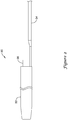
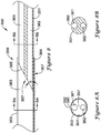
- the stent delivery system 10 which may be assembled prior to insertion into the body of a patient, either by the manufacturer or by the physician, includes a stent 20, a delivery catheter 30, and a push catheter 50.
- the push catheter 50 may extend over the delivery catheter 30 such that the distal end 52 of the push catheter 50 abuts the proximal end 22 of the stent 20.
- the stent 20 may be formed of any suitable material, such as a metallic material or a polymeric material.
- suitable metallic materials include, but are not necessarily limited to, stainless steel, tungsten, nickel-titanium alloys such as those possessing shape memory properties commonly referred to as nitinol, nickel-chromium alloys, nickel-chromium-iron alloys, or other suitable metals, or combinations or alloys thereof.
- suitable polymeric materials include, but are not necessarily limited to, polyamide, polyether block amide, polyethylene, polypropylene, polyvinylchloride, polyurethane, polytetrafluoroethylene, and copolymers, blends, mixtures or combinations thereof.
- the stent 20 may include a retention structure to prevent migration of the stent 20 within a body cavity.
- the stent 20 may include a first barb 26 and/or a second barb 28 which may assist in maintaining the stent 20 in a desired position within a body cavity.
- the barbs 26, 28 may be arranged in an opposing orientation such that the barbs 26, 28 may prevent the stent 20 from migrating in either axial direction.
- the stent 20 may include additional and/or alternative retention means which may prevent displacement of the stent 20 once positioned within a body cavity.
- the stent 20 may be selectively connected to the push catheter 50 using a retention device (not shown), such as a suture.
- a retention device such as a suture.
- U.S. Pat. No. 6,264,624 to Desmond, III et al. and U.S. Pat. No. 6,562,024 to Alvarez de Toledo et al. disclose the use of a suture as one such retention device.
- retention devices may be used to selectively removably connect the stent 20 to the push catheter 50.
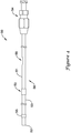
- the delivery catheter 30 is further described in FIGS. 2 and 3 .
- the delivery catheter 30 may include a body portion 32 and a pull wire 34.
- the body portion 32 may be a tubular member having a lumen 38 extending therethrough, and in some embodiments, the pull wire 34 may be a monofilament wire or a multi-filament wire, such as a braided wire.
- the body portion 32 and the pull wire 34 may each be formed of any suitable material, such as a polymeric material or a metallic material including, but not necessarily limited to, those materials listed elsewhere herein.
- the body portion 32 may be formed of a material dissimilar to that of the pull wire 34.
- the body portion 32 may be formed of a polymeric material while the pull wire 34 may be formed of a metallic material.
- a coupling 36 may be used to couple the body portion 32 to the pull wire 34.
- the coupling 36 may be a metallic member compatible with the metallic material of the pull wire 34.
- the pull wire 34 may be attached to the coupling 36 at the attachment location 35.
- the pull wire 34 may be attached to the coupling 36 by welding, brazing, soldering, or the like.
- the coupling 36 and the pull wire 34 may be a unitary member such that the coupling 36 may be integral with the pull wire 34.
- the coupling 36 may be a tubular member having a lumen 39 extending therethrough.
- the lumen 39 of the coupling 36 may be co-axial with the lumen 38 of the body portion 32, providing a passageway therethrough for the placement of another medical device, such as a guidewire.
- the coupling 36 may include one or more barbs 37, such as annular ridges, extending around the circumference of the coupling 36.
- the coupling 36 shown in FIG. 3 includes two barbs 37 positioned at two longitudinally spaced apart locations.
- the barbs 37 may extend around the entire circumference of the coupling 36, or the barbs 37 may extend only partially around the coupling 36 such as at radially spaced apart locations.
- the barbs 37 may be used to secure the body portion 32 of the delivery catheter 30 to the coupling 36, and thus the pull wire 34.
- the proximal portion of the body portion 32 may be inserted over the coupling 36 and urged proximally such that a portion of the body portion 32 extends over and past the barbs 37.
- the radial extents of the barbs 37 may be greater than the inside diameter of the body portion 32, such that the barbs 37 create an interference fit with the body portion 32.
- the orientation of the barbs 37 deters subsequent distal movement of the body portion 32 relative to the coupling 36, and thus inhibits detachment of the body portion 32 from the pull wire 34.
- a length of heat shrink tubing (not shown) may be placed about the body portion 32 overlaying the coupling 36 and then heat shrunk in place in order to further retain the body portion 32 to the coupling 36.
- the push catheter 50 is further described in FIG. 4 .
- the push catheter 50 may include a hub assembly 54 and an elongate shaft 56 extending distally therefrom.
- the elongate shaft 56 may include a radiopaque marker 55 proximate the distal end 52 of the elongate shaft 56, or at another location along the elongate shaft 56.
- the radiopaque marker 55 if present, may aid a physician in positioning the stent 20 (shown in FIG. 1 ) during a medical procedure.
- the elongate shaft 56 may include multiple sections such as a proximal section 51 and a distal section 53.
- the proximal section 51 may be a tubular member extrusion and the distal section 53 may be a tubular member extrusion distinct from the proximal section 51.
- the proximal section 51 may be attached to the distal section 53 at a joint 59 during a post-extrusion process.
- the proximal section 51 may be attached to the distal section 53 in any suitable fashion, such as fusion bonding (e.g., laser bonding), adhesive bonding, RF welding, compression fit, heat shrink connection, or the like.
- the proximal section 51 may be formed of a polymeric material different from the polymeric material of the distal section 53. In other embodiments, the proximal section 51 and the distal section 53 may be formed of a similar polymeric material. In some embodiments, the proximal section 51 may have a durometer hardness different from the durometer hardness of the distal section 53. For instance, the durometer hardness of the proximal section 51 may be greater than or less than the durometer hardness of the distal section 53.
- the durometer hardness of the proximal section 51 may be in the range of about 60D to about 90D, in the range of about 70D to about 80D, or in the range of about 70D to about 75D on the Shore hardness scale.
- the durometer hardness of the distal section 53 may be in the range of about 40D to about 80D, in the range of about 50D to about 70D, or in the range of about 60D to about 70D on the Shore hardness scale.
- the elongate shaft 56 may have three, four, or more sections or regions of differential stiffness.
- the elongate shaft 56 may have a first section with a first durometer hardness, a second section with a second durometer hardness greater than the first durometer hardness, and a third section with a third durometer hardness greater than both the first durometer hardness and the second durometer hardness.
- Other embodiments may include additional sections, such as a fourth section with a fourth durometer hardness greater than the first, second and third durometer hardness.
- the elongate shaft 56 of the push catheter 50 may be utilized in order to provide the elongate shaft 56 of the push catheter 50 with multiple sections or regions of differential stiffness. For example, one could switch from a first polymer to a second polymer having different stiffness properties during extrusion of one or more sections of the elongate shaft 56.
- the elongate shaft 56 may be formed of multiple layers of material along its length. Thus, fewer and/or thinner layers of material may be located throughout regions which are desired to be softer than adjacent regions of the elongate shaft 56, for example.
- one or more portions of the elongate shaft 56 may be reinforced with one or more reinforcement members, such as braids, coils, strips of coextruded material, heatshrink sleeves, elongate fibers, ribbing, etc.
- the sidewall of one or more select portions of the elongate shaft 56 may have a reduced thickness compared to an adjacent portion of the elongate shaft 56.
- the one or more regions of reduced thickness may be less stiff (e.g., have greater flexibility) than adjacent, thicker regions of the elongate shaft 56.
- Still other design choices may provide the elongate shaft 56 with multiple regions of differential flexibility or other desired characteristics.
- the elongate shaft 56 may include a side port 58 providing access to the interior of the elongate shaft 56.
- the side port 58 may provide a guidewire port for placement of a guidewire within a lumen of the elongate shaft 56.
- the side port 58 may be a skived portion of the elongate shaft 56, for example.
- the side port 58 is formed in the proximal section 51 of the elongate shaft 56. However, in other embodiments, the side port 58 may be formed in the distal section 53, if desired.
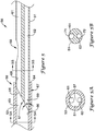
- FIG. 5 is an enlarged cross-sectional view of a portion of the elongate shaft 56 of the push catheter 50 (shown in FIG. 4 ) including the joint 59 between the distal section 53 and the proximal section 51 and the side port 58.
- the distal section 53 may be a single-lumen tubular member and the proximal section 51 may be a multi-lumen tubular member having two or more lumens.
- the distal section 53 includes a lumen 63 for receiving a portion of the proximal section 51.
- FIG. 5 is an enlarged cross-sectional view of a portion of the elongate shaft 56 of the push catheter 50 (shown in FIG. 4 ) including the joint 59 between the distal section 53 and the proximal section 51 and the side port 58.
- the distal section 53 may be a single-lumen tubular member and the proximal section 51 may be a multi-lumen tubular member having two or more lumens.
- the proximal section 51 may be a dual-lumen tubular member having a first lumen 61 and a second lumen 62. Each of the first lumen 61 and the second lumen 62 may be in association (e.g., in fluid communication) with the lumen 63 of the distal section 53.
- the side port 58 may provide access to the first lumen 61 of the proximal section 51.
- the proximal section 51 may be positioned within the lumen 63 of the distal section 53 such that the perimeter (e.g., circumference) of the first lumen 61 is tangent to the perimeter (e.g., circumference) of the lumen 63 of the distal section 53. Additionally or alternatively, the proximal section 51 may be positioned within the lumen 63 of the distal section 53 such that the perimeter (e.g., circumference) of the second lumen 62 is tangent to the perimeter (e.g., circumference) of the lumen 63 of the distal section 53.
- the term "tangent" is intended to mean a line, curve, or surface meeting another line, curve, or surface at a common point and/or sharing a common tangent line or tangent plane at that point.
- the curvature of the circumference of the inner surface of the lumen 63 meets the curvature of the circumference of the inner surface of the first lumen 61 and/or the curvature of the circumference of the inner surface of the second lumen 62, and the lumen 63 shares a common tangent line or tangent plane at that point with the first lumen 61 and/or the second lumen 62.
- Such an orientation may be found to facilitate advancing an elongate shaft, such as a guidewire, from the lumen 63 of the distal section 53 into the first lumen 61 and/or the second lumen 62 of the proximal section 51.
- the first lumen 61 which may be considered a guidewire lumen, may extend to the proximal end of the elongate shaft 56.
- the push catheter 50 may be optionally used as either an over-the-wire type catheter (where a guidewire is positioned within the first lumen 61 and extends throughout the length of the elongate shaft 56), or as a rapid-exchange type catheter (where the guidewire is positioned within the first lumen 61 through a distal portion of the push catheter 50, exits the push catheter 50 at the side port 58, and extends exterior to the push catheter 50 throughout a portion of the push catheter 50 proximal of the side port 58).
- the push catheter 50 may be operated as either a rapid-exchange catheter or as an over-the-wire catheter.
- the distal end 65 of the proximal section 51 may be formed at an oblique angle ⁇ to the longitudinal axis of the proximal section 51.
- the oblique angle ⁇ may be in the range of about 10 degrees to about 60 degrees, in the range of about 20 degrees to about 50 degrees, or in the range of about 30 degrees to about 45 degrees in some embodiments.
- the oblique angle ⁇ of the distal end 65 of the proximal section 51 forms a ramp 57 which may be used to facilitate directing a guidewire from the single lumen 63 of the distal section 53 to the first lumen 61 of the proximal section 51.
- the ramp 57 may also be viewed through the lumen 63 of the distal section 53 in the cross-section shown in FIG. 5A . Further discussion of the functionality of the ramp 57 will be described while discussing FIGS. 9A-9D .
- the side port 58 may be spaced apart from the joint 59 between the proximal section 51 and the distal section 53, and thus the ramp 57.
- the side port 58 may be located a distance proximal of the ramp 57.
- the side port 58 may be located about 2 to about 10 centimeters, about 4 to about 6 centimeters, or about 5 centimeters proximal of the ramp 57.
- suitable dimensions are disclosed, one of skill in the art, incited by the present disclosure, would understand that desired dimensions may deviate from those expressly disclosed. Placing the side port 58 at a location proximal of the ramp 57 may reduce the potential of kinking of the elongate shaft 56.
- the distal end 65 of the proximal section 51 is be positioned within the lumen 63 of the distal section 53 and the outer surface of a distal portion of the proximal section 51 secured to the distal section 53.
- the outer diameter of the proximal section 51 is be sized to fit within the lumen 63 of the distal section 53.
- the lumen 63 of the distal section 53 may have a stepped portion 67 proximate the proximal end 64 of the distal section 53 for receiving the distal portion of the proximal section 51.
- the internal stepped portion 67 may be bored out, or otherwise have an increased inner diameter relative to a more distal portion of the distal section 53.
- the outer diameter of the proximal section 51 may be similar to the inner diameter of the internal stepped portion 67, and thus may be greater than the inner diameter of a more distal portion of the distal section 53.
- the radial distance between the inner wall 66 of the lumen 63 of the distal section 53 and the inner wall 68 of the first lumen 61 of the proximal section 51 and/or the inner wall 69 of the second lumen 62 of the proximal section 51 may be reduced and/or eliminated.
- the edge of the distal end 65 of the proximal section 51 which could impede the proximal advancement of a guidewire through the lumen 63 into the first lumen 61 of the proximal section 51, may be reduced or eliminated.
- the outer wall 71 of the first lumen 61 may be thinner than the outer wall 72 of the second lumen 62.
- the outer wall 71 of the first lumen 61 may be about 0.075 millimeters to about 0.125 millimeters (0.003 inches to about 0.005 inches) in thickness.
- suitable dimensions are disclosed, one of skill in the art, incited by the present disclosure, would understand that desired dimensions may deviate from those expressly disclosed.
- the offset first lumen 61 and/or the relatively thin outer wall 71 may facilitate advancing a guidewire through the first lumen 61 and/or through the side port 58.
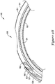
- FIG. 6 An alternative embodiment of a portion of an elongate shaft 156 including a joint 159 between a distal section 153 and a proximal section 151 and a side port 158 is shown in FIG. 6 .
- the portion of the elongate shaft 156 may be similar to the portion of the elongate shaft 56 of the push catheter 50 as shown in FIG. 5 .
- the proximal section 151 may have different flexibility characteristics from the distal section 153.
- similarities of the portion of the elongate shaft 156 shown in FIG. 6 with those of the portion of the elongate shaft 56 shown in FIG. 5 will not be repeated.
- a ramp 170 is illustratively positioned within the first lumen 161 proximate the side port 158.
- the ramp 170 may be placed within the first lumen 161 in order to direct a guidewire extending through the first lumen 161 exterior of the elongate shaft 156 through the side port 158.
- the ramp 170 may be a separate member positioned and secured within the first lumen 161, or the ramp 170 may be integrally formed in the proximal section 151 of the elongate shaft 156, such as during formation of the side port 158.
- the proximal section 151 may be attached to the distal section 153, such as at joint 159, such that each of the first lumen 161 and the second lumen 162 of the proximal section 151 are in association (e.g., in fluid communication) with the lumen 163 of the distal section 153. Additionally, the distal end 165 of the proximal section 151 may be formed at an oblique angle ⁇ to the longitudinal axis of the proximal section 151. For instance, the oblique angle ⁇ may be in the range of about 10 degrees to about 60 degrees, in the range of about 20 degrees to about 50 degrees, or in the range of about 30 degrees to about 45 degrees in some embodiments. Although some suitable values are disclosed, one of skill in the art, incited by the present disclosure, would understand that desired values may deviate from those expressly disclosed.
- the oblique angle ⁇ of the distal end 165 of the proximal section 151 forms a ramp 157 which may be used to facilitate directing a guidewire from the single lumen 163 of the distal section 153 to the first lumen 161 of the proximal section 151.
- the ramp 157 may also be viewed through the lumen 163 of the distal section 153 in the cross-section shown in FIG. 6A .
- the distal end 165 of the proximal section 151 is shown in abutment with and secured to the proximal end 164 of the distal section 153.
- the outer diameter of the proximal section 151 may be substantially equivalent to the outer diameter of the distal section 153.
- a connector 175, such as a length of heat shrink tubing may be placed over the joint 159 between the proximal section 151 and the distal section 153 in order to further secure the proximal section 151 with the distal section 153.
- the side port 158 may be spaced apart from the joint 159 between the proximal section 151 and the distal section 153, and thus the ramp 157.
- the side port 158 may be located a distance proximal of the ramp 157.
- the side port 158 may be located about 2 to about 10 centimeters, about 4 to about 6 centimeters, or about 5 centimeters proximal of the ramp 157.
- suitable dimensions are disclosed, one of skill in the art, incited by the present disclosure, would understand that desired dimensions may deviate from those expressly disclosed. Placing the side port 158 at a location proximal of the ramp 157 may reduce the potential of kinking of the elongate shaft 156.
- the ramp 157 may be positioned across a portion of the lumen 163 of the distal section 153.
- the proximal section 151 may be positioned within the lumen 163 of the distal section 153 such that the perimeter (e.g., circumference) of the first lumen 161 is tangent to the perimeter (e.g., circumference) of the lumen 163 of the distal section 153.
- the proximal section 151 may be positioned within the lumen 163 of the distal section 153 such that the perimeter (e.g., circumference) of the second lumen 162 is tangent to the perimeter (e.g., circumference) of the lumen 163 of the distal section 153.
- the term "tangent" is intended to mean a line, curve, or surface meeting another line, curve, or surface at a common point and/or sharing a common tangent line or tangent plane at that point.
- the curvature of the circumference of the inner surface of the lumen 163 meets the curvature of the circumference of the inner surface of the first lumen 161 and/or the curvature of the circumference of the inner surface of the second lumen 162, and the lumen 163 shares a common tangent line or tangent plane at that point with the first lumen 161 and/or the second lumen 162.
- Such an orientation may be found to facilitate advancing an elongate shaft, such as a guidewire, from the lumen 163 of the distal section 153 into the first lumen 161 and/or the second lumen 162 of the proximal section 151.
- the first lumen 161, as well as the second lumen 162 may be offset from the longitudinal axis of the proximal section 151.
- the offset first lumen 161 may facilitate advancing a guidewire through the first lumen 161 and/or through the side port 158.
- the ramp 170 is shown occluding the first lumen 161 of the proximal section 151.
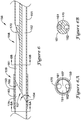
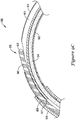
- FIG. 7 Another alternative embodiment of a portion of an elongate shaft 256 including a joint 259 between a distal section 253 and a proximal section 251 is shown in FIG. 7 .
- the portion of the elongate shaft 256 may be similar to the portion of the elongate shaft 56 of the push catheter 50 as shown in FIG. 5 .
- the proximal section 251 may have different flexibility characteristics from the distal section 253.
- similarities of the portion of the elongate shaft 256 shown in FIG. 7 with those of the portion of the elongate shaft 56 shown in FIG. 5 will not be repeated.
- the proximal section 251 of the elongate shaft 256 shown in FIG. 7 may include a "U” or “C” channel 261 forming a lumen for receiving a guidewire therethrough and a second lumen 262.
- a longitudinal slot 280 extending along the length, or a portion thereof, of the proximal section 251 may allow access through the sidewall of the proximal section 251 to the "U" or "C” channel 261 of the proximal section 251.
- the distal section 253 may be a tubular member having a lumen 263 extending therethrough.
- Each of the "U” or “C” channel 261 and the lumen 262 of the proximal section 251 may be in association (e.g., in fluid communication) with the lumen 263 of the distal section 253.
- the "U” or “C” channel 261 allows a guidewire to be selectively retained within the “U” or “C” channel 261, or the guidewire may be removed from the "U” or “C” channel 261, as desired during a medical procedure.
- a push catheter including a "U” or “C” channel 261 may be selectively used in an over-the-wire manner and/or in a rapid-exchange manner.
- the distal end 265 of the proximal section 251 may be formed at an oblique angle ⁇ to the longitudinal axis of the proximal section 251.
- the oblique angle ⁇ may be in the range of about 10 degrees to about 60 degrees, in the range of about 20 degrees to about 50 degrees, or in the range of about 30 degrees to about 45 degrees in some embodiments.
- the oblique angle ⁇ of the distal end 265 of the proximal section 251 forms a ramp 257 which may be used to facilitate directing a guidewire from the single lumen 263 of the distal section 253 to the "C" or "U” channel 261 of the proximal section 251.
- the ramp 257 may also be viewed through the lumen 263 of the distal section 253 in the cross-section shown in FIG. 7A .
- the distal end 265 of the proximal section 251 may be positioned within the lumen 263 of the distal section 253 and the outer surface of a distal portion of the proximal section 251 secured to the distal section 253.
- the outer diameter of the proximal section 251 may be sized to fit within the lumen 263 of the distal section 253.
- the lumen 263 of the distal section 253 may have a stepped portion 267 proximate the proximal end 264 of the distal section 253 for receiving the distal portion of the proximal section 251.
- the internal stepped portion 267 may be bored out, or otherwise have an increased inner diameter relative to a more distal portion of the distal section 253.
- the outer diameter of the proximal section 251 may be similar to the inner diameter of the internal stepped portion 267, and thus may be greater than the inner diameter of a more distal portion of the distal section 253.
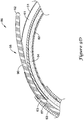
- FIG. 8 Another alternative embodiment of a portion of an elongate shaft 356 including a joint 359 between a distal section 353 and a proximal section 351 is shown in FIG. 8 .
- the portion of the elongate shaft 356 may be similar to the portion of the elongate shaft 56 of the push catheter 50 as shown in FIG. 5 .
- the proximal section 351 may have different flexibility characteristics from the distal section 353.
- similarities of the portion of the elongate shaft 356 shown in FIG. 8 with those of the portion of the elongate shaft 56 shown in FIG. 5 will not be repeated.
- the distal section 353 of the elongate shaft 356 shown in FIG. 8 may include a tubular member including a longitudinal slot 382 extending along the length, or a portion thereof, of the distal section 353 which may allow access through the sidewall of the distal section 353 to the lumen 363 of the distal section 353.
- the proximal section 351 of the elongate shaft 356 shown in FIG. 8 may include a "U” or “C” channel 361 forming a lumen for receiving a guidewire therethrough and a second lumen 362.
- a longitudinal slot 380 extending along the length, or a portion thereof, of the proximal section 351 may allow access through the sidewall of the proximal section 351 to the "U" or "C” channel 361 of the proximal section 351.
- the longitudinal slot 380 may be aligned with the longitudinal slot 382.
- Each of the "U” or “C” channel 361 and the lumen 362 may be in association (e.g., in fluid communication) with the lumen 363 of the distal section 353.
- the longitudinal slot 382 of the distal section 353 allows a guidewire to be selectively removed from the confines of the lumen 363 of the distal section 353 and/or inserted into the lumen 363 of the distal section 353 as desired.
- the "U" or “C” channel 361 of the proximal section 351 allows a guidewire to be selectively retained within the "U” or “C” channel 361, or the guidewire may be removed from the "U” or “C” channel 361 and/or the lumen 363 of the distal section 353, as desired during a medical procedure.
- a push catheter including a longitudinal slot 380/382 and/or a "U” or “C” channel 361 may be selectively used in an over-the-wire manner and/or in a rapid-exchange manner.
- the distal end 365 of the proximal section 351 may be formed at an oblique angle ⁇ to the longitudinal axis of the proximal section 351.
- the oblique angle ⁇ may be in the range of about 10 degrees to about 60 degrees, in the range of about 20 degrees to about 50 degrees, or in the range of about 30 degrees to about 45 degrees in some embodiments.
- the oblique angle ⁇ of the distal end 365 of the proximal section 351 forms a ramp 357 which may be used to facilitate directing a guidewire from the lumen 363 of the distal section 353 to the "C" or "U” channel 361 of the proximal section 351.
- the ramp 357 may also be viewed through the lumen 363 of the distal section 353 in the cross-section shown in FIG. 8A .
- the distal end 365 of the proximal section 351 may be positioned within the lumen 363 of the distal section 353 and the outer surface of a distal portion of the proximal section 351 secured to the distal section 353.
- the outer diameter of the proximal section 351 may be sized to fit within the lumen 363 of the distal section 353.
- the lumen 363 of the distal section 353 may have an inner diameter proximate the proximal end 364 of the distal section 353 sized for receiving the distal portion of the proximal section 351.
- the outer diameter of the distal portion of the proximal section 351 proximate the distal end 365 of the proximal section 351 may be substantially equal to the inner diameter of the distal section 353 proximate the proximal end 364 of the distal section 353.
- FIGS. 9A-9D are a sequence of figures illustrating the advancement of a guidewire 90 through the elongate shaft 56 of the push catheter 50 while retaining the elongate shaft 56 in a curved orientation with the side port 58 positioned at the outer radius of the curved portion of the elongate shaft 56.
- the pull wire 34 is positioned within the second lumen 62 of the proximal section 51 and the lumen 63 of the distal section 53. The pull wire 34 is positioned, as a result of the curved orientation of the elongate shaft 56, along the inner radius of the curved portion of the elongate shaft 56.
- the guidewire 90 is approaching the ramp 57 formed by the oblique angle ⁇ of the distal end 65 of the proximal section 51, yet fully within the distal section 53.
- the position of the pull wire 34 partially occludes the lumen 63 of the distal section 53, such that the guidewire 90 is located in the radially outward portion of the curve of the lumen 63.
- the guidewire 90 is precluded from entering the second lumen 62.
- the leading edge 92 of the guidewire 90 contacts the inner surface of the lumen 63 along the outer radius of the curve.
- the ramp 57 facilitates advancing the guidewire 90 into the first lumen 61 of the proximal section 51.
- the leading edge 92 of the guidewire 90 further maintains contact with the inner surface of the first lumen 61 along the outer radius of the curve.
- the inner surface of the first lumen 61 along the outer radius of the curve alters the natural tendency of the guidewire 90 and urges the guidewire 90 to follow the curvature of the first lumen 61.
- the leading edge 92 of the guidewire 90 encounters the side port 58, also located along the outer radius of the curve of the elongate shaft 56.
- the guidewire 90 exits the lumen 61 through the side port 58, as shown in FIG. 9C . This is due to the fact that through the region of the side port 58, the inner wall of the first lumen 61 no longer impedes the guidewire 90 from advancing in a straight path.
- the guidewire 90 may be further advanced proximally exterior of the elongate shaft 56, as shown in FIG. 9D .
- the push catheter 50 and guidewire 90 are arranged such that the push catheter 50 may be used as a rapid-exchange catheter.
- a solid mono-filament wire used as the pull wire 34 may provide guidewire-like stiffness to the proximal portion of the elongate shaft 56 where the guidewire 90 is positioned external of the elongate shaft 56.
- the pull wire 34 may provide attributes associated with an over-the-wire catheter configuration (wherein the guidewire would provide stiffness and pushability to the proximal portion), yet retain the benefits of a rapid-exchange catheter configuration.
- the portion of the elongate shaft 56 including the side port 58 may be retained in a straight configuration during advancement of the guidewire 90 through the elongate shaft 56.
- the guidewire instead of exiting the elongate shaft 56 through the side port 58, the guidewire passes the side port 58 of the proximal section 51 and advances through the first lumen 61 proximally of the side port 58. This is due to the fact that as the natural tendency of the guidewire 90 is to advance in a straight path, the guidewire 90 will remain in the straight path created by the first lumen 61.
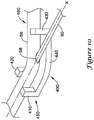
- a tool 400 which may be used to urge the elongate shaft 56 of the push catheter 50 into a curved orientation is shown in FIG. 10 .
- the tool 400 includes a body portion 440, a securement portion 450 including a first leg 410 and a second leg 420, and biasing portion 460 including a third leg 430.
- Each of the first, second and third legs 410, 420, 430 extend from the body portion 440.
- the first leg 410 and the second leg 420 are arranged such that the first and second legs 410, 420 bound the elongate shaft 56 on opposing sides.
- the first leg 410 and the second leg 420 may be opposite or slightly offset from one another.
- the first and second legs 410, 420 may include a curved portion such as a concave surface, a protrusion, or otherwise may include structure for retaining the elongate shaft 56 between the first and second legs 410, 420.
- the first and second legs 410, 420 may provide an interference or interlocking fit with the elongate shaft 56.
- the third leg 430 may be placed a distance from the first and second legs 410, 420.
- the third leg 430 may be misaligned from the first and second legs 410, 420 such that placement of the elongate shaft 56 adjacent to the third leg 430 biases the elongate shaft 56, imparting a curvature in the elongate shaft 56.
- the third leg 430 may additionally or alternatively include a curved portion such as a concave surface, a protrusion, or otherwise may include structure for retaining the elongate shaft 56.
- the elongate shaft 56 may be positioned such that the side port 58 is positioned between the securement portion 450 (i.e., the first and second legs 410, 420) and the biasing portion 460 (i.e., the third leg 430) of the tool 400.
- the side port 58 may be positioned along the outer radius of the curvature of the elongate shaft 56 formed between the first and second legs 410, 420 and the third leg 430 in an orientation similar to that illustrated in FIGS. 9A-9D .
- the tool 400 which provides a curvature to the elongate shaft 56, may facilitate the guidewire 90 exiting the elongate shaft 56 through the side port 58 such as illustrated in FIGS. 9A-9D .
Landscapes
- Health & Medical Sciences (AREA)
- Engineering & Computer Science (AREA)
- Biomedical Technology (AREA)
- Cardiology (AREA)
- Oral & Maxillofacial Surgery (AREA)
- Transplantation (AREA)
- Heart & Thoracic Surgery (AREA)
- Vascular Medicine (AREA)
- Life Sciences & Earth Sciences (AREA)
- Animal Behavior & Ethology (AREA)
- General Health & Medical Sciences (AREA)
- Public Health (AREA)
- Veterinary Medicine (AREA)
- Media Introduction/Drainage Providing Device (AREA)
Applications Claiming Priority (2)
| Application Number | Priority Date | Filing Date | Title |
|---|---|---|---|
| US11/620,437 US20080167628A1 (en) | 2007-01-05 | 2007-01-05 | Stent delivery system |
| PCT/US2007/088695 WO2008085714A2 (en) | 2007-01-05 | 2007-12-21 | Stent delivery system |
Publications (2)
| Publication Number | Publication Date |
|---|---|
| EP2120803A2 EP2120803A2 (en) | 2009-11-25 |
| EP2120803B1 true EP2120803B1 (en) | 2018-06-06 |
Family
ID=39313349
Family Applications (1)
| Application Number | Title | Priority Date | Filing Date |
|---|---|---|---|
| EP07869825.5A Active EP2120803B1 (en) | 2007-01-05 | 2007-12-21 | Stent delivery system |
Country Status (5)
| Country | Link |
|---|---|
| US (1) | US20080167628A1 (ja) |
| EP (1) | EP2120803B1 (ja) |
| JP (1) | JP2010515486A (ja) |
| CA (1) | CA2673937A1 (ja) |
| WO (1) | WO2008085714A2 (ja) |
Families Citing this family (20)
| Publication number | Priority date | Publication date | Assignee | Title |
|---|---|---|---|---|
| US7780730B2 (en) | 2006-09-25 | 2010-08-24 | Iyad Saidi | Nasal implant introduced through a non-surgical injection technique |
| MX2011003746A (es) * | 2008-10-10 | 2011-11-04 | Nexeon Medsystems Inc | Sistema de cateter frugal de inventario. |
| US9597220B2 (en) | 2008-11-19 | 2017-03-21 | Spirox, Inc. | Apparatus and methods for correcting nasal valve collapse |
| EP2376171B1 (en) * | 2008-12-10 | 2018-04-25 | Microvention, Inc. | Microcatheter |
| EP2400426B1 (en) | 2009-01-30 | 2013-03-13 | Research In Motion Limited | System and method for access control in a portable electronic device |
| US8771335B2 (en) * | 2009-09-21 | 2014-07-08 | Boston Scientific Scimed, Inc. | Rapid exchange stent delivery system |
| BR112013021755B1 (pt) | 2011-02-25 | 2021-08-31 | Microvention, Inc | Cateter de balão |
| WO2013003450A1 (en) | 2011-06-27 | 2013-01-03 | Boston Scientific Scimed, Inc. | Stent delivery systems and methods for making and using stent delivery systems |
| EP2776108B1 (en) | 2011-11-09 | 2019-07-17 | Boston Scientific Scimed, Inc. | Guide extension catheter |
| EP2809384B1 (en) * | 2012-01-31 | 2017-09-27 | Boston Scientific Scimed, Inc. | Guide extension catheter |
| TW201334822A (zh) * | 2012-02-28 | 2013-09-01 | Sumitomo Bakelite Co | 醫療機器之製造方法及醫療機器 |
| CA3161309A1 (en) * | 2013-02-27 | 2014-09-04 | Spirox, Inc. | Nasal implants and systems and methods of use |
| JP5748135B2 (ja) * | 2013-05-10 | 2015-07-15 | オリンパス株式会社 | ステントデリバリーシステム |
| EP3185819A4 (en) | 2014-08-26 | 2018-03-14 | Spirox, Inc. | Nasal implants and systems and method of use |
| US10098768B2 (en) | 2014-09-15 | 2018-10-16 | Cook Medical Technologies Llc | Ratchet operated vascular intervention device delivery system |
| CN106456939A (zh) * | 2015-03-25 | 2017-02-22 | 奥林巴斯株式会社 | 处置器具 |
| CN113349985A (zh) | 2015-09-25 | 2021-09-07 | 斯贝洛克斯公司 | 鼻植入物和系统及使用方法 |
| EP3451894B1 (en) | 2016-05-02 | 2023-11-15 | Entellus Medical, Inc. | Nasal valve implants |
| WO2018075700A1 (en) | 2016-10-18 | 2018-04-26 | Boston Scientific Scimed, Inc. | Guide extension catheter |
| GB201820151D0 (en) * | 2018-12-11 | 2019-01-23 | Cook Medical Technologies Llc | Introducer assembly particularly for balloon catheters |
Family Cites Families (105)
| Publication number | Priority date | Publication date | Assignee | Title |
|---|---|---|---|---|
| US2836215A (en) * | 1954-08-11 | 1958-05-27 | Illinois Tool Works | Plastic nut-like fastener with resilient wings |
| AU5722173A (en) * | 1972-07-04 | 1975-01-09 | Stanley Francis Duturbure | Catheter tube |
| US3890977A (en) * | 1974-03-01 | 1975-06-24 | Bruce C Wilson | Kinetic memory electrodes, catheters and cannulae |
| US4194513A (en) * | 1977-05-05 | 1980-03-25 | Indiana University Foundation | Antenatal cell extracting device and method |
| USRE31855F1 (en) * | 1978-12-01 | 1986-08-19 | Tear apart cannula | |
| US4425919A (en) * | 1981-07-27 | 1984-01-17 | Raychem Corporation | Torque transmitting catheter apparatus |
| US4423725A (en) * | 1982-03-31 | 1984-01-03 | Baran Ostap E | Multiple surgical cuff |
| US4445892A (en) * | 1982-05-06 | 1984-05-01 | Laserscope, Inc. | Dual balloon catheter device |
| US4581017B1 (en) * | 1983-03-07 | 1994-05-17 | Bard Inc C R | Catheter systems |
| US4582181A (en) * | 1983-08-12 | 1986-04-15 | Advanced Cardiovascular Systems, Inc. | Steerable dilatation catheter |
| FR2563726B1 (fr) * | 1984-05-04 | 1986-10-10 | Robert Cassou | Appareil d'insemination artificielle, notamment des carnivores |
| US4573470A (en) * | 1984-05-30 | 1986-03-04 | Advanced Cardiovascular Systems, Inc. | Low-profile steerable intraoperative balloon dilitation catheter |
| US4917088A (en) * | 1985-05-02 | 1990-04-17 | C. R. Bard, Inc. | Balloon dilation probe |
| US4641654A (en) * | 1985-07-30 | 1987-02-10 | Advanced Cardiovascular Systems, Inc. | Steerable balloon dilatation catheter assembly having dye injection and pressure measurement capabilities |
| US4917103A (en) * | 1985-09-18 | 1990-04-17 | C. R. Bard, Inc. | Guide wire extension |
| US4655746A (en) * | 1985-12-02 | 1987-04-07 | Target Therapeutics | Catheter device |
| US4646742A (en) * | 1986-01-27 | 1987-03-03 | Angiomedics Incorporated | Angioplasty catheter assembly |
| US5350395A (en) * | 1986-04-15 | 1994-09-27 | Yock Paul G | Angioplasty apparatus facilitating rapid exchanges |
| US4723550A (en) * | 1986-11-10 | 1988-02-09 | Cordis Corporation | Leakproof hemostasis valve with single valve member |
| US4997421A (en) * | 1986-12-10 | 1991-03-05 | Dale Medical Products, Inc. | IV connector lock and stabilizer |
| US4748982A (en) * | 1987-01-06 | 1988-06-07 | Advanced Cardiovascular Systems, Inc. | Reinforced balloon dilatation catheter with slitted exchange sleeve and method |
| US5002532A (en) * | 1987-01-06 | 1991-03-26 | Advanced Cardiovascular Systems, Inc. | Tandem balloon dilatation catheter |
| US4988356A (en) * | 1987-02-27 | 1991-01-29 | C. R. Bard, Inc. | Catheter and guidewire exchange system |
| DE3715699A1 (de) * | 1987-05-12 | 1988-12-01 | Foerster Ernst | Katheter und endoskop zur transpapillaeren darstellung der gallenblase |
| US4798193A (en) * | 1987-05-18 | 1989-01-17 | Thomas J. Fogarty | Protective sheath instrument carrier |
| US4817613A (en) * | 1987-07-13 | 1989-04-04 | Devices For Vascular Intervention, Inc. | Guiding catheter |
| US4813934A (en) * | 1987-08-07 | 1989-03-21 | Target Therapeutics | Valved catheter device and method |
| US4798594A (en) * | 1987-09-21 | 1989-01-17 | Cordis Corporation | Medical instrument valve |
| US4819751A (en) * | 1987-10-16 | 1989-04-11 | Baxter Travenol Laboratories, Inc. | Valvuloplasty catheter and method |
| US4906241A (en) * | 1987-11-30 | 1990-03-06 | Boston Scientific Corporation | Dilation balloon |
| US4892519A (en) * | 1987-12-03 | 1990-01-09 | Advanced Cardiovascular Systems, Inc. | Steerable perfusion dilatation catheter |
| US4917667A (en) * | 1988-02-11 | 1990-04-17 | Retroperfusion Systems, Inc. | Retroperfusion balloon catheter and method |
| US5425711A (en) * | 1988-02-29 | 1995-06-20 | Scimed Life Systems, Inc. | Intravascular catheter with distal guide wire lumen and transition member |
| US4838268A (en) * | 1988-03-07 | 1989-06-13 | Scimed Life Systems, Inc. | Non-over-the wire balloon catheter |
| US4835824A (en) * | 1988-04-13 | 1989-06-06 | Durham Vaughn L | Medical clamp |
| US4998917A (en) * | 1988-05-26 | 1991-03-12 | Advanced Cardiovascular Systems, Inc. | High torque steerable dilatation catheter |
| US4994027A (en) * | 1988-06-08 | 1991-02-19 | Farrell Edward M | Percutaneous femoral bypass system |
| US4986814A (en) * | 1988-06-13 | 1991-01-22 | Indianapolis Center For Advanced Research | One-punch catheter |
| DE3825631A1 (de) * | 1988-07-28 | 1990-02-08 | Osypka Peter | Vorrichtung zum transvenoesen oder arteriellen einfuehren mittels eines fuehrungsdrahtes |
| US4998923A (en) * | 1988-08-11 | 1991-03-12 | Advanced Cardiovascular Systems, Inc. | Steerable dilatation catheter |
| US4898577A (en) * | 1988-09-28 | 1990-02-06 | Advanced Cardiovascular Systems, Inc. | Guiding cathether with controllable distal tip |
| US4917666A (en) * | 1988-11-14 | 1990-04-17 | Medtronic Versaflex, Inc. | Steerable thru-lumen catheter |
| US5090958A (en) * | 1988-11-23 | 1992-02-25 | Harvinder Sahota | Balloon catheters |
| US4932959A (en) * | 1988-12-01 | 1990-06-12 | Advanced Cardiovascular Systems, Inc. | Vascular catheter with releasably secured guidewire |
| US4983168A (en) * | 1989-01-05 | 1991-01-08 | Catheter Technology Corporation | Medical layered peel away sheath and methods |
| US4927418A (en) * | 1989-01-09 | 1990-05-22 | Advanced Cardiovascular Systems, Inc. | Catheter for uniform distribution of therapeutic fluids |
| US5085636A (en) * | 1989-01-13 | 1992-02-04 | Scimed Life Systems, Inc. | Balloon catheter with inflation-deflation valve |
| US5221260A (en) * | 1989-01-13 | 1993-06-22 | Scimed Life Systems, Inc. | Innerless dilatation balloon catheter |
| US4900184A (en) * | 1989-02-10 | 1990-02-13 | Cleveland William G | Stirrup clip |
| US4928693A (en) * | 1989-03-13 | 1990-05-29 | Schneider (Usa), Inc. | Pressure monitor catheter |
| US4932413A (en) * | 1989-03-13 | 1990-06-12 | Schneider (Usa), Inc. | Guidewire exchange catheter |
| US5015231A (en) * | 1989-04-21 | 1991-05-14 | Scimed Life Systems, Inc. | Multipart split sleeve balloon protector for dilatation catheter |
| US5120308A (en) * | 1989-05-03 | 1992-06-09 | Progressive Angioplasty Systems, Inc. | Catheter with high tactile guide wire |
| US5026607A (en) * | 1989-06-23 | 1991-06-25 | C. R. Bard, Inc. | Medical apparatus having protective, lubricious coating |
| US5180367A (en) * | 1989-09-06 | 1993-01-19 | Datascope Corporation | Procedure and balloon catheter system for relieving arterial or veinal restrictions without exchanging balloon catheters |
| US5114403A (en) * | 1989-09-15 | 1992-05-19 | Eclipse Surgical Technologies, Inc. | Catheter torque mechanism |
| US5078681A (en) * | 1989-10-23 | 1992-01-07 | Olympus Optical Co., Ltd. | Balloon catheter apparatus with releasable distal seal and method of operation |
| US5209728B1 (en) * | 1989-11-02 | 1998-04-14 | Danforth Biomedical Inc | Low profile high performance interventional catheters |
| US5007901A (en) * | 1989-11-24 | 1991-04-16 | Shields Jack W | Intravenous catheter insertion device |
| US5125915A (en) * | 1990-03-02 | 1992-06-30 | Cardiopulmonics, Inc. | Locking y-connector for selective attachment to exterior of medical tubing |
| US5176637A (en) * | 1990-04-19 | 1993-01-05 | Terumo Kabushiki Kaisha | Catheter equipped with a dilation element |
| JP2514087Y2 (ja) * | 1990-05-25 | 1996-10-16 | 幸三 牧田 | 離脱式両端逆止弁付きバル―ン |
| EP0476807A1 (en) * | 1990-09-17 | 1992-03-25 | C.R. Bard, Inc. | Core wire steerable catheters |
| CA2068483A1 (en) * | 1991-05-15 | 1992-11-16 | Motasim Mahmoud Sirhan | Low profile dilatation catheter |
| US5290247A (en) * | 1991-05-21 | 1994-03-01 | C. R. Bard, Inc. | Intracoronary exchange apparatus and method |
| US5395335A (en) * | 1991-05-24 | 1995-03-07 | Jang; G. David | Universal mode vascular catheter system |
| EP0592720B1 (en) * | 1991-06-10 | 1998-07-29 | Cordis Corporation | Replaceable dilatation catheter |
| US5205822A (en) * | 1991-06-10 | 1993-04-27 | Cordis Corporation | Replaceable dilatation catheter |
| US5125905A (en) * | 1991-06-27 | 1992-06-30 | Boc Health Care, Inc. | Guidewire straightener |
| US5490837A (en) * | 1991-07-05 | 1996-02-13 | Scimed Life Systems, Inc. | Single operator exchange catheter having a distal catheter shaft section |
| EP0600940B1 (en) * | 1991-07-24 | 1999-02-24 | Advanced Cardiovascular Systems, Inc. | Low profile perfusion-type dilatation catheter |
| US5324269A (en) * | 1991-09-19 | 1994-06-28 | Baxter International Inc. | Fully exchangeable dual lumen over-the-wire dilatation catheter with rip seam |
| US5389087A (en) * | 1991-09-19 | 1995-02-14 | Baxter International Inc. | Fully exchangeable over-the-wire catheter with rip seam and gated side port |
| US5217434A (en) * | 1991-10-15 | 1993-06-08 | Scimed Life Systems, Inc. | Innerless dilatation catheter with balloon stretch valve |
| ATE118363T1 (de) * | 1991-12-11 | 1995-03-15 | Schneider Europ Ag | Ballonkatheter. |
| US5195978A (en) * | 1991-12-11 | 1993-03-23 | Baxter International Inc. | Rapid exchange over-the-wire catheter with breakaway feature |
| US5324259A (en) * | 1991-12-18 | 1994-06-28 | Advanced Cardiovascular Systems, Inc. | Intravascular catheter with means to seal guidewire port |
| US5599300A (en) * | 1992-05-11 | 1997-02-04 | Arrow Precision Products, Inc. | Method for electrosurgically obtaining access to the biliary tree with an adjustably positionable needle-knife |
| JPH06511409A (ja) * | 1992-05-11 | 1994-12-22 | メディカル イノベイションズ コーポレイション | 改良形胆管カテーテル |
| US5282479A (en) * | 1992-10-13 | 1994-02-01 | Boc Health Care, Inc. | Guidewire introducer with guidewire grasp and release means |
| US5290241A (en) * | 1992-10-16 | 1994-03-01 | Danforth Biomedical, Incorporated | Rapid removal over-the-wire catheter |
| US5314408A (en) * | 1992-11-13 | 1994-05-24 | Cardiovascular Imaging Systems, Inc. | Expandable member for a catheter system |
| US5304198A (en) * | 1992-11-13 | 1994-04-19 | Target Therapeutics | Single-lumen balloon catheter having a directional valve |
| US5382234A (en) * | 1993-04-08 | 1995-01-17 | Scimed Life Systems, Inc. | Over-the-wire balloon catheter |
| US5308318A (en) * | 1993-05-07 | 1994-05-03 | Plassche Jr Walter M | Easy-exchange drainage catheter system with integral obturator channel |
| US5320602A (en) * | 1993-05-14 | 1994-06-14 | Wilson-Cook Medical, Inc. | Peel-away endoscopic retrograde cholangio pancreatography catheter and a method for using the same |
| US5489271A (en) * | 1994-03-29 | 1996-02-06 | Boston Scientific Corporation | Convertible catheter |
| US5480389A (en) * | 1994-08-09 | 1996-01-02 | Becton, Dickinson And Company | Method and apparatus for adjusting the length of a combined spinal-epidural needle |
| US5706827A (en) * | 1994-09-21 | 1998-01-13 | Scimed Life Systems, Inc. | Magnetic lumen catheter |
| GB9601147D0 (en) * | 1996-01-19 | 1996-03-20 | Smiths Industries Ltd | Spinal epidural needle assemblies |
| US6346093B1 (en) * | 1996-09-13 | 2002-02-12 | Scimed Life Systems, Inc. | Single operator exchange biliary catheter with common distal lumen |
| US6582401B1 (en) * | 1996-09-13 | 2003-06-24 | Scimed Life Sytems, Inc. | Multi-size convertible catheter |
| US6117128A (en) * | 1997-04-30 | 2000-09-12 | Kenton W. Gregory | Energy delivery catheter and method for the use thereof |
| US6248100B1 (en) * | 1997-08-14 | 2001-06-19 | Scimed Life Systems, Inc. | Drainage catheter delivery system |
| US6159195A (en) * | 1998-02-19 | 2000-12-12 | Percusurge, Inc. | Exchange catheter and method of use |
| US6394141B2 (en) * | 1998-08-10 | 2002-05-28 | Specialty Silicone Fabricators, Inc. | Single lumen to multiple lumen transition catheter and method |
| US6387324B1 (en) * | 1999-09-30 | 2002-05-14 | Therox, Inc. | Apparatus and method for blood oxygenation |
| US6592549B2 (en) * | 2001-03-14 | 2003-07-15 | Scimed Life Systems, Inc. | Rapid exchange stent delivery system and associated components |
| CA2449961A1 (en) * | 2001-06-27 | 2003-01-09 | Salviac Limited | A catheter |
| CA2449981A1 (en) * | 2001-06-27 | 2003-01-09 | Salviac Limited | A catheter |
| EP1399084A1 (en) * | 2001-06-27 | 2004-03-24 | Salviac Limited | A catheter |
| IE20020535A1 (en) * | 2001-06-27 | 2003-05-28 | Salviac Ltd | A Catheter |
| CA2513082C (en) * | 2003-01-15 | 2010-11-02 | Angiomed Gmbh & Co. Medizintechnik Kg | Trans-luminal surgical device |
| GB0327306D0 (en) * | 2003-11-24 | 2003-12-24 | Angiomed Gmbh & Co | Catheter device |
| US7018358B2 (en) * | 2003-03-18 | 2006-03-28 | Abbott Laboratories Vascular Enterprises Limited | Catheter having an auxiliary lumen for use with a functional measurement wire |
-
2007
- 2007-01-05 US US11/620,437 patent/US20080167628A1/en not_active Abandoned
- 2007-12-21 WO PCT/US2007/088695 patent/WO2008085714A2/en active Application Filing
- 2007-12-21 EP EP07869825.5A patent/EP2120803B1/en active Active
- 2007-12-21 JP JP2009544884A patent/JP2010515486A/ja active Pending
- 2007-12-21 CA CA002673937A patent/CA2673937A1/en not_active Abandoned
Non-Patent Citations (1)
| Title |
|---|
| None * |
Also Published As
| Publication number | Publication date |
|---|---|
| WO2008085714A2 (en) | 2008-07-17 |
| WO2008085714A3 (en) | 2008-09-25 |
| CA2673937A1 (en) | 2008-07-17 |
| EP2120803A2 (en) | 2009-11-25 |
| US20080167628A1 (en) | 2008-07-10 |
| JP2010515486A (ja) | 2010-05-13 |
Similar Documents
| Publication | Publication Date | Title |
|---|---|---|
| EP2120803B1 (en) | Stent delivery system | |
| US11344700B2 (en) | Boosting catheter and related systems and methods | |
| EP3568186B1 (en) | Aspiration catheter systems | |
| US11806032B2 (en) | Aspiration catheter systems and methods of use | |
| US20230277806A1 (en) | Aspiration catheter systems and methods of use | |
| US9375234B2 (en) | Medical device including structure for crossing an occlusion in a vessel | |
| US8419658B2 (en) | Medical device including structure for crossing an occlusion in a vessel | |
| US20120232479A1 (en) | Balloon catheter and method of manufacture | |
| US20120209302A1 (en) | Delivery and exchange catheter for storing guidewire | |
| US9717882B2 (en) | Multi-lumen catheters and related methods of manufacture | |
| EP2858709B1 (en) | Stent pusher assembly | |
| US10898680B2 (en) | Boosting catheter and related systems and methods | |
| KR102307346B1 (ko) | 요관 스텐트 양방향 연결장치 |
Legal Events
| Date | Code | Title | Description |
|---|---|---|---|
| PUAI | Public reference made under article 153(3) epc to a published international application that has entered the european phase |
Free format text: ORIGINAL CODE: 0009012 |
|
| 17P | Request for examination filed |
Effective date: 20090804 |
|
| AK | Designated contracting states |
Kind code of ref document: A2 Designated state(s): AT BE BG CH CY CZ DE DK EE ES FI FR GB GR HU IE IS IT LI LT LU LV MC MT NL PL PT RO SE SI SK TR |
|
| DAX | Request for extension of the european patent (deleted) | ||
| 17Q | First examination report despatched |
Effective date: 20110718 |
|
| RAP1 | Party data changed (applicant data changed or rights of an application transferred) |
Owner name: BOSTON SCIENTIFIC LIMITED |
|
| REG | Reference to a national code |
Ref country code: DE Ref legal event code: R079 Ref document number: 602007055066 Country of ref document: DE Free format text: PREVIOUS MAIN CLASS: A61F0002840000 Ipc: A61F0002950000 |
|
| RIC1 | Information provided on ipc code assigned before grant |
Ipc: A61F 2/95 20130101AFI20171027BHEP |
|
| GRAP | Despatch of communication of intention to grant a patent |
Free format text: ORIGINAL CODE: EPIDOSNIGR1 |
|
| INTG | Intention to grant announced |
Effective date: 20171219 |
|
| GRAS | Grant fee paid |
Free format text: ORIGINAL CODE: EPIDOSNIGR3 |
|
| GRAA | (expected) grant |
Free format text: ORIGINAL CODE: 0009210 |
|
| AK | Designated contracting states |
Kind code of ref document: B1 Designated state(s): AT BE BG CH CY CZ DE DK EE ES FI FR GB GR HU IE IS IT LI LT LU LV MC MT NL PL PT RO SE SI SK TR |
|
| REG | Reference to a national code |
Ref country code: GB Ref legal event code: FG4D |
|
| REG | Reference to a national code |
Ref country code: CH Ref legal event code: EP Ref country code: AT Ref legal event code: REF Ref document number: 1005230 Country of ref document: AT Kind code of ref document: T Effective date: 20180615 |
|
| REG | Reference to a national code |
Ref country code: IE Ref legal event code: FG4D |
|
| REG | Reference to a national code |
Ref country code: DE Ref legal event code: R096 Ref document number: 602007055066 Country of ref document: DE |
|
| REG | Reference to a national code |
Ref country code: NL Ref legal event code: MP Effective date: 20180606 |
|
| REG | Reference to a national code |
Ref country code: LT Ref legal event code: MG4D |
|
| PG25 | Lapsed in a contracting state [announced via postgrant information from national office to epo] |
Ref country code: LT Free format text: LAPSE BECAUSE OF FAILURE TO SUBMIT A TRANSLATION OF THE DESCRIPTION OR TO PAY THE FEE WITHIN THE PRESCRIBED TIME-LIMIT Effective date: 20180606 Ref country code: CY Free format text: LAPSE BECAUSE OF FAILURE TO SUBMIT A TRANSLATION OF THE DESCRIPTION OR TO PAY THE FEE WITHIN THE PRESCRIBED TIME-LIMIT Effective date: 20180606 Ref country code: SE Free format text: LAPSE BECAUSE OF FAILURE TO SUBMIT A TRANSLATION OF THE DESCRIPTION OR TO PAY THE FEE WITHIN THE PRESCRIBED TIME-LIMIT Effective date: 20180606 Ref country code: ES Free format text: LAPSE BECAUSE OF FAILURE TO SUBMIT A TRANSLATION OF THE DESCRIPTION OR TO PAY THE FEE WITHIN THE PRESCRIBED TIME-LIMIT Effective date: 20180606 Ref country code: BG Free format text: LAPSE BECAUSE OF FAILURE TO SUBMIT A TRANSLATION OF THE DESCRIPTION OR TO PAY THE FEE WITHIN THE PRESCRIBED TIME-LIMIT Effective date: 20180906 Ref country code: FI Free format text: LAPSE BECAUSE OF FAILURE TO SUBMIT A TRANSLATION OF THE DESCRIPTION OR TO PAY THE FEE WITHIN THE PRESCRIBED TIME-LIMIT Effective date: 20180606 |
|
| PG25 | Lapsed in a contracting state [announced via postgrant information from national office to epo] |
Ref country code: LV Free format text: LAPSE BECAUSE OF FAILURE TO SUBMIT A TRANSLATION OF THE DESCRIPTION OR TO PAY THE FEE WITHIN THE PRESCRIBED TIME-LIMIT Effective date: 20180606 Ref country code: GR Free format text: LAPSE BECAUSE OF FAILURE TO SUBMIT A TRANSLATION OF THE DESCRIPTION OR TO PAY THE FEE WITHIN THE PRESCRIBED TIME-LIMIT Effective date: 20180907 |
|
| REG | Reference to a national code |
Ref country code: CH Ref legal event code: PK Free format text: BERICHTIGUNGEN |
|
| REG | Reference to a national code |
Ref country code: AT Ref legal event code: MK05 Ref document number: 1005230 Country of ref document: AT Kind code of ref document: T Effective date: 20180606 |
|
| PG25 | Lapsed in a contracting state [announced via postgrant information from national office to epo] |
Ref country code: NL Free format text: LAPSE BECAUSE OF FAILURE TO SUBMIT A TRANSLATION OF THE DESCRIPTION OR TO PAY THE FEE WITHIN THE PRESCRIBED TIME-LIMIT Effective date: 20180606 |
|
| RIC2 | Information provided on ipc code assigned after grant |
Ipc: A61F 2/95 20130101AFI20171027BHEP |
|
| PG25 | Lapsed in a contracting state [announced via postgrant information from national office to epo] |
Ref country code: PL Free format text: LAPSE BECAUSE OF FAILURE TO SUBMIT A TRANSLATION OF THE DESCRIPTION OR TO PAY THE FEE WITHIN THE PRESCRIBED TIME-LIMIT Effective date: 20180606 Ref country code: AT Free format text: LAPSE BECAUSE OF FAILURE TO SUBMIT A TRANSLATION OF THE DESCRIPTION OR TO PAY THE FEE WITHIN THE PRESCRIBED TIME-LIMIT Effective date: 20180606 Ref country code: IS Free format text: LAPSE BECAUSE OF FAILURE TO SUBMIT A TRANSLATION OF THE DESCRIPTION OR TO PAY THE FEE WITHIN THE PRESCRIBED TIME-LIMIT Effective date: 20181006 Ref country code: SK Free format text: LAPSE BECAUSE OF FAILURE TO SUBMIT A TRANSLATION OF THE DESCRIPTION OR TO PAY THE FEE WITHIN THE PRESCRIBED TIME-LIMIT Effective date: 20180606 Ref country code: RO Free format text: LAPSE BECAUSE OF FAILURE TO SUBMIT A TRANSLATION OF THE DESCRIPTION OR TO PAY THE FEE WITHIN THE PRESCRIBED TIME-LIMIT Effective date: 20180606 Ref country code: EE Free format text: LAPSE BECAUSE OF FAILURE TO SUBMIT A TRANSLATION OF THE DESCRIPTION OR TO PAY THE FEE WITHIN THE PRESCRIBED TIME-LIMIT Effective date: 20180606 Ref country code: CZ Free format text: LAPSE BECAUSE OF FAILURE TO SUBMIT A TRANSLATION OF THE DESCRIPTION OR TO PAY THE FEE WITHIN THE PRESCRIBED TIME-LIMIT Effective date: 20180606 |
|
| REG | Reference to a national code |
Ref country code: CH Ref legal event code: PK Free format text: BERICHTIGUNGEN |
|
| RIC2 | Information provided on ipc code assigned after grant |
Ipc: A61F 2/95 20130101AFI20171027BHEP |
|
| PG25 | Lapsed in a contracting state [announced via postgrant information from national office to epo] |
Ref country code: IT Free format text: LAPSE BECAUSE OF FAILURE TO SUBMIT A TRANSLATION OF THE DESCRIPTION OR TO PAY THE FEE WITHIN THE PRESCRIBED TIME-LIMIT Effective date: 20180606 |
|
| REG | Reference to a national code |
Ref country code: DE Ref legal event code: R097 Ref document number: 602007055066 Country of ref document: DE |
|
| PLBE | No opposition filed within time limit |
Free format text: ORIGINAL CODE: 0009261 |
|
| STAA | Information on the status of an ep patent application or granted ep patent |
Free format text: STATUS: NO OPPOSITION FILED WITHIN TIME LIMIT |
|
| 26N | No opposition filed |
Effective date: 20190307 |
|
| PG25 | Lapsed in a contracting state [announced via postgrant information from national office to epo] |
Ref country code: DK Free format text: LAPSE BECAUSE OF FAILURE TO SUBMIT A TRANSLATION OF THE DESCRIPTION OR TO PAY THE FEE WITHIN THE PRESCRIBED TIME-LIMIT Effective date: 20180606 Ref country code: SI Free format text: LAPSE BECAUSE OF FAILURE TO SUBMIT A TRANSLATION OF THE DESCRIPTION OR TO PAY THE FEE WITHIN THE PRESCRIBED TIME-LIMIT Effective date: 20180606 |
|
| REG | Reference to a national code |
Ref country code: CH Ref legal event code: PL |
|
| PG25 | Lapsed in a contracting state [announced via postgrant information from national office to epo] |
Ref country code: LU Free format text: LAPSE BECAUSE OF NON-PAYMENT OF DUE FEES Effective date: 20181221 Ref country code: MC Free format text: LAPSE BECAUSE OF FAILURE TO SUBMIT A TRANSLATION OF THE DESCRIPTION OR TO PAY THE FEE WITHIN THE PRESCRIBED TIME-LIMIT Effective date: 20180606 |
|
| REG | Reference to a national code |
Ref country code: IE Ref legal event code: MM4A |
|
| REG | Reference to a national code |
Ref country code: BE Ref legal event code: MM Effective date: 20181231 |
|
| PG25 | Lapsed in a contracting state [announced via postgrant information from national office to epo] |
Ref country code: IE Free format text: LAPSE BECAUSE OF NON-PAYMENT OF DUE FEES Effective date: 20181221 Ref country code: FR Free format text: LAPSE BECAUSE OF NON-PAYMENT OF DUE FEES Effective date: 20181231 |
|
| PG25 | Lapsed in a contracting state [announced via postgrant information from national office to epo] |
Ref country code: BE Free format text: LAPSE BECAUSE OF NON-PAYMENT OF DUE FEES Effective date: 20181231 |
|
| PG25 | Lapsed in a contracting state [announced via postgrant information from national office to epo] |
Ref country code: CH Free format text: LAPSE BECAUSE OF NON-PAYMENT OF DUE FEES Effective date: 20181231 Ref country code: LI Free format text: LAPSE BECAUSE OF NON-PAYMENT OF DUE FEES Effective date: 20181231 |
|
| PG25 | Lapsed in a contracting state [announced via postgrant information from national office to epo] |
Ref country code: MT Free format text: LAPSE BECAUSE OF NON-PAYMENT OF DUE FEES Effective date: 20181221 |
|
| PG25 | Lapsed in a contracting state [announced via postgrant information from national office to epo] |
Ref country code: TR Free format text: LAPSE BECAUSE OF FAILURE TO SUBMIT A TRANSLATION OF THE DESCRIPTION OR TO PAY THE FEE WITHIN THE PRESCRIBED TIME-LIMIT Effective date: 20180606 |
|
| PG25 | Lapsed in a contracting state [announced via postgrant information from national office to epo] |
Ref country code: PT Free format text: LAPSE BECAUSE OF FAILURE TO SUBMIT A TRANSLATION OF THE DESCRIPTION OR TO PAY THE FEE WITHIN THE PRESCRIBED TIME-LIMIT Effective date: 20180606 |
|
| PG25 | Lapsed in a contracting state [announced via postgrant information from national office to epo] |
Ref country code: HU Free format text: LAPSE BECAUSE OF FAILURE TO SUBMIT A TRANSLATION OF THE DESCRIPTION OR TO PAY THE FEE WITHIN THE PRESCRIBED TIME-LIMIT; INVALID AB INITIO Effective date: 20071221 |
|
| REG | Reference to a national code |
Ref country code: DE Ref legal event code: R081 Ref document number: 602007055066 Country of ref document: DE Owner name: BOSTON SCIENTIFIC MEDICAL DEVICE LIMITED, IE Free format text: FORMER OWNER: BOSTON SCIENTIFIC LIMITED, HAMILTON, BM |
|
| PGFP | Annual fee paid to national office [announced via postgrant information from national office to epo] |
Ref country code: GB Payment date: 20221116 Year of fee payment: 16 |
|
| P01 | Opt-out of the competence of the unified patent court (upc) registered |
Effective date: 20230530 |
|
| REG | Reference to a national code |
Ref country code: GB Ref legal event code: 732E Free format text: REGISTERED BETWEEN 20231116 AND 20231122 |
|
| PGFP | Annual fee paid to national office [announced via postgrant information from national office to epo] |
Ref country code: DE Payment date: 20231121 Year of fee payment: 17 |
|
| GBPC | Gb: european patent ceased through non-payment of renewal fee |
Effective date: 20231221 |