EP2120501A2 - Funkkommunikationsvorrichtung und Funkkommunikationsverfahren - Google Patents
Funkkommunikationsvorrichtung und Funkkommunikationsverfahren Download PDFInfo
- Publication number
- EP2120501A2 EP2120501A2 EP09251188A EP09251188A EP2120501A2 EP 2120501 A2 EP2120501 A2 EP 2120501A2 EP 09251188 A EP09251188 A EP 09251188A EP 09251188 A EP09251188 A EP 09251188A EP 2120501 A2 EP2120501 A2 EP 2120501A2
- Authority
- EP
- European Patent Office
- Prior art keywords
- transmit power
- transmit
- individual
- radio communication
- streams
- Prior art date
- Legal status (The legal status is an assumption and is not a legal conclusion. Google has not performed a legal analysis and makes no representation as to the accuracy of the status listed.)
- Granted
Links
Images



Classifications
-
- H—ELECTRICITY
- H04—ELECTRIC COMMUNICATION TECHNIQUE
- H04W—WIRELESS COMMUNICATION NETWORKS
- H04W52/00—Power management, e.g. Transmission Power Control [TPC] or power classes
- H04W52/04—Transmission power control [TPC]
- H04W52/30—Transmission power control [TPC] using constraints in the total amount of available transmission power
- H04W52/34—TPC management, i.e. sharing limited amount of power among users or channels or data types, e.g. cell loading
- H04W52/346—TPC management, i.e. sharing limited amount of power among users or channels or data types, e.g. cell loading distributing total power among users or channels
-
- H—ELECTRICITY
- H04—ELECTRIC COMMUNICATION TECHNIQUE
- H04B—TRANSMISSION
- H04B7/00—Radio transmission systems, i.e. using radiation field
- H04B7/02—Diversity systems; Multi-antenna system, i.e. transmission or reception using multiple antennas
- H04B7/04—Diversity systems; Multi-antenna system, i.e. transmission or reception using multiple antennas using two or more spaced independent antennas
- H04B7/0413—MIMO systems
- H04B7/0417—Feedback systems
-
- H—ELECTRICITY
- H04—ELECTRIC COMMUNICATION TECHNIQUE
- H04B—TRANSMISSION
- H04B7/00—Radio transmission systems, i.e. using radiation field
- H04B7/02—Diversity systems; Multi-antenna system, i.e. transmission or reception using multiple antennas
- H04B7/04—Diversity systems; Multi-antenna system, i.e. transmission or reception using multiple antennas using two or more spaced independent antennas
- H04B7/0413—MIMO systems
- H04B7/0452—Multi-user MIMO systems
-
- H—ELECTRICITY
- H04—ELECTRIC COMMUNICATION TECHNIQUE
- H04B—TRANSMISSION
- H04B7/00—Radio transmission systems, i.e. using radiation field
- H04B7/02—Diversity systems; Multi-antenna system, i.e. transmission or reception using multiple antennas
- H04B7/04—Diversity systems; Multi-antenna system, i.e. transmission or reception using multiple antennas using two or more spaced independent antennas
- H04B7/06—Diversity systems; Multi-antenna system, i.e. transmission or reception using multiple antennas using two or more spaced independent antennas at the transmitting station
- H04B7/0613—Diversity systems; Multi-antenna system, i.e. transmission or reception using multiple antennas using two or more spaced independent antennas at the transmitting station using simultaneous transmission
- H04B7/0615—Diversity systems; Multi-antenna system, i.e. transmission or reception using multiple antennas using two or more spaced independent antennas at the transmitting station using simultaneous transmission of weighted versions of same signal
- H04B7/0617—Diversity systems; Multi-antenna system, i.e. transmission or reception using multiple antennas using two or more spaced independent antennas at the transmitting station using simultaneous transmission of weighted versions of same signal for beam forming
-
- H—ELECTRICITY
- H04—ELECTRIC COMMUNICATION TECHNIQUE
- H04B—TRANSMISSION
- H04B7/00—Radio transmission systems, i.e. using radiation field
- H04B7/02—Diversity systems; Multi-antenna system, i.e. transmission or reception using multiple antennas
- H04B7/04—Diversity systems; Multi-antenna system, i.e. transmission or reception using multiple antennas using two or more spaced independent antennas
- H04B7/06—Diversity systems; Multi-antenna system, i.e. transmission or reception using multiple antennas using two or more spaced independent antennas at the transmitting station
- H04B7/0613—Diversity systems; Multi-antenna system, i.e. transmission or reception using multiple antennas using two or more spaced independent antennas at the transmitting station using simultaneous transmission
- H04B7/0615—Diversity systems; Multi-antenna system, i.e. transmission or reception using multiple antennas using two or more spaced independent antennas at the transmitting station using simultaneous transmission of weighted versions of same signal
- H04B7/0619—Diversity systems; Multi-antenna system, i.e. transmission or reception using multiple antennas using two or more spaced independent antennas at the transmitting station using simultaneous transmission of weighted versions of same signal using feedback from receiving side
-
- H—ELECTRICITY
- H04—ELECTRIC COMMUNICATION TECHNIQUE
- H04B—TRANSMISSION
- H04B7/00—Radio transmission systems, i.e. using radiation field
- H04B7/02—Diversity systems; Multi-antenna system, i.e. transmission or reception using multiple antennas
- H04B7/04—Diversity systems; Multi-antenna system, i.e. transmission or reception using multiple antennas using two or more spaced independent antennas
- H04B7/06—Diversity systems; Multi-antenna system, i.e. transmission or reception using multiple antennas using two or more spaced independent antennas at the transmitting station
- H04B7/0686—Hybrid systems, i.e. switching and simultaneous transmission
- H04B7/0691—Hybrid systems, i.e. switching and simultaneous transmission using subgroups of transmit antennas
-
- H—ELECTRICITY
- H04—ELECTRIC COMMUNICATION TECHNIQUE
- H04W—WIRELESS COMMUNICATION NETWORKS
- H04W52/00—Power management, e.g. Transmission Power Control [TPC] or power classes
- H04W52/04—Transmission power control [TPC]
- H04W52/30—Transmission power control [TPC] using constraints in the total amount of available transmission power
- H04W52/34—TPC management, i.e. sharing limited amount of power among users or channels or data types, e.g. cell loading
- H04W52/343—TPC management, i.e. sharing limited amount of power among users or channels or data types, e.g. cell loading taking into account loading or congestion level
Definitions
- Embodiments discussed herein are directed to an apparatus and method for radio communication under the condition where some constraints on transmit power levels are applied for each transmit antenna or each group of transmit antennas in multi-user MIMO downlinks.
- MIMO Multiple-Input Multiple-Output
- MU multi-user
- a system designed for MU-MIMO coordinated base stations transmission is being studied, and it is reported that it can realize significant improvement of throughput.
- a second article S. Liu, N. Hu, Z. He, K. Niu and W. Wu, "Multi-level zero-forcing method for multiuser downlink system with per-antenna power constraint", VTC 2007-Spring, pp. 2248-2252, April 2007 discloses optimization problems for optimizing precoding weights and transmit power for precoding in the above MU-MIMO coordinated base stations transmission system such that the channel capacity of the overall system can be maximized. In this article, it is also shown that this approach can improve the channel capacity.
- the power allocation optimization problems as stated above correspond to constrained nonlinear optimization problems, and higher computational complexity may be required to solve them.
- the solution can be analytically obtained in a relatively simple algorithm, but higher computational complexity may be required for convergence.
- the first and second articles have no investigation on reduction in the computational complexity for solving the optimization problems as proposed in the articles.
- the third article is directed to only linear precoding and makes no mention of nonlinear precoding.
- radio communication apparatus and method that can compute an optimum transmit power allocation for individual users while reducing the computational complexity associated with that calculation under the situation where respective transmit power levels are constrained for different transmit antennas and different groups of transmit antennas.
- One aspect of the present invention relates to a radio communication apparatus for transmitting a radio signal to multiple users via multiple transmit antenna groups at appropriate transmit power levels, each of the transmit antenna groups including one or more transmit antennas, the transmit antenna groups having respective transmit power constraints, the apparatus comprising: a precoding unit configured to precode multiple streams; a splitting unit configured to split the precoded streams into two or more stream sets each including one or more streams; a sub power optimization unit configured to execute an iterative transmit power optimization algorithm on each of the split stream sets to determine respective transmit power levels for the individual stream sets; a power optimization unit configured to execute the iterative transmit power optimization algorithm by using the determined transmit power levels as initial values for the iterative transmit power optimization algorithm to determine respective transmit power levels for the individual streams; and a transmission unit configured to transmit radio signals from individual transmit antennas at the determined transmit power levels.
- optimum transmit power levels can be allocated for individual users while reducing the computational complexity associated with the calculation under the situation where respective transmit power levels are constrained for different transmit antennas and different groups of transmit antennas.
- the radio communication apparatus may include respective user modulation units, a precoding unit for precoding signals supplied from the modulation units, an optimum transmit power calculation unit for splitting a power optimization problem based on some outputs of the precoding unit into sub power optimization problems, processing the sub power optimization problems in parallel, and solving the power optimization problem by merging the solutions of the sub power optimization problems, and a transmit power control unit for generating transmit signals from signals supplied from the modulation unit, the precoding unit and the optimum transmit power calculation unit.
- the optimum transmit power calculation unit calculates substantially optimum transmit power levels for individual sub power optimization problems and merges the calculated transmit power levels to solve the power optimization problem.
- optimum transmit power allocation can be achieved under respective transmit power limits for individual transmit antennas or transmit antenna groups while reducing computational complexity.
- an iterative transmit power optimization algorithm is performed to derive an extreme value for an objective function including a term associated with MIMO channel capacity C k .
- the objective function may include the term associated with MIMO channel capacity C k and a term associated with a product of a barrier parameter r(i) and a barrier function g(i).
- the barrier parameter r(i) is updated such that the barrier parameter r(i) may have a smaller value for more iterations.
- the barrier function g(i) includes a term specified as a difference between the amount of power ⁇ kj l w k,j,q
- the optimum transmit power calculation unit of the radio communication apparatus may preferably split the power optimization problem into multiple sub power optimization problems based on an eigenvalue distribution representing quality of transmit streams for individual users.
- a larger amount of power for example, 80% of power
- the remaining amount of power for example, 20% of power
- the optimization problem may be split into two sub optimization problem based on the Pareto Law (80%, 20%) as stated above.
- the optimum transmit power calculation unit of the radio communication apparatus may preferably optimize power allocation under the above constraints using the interior point method combined with the steepest descent method. According to this feature, it is possible to use a simple algorithm to find an optimum solution analytically.
- the optimum transmit power calculation unit of the radio communication apparatus may preferably use the formula (21) as presented below as iteration convergence conditions for the steepest descent method. According to this feature, it is possible to determine a convergence point for the steepest descent method and find an optimum solution.
- the optimum transmit power calculation unit of the radio communication apparatus may preferably use the formula (23) as presented below as step iteration convergence conditions for the interior point method. According to this feature, it is possible to determine convergence points for individual steps in the interior point method and find an optimum solution.
- the optimum transmit power calculation unit of the radio communication apparatus may preferably optimize power allocation under the above constraints to make respective channel capacities for individual users uniform. According to this feature, it is possible to find an optimum solution such that the respective channel capacities for individual users may be made uniform after the power allocation.
- the optimum transmit power calculation unit of the radio communication apparatus may preferably optimize power allocation under the above constraints to maximize channel capacity for an overall system. According to this feature, it is possible to find an optimum solution to maximize a sum of the respective channel capacities for individual users after the power allocation.
- the radio communication method may include respective user modulation steps, a precoding step for precoding signals supplied from the modulation steps, an optimum transmit power calculation step for splitting a power optimization problem based on some outputs of the precoding step into sub power optimization problems, processing the sub power optimization problems in parallel, and solving the power optimization problem by merging the solutions of the sub power optimization problems, and a transmit power control step for generating transmit signals from signals supplied from the modulation step, the precoding step and the optimum transmit power calculation step.
- substantially optimum transmit power levels are calculated for individual sub power optimization problems, and the calculated transmit power levels are merged to solve the power optimization problem.
- optimum transmit power allocation can be achieved under respective transmit power limits for individual transmit antennas or transmit antenna groups while reducing computational complexity.
- the power optimization problem may be preferably split into multiple sub power optimization problems based on an eigenvalue distribution representing quality of transmit streams for individual users. According to this feature, it is possible to split into sub power optimization problems depending on bias of the eigenvalue distribution. According to this feature, even if the split is not applied, a sub power optimization problem can be formulated such that a larger amount of power may be allocated to streams with greater eigenvalues, resulting in reduction of iterations and computational complexity.
- power allocation may be preferably optimized under the above constraints using the interior point method combined with the steepest descent method. According to this feature, it is possible to use a simple algorithm to find an optimum solution analytically.
- the formula (21) as presented below may be preferably used as iteration convergence conditions for the steepest descent method. According to this feature, it is possible to determine a convergence point for the steepest descent method and find an optimum solution.
- the formula (23) as presented below may be preferably used as step iteration convergence conditions for the interior point method. According to this feature, it is possible to determine convergence points for individual steps in the interior point method and find an optimum solution.
- power allocation may be preferably optimized under the above constraints to make respective channel capacities for individual users uniform. According to this feature, it is possible to find an optimum solution such that the respective channel capacities for individual users may be made uniform after the power allocation.
- power allocation may be preferably optimized under the above constraints to maximize channel capacity for an overall system. According to this feature, it is possible to find an optimum solution to maximize a sum of the respective channel capacities for individual users after the power allocation.
- a transmit power allocation optimization problem under some constraints on respective transmit power limits for individual transmit antennas or individual transmit antenna groups is divided into multiple sub power optimization problems, which are processed in parallel and then merged.
- optimum transmit power allocation can be determined for individual users, and the associated computational complexity can be reduced.
- Radio communication apparatus and method according to the first embodiment may determine transmit power levels for transmit streams for individual users under the condition where respective transmit power levels of different antennas or transmit antenna groups are restricted and transmit signals at the determined transmit power levels.
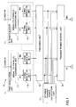
- FIG. 1 illustrates an exemplary arrangement of a radio communication apparatus 10 according to the first embodiment.
- the radio communication apparatus 10 includes a number of modulation units 11 corresponding to the number (N) of users, a precoding unit 12, an optimum transmit power calculation unit 13 and a transmit power control unit 14.
- Each of the modulation units 11 includes a serial-to-parallel conversion unit 111 and signal modulation units 112.
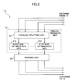
- FIG. 2 illustrates an exemplary arrangement of the optimum transmit power calculation unit 13 according to the first embodiment.
- the optimum transmit power calculation unit 13 includes a parallel processing unit 21 and a merging unit 22.
- the parallel processing unit 21 includes a parallel splitting unit 211 and D sub-optimization units 212.
- the number D may be an arbitrary positive integer.
- the number D may have an upper limit such as the number of streams whose power is to be controlled or the total number of eigenvalues for a channel matrix and may be an arbitrary value smaller than the upper limit.
- BD-ZF channel information based block diagonalization zero-forcing
- any other channel information based MU-MIMO precoder such as ZF, MMSE or DPC, may be used for the precoding.
- another type of precoding of selecting transmit weight vectors from a codebook may be used.
- the serial-to-parallel conversion unit 111 assigns an information signal sequence to be transmitted to the associated user to individual transmit streams.
- the signal modulation units 112 modulate the transmit streams and generate transmit signals s k,j (1 ⁇ k ⁇ N and 1 ⁇ j ⁇ M r ).
- the notation s k,j represents a transmit signal for transmitting the j-th transmit stream for the k-th user.
- a transmit signal may be referred to as a stream or a transmit stream.
- H k ' of size M r ⁇ M r for the k-th user resulting from application of the BD-ZF is defined as follows and is subjected to singular value decomposition (SVD).
- H k ⁇ H k ⁇ W BD - ZF
- k U k ⁇ ⁇ k ⁇ V k
- H ⁇ k ⁇ k , 1 ⁇ 0 ⁇ ⁇ ⁇ 0 ⁇ k , M r
- H represents a Hermitian transpose
- ⁇ k,j represents an eigenvalue of H k ' H H k '.
- the precoding unit 12 derives the matrix W k and supplies components w k,q,j (1 ⁇ q ⁇ M t ) and ⁇ k,j of the matrix W k as transmit weight related information to the optimum transmit power calculation unit 13. Also, the precoding unit 12 supplies the matrix W k and the vector s k to the transmit power control unit 14.
- the diagonal matrix P k with P k , i (1 ⁇ i ⁇ j) represents adjustment amounts for adjusting transmit power levels appropriately.
- an M r -dimensional received signal vector for the k-th user be y k and an M r -dimensional noise vector be n k
- the formula (10) for the optimization problem means maximization of a minimum user capacity among all users.
- the respective channel capacities can be made almost uniform over all the users, which is referred to as Fairness criteria herein.
- the optimization problem can be solved based on an interior point method.
- a barrier parameter r(i) for adjusting values of the barrier function g(P k,j ) is added to the formula (10), and a new optimization problem for maximizing a function without constraints (11) and (12) is solved.
- the parameter i represents the number of step iterations in the interior point method as discussed in detail below. Specifically, it starts with a greater barrier parameter, and the optimum power P k,j is calculated for each barrier parameter. The calculated value is used as an initial value to iterate the process while decreasing the barrier parameter. Once the barrier parameter r(i) reaches a sufficiently small value, the original constrained optimization problem can be solved.
- the parallel splitting unit 211 in the parallel processing unit 21 receives the transmit weight components w k,q,j and the eigenvalues ⁇ k,j supplied from the optimum transmit power calculation unit 13.
- the parallel splitting unit 211 splits a transmit stream into at most D transmit streams depending on bias of the distribution of the eigenvalues ⁇ k , j .
- the number D is equal to the total number of eigenvalues, and the transmit stream is split into multiple transmit streams.
- these transmit streams may be split to the first through tenth sub-optimization units.
- two groups each including five transmit streams may be provided to the first and second sub-optimization units.
- one group of two transmit streams and the other group of eight transmit streams may be provided to the first and second sub-optimization units.
- identical or different power levels may be split to the sub-optimization units. For example, different power levels may be split to the individual sub-optimization units depending on the eigenvalue distribution (magnitude relationship).
- FIG. 3 illustrates exemplary split of sub power optimization problems depending on bias of the eigenvalue distribution. Since the eigenvalue distribution depends on a channel model in an implementation environment, the parallel splitting unit 211 perform division based on the eigenvalue distribution in that model. Also, transmit power levels P k,j are split to the individual sub power optimization problems depending on the bias of the eigenvalue distribution. From the viewpoint of data transmission efficiency, it is desirable that a greater amount of power be assigned to a sub-optimization unit to which a transmit stream associated with a greater eigenvalue belongs.
- FIG. 4 illustrates exemplary arrangements of the sub-optimization unit 212 and the merging unit 22 in the case where the optimization is performed in accordance with the interior point method combined with the steepest descent method.
- the sub-optimization unit 212 and the merging unit 22 each includes an initial power calculation unit 41, a barrier parameter multiplication unit 42, a channel capacity calculation unit 43, a steepest descent processing unit 44 and an iteration unit 45.
- the above elements of the sub-optimization unit 212 and the merging unit 22 are configured to have the same structure and function. This configuration is not limited to the present embodiment, but it may be preferable that the sub-optimization unit 212 and the merging unit 22 have the same structure and function from the viewpoint of simplification of architecture.
- FIG. 5 illustrates an exemplary detailed arrangement of the iteration unit 45 according to the first embodiment.
- the iteration unit 45 includes a post-precoding power calculation unit 51, a constraint determination unit 52, a steepest descent method step size updating unit 53, a steepest descent method convergence determination unit 54, an interior point method convergence determination unit 55 and a barrier parameter updating unit 56.
- the individual sub-optimization units 212 receive transmit weight components w k,q,j and eigenvalues ⁇ k,j corresponding to transmit streams split by the parallel splitting unit 21 in FIG. 2 .
- a set of transmit streams split to the d-th sub-optimization unit 212 for the k-th user be J k d .
- the transmit power level P q d is supplied to the barrier parameter multiplication unit 42.
- the barrier parameter multiplication unit 42 multiplies the barrier function with a barrier parameter r(i).
- the channel capacity calculation unit 43 uses the supplied P k,j , w k,q,j and ⁇ k,j to calculate channel capacities C k for individual users in accordance with the formula (9) and supplies the calculated channel capacities to the steepest descent processing unit 44.
- the steepest descent processing unit 44 optimizes the transmit power levels using the formula (13) associated with the optimization problem using the barrier function in accordance with the steepest descent method.
- the steepest descent method herein is one method for optimization through use of a gradient of an evaluation function as specified in the formula (13).
- the transmit power value P k,j optimized in the steepest descent processing unit 44 is supplied to the iteration unit 45 as described in FIG. 5 .
- the post-precoding power calculation unit 51 computes the transmit power levels P q d for the individual transmit antennas based on the supplied P k,j and w k,q,j and supplies them to the constraint determination unit 52.
- the steepest descent method step size updating unit 53 decreases the step size ⁇ and returns it to the channel capacity calculation unit 43.
- the constraint determination unit 52 iterates the above operations until the condition in the formula (19) is satisfied. If the constraint determination unit 52 determines that any of the conditions in formula (19) is satisfied, the transmit power level P k,j is supplied to the steepest descent method convergence determination unit 54.
- the parameters ⁇ 1 and ⁇ 2 are sufficiently small values. Note that the above conditions are illustrative for convergence conditions for the steepest descent method and any other convergence conditions may be used. In other words, appropriate determination only has to be made as to whether the evaluation function F as specified in the formula (13) reaches an extreme value.
- the steepest descent method convergence determination unit 54 If none of the conditions in the formula (21) is satisfied, the steepest descent method convergence determination unit 54 returns the current transmit power level P k,j to the channel capacity calculation unit 43 and in turn iterates the same operations until any of the conditions in the formulae (21) is satisfied. On the other hand, if any of the conditions is satisfied, the steepest descent method convergence determination unit 54 supplies the current transmit power level P k,j to the interior point method convergence determination unit 55.
- the interior point method convergence determination unit 55 determines whether step iteration convergence conditions for the interior point method as presented below are satisfied, ⁇ r i ⁇ ⁇ 3 min k ⁇ C k d i - min k ⁇ C k d ⁇ i - 1 ⁇ ⁇ 4 where the parameter i represents the number of iterations in the interior point method. Also, the parameters ⁇ 3 and ⁇ 4 are sufficiently small values. Note that the above step iteration convergence conditions for the interior point method are illustrative and any other conditions may be used. In other words, appropriate determination only has to be made as to whether the evaluation function for the power optimization problem as specified in the formula (10) reaches an extreme value.
- the interior point method convergence determination unit 55 determines the current transmit power level P k,j to be an optimum solution at the barrier parameter r(i).
- the barrier parameter updating unit 56 decreases the barrier parameter in accordance with the formula (17).
- the barrier parameter updating unit 56 supplies the P k,j and r(i) to the barrier parameter multiplication unit 42, and the step iteration for the interior point method is reinitiated.
- the interior point method convergence determination unit 55 determines the current transmit power level P k,j to be an optimum solution for the sub-optimization unit 212.
- the optimum solution is supplied from the parallel processing unit 21 to the merging unit 22.
- the merging unit 22 uses the transmit power levels P k,j supplied from the parallel processing unit 21 as initial values to perform optimization in a manner similar to that of the parallel processing unit 21.
- the merging unit 22 includes an initial power calculation unit 41, a barrier parameter multiplication unit 42, a channel capacity calculation unit 43, a steepest descent processing unit 44 and an iteration unit 45 as in the sub-optimization unit 212.
- the merging unit 22 supplies the resultant optimum transmit power level P k,j to the transmit power control unit 14.
- the parameter d is removed from the formulae (16), (19), (21) and (23), and the parameter J k d is replaced with ⁇ 1, 2, ..., M r ⁇ .
- the conditions in the formula (19) may be modified as follows, ⁇ P q ⁇ P max , q P k , j ⁇ 0
- FIG. 6 is a flowchart illustrating operations of the optimum transmit power calculation unit 13 in FIG. 1 .
- an initial value of the barrier parameter r(i), an initial transmit power level P k,j , the maximum number of iterations in the steepest descent method I max and parameters ⁇ 1 through ⁇ 4 are set.
- bias of an eigenvalue distribution for eigenvalues ⁇ k,j supplied to the optimum transmit power calculation unit 13 is used to split transmit streams to the D sub-optimization units.
- the initial values in the steepest descent method and the interior point method are set at step 61, but any other parameters suitable for applied optimization schemes and convergence conditions may be set.
- the individual D sub-optimization units perform the optimization and derive respective optimum solutions for associated transmit streams in the overall transmit stream for further processing.
- transmit power levels P k,j being incoming respective optimum solutions are used as initial transmit power levels for the individual transmit streams to solve the optimum problem for the overall transmit stream.
- the resultant optimum solution P k,j is supplied at step 65.
- FIG. 7 is a flowchart illustrating steps 63, 64 in detail.
- the transmit power levels P q d are derived for individual transmit antennas as stated above.
- the barrier parameter r(i) as specified in the formula (17), an objective function for the new optimization problem, the transmit power level P q d for the d-th transmit stream in the q-th transmit antenna and/or others are provided.
- step 73 respective channel capacities for individual users are calculated.
- a gradient of the objective function F that is, a differential value, is derived based on the calculated channel capacities, and new power levels P k,j are calculated in accordance with the formula (18).
- step 75 respective transmit power levels P q d for the individual transmit antennas are calculated in accordance with the formula (16), and it is determined whether the conditions in the formula (19) are satisfied. If any of the conditions is not satisfied, at step 76, the step size ⁇ is decreased. Then, the updated step size ⁇ is supplied to step 73, and the same operations are iterated until the conditions are satisfied at step 75.
- step 77 it is determined whether convergence conditions in the steepest descent method in the formula (21) are satisfied. If none of the conditions in the formula (21) is satisfied, the transmit power level P k,j is supplied to step 73, and the same operations are iterated until any of the conditions in the formula (21) is satisfied at step 77.
- step 78 it is determined whether step iteration convergence conditions in the interior point method in the formula (23) are satisfied. If none of the convergence conditions in the formula (23) is satisfied, the current transmit power P k,j is determined as an optimum solution at the barrier parameter r(i). At step 79, the barrier parameter is decreased in accordance with the formula (17). Then, the process control returns to step 72, and the step iteration for the interior point method is performed at the transmit power level P k,j and the barrier parameter r(i).
- the current transmit power P k,j is supplied as an optimum solution for step 63 in FIG. 6 .
- the individual transmit power levels P k,j supplied from step 63 are used as initial values to perform steps 71 through 79 for the same optimization as step 63.
- the resultant optimum transmit power level P k,j is supplied at step 65.
- the optimization scheme using the steepest descent method in the interior point method processing is used.
- other suitable optimization schemes may be used for the interior point method processing.
- the transmit power optimization problem can be split into sub transmit power optimization problems in accordance with the configuration and flowchart as illustrated in FIGS. 2 and 6 and respective results can be combined.
- the optimization problem is solved such that channel capacities C k are made uniform over individual users.
- the optimization problem may be solved such that channel capacity C for the overall system is maximized.
- the optimization problem directed to maximize the channel capacity C for the overall system is referred to as Sum-rate criteria herein.
- the solution for that optimization problem is similar to Fairness criteria.
- the power limit values P max,q are illustratively provided for individual transmit antennas.
- transmit antennas may be grouped into several groups, and the power limit values may be provided for the individual groups. Also, in this case, the above optimization scheme is available.
- FIG. 8 illustrates exemplary groups of transmit antennas in a radio communication apparatus.
- the reference symbol L (1 ⁇ 1 ⁇ L) represents the group number
- the reference symbol S 1 represents a set of transmit antenna numbers belonging to the group 1.
- the BD-ZF scheme is illustratively applied for precoding, but the present embodiment can be applied to transmit power optimization problems through use of other precoding schemes.
- multiple transmit antennas are installed on a radio communication apparatus.
- multiple transmit antennas may be separated from a radio communication apparatus and be coupled to the radio communication apparatus in a wired and/or wireless manner.
- FIG. 9 illustrates a radio communication apparatus according to the second embodiment of the present invention.
- a radio communication apparatus 10 is coupled to transmit antenna units 91 each having multiple transmit antennas in a wired and/or wireless manner.
- the radio communication apparatus 10 may operate in a similar manner to that of the first embodiment except that the radio communication apparatus 10 is separated from the transmit antenna units 91.
- the BD-ZF is used for precoding. Respective transmit power levels for individual transmit antennas are constrained to be lower than or equal to a power limit value P max . Also, the barrier function as specified in the formula (14) is used for this simulation. Further, it is assumed that the number M t of transmit antennas is equal to 6, the number N of users is equal to 2, the number M r of user antennas is equal to 3, and three streams are space-multiplexed and transmitted for each user. Also, it is assumed that the power limit value P max is equal to 1/6 for each transmit antenna, and the total usable transmit power is equal to 1.
- the number D of the sub-optimization units is equal to 2.
- 10,000 patterns of MIMO channel matrices are used for optimization, and the results are averaged.
- respective MIMO channels for the users are independent identically distributed (i.i.d.) Rayleigh fading.
- Other parameters are set below. Note that the parameter ⁇ 4 is set to 0 to observe convergence in the present simulation.
- P k ,j (0) P k ,j supplied from the parallel processing unit is used as an initial value.
- r(0): r(i) supplied from the parallel processing unit is used as an initial value.
- ⁇ 0.05
- I max 2000
- ⁇ 1 10 - 6
- ⁇ 2 10 - 11
- ⁇ 3 10 - 17
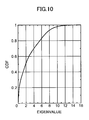
- FIG. 10 illustrates an eigenvalue distribution for all users in the present simulation.
- the horizontal axis represents the magnitude of the eigenvalue ⁇ k,j
- the vertical axis represents the associated cumulative distribution. From the illustration, it can be observed that 80% of all the users have eigenvalues smaller than about 5.5. It is assumed that the parallel splitting unit 211 in FIG. 2 provides the first sub-optimization unit 212 with transmit streams having eigenvalues ⁇ k,j ⁇ 5.5 (upper 20% of transmit streams) and the second sub-optimization unit 212 with transmit streams having eigenvalues ⁇ k,j ⁇ 5.5.
- a transmit power limit value P max 1 in the first sub-optimization unit 212 is set to 0.8 ⁇ P max and a transmit power limit value P max 2 in the second sub-optimization unit 212 is set to 0.2 ⁇ P max in accordance with the Pareto Law.
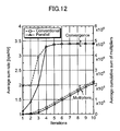
- FIG. 11 illustrates an exemplary comparison of average minimum transmission rates for all users (channel capacity of minimum user channel capacity at step i in the interior point method) between optimization in a conventional scheme without parallel processing and optimization according to the present embodiment.
- the Fairness criteria is used in the optimization.
- the "Conventional" illustrates performances on the optimization in accordance with the conventional scheme without parallel processing.
- FIG. 11 illustrates not only convergence but also the accumulated number of multipliers. Note that the horizontal axis represents the i-th step iteration in the interior point method.
Landscapes
- Engineering & Computer Science (AREA)
- Computer Networks & Wireless Communication (AREA)
- Signal Processing (AREA)
- Mobile Radio Communication Systems (AREA)
- Radio Transmission System (AREA)
Applications Claiming Priority (1)
| Application Number | Priority Date | Filing Date | Title |
|---|---|---|---|
| JP2008125340A JP5241313B2 (ja) | 2008-05-12 | 2008-05-12 | 無線通信装置及び無線通信方法 |
Publications (3)
| Publication Number | Publication Date |
|---|---|
| EP2120501A2 true EP2120501A2 (de) | 2009-11-18 |
| EP2120501A3 EP2120501A3 (de) | 2012-02-29 |
| EP2120501B1 EP2120501B1 (de) | 2015-07-15 |
Family
ID=40937473
Family Applications (1)
| Application Number | Title | Priority Date | Filing Date |
|---|---|---|---|
| EP09251188.0A Not-in-force EP2120501B1 (de) | 2008-05-12 | 2009-04-27 | Funkkommunikationsvorrichtung und Funkkommunikationsverfahren |
Country Status (4)
| Country | Link |
|---|---|
| US (1) | US8095169B2 (de) |
| EP (1) | EP2120501B1 (de) |
| JP (1) | JP5241313B2 (de) |
| CN (1) | CN101583183B (de) |
Families Citing this family (9)
| Publication number | Priority date | Publication date | Assignee | Title |
|---|---|---|---|---|
| JP4801755B2 (ja) * | 2009-04-23 | 2011-10-26 | 株式会社エヌ・ティ・ティ・ドコモ | 無線通信装置及び方法 |
| JP5727201B2 (ja) * | 2010-11-24 | 2015-06-03 | シャープ株式会社 | 基地局装置及び通信方法 |
| EP2984801A1 (de) * | 2013-04-09 | 2016-02-17 | Interdigital Patent Holdings, Inc. | Gemeinsame vorcodierung und multivariate backhaulkompression in abwärtsrichtung von cloud-funkzugangsnetzen |
| US9450657B2 (en) * | 2013-08-28 | 2016-09-20 | Nec Corporation | Low-complexity precoder design for large-scale MIMO communication systems |
| US9503166B2 (en) * | 2015-03-17 | 2016-11-22 | Futurewei Technologies, Inc. | System and method for coordinated MIMO switching (CMS) in TDD/FDD-LTE |
| US9973251B1 (en) * | 2015-08-05 | 2018-05-15 | Mitsubishi Electric Corporation | Radio transmission apparatus |
| US10203410B2 (en) | 2017-05-02 | 2019-02-12 | Honeywell International Inc. | Probabilistic weather severity estimation system |
| CN110505677B (zh) * | 2018-05-18 | 2023-07-07 | 华为技术有限公司 | 基于多站点协作的数据传输方法和装置 |
| CN111867030B (zh) * | 2020-06-17 | 2023-09-29 | 浙江工业大学 | 基于粒子群优化的射频能量源布置与发射功率设置方法 |
Citations (1)
| Publication number | Priority date | Publication date | Assignee | Title |
|---|---|---|---|---|
| JP2008125340A (ja) | 2006-11-14 | 2008-05-29 | Kt Corp | ケーブル撤去装置 |
Family Cites Families (12)
| Publication number | Priority date | Publication date | Assignee | Title |
|---|---|---|---|---|
| CN1323503C (zh) * | 2001-11-06 | 2007-06-27 | 中兴通讯股份有限公司 | 一种阵列天线全自适应权值更新的方法及装置 |
| CN1234221C (zh) * | 2003-12-31 | 2005-12-28 | 清华大学 | 用于无线通信的多用户二维联合互补扩频码的编码方法 |
| JP4260653B2 (ja) * | 2004-03-01 | 2009-04-30 | 日本電信電話株式会社 | 空間多重伝送用送信装置 |
| KR101124932B1 (ko) * | 2005-05-30 | 2012-03-28 | 삼성전자주식회사 | 어레이 안테나를 이용하는 이동 통신 시스템에서의 데이터송/수신 장치 및 방법 |
| JP4504293B2 (ja) * | 2005-09-29 | 2010-07-14 | 株式会社東芝 | 複数アンテナを備えた無線通信装置および無線通信システム、無線通信方法 |
| CN1941661B (zh) * | 2005-09-30 | 2011-04-06 | 松下电器产业株式会社 | 多天线输入和输出系统中的全复用分集方法 |
| US7715803B2 (en) * | 2005-12-20 | 2010-05-11 | Samsung Electronics Co., Ltd. | Methods and apparatus for constant-power loading asymmetric antenna configuration |
| WO2007136211A2 (en) * | 2006-05-19 | 2007-11-29 | Lg Electronics Inc. | A method of utilizing and manipulating wireless resources for efficient and effective wireless communication |
| US7715485B1 (en) * | 2007-01-08 | 2010-05-11 | L-3 Communications, Corp. | MIMO communication using interference cancellation and unequal transmit power distribution |
| WO2009099287A1 (en) * | 2008-02-04 | 2009-08-13 | Samsung Electronics Co., Ltd. | Control and data multiplexing in communication systems |
| JP5340634B2 (ja) * | 2008-05-12 | 2013-11-13 | 株式会社エヌ・ティ・ティ・ドコモ | 無線通信装置及び無線通信方法 |
| JP5173573B2 (ja) * | 2008-05-12 | 2013-04-03 | 株式会社エヌ・ティ・ティ・ドコモ | 無線通信装置及び無線通信方法 |
-
2008
- 2008-05-12 JP JP2008125340A patent/JP5241313B2/ja active Active
-
2009
- 2009-04-27 EP EP09251188.0A patent/EP2120501B1/de not_active Not-in-force
- 2009-04-29 US US12/432,174 patent/US8095169B2/en not_active Expired - Fee Related
- 2009-05-12 CN CN2009101408214A patent/CN101583183B/zh not_active Expired - Fee Related
Patent Citations (1)
| Publication number | Priority date | Publication date | Assignee | Title |
|---|---|---|---|---|
| JP2008125340A (ja) | 2006-11-14 | 2008-05-29 | Kt Corp | ケーブル撤去装置 |
Non-Patent Citations (3)
| Title |
|---|
| G.J. FOSCHINI; K. KARAKAYALI; R.A. VALENZUELA: "Coordinating multiple antenna cellular networks to achieve enormous spectral efficiency", IEE PROCEEDINGS COMMUNICATIONS, vol. 153, no. 4, August 2006 (2006-08-01), pages 548 - 555 |
| S. LIU ET AL.: "Multi-level zero-forcing method for multiuser downlink system with per-antenna power constraint", VTC 2007-SPRING, April 2007 (2007-04-01), pages 2248 - 2252 |
| W. YU; T. LAN: "Transmitter optimization for the multi-antenna downlink with per-antenna power constraints", IEEE TRANS., SIGNAL PROCESSING, June 2007 (2007-06-01), pages 2646 - 2660 |
Also Published As
| Publication number | Publication date |
|---|---|
| JP2009278203A (ja) | 2009-11-26 |
| CN101583183B (zh) | 2012-02-01 |
| US8095169B2 (en) | 2012-01-10 |
| CN101583183A (zh) | 2009-11-18 |
| EP2120501B1 (de) | 2015-07-15 |
| US20090280855A1 (en) | 2009-11-12 |
| JP5241313B2 (ja) | 2013-07-17 |
| EP2120501A3 (de) | 2012-02-29 |
Similar Documents
| Publication | Publication Date | Title |
|---|---|---|
| US8224369B2 (en) | Radio communication apparatus and radio communication method | |
| EP2244390B1 (de) | Funkkommunikationsvorrichtung und -verfahren | |
| US8385861B2 (en) | Radio communication apparatus and radio communication method | |
| EP2120501B1 (de) | Funkkommunikationsvorrichtung und Funkkommunikationsverfahren | |
| Chae et al. | Coordinated beamforming with limited feedback in the MIMO broadcast channel | |
| EP1775857B1 (de) | Verfahren und Vorrichtung zum Senden/Empfangen von Daten in einem Mehrbenutzer, Mehrantennen Kommunikationssystem | |
| EP1775855B1 (de) | Verfahren und Vorrichtung zum Senden/Empfangen von Daten in einem Mehrbenutzer, Mehrantennen Kommunikationssystem | |
| CN101741446B (zh) | 多输入多输出方法和装置 | |
| EP2832001B1 (de) | System und verfahren zur nichtlinearen mu-mimo-downlink-kanal-vorcodierung mit einem beliebigen vorcodierer | |
| Qiu et al. | A covariance-based hybrid channel feedback in FDD massive MIMO systems | |
| Chae et al. | Coordinated beamforming for multiuser MIMO systems with limited feedforward | |
| Soysal et al. | Transmit directions and optimality of beamforming in MIMO-MAC with partial CSI at the transmitters | |
| Kudo et al. | User selection method for block diagonalization in multiuser MIMO systems | |
| Kudo et al. | CSI estimation method based on random beamforming for massive number of transmit antenna systems | |
| Mishra et al. | Squared norm based joint user scheduling and antenna selection in massive MIMO system | |
| Huang et al. | Technical report on efficient integration of dynamic tdd with massive mimo | |
| Khachan et al. | Joint transmitter-receiver optimization for downlink multiuser MIMO communications | |
| Zheng et al. | An efficient user selection algorithm for zero-forcing beamforming in downlink multiuser MIMO systems | |
| Sacristán-Murga et al. | Precoding and feedback schemes for a MIMO backhaul link in the presence of interference | |
| Riahi et al. | Block diagonalization with interference control for energy efficient downlink | |
| Ohwatari et al. | Reduced-complexity transmit power optimization techniques for multiuser MIMO with per-antenna power constraint | |
| Lee et al. | Cooperative transmission with partial channel information in multi-user MISO wireless systems | |
| Tran et al. | Low-complexity scheduling algorithms for successive zero-forcing dirty paper coded systems |
Legal Events
| Date | Code | Title | Description |
|---|---|---|---|
| PUAI | Public reference made under article 153(3) epc to a published international application that has entered the european phase |
Free format text: ORIGINAL CODE: 0009012 |
|
| 17P | Request for examination filed |
Effective date: 20090519 |
|
| AK | Designated contracting states |
Kind code of ref document: A2 Designated state(s): AT BE BG CH CY CZ DE DK EE ES FI FR GB GR HR HU IE IS IT LI LT LU LV MC MK MT NL NO PL PT RO SE SI SK TR |
|
| PUAL | Search report despatched |
Free format text: ORIGINAL CODE: 0009013 |
|
| AK | Designated contracting states |
Kind code of ref document: A3 Designated state(s): AT BE BG CH CY CZ DE DK EE ES FI FR GB GR HR HU IE IS IT LI LT LU LV MC MK MT NL NO PL PT RO SE SI SK TR |
|
| AX | Request for extension of the european patent |
Extension state: AL BA RS |
|
| RIC1 | Information provided on ipc code assigned before grant |
Ipc: H04W 52/34 20090101AFI20120126BHEP Ipc: H04B 7/04 20060101ALI20120126BHEP Ipc: H04B 7/06 20060101ALI20120126BHEP |
|
| GRAP | Despatch of communication of intention to grant a patent |
Free format text: ORIGINAL CODE: EPIDOSNIGR1 |
|
| INTG | Intention to grant announced |
Effective date: 20150210 |
|
| GRAS | Grant fee paid |
Free format text: ORIGINAL CODE: EPIDOSNIGR3 |
|
| GRAA | (expected) grant |
Free format text: ORIGINAL CODE: 0009210 |
|
| AK | Designated contracting states |
Kind code of ref document: B1 Designated state(s): AT BE BG CH CY CZ DE DK EE ES FI FR GB GR HR HU IE IS IT LI LT LU LV MC MK MT NL NO PL PT RO SE SI SK TR |
|
| REG | Reference to a national code |
Ref country code: CH Ref legal event code: EP Ref country code: GB Ref legal event code: FG4D |
|
| RIN1 | Information on inventor provided before grant (corrected) |
Inventor name: HAGIWARA, JUNICHIRO Inventor name: OOYA, TOMOYUKI Inventor name: BENJEBBOUR, ANASS Inventor name: OHWATARI, YUSUKE |
|
| REG | Reference to a national code |
Ref country code: IE Ref legal event code: FG4D |
|
| REG | Reference to a national code |
Ref country code: AT Ref legal event code: REF Ref document number: 737308 Country of ref document: AT Kind code of ref document: T Effective date: 20150815 |
|
| REG | Reference to a national code |
Ref country code: DE Ref legal event code: R096 Ref document number: 602009032212 Country of ref document: DE |
|
| REG | Reference to a national code |
Ref country code: AT Ref legal event code: MK05 Ref document number: 737308 Country of ref document: AT Kind code of ref document: T Effective date: 20150715 |
|
| REG | Reference to a national code |
Ref country code: NL Ref legal event code: MP Effective date: 20150715 |
|
| REG | Reference to a national code |
Ref country code: LT Ref legal event code: MG4D |
|
| PG25 | Lapsed in a contracting state [announced via postgrant information from national office to epo] |
Ref country code: GR Free format text: LAPSE BECAUSE OF FAILURE TO SUBMIT A TRANSLATION OF THE DESCRIPTION OR TO PAY THE FEE WITHIN THE PRESCRIBED TIME-LIMIT Effective date: 20151016 Ref country code: FI Free format text: LAPSE BECAUSE OF FAILURE TO SUBMIT A TRANSLATION OF THE DESCRIPTION OR TO PAY THE FEE WITHIN THE PRESCRIBED TIME-LIMIT Effective date: 20150715 Ref country code: LT Free format text: LAPSE BECAUSE OF FAILURE TO SUBMIT A TRANSLATION OF THE DESCRIPTION OR TO PAY THE FEE WITHIN THE PRESCRIBED TIME-LIMIT Effective date: 20150715 Ref country code: NO Free format text: LAPSE BECAUSE OF FAILURE TO SUBMIT A TRANSLATION OF THE DESCRIPTION OR TO PAY THE FEE WITHIN THE PRESCRIBED TIME-LIMIT Effective date: 20151015 Ref country code: LV Free format text: LAPSE BECAUSE OF FAILURE TO SUBMIT A TRANSLATION OF THE DESCRIPTION OR TO PAY THE FEE WITHIN THE PRESCRIBED TIME-LIMIT Effective date: 20150715 |
|
| PG25 | Lapsed in a contracting state [announced via postgrant information from national office to epo] |
Ref country code: SE Free format text: LAPSE BECAUSE OF FAILURE TO SUBMIT A TRANSLATION OF THE DESCRIPTION OR TO PAY THE FEE WITHIN THE PRESCRIBED TIME-LIMIT Effective date: 20150715 Ref country code: PL Free format text: LAPSE BECAUSE OF FAILURE TO SUBMIT A TRANSLATION OF THE DESCRIPTION OR TO PAY THE FEE WITHIN THE PRESCRIBED TIME-LIMIT Effective date: 20150715 Ref country code: HR Free format text: LAPSE BECAUSE OF FAILURE TO SUBMIT A TRANSLATION OF THE DESCRIPTION OR TO PAY THE FEE WITHIN THE PRESCRIBED TIME-LIMIT Effective date: 20150715 Ref country code: AT Free format text: LAPSE BECAUSE OF FAILURE TO SUBMIT A TRANSLATION OF THE DESCRIPTION OR TO PAY THE FEE WITHIN THE PRESCRIBED TIME-LIMIT Effective date: 20150715 Ref country code: PT Free format text: LAPSE BECAUSE OF FAILURE TO SUBMIT A TRANSLATION OF THE DESCRIPTION OR TO PAY THE FEE WITHIN THE PRESCRIBED TIME-LIMIT Effective date: 20151116 Ref country code: ES Free format text: LAPSE BECAUSE OF FAILURE TO SUBMIT A TRANSLATION OF THE DESCRIPTION OR TO PAY THE FEE WITHIN THE PRESCRIBED TIME-LIMIT Effective date: 20150715 |
|
| REG | Reference to a national code |
Ref country code: DE Ref legal event code: R097 Ref document number: 602009032212 Country of ref document: DE |
|
| PG25 | Lapsed in a contracting state [announced via postgrant information from national office to epo] |
Ref country code: SK Free format text: LAPSE BECAUSE OF FAILURE TO SUBMIT A TRANSLATION OF THE DESCRIPTION OR TO PAY THE FEE WITHIN THE PRESCRIBED TIME-LIMIT Effective date: 20150715 Ref country code: DK Free format text: LAPSE BECAUSE OF FAILURE TO SUBMIT A TRANSLATION OF THE DESCRIPTION OR TO PAY THE FEE WITHIN THE PRESCRIBED TIME-LIMIT Effective date: 20150715 Ref country code: EE Free format text: LAPSE BECAUSE OF FAILURE TO SUBMIT A TRANSLATION OF THE DESCRIPTION OR TO PAY THE FEE WITHIN THE PRESCRIBED TIME-LIMIT Effective date: 20150715 Ref country code: IT Free format text: LAPSE BECAUSE OF FAILURE TO SUBMIT A TRANSLATION OF THE DESCRIPTION OR TO PAY THE FEE WITHIN THE PRESCRIBED TIME-LIMIT Effective date: 20150715 Ref country code: CZ Free format text: LAPSE BECAUSE OF FAILURE TO SUBMIT A TRANSLATION OF THE DESCRIPTION OR TO PAY THE FEE WITHIN THE PRESCRIBED TIME-LIMIT Effective date: 20150715 |
|
| PLBE | No opposition filed within time limit |
Free format text: ORIGINAL CODE: 0009261 |
|
| STAA | Information on the status of an ep patent application or granted ep patent |
Free format text: STATUS: NO OPPOSITION FILED WITHIN TIME LIMIT |
|
| PG25 | Lapsed in a contracting state [announced via postgrant information from national office to epo] |
Ref country code: RO Free format text: LAPSE BECAUSE OF FAILURE TO SUBMIT A TRANSLATION OF THE DESCRIPTION OR TO PAY THE FEE WITHIN THE PRESCRIBED TIME-LIMIT Effective date: 20150715 |
|
| 26N | No opposition filed |
Effective date: 20160418 |
|
| PG25 | Lapsed in a contracting state [announced via postgrant information from national office to epo] |
Ref country code: IS Free format text: LAPSE BECAUSE OF FAILURE TO SUBMIT A TRANSLATION OF THE DESCRIPTION OR TO PAY THE FEE WITHIN THE PRESCRIBED TIME-LIMIT Effective date: 20150715 |
|
| PG25 | Lapsed in a contracting state [announced via postgrant information from national office to epo] |
Ref country code: SI Free format text: LAPSE BECAUSE OF FAILURE TO SUBMIT A TRANSLATION OF THE DESCRIPTION OR TO PAY THE FEE WITHIN THE PRESCRIBED TIME-LIMIT Effective date: 20150715 Ref country code: BE Free format text: LAPSE BECAUSE OF NON-PAYMENT OF DUE FEES Effective date: 20160430 |
|
| REG | Reference to a national code |
Ref country code: CH Ref legal event code: PL |
|
| PG25 | Lapsed in a contracting state [announced via postgrant information from national office to epo] |
Ref country code: BE Free format text: LAPSE BECAUSE OF FAILURE TO SUBMIT A TRANSLATION OF THE DESCRIPTION OR TO PAY THE FEE WITHIN THE PRESCRIBED TIME-LIMIT Effective date: 20150715 Ref country code: LU Free format text: LAPSE BECAUSE OF FAILURE TO SUBMIT A TRANSLATION OF THE DESCRIPTION OR TO PAY THE FEE WITHIN THE PRESCRIBED TIME-LIMIT Effective date: 20160427 |
|
| REG | Reference to a national code |
Ref country code: IE Ref legal event code: MM4A |
|
| REG | Reference to a national code |
Ref country code: FR Ref legal event code: ST Effective date: 20161230 |
|
| PG25 | Lapsed in a contracting state [announced via postgrant information from national office to epo] |
Ref country code: FR Free format text: LAPSE BECAUSE OF NON-PAYMENT OF DUE FEES Effective date: 20160502 Ref country code: CH Free format text: LAPSE BECAUSE OF NON-PAYMENT OF DUE FEES Effective date: 20160430 Ref country code: LI Free format text: LAPSE BECAUSE OF NON-PAYMENT OF DUE FEES Effective date: 20160430 |
|
| PG25 | Lapsed in a contracting state [announced via postgrant information from national office to epo] |
Ref country code: IE Free format text: LAPSE BECAUSE OF NON-PAYMENT OF DUE FEES Effective date: 20160427 |
|
| PG25 | Lapsed in a contracting state [announced via postgrant information from national office to epo] |
Ref country code: NL Free format text: LAPSE BECAUSE OF FAILURE TO SUBMIT A TRANSLATION OF THE DESCRIPTION OR TO PAY THE FEE WITHIN THE PRESCRIBED TIME-LIMIT Effective date: 20150715 |
|
| PGFP | Annual fee paid to national office [announced via postgrant information from national office to epo] |
Ref country code: GB Payment date: 20180329 Year of fee payment: 10 |
|
| PG25 | Lapsed in a contracting state [announced via postgrant information from national office to epo] |
Ref country code: HU Free format text: LAPSE BECAUSE OF FAILURE TO SUBMIT A TRANSLATION OF THE DESCRIPTION OR TO PAY THE FEE WITHIN THE PRESCRIBED TIME-LIMIT; INVALID AB INITIO Effective date: 20090427 Ref country code: CY Free format text: LAPSE BECAUSE OF FAILURE TO SUBMIT A TRANSLATION OF THE DESCRIPTION OR TO PAY THE FEE WITHIN THE PRESCRIBED TIME-LIMIT Effective date: 20150715 |
|
| PG25 | Lapsed in a contracting state [announced via postgrant information from national office to epo] |
Ref country code: MC Free format text: LAPSE BECAUSE OF FAILURE TO SUBMIT A TRANSLATION OF THE DESCRIPTION OR TO PAY THE FEE WITHIN THE PRESCRIBED TIME-LIMIT Effective date: 20150715 Ref country code: TR Free format text: LAPSE BECAUSE OF FAILURE TO SUBMIT A TRANSLATION OF THE DESCRIPTION OR TO PAY THE FEE WITHIN THE PRESCRIBED TIME-LIMIT Effective date: 20150715 Ref country code: MT Free format text: LAPSE BECAUSE OF NON-PAYMENT OF DUE FEES Effective date: 20160430 Ref country code: MK Free format text: LAPSE BECAUSE OF FAILURE TO SUBMIT A TRANSLATION OF THE DESCRIPTION OR TO PAY THE FEE WITHIN THE PRESCRIBED TIME-LIMIT Effective date: 20150715 |
|
| PG25 | Lapsed in a contracting state [announced via postgrant information from national office to epo] |
Ref country code: BG Free format text: LAPSE BECAUSE OF FAILURE TO SUBMIT A TRANSLATION OF THE DESCRIPTION OR TO PAY THE FEE WITHIN THE PRESCRIBED TIME-LIMIT Effective date: 20150715 |
|
| PGFP | Annual fee paid to national office [announced via postgrant information from national office to epo] |
Ref country code: DE Payment date: 20180417 Year of fee payment: 10 |
|
| REG | Reference to a national code |
Ref country code: DE Ref legal event code: R119 Ref document number: 602009032212 Country of ref document: DE |
|
| GBPC | Gb: european patent ceased through non-payment of renewal fee |
Effective date: 20190427 |
|
| PG25 | Lapsed in a contracting state [announced via postgrant information from national office to epo] |
Ref country code: DE Free format text: LAPSE BECAUSE OF NON-PAYMENT OF DUE FEES Effective date: 20191101 Ref country code: GB Free format text: LAPSE BECAUSE OF NON-PAYMENT OF DUE FEES Effective date: 20190427 |