EP2119951A2 - Lubricant supply device - Google Patents
Lubricant supply device Download PDFInfo
- Publication number
- EP2119951A2 EP2119951A2 EP09005883A EP09005883A EP2119951A2 EP 2119951 A2 EP2119951 A2 EP 2119951A2 EP 09005883 A EP09005883 A EP 09005883A EP 09005883 A EP09005883 A EP 09005883A EP 2119951 A2 EP2119951 A2 EP 2119951A2
- Authority
- EP
- European Patent Office
- Prior art keywords
- pump
- supply device
- lubricant
- lubricant supply
- shaft
- Prior art date
- Legal status (The legal status is an assumption and is not a legal conclusion. Google has not performed a legal analysis and makes no representation as to the accuracy of the status listed.)
- Withdrawn
Links
- 239000000314 lubricant Substances 0.000 title claims abstract description 49
- 238000005461 lubrication Methods 0.000 description 11
- 239000004519 grease Substances 0.000 description 2
- 240000006829 Ficus sundaica Species 0.000 description 1
- 240000002834 Paulownia tomentosa Species 0.000 description 1
- 235000010678 Paulownia tomentosa Nutrition 0.000 description 1
- 230000006835 compression Effects 0.000 description 1
- 238000007906 compression Methods 0.000 description 1
- 238000010276 construction Methods 0.000 description 1
- 230000008878 coupling Effects 0.000 description 1
- 238000010168 coupling process Methods 0.000 description 1
- 238000005859 coupling reaction Methods 0.000 description 1
- 238000010586 diagram Methods 0.000 description 1
- 239000012530 fluid Substances 0.000 description 1
- 238000012423 maintenance Methods 0.000 description 1
- 238000004519 manufacturing process Methods 0.000 description 1
- 230000000750 progressive effect Effects 0.000 description 1
- 238000005086 pumping Methods 0.000 description 1
Images


Classifications
-
- F—MECHANICAL ENGINEERING; LIGHTING; HEATING; WEAPONS; BLASTING
- F16—ENGINEERING ELEMENTS AND UNITS; GENERAL MEASURES FOR PRODUCING AND MAINTAINING EFFECTIVE FUNCTIONING OF MACHINES OR INSTALLATIONS; THERMAL INSULATION IN GENERAL
- F16N—LUBRICATING
- F16N11/00—Arrangements for supplying grease from a stationary reservoir or the equivalent in or on the machine or member to be lubricated; Grease cups
- F16N11/08—Arrangements for supplying grease from a stationary reservoir or the equivalent in or on the machine or member to be lubricated; Grease cups with mechanical drive, other than directly by springs or weights
-
- F—MECHANICAL ENGINEERING; LIGHTING; HEATING; WEAPONS; BLASTING
- F16—ENGINEERING ELEMENTS AND UNITS; GENERAL MEASURES FOR PRODUCING AND MAINTAINING EFFECTIVE FUNCTIONING OF MACHINES OR INSTALLATIONS; THERMAL INSULATION IN GENERAL
- F16N—LUBRICATING
- F16N13/00—Lubricating-pumps
-
- F—MECHANICAL ENGINEERING; LIGHTING; HEATING; WEAPONS; BLASTING
- F16—ENGINEERING ELEMENTS AND UNITS; GENERAL MEASURES FOR PRODUCING AND MAINTAINING EFFECTIVE FUNCTIONING OF MACHINES OR INSTALLATIONS; THERMAL INSULATION IN GENERAL
- F16N—LUBRICATING
- F16N7/00—Arrangements for supplying oil or unspecified lubricant from a stationary reservoir or the equivalent in or on the machine or member to be lubricated
- F16N7/14—Arrangements for supplying oil or unspecified lubricant from a stationary reservoir or the equivalent in or on the machine or member to be lubricated the lubricant being conveyed from the reservoir by mechanical means
- F16N7/16—Arrangements for supplying oil or unspecified lubricant from a stationary reservoir or the equivalent in or on the machine or member to be lubricated the lubricant being conveyed from the reservoir by mechanical means the oil being carried up by a lifting device
Definitions
- the invention relates to a lubricant supply device having a lubricant reservoir, in the bottom region of which is a lubricant driven by a motor, the transport element delivering the lubricant to a pump which delivers the lubricant under increased pressure to a lubricant line.
- a device of this kind is for example from the EP 0 009 908 B1 known.
- a device for pumping a lubricant is described in which from a container by means of a screw conveyor, the medium to be delivered is moved into the region of a pump, which then brings it to a desired pressure.
- the auger and the pump each have separate drives.
- the invention is therefore based on the object , a device of the type mentioned in such a way that with only a single drive, the conveying of the lubricant and the pressurization of the same can take place, with a simple construction with a compact design is possible.
- Another essential objective is that a modular design of the device is to be achieved, which in particular makes it possible to carry out a simple assembly and maintenance with easy replacement of components.
- the solution of this object by the invention is characterized in that the conveying element comprises a shaft driven by the motor, around which extend funding, wherein the one axial end of the shaft rotatably connected to a shaft portion of the pump, so that the motor both can drive the conveyor element as well as the pump.
- the conveying element is designed as a screw conveyor, in which a conveying means in the form of at least one helix extends around the shaft.
- the shaft may extend beyond the axial extent of the at least one flight.
- the shaft and the shaft part of the pump are particularly preferably arranged coaxially with each other and non-rotatably connected to each other via a positive connection.
- the positive connection is the only connection between the shaft and the shaft part of the pump.
- the pump is preferably designed as a radial piston pump with at least one radial piston unit. It can also be arranged a plurality of radial piston units around the circumference of the shaft part of the pump. Particularly preferred between 2 and 10 radial piston units arranged equidistant around the circumference of the shaft portion of the pump. All radial piston units can be driven by an eccentric, which is rotatably connected to the shaft part of the pump. Furthermore, it can be provided that all radial piston units are biased with a spring element so that they occupy a defined position without external force. Alternatively, however, it is also possible to provide positive guidance of the pistons.
- the motor can be driven electrically, hydraulically or pneumatically.
- the lubricant line preferably comprises a ring line, which is supplied by all radial piston units with pressurized lubricant. Between a radial piston unit and the ring line, a check valve may be arranged.
- the ring line can be connected to a pressure relief valve.
- the ring line is connected according to a preferred embodiment of the invention with at least one directional control valve.
- a lubricant supply device 1 can be seen, with the grease or oil can be promoted as a lubricant.
- the device 1 is characterized a modular design and can be designed for different lubrication systems, in particular for a two-line centralized lubrication system, for a single-line centralized lubrication system or for a progressive lubrication system.
- the device 1 has a receptacle 2 for lubricant (oil or grease) and is preferably made cylindrical; but it is also possible a square basic shape.
- a motor 3 drives the shaft 7 of a conveyor element 4 in the form of a screw conveyor.
- a worm gear 8, which acts as a conveyor, extends helically around the shaft 7 in a known manner and promotes the rotation of the shaft 7 lubricant.
- a pump 5 is arranged in the form of a radial piston pump.
- the pump 5 has a shaft part 9, which is rotatably coupled to the shaft 7.
- the rotationally fixed connection 16 (s. Fig. 1 ) carried out so that the torque is transmitted from the shaft 7 to the shaft part 9 exclusively by a positive coupling.
- the positive connection 16 can be a radially extending groove 17 (eg in the shaft part 9) into which a congruently shaped projection (eg in the shaft) engages.
- the connection 16 works alone on a positive basis.
- the pump 5 is designed as a radial piston pump, ie, there are several radial piston units 10 equidistant around the circumference of the shaft part 9 of the pump 5 around which are actuated by an eccentric 11 which is rotatably connected to the shaft part 9 of the pump 5.
- the pump 5 is equipped with a plurality of pump elements in the form of the radial piston units 10, wherein the piston stroke movement is caused by the rotating eccentric 11.
- the piston return (suction phase) can be done by compression springs or positively driven.
- Each radial piston unit conveys the medium via a check valve 13 in a ring line 12 (s. FIGS. 4 to 10 ).
- a protection of the lubricant line 6 against overpressure takes place by a pressure relief valve 14th
- Fig. 4 is out of the ring line 12 per a pressure line to 3/2-way valve connections of a directional control valve 15 out (port “A” in Fig. 4/5 ).
- the valve connections "B” in Fig. 4/5 lead to a container (T).
- Valve connections "C” lead to a pump outlet A / P or B / P.
- Other pump connections are the manometer connections MA and MB and a measuring port M or a vent.
- Fig. 4/5 is a Zweitechnischszentralschmiersystem with two reversing valves in the form of two 3/2-way valves provided.
- the valve 18 is switched, the promotion takes place at output A / P.
- valve 19 is not switched, the output B / R connects to tank T (depressurised).
- the valve 19 is switched, the promotion takes place at output B / R.
- the valve 18 is not switched, the output A / P connects to the tank T (depressurized).
- the valves must be switched alternately for this application (delivery at A / P leads to B / R without pressure in container, delivery at B / R leads to A / P without pressure in container).
- Fig. 6/7 is a two-line centralized lubrication system without attached 3/2-way valves shown. Instead of two valves here two baffles 20 and 21 are provided. A Zweitechnischtechnischtechnisch must be installed separately after the pump 5 in the two main lines. Port A / P is the pressure port for the fluid being pumped, port B / R is the port port for pressure relief.
- Fig. 8/9 is a single-line centralized lubrication system with a mounted 3/2-way valve shown. If the valve 18 is switched, the promotion takes place at output A / P. When valve 18 is not switched, output A / P is connected to tank T (depressurized). The valve connections of the valve 19 from Fig. 5 are in the solution according to Fig. 9 closed with a closure plate 22. The output B / R is closed.
- Fig. 10/11 is a centralized lubrication system without attached 3/2-way valves provided.
- a baffle 23 At the connection for the valve 18 according to Fig. 5 is in the solution according to Fig. 11 a baffle 23 and the connection for the valve 19 according to Fig. 5 a closure plate 24 is provided. The entire promotion takes place at exit A / P. The connection B / R is closed.
- the motor 3 is a geared motor with in particular electric, hydraulic or pneumatic drive.
- the screw conveyor 4 promotes by the rotation of the motor 3 medium to the pump 5 and drives these at the same time.
- the receptacle 2 is preferably designed in container sizes for receiving 15, 30 or 60 kg of lubricant.
- the proposed invention is characterized in that the arrangement of motor, screw conveyor and pump is modular. These elements are preferably coupled only form-fitting, ie they are plugged together and not positively connected to each other. This allows easy disassembly or a simple exchange of pump and motor without disassembly of the other components. This modular design can be easily replaced afterwards pump or motor / gearbox to achieve other power ranges.
- the pump 5 can - as stated above - by different equipment (1 time 3/2-way valve or 2 times 3/2-way valve or no 3/2-way valve) pressurize the output lines or as Return line serve.
Abstract
Description
Die Erfindung betrifft eine Schmiermittelversorgungsvorrichtung, die einen Aufnahmebehälter für Schmiermittel aufweist, in dessen Bodenbereich sich ein von einem Motor angetriebenes Förderelement für Schmiermittel befindet, wobei das Förderelement das Schmiermittel zu einer Pumpe fördert, die das Schmiermittel unter erhöhtem Druck in eine Schmiermittelleitung fördert.The invention relates to a lubricant supply device having a lubricant reservoir, in the bottom region of which is a lubricant driven by a motor, the transport element delivering the lubricant to a pump which delivers the lubricant under increased pressure to a lubricant line.
Eine Vorrichtung dieser Art ist beispielsweise aus der
Aus der
Der Erfindung liegt daher die Aufgabe zu Grunde, eine Vorrichtung der eingangs genannten Art so fortzubilden, dass mit nur einem einzigen Antrieb das Fördern des Schmiermittels und das Unter-Druck-Setzen desselben erfolgen kann, wobei eine einfache Konstruktion mit einem kompakten Aufbau ermöglicht wird. Eine weitere wesentliche Zielsetzung ist, dass eine modulartige Bauweise der Vorrichtung erreicht werden soll, die es insbesondere ermöglicht, eine einfache Montage und Wartung mit problemlosem Austausch von Komponenten vornehmen zu können.The invention is therefore based on the object , a device of the type mentioned in such a way that with only a single drive, the conveying of the lubricant and the pressurization of the same can take place, with a simple construction with a compact design is possible. Another essential objective is that a modular design of the device is to be achieved, which in particular makes it possible to carry out a simple assembly and maintenance with easy replacement of components.
Die Lösung dieser Aufgabe durch die Erfindung ist dadurch gekennzeichnet, dass das Förderelement eine von dem Motor angetriebene Welle umfasst, um die herum sich Fördermittel erstrecken, wobei das eine axiale Ende der Welle mit einem Wellenteil der Pumpe drehfest verbunden ist, so dass der Motor sowohl das Förderelement als auch die Pumpe antreiben kann.The solution of this object by the invention is characterized in that the conveying element comprises a shaft driven by the motor, around which extend funding, wherein the one axial end of the shaft rotatably connected to a shaft portion of the pump, so that the motor both can drive the conveyor element as well as the pump.
Dabei ist bevorzugt vorgesehen, dass das Förderelement als Förderschnecke ausgebildet ist, bei dem sich um die Welle herum ein Fördermittel in Form mindestens eines Schneckenganges erstreckt. Die Welle kann sich dabei über die axiale Ausdehnung des mindestens einen Schneckenganges hinaus erstrecken.In this case, it is preferably provided that the conveying element is designed as a screw conveyor, in which a conveying means in the form of at least one helix extends around the shaft. The shaft may extend beyond the axial extent of the at least one flight.
Die Welle und das Wellenteil der Pumpe sind besonders bevorzugt koaxial zueinander angeordnet und über eine formschlüssige Verbindung drehfest miteinander verbunden. In diesem Falle ist es vorteilhaft, wenn die formschlüssige Verbindung die einzige Verbindung zwischen der Welle und dem Wellenteil der Pumpe ist.The shaft and the shaft part of the pump are particularly preferably arranged coaxially with each other and non-rotatably connected to each other via a positive connection. In this case, it is advantageous if the positive connection is the only connection between the shaft and the shaft part of the pump.
Die Pumpe ist vorzugsweise als Radialkolbenpumpe mit mindestens einer Radialkolbeneinheit ausgebildet. Es können auch mehrere Radialkolbeneinheiten um den Umfang des Wellenteils der Pumpe angeordnet werden. Besonders bevorzugt sind zwischen 2 und 10 Radialkolbeneinheiten um den Umfang des Wellenteils der Pumpe äquidistant angeordnet. Alle Radialkolbeneinheiten können von einem Exzenter angetrieben werden, der drehfest mit dem Wellenteil der Pumpe verbunden ist. Weiterhin kann vorgesehen sein, dass alle Radialkolbeneinheiten mit einem Federelement so vorgespannt sind, dass sie ohne äußere Krafteinwirkung eine definierte Lage einnehmen. Es kann alternativ aber auch eine Zwangsführung der Kolben vorgesehen werden.The pump is preferably designed as a radial piston pump with at least one radial piston unit. It can also be arranged a plurality of radial piston units around the circumference of the shaft part of the pump. Particularly preferred between 2 and 10 radial piston units arranged equidistant around the circumference of the shaft portion of the pump. All radial piston units can be driven by an eccentric, which is rotatably connected to the shaft part of the pump. Furthermore, it can be provided that all radial piston units are biased with a spring element so that they occupy a defined position without external force. Alternatively, however, it is also possible to provide positive guidance of the pistons.
Der Motor kann elektrisch, hydraulisch oder pneumatisch angetrieben sein.The motor can be driven electrically, hydraulically or pneumatically.
Die Schmiermittelleitung umfasst bevorzugt eine Ringleitung, die von allen Radialkolbeneinheiten mit unter Druck stehendem Schmiermittel versorgt wird. Zwischen einer Radialkolbeneinheit und der Ringleitung kann ein Rückschlagventil angeordnet sein. Die Ringleitung kann mit einem Überdruckventil verbunden sein. Die Ringleitung ist gemäß einer bevorzugten Ausgestaltung der Erfindung mit mindestens einem Wegeventil verbunden.The lubricant line preferably comprises a ring line, which is supplied by all radial piston units with pressurized lubricant. Between a radial piston unit and the ring line, a check valve may be arranged. The ring line can be connected to a pressure relief valve. The ring line is connected according to a preferred embodiment of the invention with at least one directional control valve.
Mit der vorgeschlagenen Vorrichtung wird es möglich, die Verbindung zwischen Förderschnecke und Pumpe schnell und einfach herzustellen und auch wieder zu lösen, wenn Komponenten der Vorrichtung gewartet bzw. ausgetauscht werden sollen. Damit wird eine modulare Bauweise begünstigt.With the proposed device, it is possible to quickly and easily establish the connection between screw conveyor and pump and also to solve again when components of the device to be serviced or replaced. This favors a modular design.
Ferner wird eine insgesamt platzsparende und radial nicht ausladende Bauart erzielt, die platzsparend und einfach aufgebaut ist, so dass auch die Herstellkosten der Vorrichtung gering sind.Furthermore, a total space-saving and radially non-projecting design is achieved, which is space-saving and simple, so that the manufacturing cost of the device are low.
In der Zeichnung sind Ausführungsbeispiele der Erfindung dargestellt. Es zeigen:
- Fig. 1
- schematisch die Seitenansicht einer Schmiermittelversorgungsvorrich- tung,
- Fig. 2
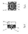
- die teilweise geschnitten dargestellte Seitenansicht der Pumpe der Vor- richtung gemäß
Fig. 1 , - Fig. 3
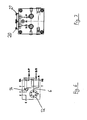
- die zu
Fig. 2 zugehörige Vorderansicht der Pumpe, - Fig. 4
- schematisch den Leitungsplan eines Zweileitungszentralschmiersystems mit zwei Umsteuerventilen, durch das das von der Vorrichtung gemäß
Fig. 1 geförderte Schmiermittel verteilt wird, - Fig. 5
- das System nach
Fig. 4 in einer vorrichtungstechnischen Umsetzung, - Fig. 6
- schematisch den Leitungsplan eines Zweileitungszentralschmiersystems ohne Umsteuerventile, durch das das von der Vorrichtung gemäß
Fig. 1 geförderte Schmiermittel verteilt wird, - Fig. 7
- das System nach
Fig. 6 in einer vorrichtungstechnischen Umsetzung, - Fig. 8
- schematisch den Leitungsplan eines Einleitungszentralschmiersystems mit einem Umsteuerventil, durch das das von der Vorrichtung gemäß
Fig. 1 geförderte Schmiermittel verteilt wird, - Fig. 9
- das System nach
Fig. 8 in einer vorrichtungstechnischen Umsetzung, - Fig. 10
- schematisch den Leitungsplan eines Zentralschmiersystems ohne Um- steuerventile, durch das das von der Vorrichtung gemäß
Fig. 1 geförderte Schmiermittel verteilt wird und - Fig. 11
- das System nach
Fig. 10 in einer vorrichtungstechnischen Umsetzung.
- Fig. 1
- 1 is a schematic side view of a lubricant supply device;
- Fig. 2
- the partially sectioned side view of the pump according to the device according to
Fig. 1 . - Fig. 3
- the too
Fig. 2 associated front view of the pump, - Fig. 4
- schematically the piping plan of a two-line centralized lubrication system with two changeover valves, by which of the device according to
Fig. 1 subsidized lubricant is distributed, - Fig. 5
- the system after
Fig. 4 in a device implementation, - Fig. 6
- schematically the line diagram of a two-line centralized lubrication system without changeover valves, by which of the device according to
Fig. 1 subsidized lubricant is distributed, - Fig. 7
- the system after
Fig. 6 in a device implementation, - Fig. 8
- schematically the piping plan of a single-line central lubrication system with a reversing valve, by which of the device according to
Fig. 1 subsidized lubricant is distributed, - Fig. 9
- the system after
Fig. 8 in a device implementation, - Fig. 10
- schematically shows the piping plan of a centralized lubrication system without reversing valves, by which of the device according to
Fig. 1 subsidized lubricant is distributed and - Fig. 11
- the system after
Fig. 10 in a device implementation.
In
Die Vorrichtung 1 hat einen Aufnahmebehälter 2 für Schmiermittel (Öl oder Fett) und ist bevorzugt zylindrisch ausgeführt; möglich ist aber auch eine eckige Grundform. Ein Motor 3 treibt die Welle 7 eines Förderelements 4 in Form einer Förderschnecke an. Ein Schneckengang 8, der als Fördermittel fungiert, erstreckt sich wendelförmig in bekannter Weise um die Welle 7 herum und fördert bei der Rotation der Welle 7 Schmiermittel. Am einen (rechten) axialen Ende der Welle 7 ist eine Pumpe 5 in Form einer Radialkolbenpumpe angeordnet. Die Pumpe 5 weist ein Wellenteil 9 auf, das mit der Welle 7 drehfest gekoppelt ist.The device 1 has a
Dabei ist die drehfeste Verbindung 16 (s.
Wie aus den
Aus den
Eine Absicherung der Schmiermittelleitung 6 gegen Überdruck erfolgt durch ein Überdruckventil 14.A protection of the
Gemäß
In
In
In
In
Der Motor 3 ist ein Getriebemotor mit insbesondere elektrischem, hydraulischem oder pneumatischem Antrieb. Die Förderschnecke 4 fördert durch die Drehung des Motors 3 Medium zur Pumpe 5 und treibt diese gleichzeitig an.The
Der Aufnahmebehälter 2 wird bevorzugt in Behältergrößen für die Aufnahme von 15, 30 oder 60 kg Schmiermittel ausgelegt.The
Der Erfindungsvorschlag zeichnet sich dadurch aus, dass die Anordnung von Motor, Förderschnecke und Pumpe modular aufgebaut ist. Diese Elemente sind bevorzugt nur formschlüssig gekoppelt, d. h. sie sind zusammengesteckt und nicht kraftschlüssig miteinander verbunden. Das erlaubt eine einfache Demontage bzw. einen einfachen Austausch von Pumpe und Motor ohne Demontage der jeweils anderen Komponenten. Durch diese modulare Bauweise kann sehr einfach nachträglich Pumpe oder Motor/Getriebe ausgetauscht werden, um andere Leistungsbereiche zu erreichen.The proposed invention is characterized in that the arrangement of motor, screw conveyor and pump is modular. These elements are preferably coupled only form-fitting, ie they are plugged together and not positively connected to each other. This allows easy disassembly or a simple exchange of pump and motor without disassembly of the other components. This modular design can be easily replaced afterwards pump or motor / gearbox to achieve other power ranges.
Durch die Wahl der Anzahl der Radialkolbeneinheiten 10 - vorzugsweise werden zwischen 1 und 6 Einheiten gewählt - kann eine gewünschte Förderleistung verwirklicht werden.By choosing the number of radial piston units 10 - preferably between 1 and 6 units selected - a desired delivery rate can be realized.
Die Pumpe 5 kann - wie oben ausgeführt - durch unterschiedliche Bestückung (1 Mal 3/2-Wege-Ventil bzw. 2 Mal 3/2-Wege-Ventil oder kein 3/2-wege-Ventil) die Ausgangsleitungen mit Druck beaufschlagen oder als Rücklaufleitung dienen.The
- 11
- SchmiermittelversorgungsvorrichtungLubricant supply device
- 22
- Aufnahmebehälterreceptacle
- 33
- Motorengine
- 44
- Förderelement (Förderschnecke)Conveying element (screw conveyor)
- 55
- Pumpe (Radialkolbenpumpe)Pump (radial piston pump)
- 66
- Schmiermittelleitunglubricant line
- 77
- Wellewave
- 88th
- Fördermittel (Schneckengang)Conveying means (worm thread)
- 99
- Wellenteilshaft part
- 1010
- RadialkolbeneinheitRadial piston unit
- 1111
- Exzentereccentric
- 1212
- Ringleitungloop
- 1313
- Rückschlagventilcheck valve
- 1414
- ÜberdruckventilPressure relief valve
- 1515
- Wegeventilway valve
- 1616
- drehfeste Verbindungnon-rotatable connection
- 1717
- Nutgroove
- 1818
- VentilValve
- 1919
- VentilValve
- 2020
- Umlenkplattebaffle
- 2121
- Umlenkplattebaffle
- 2222
- Verschlussplatteclosing plate
- 2323
- Umlenkplattebaffle
- 2424
- Verschlussplatteclosing plate
Claims (15)
Priority Applications (1)
| Application Number | Priority Date | Filing Date | Title |
|---|---|---|---|
| US12/657,349 US20100272584A1 (en) | 2008-05-15 | 2010-01-19 | Fluid supplying device |
Applications Claiming Priority (1)
| Application Number | Priority Date | Filing Date | Title |
|---|---|---|---|
| DE102008023674A DE102008023674B4 (en) | 2008-05-15 | 2008-05-15 | Lubricant supply device |
Publications (2)
| Publication Number | Publication Date |
|---|---|
| EP2119951A2 true EP2119951A2 (en) | 2009-11-18 |
| EP2119951A3 EP2119951A3 (en) | 2011-05-04 |
Family
ID=40795080
Family Applications (1)
| Application Number | Title | Priority Date | Filing Date |
|---|---|---|---|
| EP09005883A Withdrawn EP2119951A3 (en) | 2008-05-15 | 2009-04-28 | Lubricant supply device |
Country Status (3)
| Country | Link |
|---|---|
| US (1) | US20100272584A1 (en) |
| EP (1) | EP2119951A3 (en) |
| DE (1) | DE102008023674B4 (en) |
Families Citing this family (4)
| Publication number | Priority date | Publication date | Assignee | Title |
|---|---|---|---|---|
| US9388940B2 (en) | 2010-11-29 | 2016-07-12 | Lincoln Industrial Corporation | Variable speed stepper motor driving a lubrication pump system |
| US9222618B2 (en) | 2010-11-29 | 2015-12-29 | Lincoln Industrial Corporation | Stepper motor driving a lubrication pump providing uninterrupted lubricant flow |
| US8936135B2 (en) | 2010-11-29 | 2015-01-20 | Lincoln Industrial Corporation | Pump having heated reservoir |
| US9671065B2 (en) | 2013-10-17 | 2017-06-06 | Lincoln Industrial Corporation | Pump having wear and wear rate detection |
Citations (11)
| Publication number | Priority date | Publication date | Assignee | Title |
|---|---|---|---|---|
| US1898815A (en) | 1929-10-26 | 1933-02-21 | Kenneth S Clapp | Lubricator pump |
| DE617233C (en) * | 1932-04-30 | 1935-08-15 | Robert Bosch Akt Ges | Lubricator for rigid greases |
| US2561786A (en) * | 1951-07-24 | Centralized | ||
| GB864188A (en) | 1957-03-20 | 1961-03-29 | Kelsey Ind Ltd | Improvements in or relating to apparatus for distributing mastic substances |
| DE2526859A1 (en) | 1975-06-16 | 1976-12-30 | Ingbuero Junginger Gmbh & Co K | Lubrication system for machine components - has dispenser with intermediate reservoir return connection and level indicator |
| EP0009908B1 (en) | 1978-09-28 | 1983-02-02 | General Electric Company | Apparatus and method for pumping lubricant wicking material |
| US4642040A (en) | 1985-08-23 | 1987-02-10 | Normag Corporation | Extruder drivingly connected to gear pump |
| EP0642913A1 (en) | 1993-09-15 | 1995-03-15 | Bayer Ag | Single screw extruder with gear pump |
| US5634777A (en) * | 1990-06-29 | 1997-06-03 | Albertin; Marc S. | Radial piston fluid machine and/or adjustable rotor |
| EP1352729A1 (en) | 2002-04-08 | 2003-10-15 | COLMEC S.p.A. | Screw extruder with discharge pump |
| DE10348985B3 (en) | 2003-10-22 | 2005-05-19 | Berstorff Gmbh | gear pump |
Family Cites Families (4)
| Publication number | Priority date | Publication date | Assignee | Title |
|---|---|---|---|---|
| US2495671A (en) * | 1944-12-18 | 1950-01-24 | Standard Steel Works | Apparatus for dispensing viscose fluids |
| DE2242435C3 (en) * | 1972-08-29 | 1981-09-24 | Alfred Teves Gmbh, 6000 Frankfurt | Radial piston pump |
| DE3513164A1 (en) * | 1985-04-12 | 1986-10-23 | Robert Bosch Gmbh, 7000 Stuttgart | RADIAL PISTON PUMP |
| DE102006016687A1 (en) * | 2006-04-08 | 2007-10-18 | Audi Ag | Wet-sump-lubricated internal-combustion engine for use in motor vehicle, has oil pump for pumping engine oil, and screw conveyor for conveying engine oil in suction area of oil pump |
-
2008
- 2008-05-15 DE DE102008023674A patent/DE102008023674B4/en active Active
-
2009
- 2009-04-28 EP EP09005883A patent/EP2119951A3/en not_active Withdrawn
-
2010
- 2010-01-19 US US12/657,349 patent/US20100272584A1/en not_active Abandoned
Patent Citations (11)
| Publication number | Priority date | Publication date | Assignee | Title |
|---|---|---|---|---|
| US2561786A (en) * | 1951-07-24 | Centralized | ||
| US1898815A (en) | 1929-10-26 | 1933-02-21 | Kenneth S Clapp | Lubricator pump |
| DE617233C (en) * | 1932-04-30 | 1935-08-15 | Robert Bosch Akt Ges | Lubricator for rigid greases |
| GB864188A (en) | 1957-03-20 | 1961-03-29 | Kelsey Ind Ltd | Improvements in or relating to apparatus for distributing mastic substances |
| DE2526859A1 (en) | 1975-06-16 | 1976-12-30 | Ingbuero Junginger Gmbh & Co K | Lubrication system for machine components - has dispenser with intermediate reservoir return connection and level indicator |
| EP0009908B1 (en) | 1978-09-28 | 1983-02-02 | General Electric Company | Apparatus and method for pumping lubricant wicking material |
| US4642040A (en) | 1985-08-23 | 1987-02-10 | Normag Corporation | Extruder drivingly connected to gear pump |
| US5634777A (en) * | 1990-06-29 | 1997-06-03 | Albertin; Marc S. | Radial piston fluid machine and/or adjustable rotor |
| EP0642913A1 (en) | 1993-09-15 | 1995-03-15 | Bayer Ag | Single screw extruder with gear pump |
| EP1352729A1 (en) | 2002-04-08 | 2003-10-15 | COLMEC S.p.A. | Screw extruder with discharge pump |
| DE10348985B3 (en) | 2003-10-22 | 2005-05-19 | Berstorff Gmbh | gear pump |
Also Published As
| Publication number | Publication date |
|---|---|
| EP2119951A3 (en) | 2011-05-04 |
| US20100272584A1 (en) | 2010-10-28 |
| DE102008023674A1 (en) | 2009-11-26 |
| DE102008023674B4 (en) | 2012-03-22 |
Similar Documents
| Publication | Publication Date | Title |
|---|---|---|
| EP2024140B1 (en) | Automatic lubricating pump with double-acting drive piston | |
| DE102011055194B4 (en) | Hydraulic pump assembly | |
| EP3074689B1 (en) | Emergency lubrication for wind turbine gearboxes | |
| EP3098457B1 (en) | Hydrostatic linear actuator and assembly with hydrostatic linear actuators | |
| EP1210519B1 (en) | Gear pump with a drive and a hydraulic tank | |
| DE102008023674B4 (en) | Lubricant supply device | |
| EP1954972B1 (en) | Feed pump and modular pump system | |
| DE102019106681B4 (en) | lubricator | |
| DE202005019485U1 (en) | lubricant pump | |
| DE3631408A1 (en) | AXIAL PISTON PUMP | |
| WO2019030001A1 (en) | Pump unit, storage device equipped therewith, and method for operating the storage device | |
| EP2935883B1 (en) | Axial piston machine of the slant axis type | |
| DE102011084828A1 (en) | delivery unit | |
| DE102015206721A1 (en) | Swash plate machine | |
| AT3212U1 (en) | RADIAL PISTON PUMP | |
| WO2006048212A2 (en) | Pump, especially slurry pump | |
| DE102013215634A1 (en) | Swash plate machine | |
| EP3728850B1 (en) | Fluid delivery device | |
| AT519817A1 (en) | hydraulic system | |
| DE202006012999U1 (en) | Lubricant container with lockable tracking device | |
| DE102012024683A1 (en) | Pump used for conveying bentonite, has pump main portion which conveys fluid bentonite from drive module, pump module and valve module that are arranged in parallel to each other and are connected through common shaft | |
| DE4410910C2 (en) | Low pulsation piston pump | |
| DE356552C (en) | Hydraulic converter of mechanical turning work in progress with longitudinal movement | |
| EP3746637A1 (en) | Vane motor | |
| WO2012083914A2 (en) | Radial piston pump |
Legal Events
| Date | Code | Title | Description |
|---|---|---|---|
| PUAI | Public reference made under article 153(3) epc to a published international application that has entered the european phase |
Free format text: ORIGINAL CODE: 0009012 |
|
| AK | Designated contracting states |
Kind code of ref document: A2 Designated state(s): AT BE BG CH CY CZ DE DK EE ES FI FR GB GR HR HU IE IS IT LI LT LU LV MC MK MT NL NO PL PT RO SE SI SK TR |
|
| PUAL | Search report despatched |
Free format text: ORIGINAL CODE: 0009013 |
|
| AK | Designated contracting states |
Kind code of ref document: A3 Designated state(s): AT BE BG CH CY CZ DE DK EE ES FI FR GB GR HR HU IE IS IT LI LT LU LV MC MK MT NL NO PL PT RO SE SI SK TR |
|
| AX | Request for extension of the european patent |
Extension state: AL BA RS |
|
| RIC1 | Information provided on ipc code assigned before grant |
Ipc: F16N 7/16 20060101AFI20090703BHEP Ipc: F16N 13/00 20060101ALI20110331BHEP |
|
| RIC1 | Information provided on ipc code assigned before grant |
Ipc: F16N 7/16 20060101AFI20110719BHEP Ipc: F16N 13/00 20060101ALI20110719BHEP |
|
| 17P | Request for examination filed |
Effective date: 20110922 |
|
| STAA | Information on the status of an ep patent application or granted ep patent |
Free format text: STATUS: EXAMINATION IS IN PROGRESS |
|
| 17Q | First examination report despatched |
Effective date: 20170130 |
|
| STAA | Information on the status of an ep patent application or granted ep patent |
Free format text: STATUS: THE APPLICATION IS DEEMED TO BE WITHDRAWN |
|
| 18D | Application deemed to be withdrawn |
Effective date: 20170810 |