EP2119326B1 - Adjustable scanner - Google Patents
Adjustable scanner Download PDFInfo
- Publication number
- EP2119326B1 EP2119326B1 EP08728222.4A EP08728222A EP2119326B1 EP 2119326 B1 EP2119326 B1 EP 2119326B1 EP 08728222 A EP08728222 A EP 08728222A EP 2119326 B1 EP2119326 B1 EP 2119326B1
- Authority
- EP
- European Patent Office
- Prior art keywords
- detector
- axis
- gantry
- ray
- rotation
- Prior art date
- Legal status (The legal status is an assumption and is not a legal conclusion. Google has not performed a legal analysis and makes no representation as to the accuracy of the status listed.)
- Active
Links
- 238000003384 imaging method Methods 0.000 claims description 13
- 238000002591 computed tomography Methods 0.000 claims description 12
- 230000005855 radiation Effects 0.000 claims description 12
- 241000282414 Homo sapiens Species 0.000 claims description 8
- 230000000149 penetrating effect Effects 0.000 claims description 4
- 230000001815 facial effect Effects 0.000 claims description 2
- 210000003128 head Anatomy 0.000 description 25
- 238000000034 method Methods 0.000 description 9
- 238000001356 surgical procedure Methods 0.000 description 6
- 230000005484 gravity Effects 0.000 description 3
- 238000013170 computed tomography imaging Methods 0.000 description 2
- 210000004709 eyebrow Anatomy 0.000 description 2
- 210000004279 orbit Anatomy 0.000 description 2
- 230000002745 absorbent Effects 0.000 description 1
- 239000002250 absorbent Substances 0.000 description 1
- 239000011358 absorbing material Substances 0.000 description 1
- 210000003484 anatomy Anatomy 0.000 description 1
- 238000003491 array Methods 0.000 description 1
- 238000010276 construction Methods 0.000 description 1
- 238000001514 detection method Methods 0.000 description 1
- 238000003745 diagnosis Methods 0.000 description 1
- 230000004899 motility Effects 0.000 description 1
- 239000000837 restrainer Substances 0.000 description 1
- 230000000717 retained effect Effects 0.000 description 1
- 210000003625 skull Anatomy 0.000 description 1
Images


Classifications
-
- A61B6/51—
-
- H—ELECTRICITY
- H05—ELECTRIC TECHNIQUES NOT OTHERWISE PROVIDED FOR
- H05G—X-RAY TECHNIQUE
- H05G1/00—X-ray apparatus involving X-ray tubes; Circuits therefor
- H05G1/02—Constructional details
-
- A—HUMAN NECESSITIES
- A61—MEDICAL OR VETERINARY SCIENCE; HYGIENE
- A61B—DIAGNOSIS; SURGERY; IDENTIFICATION
- A61B6/00—Apparatus for radiation diagnosis, e.g. combined with radiation therapy equipment
- A61B6/42—Apparatus for radiation diagnosis, e.g. combined with radiation therapy equipment with arrangements for detecting radiation specially adapted for radiation diagnosis
- A61B6/4208—Apparatus for radiation diagnosis, e.g. combined with radiation therapy equipment with arrangements for detecting radiation specially adapted for radiation diagnosis characterised by using a particular type of detector
- A61B6/4233—Apparatus for radiation diagnosis, e.g. combined with radiation therapy equipment with arrangements for detecting radiation specially adapted for radiation diagnosis characterised by using a particular type of detector using matrix detectors
-
- A—HUMAN NECESSITIES
- A61—MEDICAL OR VETERINARY SCIENCE; HYGIENE
- A61B—DIAGNOSIS; SURGERY; IDENTIFICATION
- A61B6/00—Apparatus for radiation diagnosis, e.g. combined with radiation therapy equipment
- A61B6/44—Constructional features of apparatus for radiation diagnosis
- A61B6/4429—Constructional features of apparatus for radiation diagnosis related to the mounting of source units and detector units
- A61B6/4452—Constructional features of apparatus for radiation diagnosis related to the mounting of source units and detector units the source unit and the detector unit being able to move relative to each other
-
- A—HUMAN NECESSITIES
- A61—MEDICAL OR VETERINARY SCIENCE; HYGIENE
- A61B—DIAGNOSIS; SURGERY; IDENTIFICATION
- A61B6/00—Apparatus for radiation diagnosis, e.g. combined with radiation therapy equipment
- A61B6/50—Clinical applications
- A61B6/501—Clinical applications involving diagnosis of head, e.g. neuroimaging, craniography
Definitions
- the invention relates to the examination of objects with penetrating radiation, and especially to a scanner with a detector that can be positioned in different orientations to generate different images.
- the viewing of objects, including parts of the human anatomy, by the use of x-rays and other forms of penetrating radiation is known.
- the radiation is directed at the object from one side, and the part of the radiation that penetrates the object is detected at the opposite side.
- An image may thus be obtained in which parts of the object that are more absorbent of x-rays, typically more dense parts of the object, appear as darker shadows, for example, by detecting the x-rays electronically and generating an image using a computer.
- CT computed tomography
- a series of x-ray images of a target are taken with the direction from the source to the detector differently oriented relative to the target. From these images, a three-dimensional representation of the density of x-ray absorbing material in the target may be reconstructed.
- a tomogram which is a section in a desired plane, may be generated.
- the patient sits upright, and the x-ray source and detector are mounted on opposite ends of a gantry that rotates about a vertical axis through the middle of the patient's head.
- the detector In order to obtain sufficient data to cover the desired part of the head, which is most of the extent of the skull in the horizontal plane in CT imaging with high resolution, the detector must span a substantial distance in the circumferential direction perpendicular to the axis of rotation of the gantry, that is to say, the horizontal, direction.
- Electronic detectors currently available include flat panel arrays of charge-coupled device (CCD) or other detectors, each of which converts incoming x-rays over a defined pixel area in a defined time to an electric charge that can easily be converted to a digital intensity value for subsequent computation.
- CCD charge-coupled device
- One flat panel detector commercially available from Varian Medical Systems, Inc., of Salt Lake City, Utah that is suitable for use in dental CT units has a pixel size of 127 ⁇ m (micrometers) square, and has an overall panel size of approximately 25 cm x 20 cm.
- That panel provides an effective Field of View approximately 16 cm x 13 cm.
- the 25 cm length of the panel thus allows a Field of View with a diameter of approximately 16 cm, which is large enough to permit sufficient coverage of the imaged structures in the axial (horizontal) direction with high resolution for typical dental uses.
- JP2001145616 A1 discloses the preamble of claim 1.
- the 20 cm height of the panel allows imaging only from the bottom of the lower jaw to about the bottoms of the orbits of the eyes (about 13 cm effective height at the level of the object being viewed). That is sufficient for most dental and oral surgery applications, but for some classes of orthodontic and orthognathic surgery applications an x-ray image up to the level of the glabella, roughly the level of the eyebrows, is essential.
- Such images known as "full face" have in the past been produced by conducting two overlapping scans of 13 cm height at different levels and merging the images. Conducting two scans increases the radiation dose to the patient. Merging the images seamlessly is difficult, especially as the time taken to reposition the gantry, or the patient, between the two scans allows the patient to move.
- a method and system for dental and facial computed tomography or other imaging in which a source of x-rays or other penetrating radiation and a flat-panel detector for the radiation are mounted opposite one another on a rotatable gantry, so that the head of the patient can be positioned between the source and the detector, with the axis of rotation of the gantry passing through the patient's head.
- the detector is longer in one direction than in the perpendicular direction, generally rectangular, and is rotatable between a position in which the long axis of the detector is generally perpendicular to and a position in which the long axis is generally parallel to the axis of rotation of the gantry.
- the length of the detector panel along the long axis is sufficient for fully detailed computed CT when the long axis is perpendicular to the axis of rotation of the gantry, and for full-face CT when the long axis is parallel to the axis of rotation of the gantry.
- the "vertical” direction is defined relative to the orientation of the patent's head when the patient is standing or sitting upright. Although for ease of construction and operation this direction and the direction of the axis of rotation of the gantry are substantially aligned and substantially the same as local gravitational vertical, consideration of the geometry and mechanics of the system, and the motility and flexibility of human beings, shows that exact alignment is not necessary. In addition, some dental x-ray machines operate with the patient lying down, and the "vertical" direction of the patient's head is then more nearly horizontal relative to gravity.
- the detector panel is aligned so that with the long axis perpendicular to the gantry rotation axis (landscape orientation) the center of the panel is on the center axis of the beam of radiation from the source, which center axis intersects the axis of rotation of the gantry.
- the detector panel is mounted so that one bottom corner is in the same position in both the landscape orientation and the orientation with the long axis parallel to the gantry rotation axis (portrait orientation).
- portrait orientation the panel may extend more above the center of the beam, and less to the other side of the beam, than in the landscape orientation.
- the landscape orientation is optimized for imaging the mouth
- the portrait orientation can then be optimized for full-face imaging at the same relative position of the patient's head and the scanner gantry.
- the landscape orientation is optimized for high resolution
- the portrait orientation extending as far from the axis as the landscape orientation on one side but less far on the other side, can provide a good compromise to maintain acceptable resolution with the narrower panel.
- the disclosure also provides computer software arranged to generate 3-D tomographic and other datasets and tomographic and other images in accordance with the method of the disclosure, and computer-readable media containing such software.
- the software may be written to run on an otherwise conventional computer processing tomographic data.
- the computer software may be responsive to a signal from a switch that detects the position of the sensor panel.
- the disclosure also provides data produced by the methods and systems of the invention.
- one form of tomographic apparatus 10 comprises a scanner 12 and a computer 13 controlled by a console 16 with a display 18.
- the scanner 12 comprises a source of x-rays 14, an x-ray detector 20 including a rectangular sensor array 22, and a support 24 for an object to be imaged.
- the scanner 12 is arranged to image the head, or part of the head, of a human patient (not shown), especially the jaws and teeth.
- the support 24 may then be a seat with a rest or restrainer 26 for the head or face (not shown) of the patient.
- the x-ray source 14 and x-ray detector 20 are then mounted on a rotating carrier or gantry 28 so as to circle round the position of the patient's head, while remaining aligned with one another.
- the x-ray detector 20 then records a stream of x-ray shadowgrams of the patient's head from different angles.
- the computer 13 receives the x-ray image data from the scanner 12, and calculates a 3-dimensional spatial distribution of x-ray density.
- the imaging of the patient's head and calculation of the spatial distribution may be carried out by methods and apparatus already known in the art and, in the interests of conciseness, are not further described here.
- Suitable apparatus is available commercially, for example, the i-CAT Cone Beam 3-D Dental Imaging System from Imaging Sciences International of Hatfeld, PA.
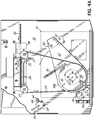
- the x-ray detector 20 comprises a panel having a rectangular array of x-ray sensitive elements, supported by a cylindrical roller bearing 30 on a mounting panel 32 attached to the gantry 28. Not shown are electrical cables and a guard that protects the cables from the moving parts. The electrical cables are partially retained between a guide 34 and the mounting panel 32.
- the x-ray source 14 is arranged to emit a beam of x-rays with an axis (the x-ray axis, not shown) that is aligned with the center of the x-ray source 14, and intersects perpendicularly the gantry axis of rotation 36 of the gantry 28 relative to the frame of the scanner 12.
- the axis 38 of the roller bearing 30 (“the detector axis") maybe parallel to but offset from the x-ray axis of source 14.
- the panel of the x-ray detector 20 is generally perpendicular to the detector axis 38, and the detector axis passes through the panel. In the embodiments shown, when the x-ray detector 20 is in the landscape orientation with the long axis of the rectangular sensor array 22 horizontal (perpendicular to the gantry axis 36), the x-ray axis is aligned with the center of the rectangular sensor array 22.
- the detector axis 38 is offset horizontally from the x-ray axis, and is positioned equal distances from the bottom, and one end of the rectangular sensor array 22.
- the panel has a rectangular sensor array 22 with an operative area 20 cm by 25 cm, and the detector axis 38 is then 10 cm from each of the bottom edge 40 and one end 42 (the left end as seen in FIG. 2 or the right end as seen in FIGS. 3 , 5A, and 5B ) of the array.
- the x-ray detector 20 is rotated 90° about the detector axis 38 from the landscape orientation seen in FIG. 5A to a portrait orientation FIG. 5B , the detector assumes a position where the bottom short edge 42 in portrait orientation is on the same line as the bottom long edge 40 in landscape orientation.
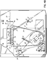
- the detector axis 38 is offset horizontally from the x-ray axis, and is positioned equal distances from the top edge 44, bottom edge 40, and one end 42 of the rectangular sensor array 22.
- the panel has a rectangular sensor array 22 with an operative area 20 cm by 25 cm, and the detector axis 38 is then 10 cm from each of the top, bottom, and one end (the left end as seen in FIG. 2 ) of the array.
- the detector 20 assumes a position (not shown) where the left-hand long edge in portrait orientation is on the same line as the left-hand short edge in landscape orientation, and the bottom long edge in portrait orientation is on the same line as the left-hand short edge in landscape orientation.
- the roller bearing 30 is a large-diameter bearing, for example, 5.5 cm diameter, with minimal play and backlash.
- a high-resolution imaging panel 20 may have a pixel size of, for example, 127 ⁇ m.
- the positioning of the x-ray detector 20 should be stable, both within a scan and between scans, to within a fraction of a pixel, say, 0.1 mm (100 ⁇ m), for high-quality imaging without extra computation.
- a very stable bearing 30 is therefore desirable.
- the x-ray detector 20 may be a commercially available flat-panel x-ray detector, such as those supplied by Varian Medical Systems, Inc., of Salt Lake City, Utah.
- a stepper motor 46 having an armature 48 (not shown) with internal threads extends and retracts an externally threaded shaft 50.
- the shaft is connected to a grab block 52 that has guides 54 that travel along two fixed rods 56 that resist the rotational forces of the motor.
- the grab block 52 is clamped to a belt 55.
- the belt passes over two pulleys 57, and around a journal 58 that is attached to the roller bearing 30.
- the motor 46 extends and retracts the shaft 50, the belt moves clockwise and counterclockwise to rotate the journal 58 and thereby the x-ray detector 20.
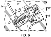
- Attached to the journal 58 is an arm 60 carrying a head 62.
- the head 62 describes an arc between two end stops 64 positioned so that the journal 58 and the arm 60 can rotate exactly ninety degrees between the end stops 64.
- the end stops 64 are provided with pins 66 for precise adjustment of the positions at which the head 62 is stopped by the end stops 64.
- the stops have hardened contact surfaces 68 and the head has hardened contact surfaces 70 ( FIG. 6 ).
- the hardened surfaces are located within counterbores 72 in the head so that both hardened surfaces are along a single plane extending from the detector axis 38.
- the non-contact end of the pins 66 rest against an adjustment screw 74 (not shown) within the end stop 64.
- the stop is split, so that tightening of a screw 76 clamps down on the pin 66.
- journal 58 is provided with actuators 78a, 78b for a pair of limit switches 80 that detect when the journal 58 is near one of its end positions.
- the limit switches signal the position to the computer 13.
- the grab block 52 comes to a stop when power to the motor is cut-off, but the arm and detector, driven by gravity, cause journal 58 to slip within the belt 54, until the contact 70 in the head 62 comes into contact with the contact 68.
- a spring 82 is pivotally connected to the mounting panel 32 and the arm 60 to carry a portion of the weight.
- the control of the position described above is just one way contemplated for low-speed contact.
- the movement of the journal 58 may be tracked in another way.
- the actuators 78a, 78b and limit switches 80 may have secondary contacts arranged to signal to the computer 13 when the head 62 is a short distance from one of the end stops 64.
- the pins 66 are set so that the end positions of the x-ray detector 20 are landscape and portrait positions with the rectangular array aligned with the gantry axis 36.
- the alignment may be precise to within a fraction of the size of a pixel over the length of the array, although the amount of precision required maybe different for different embodiments of the invention.
- the computer 13 may be programmed to rotate the journal 58, and thus the x-ray detector 20, at a moderate speed, taking several seconds for a ninety degree rotation.
- the motor 46 is braked, and the head 62 closes gently against the pin 66, so that the x-ray detector 20 is accurately positioned without an impact that might damage any part of the system.
- the scanner 12 may be used with the x-ray detector 20 in landscape orientation for a computed tomography scan of the mouth region.
- a rectangular sensor array 22 that is 25 cm wide allows the detection of x-rays sufficiently far from the axis to allow for computed tomography of a quality sufficient for almost all dental and oral surgery.
- a rectangular sensor array 22 that is 20 cm high allows most human heads to be imaged over a region extending from just below the lower jaw to about the bottom of the eye-socket. If only a region of lesser height needs to be imaged for a specific purpose, the height of the x-ray beam can be reduced by an adjustable collimator to reduce the x-ray dose to the patient.
- a collimator with four independently controllable jaws is suitable, and in some jurisdictions is required, in order to collimate the x-ray beam to the changes in the position of the detector panel.
- Such collimators are well-known in the art and, in the interests of conciseness, are not further described here.
- a rectangular sensor array 22 that is 25 cm high allows most human heads to be imaged over a region extending from just below the lower jaw to about the level of the glabella, roughly eyebrow level. The extra height is required for certain types of orthodontic and orthognathic surgery, and a 25 cm high rectangular sensor array 22 is then sufficient for about 98% of human adults.
- the positioning of the detector axis 38 relative to the x-ray detector 20 results in the bottom of the rectangular sensor array 22 of the detector panel being at the same level in both portrait and landscape orientations, so that the positioning of the patient in the scanner 12 is identical in both portrait and landscape scanning, which reduces the risk that a scan has to be repeated because the patient was incorrectly positioned.
- the positioning of the detector axis 38 relative to the x-ray detector 20 may be chosen so that one side of the rectangular sensor array 22 is the full 12.5 cm from the x-ray axis, with the other side of the array only 7.5 cm from the x-ray axis.
- the 12.5 cm extent on one side of the axis gives better coverage diametrally in computed tomography imaging than a panel extending to 10 cm on both sides of the x-ray axis, by using a known reconstruction method commonly referred to as "half beam mode.”
- half beam mode a reconstruction method commonly referred to as "half beam mode.”
- the image quality is less than with a 25 cm wide array, it has been found to be sufficient for most forms of orthodontic and orthognathic surgery.
- the 25 cm high full face scan can be combined with a second scan, using the x-ray detector 20 in 25 cm wide landscape orientation, but with the x-ray beam collimated to only 6 or 8 cm high.
- Such a double scan can be conducted with less x-ray dosage to the patient than would result from a full-face scan using two overlapping scans from a scanner with a fixed detector panel 25 cm wide by 20 cm high.
- Certain commercially available detector panels suitable for use as the x-ray detector 20 are provided with built-in electronics for a high-resolution panoramic imaging mode, in which the x-ray beam is collimated to a narrow vertical slit, and only the detector pixels in the corresponding part of the detector array are read out. That mode greatly speeds the readout process, by reducing the number of pixels read.
- the available panels support that panoramic slit mode only in landscape orientation. High resolution full-face panoramic imaging is not usually needed, but the rotatable x-ray detector 20 of the present device allows switching between operating modes including a 25 cm high full-face scan and the panoramic slit mode where a fixed detector panel, in either orientation, could offer only one of those modes.
- a detector panel with an array of sensors 20 cm by 25 cm has been used. That is only an example, and detector panels of other sizes may be used.
- a x-ray detector 20 positioned with the axis of the bearing 30 equidistant from two edges of the panel, so that the bottom edge and one side edge are at the same positions relative to the gantry in the landscape and portrait modes has been described. Also described as an example is a x-ray detector 20 positioned with the axis of the bearing 30 equidistant from three edges of the panel, so that the bottom edge and one side edge are in the same positions relative to the gantry in the landscape and portrait modes. Certain reasons for those arrangements have been identified. However, other positions of the x-ray detector 20 relative to the axis of the bearing 30 are possible, and may be desirable for certain purposes or in certain scanner configurations.
- FIG. 1 shows that the computer 13 on which the image data are processed and analyzed is connected to the scanner 12.
- a single computer 13 may both control the scanner 12 and process the data. Alternatively, part or all of the processing may be carried out on a separate computer.
- the data from the scanner 12 may be transferred from computer to computer in a convenient format, for example the DICOM format, at a convenient stage of the process.
- the data may, for example, be transferred directly from computer to computer or may, for example, be uploaded to and downloaded from a storage server.
- the detailed control of the motor 46 and the movement of the x-ray detector 20 may be controlled by a dedicated logic controller in the scanner 12, with the computer 13 or other external controller merely issuing a command to adopt a specified one of the portrait and landscape orientations, and receiving a signal confirming that the x-ray detector 20 is in a specific orientation.
Applications Claiming Priority (2)
| Application Number | Priority Date | Filing Date | Title |
|---|---|---|---|
| US89742107P | 2007-01-24 | 2007-01-24 | |
| PCT/US2008/051922 WO2008092009A2 (en) | 2007-01-24 | 2008-01-24 | Adjustable scanner |
Publications (3)
| Publication Number | Publication Date |
|---|---|
| EP2119326A2 EP2119326A2 (en) | 2009-11-18 |
| EP2119326A4 EP2119326A4 (en) | 2013-10-23 |
| EP2119326B1 true EP2119326B1 (en) | 2017-03-15 |
Family
ID=39645166
Family Applications (1)
| Application Number | Title | Priority Date | Filing Date |
|---|---|---|---|
| EP08728222.4A Active EP2119326B1 (en) | 2007-01-24 | 2008-01-24 | Adjustable scanner |
Country Status (6)
| Country | Link |
|---|---|
| US (2) | US8290119B2 (ko) |
| EP (1) | EP2119326B1 (ko) |
| KR (1) | KR101499267B1 (ko) |
| BR (1) | BRPI0807441B8 (ko) |
| DK (1) | DK2119326T3 (ko) |
| WO (1) | WO2008092009A2 (ko) |
Families Citing this family (27)
| Publication number | Priority date | Publication date | Assignee | Title |
|---|---|---|---|---|
| KR101499267B1 (ko) * | 2007-01-24 | 2015-03-05 | 이미징 사이언시즈 인터내셔널 엘엘씨 | 치과 및 안면 촬상 장치 |
| FR2924325B1 (fr) | 2007-12-03 | 2010-11-26 | Trophy | Appareil de radiologie dentaire et procede associe. |
| JP5368817B2 (ja) * | 2008-04-24 | 2013-12-18 | 浜松ホトニクス株式会社 | 医療用x線撮像システム |
| JP2010035984A (ja) * | 2008-08-08 | 2010-02-18 | Canon Inc | X線撮影装置 |
| FR2938182B1 (fr) * | 2008-08-22 | 2010-11-19 | Trophy | Appareil de radiologie dentaire et procede d'utilisation associe |
| FR2938183B1 (fr) * | 2008-08-22 | 2011-12-09 | Trophy | Appareil de radiologie dentaire panoramique et procede d'utilisation associe |
| WO2010128404A1 (en) | 2009-05-04 | 2010-11-11 | Trophy | Combined panoramic and computed tomography apparatus |
| EP2286728B1 (en) * | 2009-08-19 | 2022-03-16 | J. Morita Manufacturing Corporation | Medical x-ray apparatus |
| KR101233866B1 (ko) * | 2010-02-08 | 2013-02-15 | 고려대학교 산학협력단 | 머리 및 트랜스듀서 고정장치와 이를 포함하는 좌석 세트 |
| BR112013015849A2 (pt) * | 2010-12-22 | 2018-06-05 | Trophy | aparelho de formação de imagem, e, método para obter dados da imagem |
| FI20110106L (fi) * | 2011-03-21 | 2012-04-13 | Planmeca Oy | Hammaslääketieteellinen kuvauslaitteisto |
| US9129363B2 (en) | 2011-07-21 | 2015-09-08 | Carestream Health, Inc. | Method for teeth segmentation and alignment detection in CBCT volume |
| US8761493B2 (en) | 2011-07-21 | 2014-06-24 | Carestream Health, Inc. | Method and system for tooth segmentation in dental images |
| US8842904B2 (en) | 2011-07-21 | 2014-09-23 | Carestream Health, Inc. | Method for tooth dissection in CBCT volume |
| US8849016B2 (en) | 2011-07-21 | 2014-09-30 | Carestream Health, Inc. | Panoramic image generation from CBCT dental images |
| US8929635B2 (en) | 2011-07-21 | 2015-01-06 | Carestream Health, Inc. | Method and system for tooth segmentation in dental images |
| US9743893B2 (en) | 2011-12-21 | 2017-08-29 | Carestream Health, Inc. | Dental imaging with photon-counting detector |
| JP5944012B2 (ja) * | 2011-12-21 | 2016-07-05 | ケアストリーム ヘルス インク | 光子カウント検出器による歯科用撮像 |
| ES2935893T3 (es) * | 2012-09-07 | 2023-03-13 | Trophy | Aparato para la obtención parcial de imágenes por TC |
| US20150078513A1 (en) * | 2013-09-13 | 2015-03-19 | Seung H. Baek | Dental x-ray imaging system having higher spatial resolution |
| US10791999B2 (en) * | 2014-02-04 | 2020-10-06 | General Electric Company | Interface for gantry and component |
| FI20155005A (fi) * | 2015-01-02 | 2016-07-03 | Palodex Group Oy | Röntgenkuvantamisyksikkö lääketieteelliseen kuvantamiseen |
| US10772589B2 (en) * | 2014-09-23 | 2020-09-15 | Samsung Electronics Co., Ltd. | Receiving device and X-ray imaging apparatus having the same |
| KR102340197B1 (ko) * | 2015-02-03 | 2021-12-16 | 삼성전자주식회사 | 엑스선 장치 및 엑스선 장치의 동작 방법 |
| WO2016135526A1 (en) * | 2015-02-27 | 2016-09-01 | Trophy | Bite block for cbct imaging device |
| US10952689B2 (en) * | 2016-06-10 | 2021-03-23 | Principle Imaging Corporation | Multi-axis linear X-ray imaging system |
| EP4278975A1 (en) * | 2022-05-17 | 2023-11-22 | Koninklijke Philips N.V. | Imaging system for detecting x-ray and gamma radiation |
Family Cites Families (38)
| Publication number | Priority date | Publication date | Assignee | Title |
|---|---|---|---|---|
| JPS56137343A (en) | 1980-03-29 | 1981-10-27 | Asahi Roentgen Kogyo Kk | Obliquity photographing device of jaw |
| US5131844A (en) * | 1991-04-08 | 1992-07-21 | Foster-Miller, Inc. | Contact digitizer, particularly for dental applications |
| JP3149268B2 (ja) | 1992-04-30 | 2001-03-26 | 株式会社モリタ製作所 | 平面断層撮影機能付き曲面断層x線撮影装置 |
| US5448610A (en) * | 1993-02-09 | 1995-09-05 | Hitachi Medical Corporation | Digital X-ray photography device |
| JPH06233752A (ja) | 1993-02-09 | 1994-08-23 | Hitachi Medical Corp | ディジタルx線撮影装置 |
| JPH0724090A (ja) | 1993-07-06 | 1995-01-27 | Yamaha Corp | ゴルフ用クラブ |
| DE4405505A1 (de) | 1994-02-21 | 1995-08-31 | Siemens Ag | Computertomograph |
| JP3291406B2 (ja) * | 1995-02-09 | 2002-06-10 | 株式会社モリタ製作所 | パノラマx線撮影装置 |
| DE19533716A1 (de) * | 1995-09-12 | 1997-03-13 | Siemens Ag | Röntgendiagnostikeinrichtung mit einer Positioniervorrichtung für einen Strahlensender und einen Strahlenempfänger |
| JP3807833B2 (ja) * | 1996-12-10 | 2006-08-09 | 株式会社モリタ製作所 | X線撮影装置 |
| DE59813247D1 (de) | 1997-02-17 | 2006-01-05 | Sirona Dental Systems Gmbh | Verfahren und Einrichtung zur Erstellung von Röntgenaufnahmen von Körperteilen eines Menschen |
| JPH11318886A (ja) * | 1998-05-20 | 1999-11-24 | Asahi Roentgen Kogyo Kk | X線ct撮影をも行えるパノラマx線撮影装置 |
| US5997176A (en) * | 1998-11-11 | 1999-12-07 | Fairleigh; James F. | X-ray method and apparatus |
| CA2351534A1 (en) * | 1998-11-19 | 2000-06-02 | Direct Radiography Corporation | Apparatus and method for positioning a digital x-ray detector array |
| JP4508326B2 (ja) | 1998-11-26 | 2010-07-21 | 株式会社日立メディコ | X線透視撮影装置 |
| JP4417459B2 (ja) * | 1999-01-11 | 2010-02-17 | 株式会社東芝 | X線診断装置 |
| JP2000262502A (ja) | 1999-03-12 | 2000-09-26 | Hitachi Medical Corp | 医用x線装置 |
| DE10081367T1 (de) | 1999-04-15 | 2001-06-28 | Gen Electric | Verfahren und Gerät zur Verwendung bei einem Computertomographiesystem, das eine verkleinerte Erfassungsvorrichtung für die Abdeckung lediglich des halben Sichtfeldes verwendet |
| US6851851B2 (en) * | 1999-10-06 | 2005-02-08 | Hologic, Inc. | Digital flat panel x-ray receptor positioning in diagnostic radiology |
| JP4672099B2 (ja) * | 1999-11-22 | 2011-04-20 | 株式会社東芝 | X線診断装置 |
| DE10008053A1 (de) * | 2000-02-22 | 2001-09-06 | Siemens Ag | Röntgeneinrichtung und medizinischer Arbeitsplatz für die Diagnostik und für chirurgische Eingriffe im Kopf - und Kiefernbereich eines Patienten |
| US6666579B2 (en) * | 2000-12-28 | 2003-12-23 | Ge Medical Systems Global Technology Company, Llc | Method and apparatus for obtaining and displaying computed tomography images using a fluoroscopy imaging system |
| DE10147160C1 (de) * | 2001-09-25 | 2003-04-24 | Siemens Ag | C-Bogen-Röntgenanlage mit flexibler Detektorpositionierung |
| JP2003175027A (ja) | 2001-12-10 | 2003-06-24 | Hitachi Medical Corp | X線ct装置 |
| US7099428B2 (en) * | 2002-06-25 | 2006-08-29 | The Regents Of The University Of Michigan | High spatial resolution X-ray computed tomography (CT) system |
| CA2491759A1 (en) * | 2002-07-25 | 2004-02-19 | Gendex Corporation | Real-time digital x-ray imaging apparatus and method |
| DE60308910T2 (de) * | 2003-01-20 | 2007-10-18 | Koninklijke Philips Electronics N.V. | Medizinische bildgebungsvorrichtung mit mitteln zur gleichbehaltung der orientierung von detektor und der orientierung der wiedergabevorrichtung |
| DE10324911B4 (de) * | 2003-05-30 | 2005-08-18 | Siemens Ag | Röntgenvorrichtung mit partiellem digitalem Detektor und Verfahren zum Betrieb einer solchen |
| JP4610927B2 (ja) * | 2004-05-13 | 2011-01-12 | 富士フイルム株式会社 | 放射線乳房撮影装置 |
| DE102004050172B4 (de) | 2004-08-20 | 2010-09-02 | "Stiftung Caesar" (Center Of Advanced European Studies And Research) | 3D-Rekonstruktion mit schräger Geometrie |
| WO2006028085A1 (ja) * | 2004-09-09 | 2006-03-16 | Hitachi Medical Corporation | X線ct装置、画像処理プログラム、及び画像処理方法 |
| DE102004057004A1 (de) * | 2004-11-25 | 2006-06-01 | Siemens Ag | Röngtengerät mit rotierendem Flachdetektor |
| JP3971428B2 (ja) | 2005-03-03 | 2007-09-05 | 株式会社東芝 | X線診断装置 |
| WO2006116488A2 (en) * | 2005-04-25 | 2006-11-02 | Xoran Technologies, Inc. | Ct system with synthetic view generation |
| KR100766332B1 (ko) | 2005-08-08 | 2007-10-11 | 주식회사바텍 | 파노라마, 씨티 및 두부계측 겸용 엑스선 촬영장치 |
| JP4802079B2 (ja) | 2005-10-31 | 2011-10-26 | 株式会社モリタ製作所 | 医療用x線ct撮影装置および方法 |
| WO2008035828A1 (en) * | 2006-09-22 | 2008-03-27 | Ray Co., Ltd. | Dental complex imaging system |
| KR101499267B1 (ko) * | 2007-01-24 | 2015-03-05 | 이미징 사이언시즈 인터내셔널 엘엘씨 | 치과 및 안면 촬상 장치 |
-
2008
- 2008-01-24 KR KR1020097017425A patent/KR101499267B1/ko active IP Right Grant
- 2008-01-24 EP EP08728222.4A patent/EP2119326B1/en active Active
- 2008-01-24 US US12/524,403 patent/US8290119B2/en active Active
- 2008-01-24 BR BRPI0807441A patent/BRPI0807441B8/pt active IP Right Grant
- 2008-01-24 DK DK08728222.4T patent/DK2119326T3/en active
- 2008-01-24 WO PCT/US2008/051922 patent/WO2008092009A2/en active Application Filing
-
2012
- 2012-09-21 US US13/624,105 patent/US8934602B2/en active Active
Non-Patent Citations (1)
| Title |
|---|
| None * |
Also Published As
| Publication number | Publication date |
|---|---|
| BRPI0807441A2 (pt) | 2014-07-08 |
| US20130016806A1 (en) | 2013-01-17 |
| EP2119326A4 (en) | 2013-10-23 |
| EP2119326A2 (en) | 2009-11-18 |
| US8290119B2 (en) | 2012-10-16 |
| KR20090122213A (ko) | 2009-11-26 |
| KR101499267B1 (ko) | 2015-03-05 |
| WO2008092009A2 (en) | 2008-07-31 |
| US8934602B2 (en) | 2015-01-13 |
| DK2119326T3 (en) | 2017-05-22 |
| BRPI0807441B1 (pt) | 2020-09-29 |
| BRPI0807441B8 (pt) | 2021-06-22 |
| US20100172462A1 (en) | 2010-07-08 |
| WO2008092009A3 (en) | 2008-10-09 |
Similar Documents
| Publication | Publication Date | Title |
|---|---|---|
| EP2119326B1 (en) | Adjustable scanner | |
| JP5710274B2 (ja) | 調整可能な走査装置 | |
| JP3743594B2 (ja) | Ct撮影装置 | |
| KR101780106B1 (ko) | 파노라마 방사선 촬영, 원거리 방사선 촬영 및 선택적으로 입체 cbct 방사선 촬영을 수행하기 위한 장치 | |
| US9192342B2 (en) | Patient head support apparatus for imaging | |
| KR101766499B1 (ko) | 치과용 컴퓨터 단층 촬영 장치 | |
| JP2003290220A5 (ko) | ||
| KR20120087994A (ko) | 치과용 컴퓨터 단층 촬영 장치 | |
| CN1792330A (zh) | 快速录像的计算机x线体层照相机 | |
| JP2008532666A (ja) | 歯科用コンピュータ・トモグラフィ撮像 | |
| US9962131B2 (en) | X-ray photography apparatus, image processing device, and X-ray photography method | |
| WO2020184943A1 (ko) | 엑스선 영상촬영장치 | |
| KR102665771B1 (ko) | 엑스선 영상촬영장치 | |
| KR20190046085A (ko) | 콘 빔 컴퓨터 단층촬영장치 | |
| KR20210043390A (ko) | 엑스선 영상 촬영 장치 |
Legal Events
| Date | Code | Title | Description |
|---|---|---|---|
| PUAI | Public reference made under article 153(3) epc to a published international application that has entered the european phase |
Free format text: ORIGINAL CODE: 0009012 |
|
| 17P | Request for examination filed |
Effective date: 20090820 |
|
| AK | Designated contracting states |
Kind code of ref document: A2 Designated state(s): AT BE BG CH CY CZ DE DK EE ES FI FR GB GR HR HU IE IS IT LI LT LU LV MC MT NL NO PL PT RO SE SI SK TR |
|
| DAX | Request for extension of the european patent (deleted) | ||
| RAP1 | Party data changed (applicant data changed or rights of an application transferred) |
Owner name: DENTAL IMAGING TECHNOLOGIES CORPORATION |
|
| A4 | Supplementary search report drawn up and despatched |
Effective date: 20130923 |
|
| RIC1 | Information provided on ipc code assigned before grant |
Ipc: H05G 1/02 20060101AFI20130917BHEP Ipc: A61B 6/00 20060101ALI20130917BHEP |
|
| 17Q | First examination report despatched |
Effective date: 20140604 |
|
| REG | Reference to a national code |
Ref country code: DE Ref legal event code: R079 Ref document number: 602008049220 Country of ref document: DE Free format text: PREVIOUS MAIN CLASS: H05G0001020000 Ipc: A61B0006140000 |
|
| RIC1 | Information provided on ipc code assigned before grant |
Ipc: H05G 1/02 20060101ALI20160718BHEP Ipc: A61B 6/14 20060101AFI20160718BHEP Ipc: A61B 6/00 20060101ALI20160718BHEP |
|
| GRAP | Despatch of communication of intention to grant a patent |
Free format text: ORIGINAL CODE: EPIDOSNIGR1 |
|
| INTG | Intention to grant announced |
Effective date: 20160923 |
|
| GRAS | Grant fee paid |
Free format text: ORIGINAL CODE: EPIDOSNIGR3 |
|
| GRAA | (expected) grant |
Free format text: ORIGINAL CODE: 0009210 |
|
| AK | Designated contracting states |
Kind code of ref document: B1 Designated state(s): AT BE BG CH CY CZ DE DK EE ES FI FR GB GR HR HU IE IS IT LI LT LU LV MC MT NL NO PL PT RO SE SI SK TR |
|
| REG | Reference to a national code |
Ref country code: CH Ref legal event code: EP Ref country code: GB Ref legal event code: FG4D |
|
| REG | Reference to a national code |
Ref country code: IE Ref legal event code: FG4D |
|
| REG | Reference to a national code |
Ref country code: AT Ref legal event code: REF Ref document number: 874742 Country of ref document: AT Kind code of ref document: T Effective date: 20170415 |
|
| REG | Reference to a national code |
Ref country code: DE Ref legal event code: R096 Ref document number: 602008049220 Country of ref document: DE |
|
| REG | Reference to a national code |
Ref country code: DK Ref legal event code: T3 Effective date: 20170515 |
|
| REG | Reference to a national code |
Ref country code: NL Ref legal event code: MP Effective date: 20170315 |
|
| REG | Reference to a national code |
Ref country code: LT Ref legal event code: MG4D |
|
| PG25 | Lapsed in a contracting state [announced via postgrant information from national office to epo] |
Ref country code: LT Free format text: LAPSE BECAUSE OF FAILURE TO SUBMIT A TRANSLATION OF THE DESCRIPTION OR TO PAY THE FEE WITHIN THE PRESCRIBED TIME-LIMIT Effective date: 20170315 Ref country code: NO Free format text: LAPSE BECAUSE OF FAILURE TO SUBMIT A TRANSLATION OF THE DESCRIPTION OR TO PAY THE FEE WITHIN THE PRESCRIBED TIME-LIMIT Effective date: 20170615 Ref country code: GR Free format text: LAPSE BECAUSE OF FAILURE TO SUBMIT A TRANSLATION OF THE DESCRIPTION OR TO PAY THE FEE WITHIN THE PRESCRIBED TIME-LIMIT Effective date: 20170616 Ref country code: HR Free format text: LAPSE BECAUSE OF FAILURE TO SUBMIT A TRANSLATION OF THE DESCRIPTION OR TO PAY THE FEE WITHIN THE PRESCRIBED TIME-LIMIT Effective date: 20170315 |
|
| REG | Reference to a national code |
Ref country code: AT Ref legal event code: MK05 Ref document number: 874742 Country of ref document: AT Kind code of ref document: T Effective date: 20170315 |
|
| PG25 | Lapsed in a contracting state [announced via postgrant information from national office to epo] |
Ref country code: BG Free format text: LAPSE BECAUSE OF FAILURE TO SUBMIT A TRANSLATION OF THE DESCRIPTION OR TO PAY THE FEE WITHIN THE PRESCRIBED TIME-LIMIT Effective date: 20170615 Ref country code: LV Free format text: LAPSE BECAUSE OF FAILURE TO SUBMIT A TRANSLATION OF THE DESCRIPTION OR TO PAY THE FEE WITHIN THE PRESCRIBED TIME-LIMIT Effective date: 20170315 Ref country code: SE Free format text: LAPSE BECAUSE OF FAILURE TO SUBMIT A TRANSLATION OF THE DESCRIPTION OR TO PAY THE FEE WITHIN THE PRESCRIBED TIME-LIMIT Effective date: 20170315 |
|
| PG25 | Lapsed in a contracting state [announced via postgrant information from national office to epo] |
Ref country code: NL Free format text: LAPSE BECAUSE OF FAILURE TO SUBMIT A TRANSLATION OF THE DESCRIPTION OR TO PAY THE FEE WITHIN THE PRESCRIBED TIME-LIMIT Effective date: 20170315 |
|
| PG25 | Lapsed in a contracting state [announced via postgrant information from national office to epo] |
Ref country code: RO Free format text: LAPSE BECAUSE OF FAILURE TO SUBMIT A TRANSLATION OF THE DESCRIPTION OR TO PAY THE FEE WITHIN THE PRESCRIBED TIME-LIMIT Effective date: 20170315 Ref country code: CZ Free format text: LAPSE BECAUSE OF FAILURE TO SUBMIT A TRANSLATION OF THE DESCRIPTION OR TO PAY THE FEE WITHIN THE PRESCRIBED TIME-LIMIT Effective date: 20170315 Ref country code: EE Free format text: LAPSE BECAUSE OF FAILURE TO SUBMIT A TRANSLATION OF THE DESCRIPTION OR TO PAY THE FEE WITHIN THE PRESCRIBED TIME-LIMIT Effective date: 20170315 Ref country code: AT Free format text: LAPSE BECAUSE OF FAILURE TO SUBMIT A TRANSLATION OF THE DESCRIPTION OR TO PAY THE FEE WITHIN THE PRESCRIBED TIME-LIMIT Effective date: 20170315 Ref country code: SK Free format text: LAPSE BECAUSE OF FAILURE TO SUBMIT A TRANSLATION OF THE DESCRIPTION OR TO PAY THE FEE WITHIN THE PRESCRIBED TIME-LIMIT Effective date: 20170315 Ref country code: ES Free format text: LAPSE BECAUSE OF FAILURE TO SUBMIT A TRANSLATION OF THE DESCRIPTION OR TO PAY THE FEE WITHIN THE PRESCRIBED TIME-LIMIT Effective date: 20170315 |
|
| PG25 | Lapsed in a contracting state [announced via postgrant information from national office to epo] |
Ref country code: PL Free format text: LAPSE BECAUSE OF FAILURE TO SUBMIT A TRANSLATION OF THE DESCRIPTION OR TO PAY THE FEE WITHIN THE PRESCRIBED TIME-LIMIT Effective date: 20170315 Ref country code: IS Free format text: LAPSE BECAUSE OF FAILURE TO SUBMIT A TRANSLATION OF THE DESCRIPTION OR TO PAY THE FEE WITHIN THE PRESCRIBED TIME-LIMIT Effective date: 20170715 Ref country code: PT Free format text: LAPSE BECAUSE OF FAILURE TO SUBMIT A TRANSLATION OF THE DESCRIPTION OR TO PAY THE FEE WITHIN THE PRESCRIBED TIME-LIMIT Effective date: 20170717 |
|
| REG | Reference to a national code |
Ref country code: DE Ref legal event code: R097 Ref document number: 602008049220 Country of ref document: DE |
|
| PLBE | No opposition filed within time limit |
Free format text: ORIGINAL CODE: 0009261 |
|
| STAA | Information on the status of an ep patent application or granted ep patent |
Free format text: STATUS: NO OPPOSITION FILED WITHIN TIME LIMIT |
|
| REG | Reference to a national code |
Ref country code: FR Ref legal event code: PLFP Year of fee payment: 11 |
|
| 26N | No opposition filed |
Effective date: 20171218 |
|
| PG25 | Lapsed in a contracting state [announced via postgrant information from national office to epo] |
Ref country code: SI Free format text: LAPSE BECAUSE OF FAILURE TO SUBMIT A TRANSLATION OF THE DESCRIPTION OR TO PAY THE FEE WITHIN THE PRESCRIBED TIME-LIMIT Effective date: 20170315 |
|
| REG | Reference to a national code |
Ref country code: CH Ref legal event code: PL |
|
| GBPC | Gb: european patent ceased through non-payment of renewal fee |
Effective date: 20180124 |
|
| PG25 | Lapsed in a contracting state [announced via postgrant information from national office to epo] |
Ref country code: LU Free format text: LAPSE BECAUSE OF NON-PAYMENT OF DUE FEES Effective date: 20180124 |
|
| REG | Reference to a national code |
Ref country code: IE Ref legal event code: MM4A |
|
| REG | Reference to a national code |
Ref country code: BE Ref legal event code: MM Effective date: 20180131 |
|
| PG25 | Lapsed in a contracting state [announced via postgrant information from national office to epo] |
Ref country code: BE Free format text: LAPSE BECAUSE OF NON-PAYMENT OF DUE FEES Effective date: 20180131 Ref country code: CH Free format text: LAPSE BECAUSE OF NON-PAYMENT OF DUE FEES Effective date: 20180131 Ref country code: GB Free format text: LAPSE BECAUSE OF NON-PAYMENT OF DUE FEES Effective date: 20180124 Ref country code: LI Free format text: LAPSE BECAUSE OF NON-PAYMENT OF DUE FEES Effective date: 20180131 |
|
| PG25 | Lapsed in a contracting state [announced via postgrant information from national office to epo] |
Ref country code: IE Free format text: LAPSE BECAUSE OF NON-PAYMENT OF DUE FEES Effective date: 20180124 |
|
| PG25 | Lapsed in a contracting state [announced via postgrant information from national office to epo] |
Ref country code: MC Free format text: LAPSE BECAUSE OF FAILURE TO SUBMIT A TRANSLATION OF THE DESCRIPTION OR TO PAY THE FEE WITHIN THE PRESCRIBED TIME-LIMIT Effective date: 20170315 |
|
| PG25 | Lapsed in a contracting state [announced via postgrant information from national office to epo] |
Ref country code: MT Free format text: LAPSE BECAUSE OF NON-PAYMENT OF DUE FEES Effective date: 20180124 |
|
| PG25 | Lapsed in a contracting state [announced via postgrant information from national office to epo] |
Ref country code: TR Free format text: LAPSE BECAUSE OF FAILURE TO SUBMIT A TRANSLATION OF THE DESCRIPTION OR TO PAY THE FEE WITHIN THE PRESCRIBED TIME-LIMIT Effective date: 20170315 |
|
| PG25 | Lapsed in a contracting state [announced via postgrant information from national office to epo] |
Ref country code: HU Free format text: LAPSE BECAUSE OF FAILURE TO SUBMIT A TRANSLATION OF THE DESCRIPTION OR TO PAY THE FEE WITHIN THE PRESCRIBED TIME-LIMIT; INVALID AB INITIO Effective date: 20080124 |
|
| PG25 | Lapsed in a contracting state [announced via postgrant information from national office to epo] |
Ref country code: CY Free format text: LAPSE BECAUSE OF FAILURE TO SUBMIT A TRANSLATION OF THE DESCRIPTION OR TO PAY THE FEE WITHIN THE PRESCRIBED TIME-LIMIT Effective date: 20170315 |
|
| PGFP | Annual fee paid to national office [announced via postgrant information from national office to epo] |
Ref country code: DK Payment date: 20230111 Year of fee payment: 16 |
|
| PGFP | Annual fee paid to national office [announced via postgrant information from national office to epo] |
Ref country code: IT Payment date: 20221213 Year of fee payment: 16 |
|
| P01 | Opt-out of the competence of the unified patent court (upc) registered |
Effective date: 20230525 |
|
| REG | Reference to a national code |
Ref country code: DE Ref legal event code: R079 Ref document number: 602008049220 Country of ref document: DE Free format text: PREVIOUS MAIN CLASS: A61B0006140000 Ipc: A61B0006510000 |
|
| PGFP | Annual fee paid to national office [announced via postgrant information from national office to epo] |
Ref country code: FR Payment date: 20231212 Year of fee payment: 17 Ref country code: FI Payment date: 20231218 Year of fee payment: 17 |
|
| PGFP | Annual fee paid to national office [announced via postgrant information from national office to epo] |
Ref country code: DE Payment date: 20231205 Year of fee payment: 17 |