EP2118904B1 - Elektronische sicherungsvorrichtung und -verfahren mit adressierbare virtuelle elektronische sicherungen - Google Patents
Elektronische sicherungsvorrichtung und -verfahren mit adressierbare virtuelle elektronische sicherungen Download PDFInfo
- Publication number
- EP2118904B1 EP2118904B1 EP08707883A EP08707883A EP2118904B1 EP 2118904 B1 EP2118904 B1 EP 2118904B1 EP 08707883 A EP08707883 A EP 08707883A EP 08707883 A EP08707883 A EP 08707883A EP 2118904 B1 EP2118904 B1 EP 2118904B1
- Authority
- EP
- European Patent Office
- Prior art keywords
- fuse
- state
- vef
- blown
- virtual
- Prior art date
- Legal status (The legal status is an assumption and is not a legal conclusion. Google has not performed a legal analysis and makes no representation as to the accuracy of the status listed.)
- Active
Links
- 238000000034 method Methods 0.000 title claims abstract description 27
- 230000008859 change Effects 0.000 claims abstract description 42
- 230000001747 exhibiting effect Effects 0.000 claims abstract description 30
- 230000004044 response Effects 0.000 claims description 25
- 239000004065 semiconductor Substances 0.000 claims description 9
- 230000008569 process Effects 0.000 description 11
- 238000007664 blowing Methods 0.000 description 10
- 238000010586 diagram Methods 0.000 description 10
- 230000007704 transition Effects 0.000 description 6
- 230000007246 mechanism Effects 0.000 description 5
- 238000004519 manufacturing process Methods 0.000 description 4
- 238000001514 detection method Methods 0.000 description 3
- 230000008901 benefit Effects 0.000 description 2
- 238000012508 change request Methods 0.000 description 2
- 230000000694 effects Effects 0.000 description 2
- 238000005516 engineering process Methods 0.000 description 2
- 229910021420 polycrystalline silicon Inorganic materials 0.000 description 2
- 229920005591 polysilicon Polymers 0.000 description 2
- 238000012360 testing method Methods 0.000 description 2
- 230000009471 action Effects 0.000 description 1
- 238000013459 approach Methods 0.000 description 1
- 230000000712 assembly Effects 0.000 description 1
- 238000000429 assembly Methods 0.000 description 1
- 238000004891 communication Methods 0.000 description 1
- 239000012141 concentrate Substances 0.000 description 1
- 238000012937 correction Methods 0.000 description 1
- 230000007547 defect Effects 0.000 description 1
- 230000001419 dependent effect Effects 0.000 description 1
- 230000006870 function Effects 0.000 description 1
- 230000000873 masking effect Effects 0.000 description 1
- 238000012986 modification Methods 0.000 description 1
- 230000004048 modification Effects 0.000 description 1
- 230000002093 peripheral effect Effects 0.000 description 1
- 238000012545 processing Methods 0.000 description 1
- 230000002441 reversible effect Effects 0.000 description 1
- 238000012552 review Methods 0.000 description 1
Images


Classifications
-
- G—PHYSICS
- G11—INFORMATION STORAGE
- G11C—STATIC STORES
- G11C17/00—Read-only memories programmable only once; Semi-permanent stores, e.g. manually-replaceable information cards
- G11C17/14—Read-only memories programmable only once; Semi-permanent stores, e.g. manually-replaceable information cards in which contents are determined by selectively establishing, breaking or modifying connecting links by permanently altering the state of coupling elements, e.g. PROM
- G11C17/18—Auxiliary circuits, e.g. for writing into memory
-
- G—PHYSICS
- G11—INFORMATION STORAGE
- G11C—STATIC STORES
- G11C8/00—Arrangements for selecting an address in a digital store
- G11C8/06—Address interface arrangements, e.g. address buffers
-
- G—PHYSICS
- G11—INFORMATION STORAGE
- G11C—STATIC STORES
- G11C8/00—Arrangements for selecting an address in a digital store
- G11C8/10—Decoders
-
- G—PHYSICS
- G11—INFORMATION STORAGE
- G11C—STATIC STORES
- G11C17/00—Read-only memories programmable only once; Semi-permanent stores, e.g. manually-replaceable information cards
- G11C17/14—Read-only memories programmable only once; Semi-permanent stores, e.g. manually-replaceable information cards in which contents are determined by selectively establishing, breaking or modifying connecting links by permanently altering the state of coupling elements, e.g. PROM
- G11C17/16—Read-only memories programmable only once; Semi-permanent stores, e.g. manually-replaceable information cards in which contents are determined by selectively establishing, breaking or modifying connecting links by permanently altering the state of coupling elements, e.g. PROM using electrically-fusible links
Definitions
- the disclosures herein relate generally to electronic fuses, and more particularly, to an apparatus and methodology for programming electronic fuses in electronic devices.
- Modem electronic devices often include electronic fuses for use in final configuration after completion of semiconductor masking and fabrication processes. These electronic fuses are typically useful in the customization of electronic devices or to correct semiconductor manufacturing defects.
- an integrated circuit such as a processor may include multiple electronic fuses that store digital information. Each electronic fuse may store a logic 0 or logic 1 depending on whether the fuse exhibits an un-blown state or a blown-state.
- a programming mechanism passes a high current through a polysilicon electronic fuse to permanently change the resistance of the fuse from a low resistance of approximately 100 ohms (the un-blown state) to a high resistance of approximately 5K ohms (the blown state). This action effectively "blows the fuse".
- a "blown fuse” is an electronic fuse that exhibits high resistance after the programming mechanism passes a high current therethrough.
- An "un-blown fuse” is an electronic fuse that still exhibits a low resistance.
- the programming mechanism stores digital information in an electronic fuse bank by either blowing or not blowing individual fuses of the bank.
- An un-blown fuse that exhibits a low resistance may correspond to a logic low or 0.
- a blown fuse that exhibits a high resistance may correspond to a logic high or 1. This logic convention is reversible.
- Nonvolatile storage of digital information is often desirable.
- a processor manufacturer may store final configuration information in the fuse bank of the processor. It is possible that after manufacturing a large quantity of processors and programming the fuse banks with final configuration information, an unexpected engineering change may require that the processors include different final configuration information. Under these circumstances, with no mechanism to update the final configuration information, it is unfortunately possible that those processors that store the original final configuration information may become scrap. Clearly, designating a large quantity of expensive electronic devices as scrap is not desirable.
- a method of changing state in an electronic fuse system comprising the steps of: providing a plurality of first electronic fuses that may each exhibit a blown state or a un-blown state, each first fuse having a respective address and each first fuse having a second electronic fuse that may exhibit a un-blown state or a blown state; in each first fuse, indicating, via a detector coupled to the second fuse, one of the blown state and the un-blown state if the detector receives an odd number of input signals exhibiting a first logic state, and indicating, via the detector, the other of the blown state and the un-blown state if the detector receives an even number of logic signals exhibiting the first logic state; designating a particular first fuse for state change from the un-blown state to the blown state via a fuse programmer; and, changing the state of the second fuse in the particular first fuse from a un-blown state to a blown state in response to the fuse programmer, the second fuse in the particular first fuse providing
- an electronic fuse system comprising: a plurality of first electronic fuses that may each exhibit a blown state or a un-blown state, each first fuse having a respective address, each first fuse including: a second electronic fuse that may exhibit a un-blown state or a blown state; a detector, coupled to the second fuse, that indicates one of the blown state and the un-blown state if the detector receives an odd number of input signals exhibiting a first logic state, and indicating the other of the blown state and the un-blown state if the detector receives an even number of logic signals exhibiting the first logic state; wherein the electronic fuse system includes an input that is couplable to a fuse programmer that designates a particular first fuse for state change from the un-blown state to the blown state; the second fuse in the particular first fuse changes state from a un-blown state to a blown state in response to the fuse programmer, the second fuse in the particular first fuse providing a first input signal exhibiting the first logic state
- Fig. 1 shows a block diagram of a virtual electronic fuse (VEF) 100 that includes multiple real electronic fuses (REFs), for example real electronic fuses 101 and 102 in one embodiment.
- a real electronic fuse (REF) is a physical electronic fuse device that exhibits either an un-blown or blown state. In the un-blown state, the REF exhibits a low impedance, while in the blown-state the REF exhibits a high impedance.
- One real electronic fuse is the "eFUSE" electronic fuse from IBM Corporation. (eFUSE is a trademark of the IBM Corporation.)
- the disclosed virtual electronic fuse 100 may include several real electronic fuses such as representative real electronic fuses 101 and 102 in Fig. 1 .
- the disclosed virtual electronic fuse may change state from a "virtual un-blown state” to a "virtual blown state” and from a "virtual blown state” to a “virtual un-blown state” one or more times.
- a fuse programmer 110 couples to inputs 100A and 100B of virtual electronic fuse (VEF) 100 as shown.
- a blow circuit and a sense circuit couple to each of real electronic fuses (REFs) 101 and 102, respectively. More particularly, a blow circuit 111 couples between VEF input 100A and REF 101.
- a sense circuit 121 couples between the output of REF 101 and one input of odd/even detector 125.
- a blow circuit 112 couples between fuse programmer 110 and REF 102.
- a sense circuit 122 couples between REF 102 and the remaining input of odd/even detector 125.
- Real electronic fuse (REF) 101 cooperates with blow circuit 111 and sense circuit 121 to form fuse assembly 131.
- REF 102 cooperates with a blow circuit 112 and sense circuit 122 to form fuse assembly 132.
- VEF virtual electronic fuse
- VEF virtual blown state
- the terms "effective blown state” and "virtual blown state” are interchangeable.
- odd/even detector 125 detects that VEF 100 currently includes an odd number of blown fuses.
- detector 125 generates a virtual fuse output signal at VEF output 100C to indicate that VEF exhibits a "virtual blown state”.
- VEF virtual electronic use
- programmer 110 blows real electronic fuse (REF) 102 by sending a command signal instructing blow circuit 112 to blow REF 102.
- REF real electronic fuse
- two REFs now exhibit the blown state, namely REF 101 and REF 102.
- detector 125 detects that an even number of electronic fuses currently exhibit the blown state within virtual electronic fuse (VEF) 100. In this event, detector 125 generates a virtual fuse output signal at VEF output 100C to indicate that VEF 100 now exhibits a "virtual un-blown state”.
- VEF 100 effectively returns to the un-blown state. While in this example VEF 100's two real electronic fuses (REFs) allow the effective or virtual return of the fuse to the un-blown state one time, other embodiments of the VEF may includes a larger number of REFs to allow the return of the fuse from the blown state to the un-blown state multiple times. In other words, the VEF may change state from the virtual un-blown state, to the virtual blown state, back to the virtual un-blown state, then back to the virtual blown state, and so forth as many times as the number of REFs in the VEF will allow.
- REFs real electronic fuses
- blow circuit 111 is a conventional blow circuit.
- a blow circuit causes an electronic fuse, such as a polysilicon electronic fuse, to change state from un-blown to blown upon the application of a predetermined amount of current to the fuse.
- Blow circuit 112 is similar to blow circuit 111.
- sense circuit 121 is a conventional sense circuit.
- a sense circuit senses the un-blown or blown state of a fuse and provides an output signal indicating that state.
- Sense circuit 122 is similar to sense circuit 121.
- Odd/even detector 125 may be comparator circuit. If both of sense circuits 121 and 122 sense that electronic fuses 101 and 102 are un-blown, then sense circuits 121 and 122 provide a logic low signal to the respective inputs of odd/even detector 125. In response, detector 125 finds that the signals at its inputs are the same and generates a virtual fuse output signal at VEF output 100C that indicates that VEF 100 exhibits a "virtual un-blown state". In other words, if the number of un-blown REFs in VEF 100 is even, then the virtual fuse output signal at virtual fuse output 100C is a logic low.
- detector 125 if sense circuits 121 and 122 sense that one of REFs 101 and 102 is blown and the other is un-blown, then detector 125 generates a virtual fuse output signal that indicates that the VEF 100 exhibits a "virtual blown state". In that case, the virtual fuse output signal at virtual fuse output 100 C exhibits a logic high to indicate the "virtual blown state". Detector 125 thus acts as an interpreter that examines the blown or un-blown states of the real electronic fuses (REFs) 101 and 102 in VEF 100 and, in response, generates a virtual fuse output signal at 100C to indicate the "virtual blown state" or "virtual un-blown state" of VEF 100.
- REFs real electronic fuses
- fuse programmer 110 programmed one of REFs 101 and 102 to the blown state.
- Detector 125 detected the blown state of one of REFs 101 and 102. Detector 125 thus determines that an odd number of REFs exhibit the blown state.
- detector 125 changes the virtual fuse output signal at 100C to indicate that VEF 100 currently exhibits a "virtual blown state".
- VEF virtual electronic fuse
- programmer 110 programs the remaining real electronic fuse of real fuses 101 and 102 such that both real fuses exhibit the blown state.
- sense circuits 121 and 122 each provide a logic high signal to the respective inputs of detector 125.
- detector 125 generates a virtual fuse output signal at output 100C that indicates that virtual electronic fuse 100 now exhibits a "virtual un-blown state”.
- the "virtual un-blown state" of virtual electronic fuse 100 corresponds to an even number of electronic fuses such as REF 101 and 102 exhibiting the blown state. Zero is an even number.
- virtual electronic fuse 100 exhibits a "virtual un-blown state".
- Fuse programmer 110 and virtual electronic fuse 100 together form a virtual fuse apparatus 150.
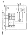
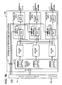
- FIG. 2 is a block diagram of another virtual electronic fuse (VEF) 200.
- VEF 100 of Figure 1 is capable of exhibiting a "virtual blown state" and returning one time to a "virtual un-blown state”
- VEF 200 and Fig. 2 is capable of several of these blown to un-blown state transitions and un-blown to blown transitions.
- Increasing the number of real electronic fuses within VEF 200 makes this improved performance possible.
- VEF 200 may cycle from the virtual un-blown state to the virtual blown state, back to the virtual un-blown state and then again to the virtual blown state as many times as the number of REFs in VEF 200 will permit.
- Virtual electronic fuse (VEF) 200 includes real electronic fuses REF(0), REF(1), ... REF(N) wherein N is the total number of real electronic fuses.
- VEF 200 also includes blow circuits BC(0), BC (1), ... BC (N) that couple to respective inputs of real electronic fuses REF(0), REF(1), ... REF(N), as shown in Figure 2 .
- VEF 200 further includes sense circuits SC(0), SC(1), ... SC(N) that couple to respective outputs of electronic fuses REF(0), REF(1), ... REF(N), as shown.
- real electronic fuse REF(0) couples to blow circuit BC(0) and sense circuit SC(0) to form an electronic fuse assembly.
- the remaining electronic fuses REF(1) ... REF(N) couple to respective blow circuits and sense circuits for form fuse assemblies within VEF 200.
- FIG. 2 shows a fuse programmer 205 that includes a number of outputs equal to the number of real electronic fuses (REFs), namely N. More particularly, fuse programmer 205 includes outputs FP(0), FP, (1), ... FP(N) that couple to respective blow circuits BC(0), BC (1), ... BC (N) of VEF 200. In this manner, fuse programmer 200 may selectively instruct any of blow circuits BC(0), BC (1), ... BC (N) to blow the respective real electronic fuse REF(0), REF(1), ... REF(N) that couples to that blow circuit.
- VEF 200 also includes a sense information bus 210 that couples each of sense circuits SC(0), SC(1), ... SC(N) to detector 215 and actual fuse register 220. In this manner, sense information bus 210 supplies detector 215 and actual fuse register 220 with sense information that indicates the number of real electronic fuses (REFs) currently exhibiting the blown state within VEF 200.
- Detector 215 interprets the sense information from sense circuits SC(0), SC(1), ... SC(N) and generates a virtual fuse output signal at output 225 that indicates whether VEF 200 currently exhibits a "virtual blown state" or a "virtual un-blown state".
- Detector 215 may be an odd/even detector. In that case, detector 215 generates a logic low output signal when detector 215 determines that an even number (0, 2, 4, ...) of real electronic fuses REF(0), REF(1), ... REF(N) exhibit a real un-blown state. This logic low output signal at VEF output 225 indicates that VEF 200 exhibits the "virtual un-blown state".
- detector 215 generates a logic high output signal when detector 215 determines than an odd number (1, 3, 5, ...) of real electronic fuses REF(0), REF(1), ... REF(N) exhibit the real blown state.
- This logic high output signal at VEF output 225 indicates that VEF 200 exhibits the "virtual blown state".
- the total number of transitions possible from the virtual un-blown state to the virtual blown state or the virtual blown state to the virtual un-blown state equals N wherein N>1 in this particular embodiment.
- Actual fuse register 220 contains a number of bit locations equal to the number of real electronic fuses REF(0), REF(1), ... REF(N) in VEF 200.
- Each bit of actual fuse register 225 corresponds to a respective real electronic fuse (REF) and indicates the state of that REF. For example, if real electronic fuse REF(0) exhibits the "blown state”, then bit 0 of register 220 exhibit a logic high. If real electronic fuse REF(3) exhibits the "un-blown state”, then bit 3 of register 20 exhibits a logic low.
- Actual fuse register 220 thus provides a path to the sensed states or values of the individual real electronic fuses (REFs) of VEF 200. This feature is useful for system software or logic (not shown) to determine the current states of individual real electronic fuses REF(0), REF(1), ... REF(N). Fuse programmer 205 and virtual electronic fuse 200 together form a virtual fuse system 250.
- Figure 3 is a state table that depicts the actual state of representative real electronic fuses REF(0), REF(1), ... REF(N) while fuse programmer 205 conducts blow and un-blow operations on selected real electronic fuses (REFs) of VEF 200.
- Figure 3 also shows the virtual output state of VEF 200.
- Figure 3 includes columns that depict the states of fuses REF(0), REF(1), ... REF(N).
- Figure 3 also includes column 305, 310 and 315 that depict the states of various components of VEF 200. For example, column 305 depicts the state of detector 215 as odd or even. In one embodiment, to make this determination, detector 215 counts the number of real electronic fuses (REFs) in VEF 200 that exhibit a logic high or blown state.
- REFs real electronic fuses
- detector 215 determines that 0, 2, 4, 6... REFs exhibit a logic high, then detector 215 interprets this as "even” and generates a logic low or zero at virtual electronic fuse (VEF) output 225.
- detector 215 determines that 1, 3, 5, ... REFs exhibit a logic high or blown state, then detector 215 interprets this as "odd” and generates a logic high at virtual fuse output 225. This logic high at output 225 indicates that VEF 200 exhibits a "virtual blown state”.
- Scenario 321 depicts the initial state of virtual electronic fuse (VEF) 200 wherein all real electronic fuses REF(0), REF(1), ... REF(N) exhibit the un-blown state, namely a logic zero in this particular example.
- Detector 215 determines that zero (an even number) real fuses exhibit a blown state, as column 305 indicates for scenario 321.
- detector 215 generates a logic low or logic zero VEF output signal at output 225, as column 310 indicates. This corresponds to an initial "virtual un-blown state", as shown in column 315 for scenario 321.
- VEF 200 To change VEF 200 from the initial "virtual un-blown state” to a "virtual blown state” in scenario 322, programmer 205 instructs blow circuit BC(0) to blow real electronic fuse REF(0). REF(0) then exhibits a logic high or one as shown in scenario 322 of Figure 3 . The remaining real electronic fuses REF(1) .... REF(N) still exhibit a logic low or zero.
- detector 305 determines that VEF 200 exhibits one blown fuse in scenario 322, namely an "odd" number of blown fuses, as seen in column 305.
- detector 215 generates a logic high or one for the virtual fuse output signal at 225, as column 310 indicates. This corresponds to VEF 200 exhibiting a "virtual blown state", as seen in column 315 for scenario 322.
- VEF 200 to return to a "virtual un-blown state".
- fuse programmer 205 instructs blow circuit BC(1) to blow real electronic fuse REF(1), as shown in scenario 323.
- Real fuse REF(1) thus exhibits a logic high or one and real fuse REF(0) also still exhibits a logic high or one because programmer 205 blew it previously.
- detector 305 determines that VEF 200 exhibits two blown real electronic fuses in scenario 323, namely an "even" number of blown REFs, as seen in column 305.
- detector 215 generates a logic low or zero for the virtual fuse output signal at 225, as column 310 indicates. This corresponds to VEF 200 once again exhibiting a "virtual un-blown state", as seen in column 315 for scenario 323.
- VEF 200 thus effectively returns to an un-blown state, namely a "virtual un-blown state” in scenario 323.
- VEF 200 is now in a "virtual un-blown state", it is possible to yet again blow VEF 200.
- fuse programmer 205 instructs blow circuit BC(2) to blow real electronic fuse REF(2), as shown in scenario 324 in Figure 3 .
- Real electronic fuse REF(2) thus exhibits a logic high and real electronic fuses REF(0) and REF(1) still exhibit logic highs because programmer 205 blew them previously.
- detector 305 determines that VEF 200 exhibits three blown REFs in scenario 324, namely an "odd" number of blown REFs, as seen in column 305.
- detector 215 generates a logic high or one for the virtual fuse output signal at 225, as column 310 indicates.
- VEF 200 again exhibiting a "virtual blown state", as seen in column 315 for scenario 324.
- VEF 200 thus returns to an un-blown state, namely a "virtual un-blown state” in scenario 324.
- Programmer 205 can continue effectively blowing and un-blowing VEF 200 until all real fuses in VEF 200 exhibit the blown state.
- the information that VEF 200 stores, or an array of such virtual fuses stores, is changeable for a number of times dependent on the number of real electronic fuses (REFs) that such VEFs contain.
- REFs real electronic fuses
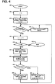
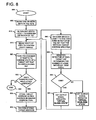
- Fig. 4 is a flowchart that depicts the methodology that a representative VEF 200 employs to change its state from "virtual un-blown” to "virtual blown” and vice versa.
- Process flow commences at start block 400.
- Index i corresponds to the number of currently blown real electronic fuses REF(0), REF(1), ... REF(N) in VEF 200.
- REFs real electronic fuses
- index i initially equals 0.
- Decision block 415 tests to determine if a user, circuit or other entity instructs or commands programmer 205 to change the virtual state of VEF 200.
- fuse programmer 205 waits for such a change state instruction, as per block 420.
- index i increments by 1, as per block 425. If index i exceeds the total number of fuses N in VEF 200 at decision block 430, then no real electronic fuses remain for state change and the process halts at end block 435. However, if index i does not exceed the total number of fuses N at decision block 430, then a blow circuit blows the current real electronic fuse, namely fuse REF(i) or REF(1) for the first time VEF 200 blows one of its real electronic fuses (REFs), as per block 440.
- REFs real electronic fuses
- Detector 215 detects the number of real fuses currently exhibiting the blown state in VEF 200, as per block 445.
- the number of REFs currently blown in VEF 200 corresponds to the current index value, i.
- decision block 450 conducts a test to determine if the number of REFs currently blown is odd or even. If the number of REFs currently blown in VEF 200 is "odd”, then detector 225 sets the state of the VEF output signal to a "virtual blown state", as per block 460. However, if the number of fuses currently blown is "even”, then detector 225 sets the state of the VEF output signal to a "virtual un-blown state", as per block 455.
- process flow continues back to decision block 415 and fuse programmer 205 again waits at block 420 for another instruction to change the state of VEF 200.
- the number of fuses currently blown equals one
- the number of blown real fuses is "odd”.
- detector 215 sets the virtual fuse output signal to exhibit a "virtual blown state”.
- change of state decision block 415 When change of state decision block 415 receives another instruction to change the state of VEF 200, i.e. now to virtually "un-blow” VEF 200, the index i increments to a value of 2. VEF 200 then blows real fuse REF(2) that corresponds to the index value 2. Because the number of REFs blown in VEF 200 is now "even", block 455 now sets the VEF output signal to the "virtual un-blown state".
- VEF 200 It is possible to yet again alter the state of VEF 200 back to the "virtual blown state". And after that it is again possible to alter the state of the VEF 200 back to the "virtual un-blown” state as long as the number of state changes or transitions does not exceed N, the number of real electronic fuses (REFs) in VEF 200.
- transition and “state change” refer to changing from the "virtual un-blown state” to the "virtual blown state” and vice versa.
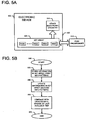
- Fig. 5A is a block diagram of an electronic device 500 that includes a virtual electronic fuse (VEF) array 505 that stores information.
- VEF array 505 includes a number of virtual electronics fuses 200.
- VEF array 505 includes VEFs 200(0), 200(1), ... 200(K) wherein K is the total number of VEFs in VEF array 500.
- Each VEF of VEF array 505 stores a bit of digital information.
- VEF array 505 may store a 16 bit word.
- each of the virtual electronic fuses in VEF array 500 is the same VEF 200 shown in Fig. 2 .
- Each of VEFs 200 in VEF array 505 may include any number of REFs greater than 1 depending on the number of updates or virtual state changes desired for these VEFs.
- each of the VEFs in VEF array 505 includes the same number of real electronic fuses (REFs), so that each VEF is updatable the same number of times as another VEF in the array.
- an electronic device includes a primary configuration of virtual electronic fuses and a manufacturer, vendor or other entity changes the configuration during manufacture of a product that includes the electronic device.
- Electronic device 500 not only includes VEF array 505, but also includes other electronic circuitry 515.
- electronic device 500 may include other electronic circuitry such as general purpose processor circuitry, special purpose processor circuitry, heterogeneous processor circuitry, digital signal processor (DSP) circuitry, logic circuitry, memory circuitry, digital circuitry, analog circuitry, mixed signal circuitry, and any other circuitry that may benefit from information storage by VEF array 505.
- DSP digital signal processor
- VEF array 505 couples to the electronic circuitry 515 to provide electronic circuitry 515 with the information that VEF array 505 stores.
- electronic device 500 constitutes a processor.
- electronic device 500 is a semiconductor device that includes a semiconductor die 520.
- Semiconductor die 520 includes VEF array 505 and electronic circuitry 515 that together form an integrated circuit.
- Fig. 5B is a flow chart that depicts a method of operating electronic device 500.
- Process flow commences at start block 550.
- Fuse programmer 510 then stores digital information in VEF array 505 by blowing selected real electronic fuses (REFs) in each of the VEFs thereof, as per block 555.
- VEF array 505 may store an 8 bit word.
- fuse programmer 510 sends a command to VEF array 505 that blows an REF in each of VEFs 200(0), 200(1), 200(2) and 200(3) while blowing no REFs in VEFs 200(4), 200(5), 200(6) and 200(7).
- VEFs 200(0), 200(1), 200(2) and 200(3) now exhibit the "virtual blown state" while the remaining VEFs exhibit the "virtual un-blown state".
- VEF array 505 it is possible to update or change the information in VEF array 505.
- 00001111 is the 8 bit word that VEF array 505 currently stores
- fuse programmer 510 instructs VEF array 505 to blow a second REF in each of VEFs 200(0) and 200(1), as per block 560.
- Fuse programmer 510 makes no changes to the remaining bits of VEF array 505, namely VEFs 200(2), 200(3), 200(4), 200(5), 200(6) and 200(7). In this manner, VEF array 505 now stores the 8 bit word 00001100.
- VEFs 200(0) and 200(1) now exhibit the "virtual un-blown state” while VEFs 200(2) and 200(3) exhibit the "virtual blown state”.
- Remaining VEFs 200(4), 200(5), 200(6) and 200(7) also exhibit the "virtual un-blown state” because fuse programmer 510 did not yet program or blow these VEFs.
- Fuse programmer 510 may perform additional updates, as per block 565, until programmer 510 blows the last available REF in one of VEFs 200(0) ... VEF 200(7). Process flow ends at end block 570.
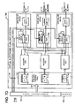
- Fig. 6 is a block diagram of an information handling system (IHS) 600 that includes an electronic device 500 that functions as the processor for IHS 600.
- electronic device 500 includes processor electronic circuitry 515 and a VEF array 505 for storing configuration information, customization information or other digital information.
- Electronic device 500 is thus a processor electronic device in this particular example.
- a fuse programmer 510 couples to processor electronic device 500 to program or update VEF array 505 at desired times with desired information.
- Processor electronic device 500 couples to memory system 610 via a bus 615 and a memory controller 620.
- Bus 615 also couples processor electronic device 500 to a video graphics controller 625.
- a display 630 couples to video graphics controller 625.
- Nonvolatile storage 635 such as a hard disk drive, CD drive, DVD drive, or other nonvolatile storage couples to bus 615 to provide IHS 600 with permanent storage of information.
- An operating system 640 loads in memory 610 to govern the operation of IHS 600.
- I/O devices 645 such as a keyboard and a mouse pointing device, couple to bus 615.
- One or more expansion busses 650 such as USB, IEEE 1394 bus, ATA, SATA, PCI, PCIE and other busses, couple to bus 615 to facilitate the connection of peripherals and devices to IHS 600.
- a network adapter 655 couples to bus 615 to enable IHS 600 to connect by wire or wirelessly to a network and other information handling systems.
- System memory 610 stores application software 660 for execution. While Fig. 6 shows one IHS that employs a processor electronic device 500 with VEF array 505, the IHS may take many forms.
- IHS 600 may take the form of a desktop, server, portable, laptop, notebook, or other form factor computer or data processing system.
- IHS 600 may take other form factors such as a personal digital assistant (PDA), a gaming device, a portable telephone device, a communication device or other devices that include a processor and memory.
- PDA personal digital assistant
- the VEF may consume a relatively high number of real fuses.
- the VEF includes 2 REFs.
- the VEF includes 11 REFs.
- An array of 10 VEFs of which each VEF is capable of 10 virtual state transitions may require 100 REFs. A more efficient way of providing virtual electronic fuse capability is desirable.
- Fig. 7A shows an example of a virtual electronic fuse (VEF) system 700 embodying the present invention that includes multiple virtual electronic fuses (VEFs) that couple to a fuse programmer 705.
- virtual electronic fuse system 700 includes 3 virtual electronic fuses, VEF(1), VEF(2) and VEF(3) although other systems may employ more virtual electronic fuses by using the teachings herein.
- Virtual EF and VEF are abbreviations for a virtual electronic fuse.
- Real EF and REF are abbreviations for a real electronic fuse.
- VEF(1) includes a real electronic fuse, REF(1), that couples to fuse programmer 705 via real fuse programming bus 707 so that fuse programmer 705 may program or blow REF(1).
- REF (1) includes an integral blow circuit (not shown) to enable the blowing of REF(1).
- REF(1) also includes an integral sense circuit (not shown) to enable the sensing of the state of REF(1).
- REF(2) and REF(3) likewise include respective blow circuits and sense circuits (not shown).
- Fuse programmer 705 includes a sense circuit 705A that senses the state of VEF(1), VEF(2) and VEF(3) after each blow or un-blow operation to confirm the success of such operation.
- Virtual electronic fuse system 700 and fuse programmer 705 together form a virtual electronic fuse apparatus 710.
- An odd/even detector circuit, OE(1) couples to REF(1). In a manner similar to that discussed above with respect to odd/even detector 125 of Fig. 1 , odd/even detector OE(1) toggles its output from a logic low to a logic high when it detects an odd number of high input signals. When odd/even detector OE(1) detects an even number of high input signals, the output of OE(1) exhibits a logic low.
- the output of odd/even detector OE(1) couples to the input of a latch L(1) that latches the logic state of the odd/even detector OE(1).
- Latch L(1) provides the output signal VEFO(1) of virtual electronic fuse VEF(1) at output 711.
- VEF(2) and VEF(3) employ the same circuit topology as VEF(1) as shown in Fig. 7A .
- VEF(2) includes real electronic fuse REF(2), odd/even detector OE(2) and latch L(2).
- Latch L(2) provides the output signal VEFO(2) of virtual electronic fuse VEF(2) at output 712.
- VEF(3) includes real electronic fuse REF(3), odd/even detector OE(3) and latch L(3).
- Latch L(3) provides the output signal VEFO(3) of virtual electronic fuse VEF(3) at output 713.
- VEF system 700 also includes an address pool 715 of real electronic fuses (REFs).
- address pool 715 includes 3 address storage locations, namely ADDRESS(1), ADDRESS(2) and ADDRESS(3).
- Address storage locations ADDRESS(1), ADDRESS(2) and ADDRESS(3) couple to respective address decoders D(1), D(2) and D(3) as shown.
- fuse programmer 705 writes the address of the particular VEF to an available one of address locations ADDRESS(1), ADDRESS(2) and ADDRESS(3), as explained in more detail below.
- address pool 715 is a shared pool of multi-bit storage locations, each bit corresponding to a real electronic fuse (REF).
- REF real electronic fuse
- Each of address decoders D(1), D(2) and D(3) includes a number of outputs equal to the number of virtual electronic fuses in VEF system 700.
- each address decoder includes 3 outputs, namely one output for each of virtual electronic fuses VEF(1), VEF(2) and VEF(3).
- address decoder D(1) includes three outputs that respectfully couple to virtual electronic fuses VEF(1), VEF(2) and VEF(3). More particularly, the 3 outputs of decoder D(1) couple to an input of the odd/even decoder OE(1) of VEF(1), an input of odd/even detector OE(2) of VEF(2) and an input of odd/even detector OE(3) of VEF(3).
- the 3 outputs of decoder D(2) couple to an input of the odd/even decoder OE(1) of VEF(1), an input of odd/even detector OE(2) of VEF(2) and an input of odd/even detector OE(3) of VEF(3).
- the 3 outputs of decoder D(3) couple to an input of the odd/even decoder OE(1) of VEF(1), an input of odd/even detector OE(2) of VEF(2) and an input of odd/even detector OE(3) of VEF(3).
- Each decoder may thus communicate with each of odd/even circuits OE(1) - OE(3) in the respective virtual electronic fuses VEF(1) - VEF(3).
- address storage locations ADDRESS(1), ADDRESS(2) and ADDRESS(3) each include 2 real electronic fuses, namely 2 bits, thus permitting 3 state changes, or blow/un-blow operations, among VEF(1), VEF(2) and VEF(3) as explained in more detail below.
- address location ADDRESS(1) includes real electronic fuses 721, 722.
- Address location ADDRESS(2) includes real electronic fuses 723, 724.
- Address location ADDRESS(3) includes real electronic fuses 725, 726.
- the designer may provide address pool 715 with address locations each exhibiting a larger number of real electronics fuses or bits to provide virtual electronic fuses VEF(1) - VEF(3) with more state changes or blow/un-blow operations.
- Increasing the bit width or size of the address pool locations allows more VEFs in VEF system 700 since each VEF of VEF system 700 consumes a respective address.
- Increasing the bit width or size of the address pool locations may also permit more virtual state changes to the VEFs.
- Fuse programmer 705 couples to real electronic fuse (REF) address pool 715 via a virtual fuse programming bus 730 so that fuse programmer 705 may select a particular one of VEF(1) - VEF(3) for virtual state change after the initial blowing of the REF of a particular VEF.
- Fuse programmer 705 sends an instruction, command, or other signal to REF address pool 715 to effect such selection of a particular VEF for state change as explained below.
- fuse programmer 705 couples to real electronic fuses REF(1) - REF(3) within virtual electronic fuses VEF(1) - VEF(3) to enable fuse programmer 705 to physically change the state of those real electronic fuses REF(1) - REF(3) to blown one time.
- These are "real blow” operations because the states of REF(1) - REF(3) themselves may change from “real un-blown” to "real blown”.
- Changing the state of any of REF(1) - REF(3) in the VEFs occurs in an initial real blow operation by programmer 705 before any following virtual state change requests or instructions by programmer 705.
- Other terms for these virtual state change requests include command signals, command instructions or programming instructions.
- Fig. 7A depicts real electronic fuses REF(1) - REF(3) of the VEFs and real electronic fuses 721 - 726 of the address pool 715 before fuse programmer 705 blows or changes the state of any of those fuses.
- Fig. 7B shows virtual electronic fuse system 700 after fuse programmer 710 conducts a real blow operation on at least one of real electronic fuses REF(1) - REF(3) of virtual electronic fuses VEF(1) - VEF(3).
- fuse programmer 705 conducts a real blow operation on real electronic fuses REF(1) and REF(2).
- fuse programmer 705 sends programming instructions, commands or other signals over programming bus 707 to REF(1) and REF(2) to cause the blowing of REF(1) and REF(2).
- the outputs of REF(1) and REF(2) go high when fuse programmer 705 blows those REFs.
- odd/even detector OE(1) detects that one of its inputs exhibits a logic high or logic 1, namely the input that couples to blown REF(1). Since this detection of a single input high is "odd", OE(1) outputs a logic high that latch L(1) latches. Thus, latch L(1) exhibits a logic high or 1 and the output VEFO(1) of virtual fuse VEF(1) exhibits a logic high as well.
- odd/even detector OE(2) detects that one of its inputs exhibits a logic high or logic 1, namely the input that couples to blown REF(2). Since this detection of a single input high is "odd", OE(2) outputs a logic high that latch L(2) latches.
- latch L(2) exhibits a logic high or 1 and the output VEFO(2) of virtual fuse VEF(2) exhibits a logic high as well.
- VEF(1) and VEF(2) now exhibit a "virtual blown state”.
- Virtual electronic fuse VEF(3) is still un-blown and thus output VEFO(3) exhibits the un-blown state, namely a logic low or 0.
- Fig. 7C shows the performance of a "virtual un-blow" state change on VEF(2).
- VEF(1) exhibits an address of 01
- VEF(2) exhibits an address of"10
- VEF(3) exhibits an address of "11”.
- Each of address locations ADDRESS(1) - ADDRESS(3) are mappable to point to one of VEF(1) - VEF(3).
- the address locations may thus act as pointers to particular VEFs depending on the particular addresses stored in the address locations.
- fuse programmer 705 may place a pointer "10" in a free or open address location in address pool 715, such as open address location ADDRESS(1).
- fuse programmer 705 places a "1" in real electronic fuse 721 by blowing REF 721.
- Fuse programmer 705 places a "0" in REF 722 by leaving REF 722 un-blown.
- fuse programmer 705 populates address location ADDRESS(1) with a "10”, namely the address of VEF(2).
- the "10" in address location ADDRESS(1) acts as an address pointer to VEF(2).
- Fuse programmer 705 accomplishes this population of the address locations in address pool 715 by sending programming instructions, commands or other signals over bus 730 to effect such population.
- Fig. 7D shows how it is possible to change the state of virtual electronic fuse VEF(2) from the "virtual un-blown state” back to the "virtual blown state”.
- fuse programmer 705 programs a remaining address location in address pool 715 to exhibit the value "10" that corresponds to the address of virtual electronic fuse VEF(2).
- fuse programmer 705 may program address location ADDRESS(2) to exhibit the "10" address that corresponds to VEF(2).
- decoder D(2) raises an input of odd/even detector OE(2) to a logic high or 1.
- 3 inputs of odd/even detector OE(2) now exhibit a logic high.
- Odd/even detector OE(2) interprets the 3 high inputs as "odd” and in response outputs a logic high to latch L(2).
- VEF0(2) exhibits such a logic high or 1
- Decoder D(3) raises an input of odd/even detector OE(1) to a logic high or 1.
- two inputs of odd/even detector OE(1) now exhibit a logic 1.
- Odd/even detector OE(1) interprets these 2 high inputs as "even” and in response outputs a logic low to latch L(1).
- VEF0(1) exhibits such a logic low, this indicates that virtual electronic fuse VEF(1) now exhibits the "virtual un-blown state" once again.
- real electronic fuse REF(3) still exhibits the real un-blown state.
- fuse programmer 705 may still at any time program or blow real electronic fuse REF(3) via real fuse programming bus 707.
- real electronic fuse REF(3) of virtual electronic fuse VEF(3) will exhibit the real blown state and the output of VEFO(3) changes to a logic high to indicate a blown fuse for VEF(3).
- all three of the 2 bit address locations in address pool 715 store address information. Thus, there is no more room in address pool 715 to accommodate further changes in the virtual states of VEF(1) - VEF(3).
- the address pool 715 may employ more address pool locations and respective decoders than shown in this particular example.
- VEF(1) - VEF(3) share the address locations of address pool 715 with respect to the number of virtual state changes possible for the VEFs. Sharing 3 address locations among the VEFs allows 3 virtual state changes total among the VEFs. Sharing 7 address locations allows 7 state changes total among the VEFs. Sharing 15 address locations allows 15 state changes among the VEFs. Increasing the bit width of each address location of address pool 715 is one way to increase the number of address locations in address pool 715. This approach allows an increase in the number of VEFs in the VEF system and an increase in the number of virtual state changes possible among the VEFs via shared address pool 715.
- Fig. 8 is a flowchart that depicts process flow for the virtual electronic fuse system 700 embodying the present invention that Figures 7A - 7E illustrate.
- Process flow commences at start block 800.
- Fuse programmer 705 then blows one or more of the real electronic fuses, REF(1) - REF(3), in virtual electronic fuses, VEF(1) - VEF(3), as per block 805.
- This is a real blow operation because the state of a real electronic changes to the blown state.
- Each blown REF then sends a logic 1 to its respective odd/even detector circuit, as per block 810. For example, if fuse programmer 805 blows REF(2), then REF (2) sends a logic 1 to odd/even detector OE (2).
- VEF(2) shows virtual electronic fuse VEF(2) wherein its real electronic fuse REF(2) exhibits the blown state and VEF(2) exhibits the "virtual blown state".
- Fuse programmer 705 may also blow more REFs within the VEFs.
- Sense circuit 705A then senses the state of the virtual electronic fuses VEF(1) - VEF(2) to confirm the success of these real blow operations, as per block 815.
- Sense circuit 705A may also sense the state of the real electronic fuses in REF address pool 715 as discussed below.
- fuse programmer 705 With one or more real electronic fuses (REFs) thus blown, fuse programmer 705 now attempts to change the state of a particular target virtual electronic fuse (VEF) that already exhibits a blown REF, as per block 820. For example, fuse programmer 705 attempts to change the state of VEF(2) from the "virtual blown state” that Fig 7B shows to the "virtual un-blown state” that Fig. 7C shows. In the blown state, the VEF(2) output signal VEFO(2) exhibits a logic 1 or high. In other words, fuse programmer 705 will attempt an un-blow operation on VEF(2). This is a "virtual un-blow" operation.
- VEF virtual electronic fuse
- Fuse programmer 705 sends a command to real electronic fuse address pool 715 to determine if any address locations are free and available. More particularly, sense circuit 705A of fuse programmer 705 senses the state of the REFs forming ADDRESS(1), ADDRESS(2) and ADDRESS(3) to determine the availability of these addresses for virtual un-blow or virtual blow operations. If no address pool location is available, then the process terminates at end block 830. However, Figure 7B shows that all three address pool locations ADDRESS(1), ADDRESS(2) and ADDRESS(3) are available in this particular example. Thus, process flow continues to block 835 wherein address pool 715 stores the target address of the target VEF in a free address location in shared address pool 715.
- fuse programmer 705 writes the address of VEF(2), namely "10", in address location ADDRESS(1) as shown in Fig. 7C .
- Decoders D(1) - D(3) decode any target address in their respective address locations ADDRESS(1) - ADDRESS(3), as per block 840. For example, decoder D(1) decodes the "10" target address in ADDRESS(1) as belonging to VEF(2). Thus, decoder D(1) sends a logic 1 to odd/even detector OE(2) of target VEF(2), as per block 845. Each odd/even detector of VEF(1) - VEF(3) determines the number of logic 1 inputs that it receives, as per block 850. Each odd/even detector performs an odd/even determination of that number, as per block 850. For example, if odd/even detector OE(2) of VEF(2) determines that it receives 2 logic 1 inputs, as shown in Fig.
- OE(2) indicates the number is "even", namely not odd, as per decision block 855.
- the output signal VEFO(2) of VEF(2) changes to 0 to indicate the virtual "un-blown" state for such an even number of OE(2) logic 1 inputs, as per block 860.
- Process flow now continues back to blocks 815 and 820 at which the fuse programmer 705 attempts another virtual state change of a particular target VEF.
- Fuse programmer 705 may continue making virtual state changes in the VEFs as long as a free address location in shared address pool 715 is open to accommodate such a virtual state change. For example, if fuse programmer 705 attempts another change of the virtual state of VEF(2) from the "virtual un-blown state” back again to the "virtual blown state", then fuse programmer may write a "10" in free address location ADDRESS(2) as shown in Fig. 7D . This designates VEF(2) as the target of the requested state change. Decoder D(2) thus sends a logic 1 to an input of odd/even detector OE(2).
- Odd/even detector OE(2) thus receives 3 logic 1 input signals, thus indicating an "odd” number of logic 1 inputs, as per decision block 855 of the Fig. 8 flowchart.
- the VEF output signal VEFO(2) changes to a logic 1 or high to indicate the "virtual blown state", as per block 865.
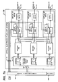
- FIG. 9 shows a generalized example of a virtual electronic fuse system embodying the present invention as VEF system 900.
- VEF system 900 includes elements in common with VEF system 700 of Fig.'s 7A - 7E. Like numbers indicate like elements when comparing these VEF systems.
- VEF system 900 together with fuse programmer 705 form a virtual electronic fuse apparatus 910.
- system 700 of Figures 7A - 7E includes two bit address locations in address pool 715
- system 900 of Figure 9 includes a shared REF address pool 915 with address locations each exhibiting up to M bits, as shown, wherein M is an integer. This permits more virtual electronic fuses (VEFs) and more virtual state changes than the two bit address pool of the embodiment of Fig. 7A - 7E .
- Shared REF address pool 915 includes address locations ADDR(1), ADDR(2), ... ADDR(2 M - 1). Each of these address locations includes M bits, namely bits 1, 2, ... M, as shown in Fig. 9 .
- VEF system 900 includes (2 M - 1) address decoders and virtual electronic fuses (VEFs). VEF system 900 thus forms an array of address locations, decoders, and VEFs. In this embodiment, there is one VEF for each address location in address pool 915.
- the last or highest address location in address pool 915 is ADDR(2 M - 1). Address location (2 M - 1) couples to the last or highest decoder in the array, namely decoder D(2 M - 1).
- VEF(2 M - 1) The last or highest VEF in the array is VEF(2 M - 1).
- Virtual electronic fuse VEF(2 M - 1) includes real electronic fuse REF(2 M - 1), odd/even detector OE(2 M - 1) and latch L(2 M - 1) as shown.
- VEFO(2 M - 1) is the output signal of VEF(2 M - 1).
- Each of decoders D(1), D(2), ... D(2 M - 1) couples to each of the odd/even detectors of VEF(1), VEF(2), .... VEF(2 M - 1).
- decoder D(1) includes outputs that couple to respective odd/even detectors OE(1), OE(2), ...OE(2 M - 1).
- decoder D(2) includes outputs that couple to respective odd/even detectors OE(1), OE(2), ...OE(2 M - 1).
- This topology continues in a similar manner up to decoder D(2 M - 1) that includes outputs that couple to respective odd/even detectors OE(1), OE(2), ...OE(2 M - 1).
- Fig. 9 accommodates 2 M - 1 virtual electronic fuses (VEFs) and permits 2 M - 1 total virtual state changes among those VEFs.
- Fuse programmer 705 may concentrate all 2 M - 1 virtual state changes on a single VEF or may spread the 2 M - 1 virtual state changes across the VEFs of the VEF array.
- VEF system 700 of Figure 7A or VEF system 900 of Figure 9 is usable in place of VEF array 505 in electronic device 500 of Fig. 5A and thus provides alternative embodiments.
- VEF system 700 of Fig. 7A or VEF system 900 of Figure 9 is also usable in place of VEF array 505 in the information handling system (IHS) embodiment shown in Fig. 6 , thus providing yet another embodiment.
- IHS information handling system
- the foregoing discloses a virtual electronic fuse methodology and a virtual electronic fuse apparatus that enables multiple virtual state change operations.
Landscapes
- Engineering & Computer Science (AREA)
- Microelectronics & Electronic Packaging (AREA)
- Semiconductor Integrated Circuits (AREA)
- Design And Manufacture Of Integrated Circuits (AREA)
- Techniques For Improving Reliability Of Storages (AREA)
Claims (4)
- Verfahren zum Ändern des Zustands in einem elektronischen Sicherungssystem (900), wobei das Verfahren Folgendes umfasst:Bereitstellen einer Vielzahl von ersten elektronischen Sicherungen (VEF(1) - VEF(2M - 1)), die jeweils einen durchgebrannten oder einen nicht durchgebrannten Zustand aufweisen können, wobei jede erste Sicherung eine entsprechende Adresse besitzt und jede erste Sicherung eine zweite elektronische Sicherung (REF(1) - REF(2M - 1)) besitzt, die einen nicht durchgebrannten oder einen durchgebrannten Zustand aufweisen kann;in jeder ersten Sicherung Anzeigen des durchgebrannten Zustands oder des nicht durchgebrannten Zustands über einen Detektor (OE(1) - OE(2M - 1)), der mit der zweiten Sicherung verbunden ist, wenn der Detektor eine ungerade Anzahl von Eingangssignalen, die einen ersten logischen Zustand aufweisen, empfängt, und Anzeigen des anderen Zustands von durchgebranntem Zustand und nicht durchgebranntem Zustand über den Detektor, wenn der Detektor eine gerade Anzahl von logischen Signalen, die den ersten logischen Zustand aufweisen, empfängt;Vorsehen einer bestimmten ersten Sicherung für eine Zustandsänderung von dem nicht durchgebrannten Zustand zu dem durchgebrannten Zustand über eine Sicherungs-Programmiereinrichtung (705); undÄndern des Zustands der zweiten Sicherung in der bestimmten ersten Sicherung von einem nicht durchgebrannten Zustand zu einem durchgebrannten Zustand in Reaktion auf die Sicherungs-Programmiereinrichtung, wobei die zweite Sicherung in der bestimmten ersten Sicherung ein erstes Eingangssignal, das den ersten logischen Zustand aufweist, an den Detektor in der bestimmten ersten Sicherung bereitstellt, so dass die bestimmte erste Sicherung den durchgebrannten Zustand aufweist, wobei der Detektor (OE(1) - OE(2M - 1)) der bestimmten ersten Sicherung in der Weise konfiguriert ist, dass das Empfangen des ersten Eingangssignals, das den ersten logischen Zustand aufweist, durch den Detektor dem Empfangen einer ungeraden Anzahl von Eingangssignalen entspricht, so dass die Sicherung den durchgebrannten Zustand aufweist;dadurch gekennzeichnet, dass das Verfahren Folgendes umfasst:Bereitstellen eines Sicherungsadressenvorrats (715), der mit den ersten Sicherungen verbunden ist, wobei der Adressenvorrat eine Vielzahl von Adressenspeicherorten (ADDR(1) - ADDR(2M - 1)) enthält, wobei der Adressenvorrat einen Adressenvorratseingang enthält, der mit der Sicherungsprogrammiereinrichtung verbunden werden kann;Schreiben der Adresse der bestimmten ersten Sicherung an einen Adressenspeicherort in dem Adressenvorrat durch die Sicherungsprogrammiereinrichtung, um einen Zeiger auf die bestimmte erste Sicherung zu bereitzustellen;Bereitstellen einer Vielzahl von Decodierern (D(1) - D(2M - 1)), wobei jeder Decodierer mit einem entsprechenden Adressenspeicherort in dem Adressenvorrat verbunden ist; undSenden durch den Decodierer, der mit dem Adressenspeicherort für die bestimmte erste Sicherung verbunden ist, eines zweiten Eingangssignals, das den ersten logischen Zustand aufweist, an den Detektor der bestimmten ersten Sicherung, so dass der Detektor der bestimmten ersten Sicherung eine geradzahlige Anzahl von Eingangssignalen empfängt und die erste Sicherung in Reaktion darauf den virtuellen nicht durchgebrannten Zustand aufweist.
- Elektronisches Sicherungssystem (900), das Folgendes umfasst:eine Vielzahl von ersten elektronischen Sicherungen (VEF(1) - VEF(2M - 1)), die jeweils einen durchgebrannten oder einen nicht durchgebrannten Zustand aufweisen können, wobei jede erste Sicherung eine entsprechende Adresse besitzt und jede erste Sicherung Folgendes enthält:eine zweite elektronische Sicherung (REF(1) - REF(2M - 1)), die einen nicht durchgebrannten oder einen durchgebrannten Zustand aufweisen kann;einen mit der zweiten Sicherung verbundenen Detektor (OE(1) - OE(2M - 1)), der den durchgebrannten Zustand oder den nicht durchgebrannten Zustand anzeigt, wenn der Detektor eine ungerade Anzahl von Eingangssignalen, die einen ersten logischen Zustand aufweisen, empfängt, und den anderen Zustand von durchgebranntem Zustand und nicht durchgebranntem Zustand anzeigt, wenn der Detektor eine gerade Anzahl von Eingangssignalen, die einen ersten logischen Zustand aufweisen, empfängt;wobei das elektronische Sicherungssystem einen Eingang enthält, der mit einer Sicherungsprogrammiereinrichtung (705) verbunden werden kann, die eine bestimmte erste Sicherung für eine Zustandsänderung von dem nicht durchgebrannten Zustand zu dem durchgebrannten Zustand vorsieht;die zweite Sicherung in der bestimmten ersten Sicherung den Zustand von einem nicht durchgebrannten Zustand zu einem durchgebrannten Zustand in Reaktion auf die Sicherungsprogrammiereinrichtung ändert, wobei die zweite Sicherung in der bestimmten ersten Sicherung ein erstes Eingangssignal, das den ersten logischen Zustand aufweist, an den Detektor in der bestimmten ersten Sicherung bereitstellt, so dass die bestimmte erste Sicherung den durchgebrannten Zustand aufweist; undder Detektor (OE(1) - OE(2M - 1)) der bestimmten ersten Sicherung so konfiguriert ist, dass das Empfangen des ersten Eingangssignals, das den ersten logischen Zustand aufweist, durch den Detektor dem Empfangen einer ungeraden Anzahl von Eingangssignalen entspricht, so dass die erste Sicherung den durchgebrannten Zustand aufweist;dadurch gekennzeichnet, dass das System des Weiteren Folgendes umfasst: einen Sicherungsadressenvorrat (715), der mit den ersten Sicherungen verbunden ist, wobei der Adressenvorrat eine Vielzahl von Adressenspeicherorten (ADDR(1) - ADDR(2M - 1)) enthält, der Adressenvorrat einen Adressenvorratseingang enthält, der mit der Sicherungsprogrammiereinrichtung verbunden werden kann,wobei der Adressenvorrat in der Weise konfiguriert ist, dass die Sicherungsprogrammiereinrichtung die Adresse der bestimmten ersten Sicherung auf einen Adressenspeicherort in dem Adressenvorrat schreiben kann, um auf diese Weise einen Zeiger auf die bestimmte erste Sicherung zu schaffen, und das System des Weiteren eine Vielzahl von Decodierern (D(1) - D(2M - 1)) umfasst, wobei jeder Decodierer mit einem entsprechenden Adressenspeicherort in dem Adressenvorrat verbunden ist, wobei der Decodierer, der mit dem Adressenspeicherort für die bestimmte erste Sicherung verbunden ist, ein zweites Eingangssignal, das den ersten logischen Zustand aufweist, an den Detektor der bestimmten ersten Sicherung sendet, so dass der Detektor der bestimmten ersten Sicherung eine geradzahlige Anzahl von Eingangssignalen empfängt und die erste Sicherung in Reaktion darauf den virtuellen nicht durchgebrannten Zustand aufweist.
- Integrierte Schaltung, die Folgendes umfasst:einen Halbleiterchip; undein elektronisches Sicherungssystem (900) nach Anspruch 2, das auf dem Halbleiterchip angeordnet ist.
- Informationsbearbeitungssystem (600), das Folgendes umfasst:einen Speicher (610);einen Prozessor (515), der mit dem Speicher verbunden ist, wobei der Prozessor auf einem Halbleiterchip angeordnet ist;ein elektronisches Sicherungssystem (505) nach Anspruch 2, das auf dem Halbleiterchip angeordnet ist.
Applications Claiming Priority (2)
| Application Number | Priority Date | Filing Date | Title |
|---|---|---|---|
| US11/674,227 US7515498B2 (en) | 2007-02-13 | 2007-02-13 | Electronic fuse apparatus and methodology including addressable virtual electronic fuses |
| PCT/EP2008/050335 WO2008098808A1 (en) | 2007-02-13 | 2008-01-14 | Electronic fuse apparatus and methodology including addressable virtual electronic fuses |
Publications (2)
| Publication Number | Publication Date |
|---|---|
| EP2118904A1 EP2118904A1 (de) | 2009-11-18 |
| EP2118904B1 true EP2118904B1 (de) | 2011-09-14 |
Family
ID=39345466
Family Applications (1)
| Application Number | Title | Priority Date | Filing Date |
|---|---|---|---|
| EP08707883A Active EP2118904B1 (de) | 2007-02-13 | 2008-01-14 | Elektronische sicherungsvorrichtung und -verfahren mit adressierbare virtuelle elektronische sicherungen |
Country Status (7)
| Country | Link |
|---|---|
| US (1) | US7515498B2 (de) |
| EP (1) | EP2118904B1 (de) |
| JP (1) | JP5260556B2 (de) |
| KR (1) | KR101071794B1 (de) |
| AT (1) | ATE524812T1 (de) |
| TW (1) | TW200849264A (de) |
| WO (1) | WO2008098808A1 (de) |
Families Citing this family (5)
| Publication number | Priority date | Publication date | Assignee | Title |
|---|---|---|---|---|
| JP2010146636A (ja) * | 2008-12-18 | 2010-07-01 | Toshiba Corp | 半導体集積回路装置及びメモリシステム |
| GB2505874B (en) * | 2012-09-03 | 2016-02-03 | Cambridge Silicon Radio Ltd | Programmable memory with restricted reprogrammability |
| US8913454B2 (en) | 2012-10-10 | 2014-12-16 | Cambridge Silicon Radio Limited | Programmable memory with restricted reprogrammability |
| US20170052799A1 (en) * | 2015-08-21 | 2017-02-23 | Microchip Technology Incorporated | Integrated Circuit Device With Selectable Processor Core |
| US20230223337A1 (en) * | 2022-01-11 | 2023-07-13 | Globalfoundries U.S. Inc. | Middle of the line heater and methods |
Family Cites Families (25)
| Publication number | Priority date | Publication date | Assignee | Title |
|---|---|---|---|---|
| US4389715A (en) * | 1980-10-06 | 1983-06-21 | Inmos Corporation | Redundancy scheme for a dynamic RAM |
| JPS62177798A (ja) * | 1986-01-30 | 1987-08-04 | Fujitsu Ltd | 半導体記憶装置 |
| JPS63187498A (ja) * | 1987-01-28 | 1988-08-03 | Nec Corp | 複数回プログラム可能読出し専用メモリ装置 |
| US5206583A (en) | 1991-08-20 | 1993-04-27 | International Business Machines Corporation | Latch assisted fuse testing for customized integrated circuits |
| US5432388A (en) * | 1992-08-27 | 1995-07-11 | At&T Global Information Solutions Company | Repeatedly programmable logic array using dynamic access memory |
| US5966339A (en) * | 1998-06-02 | 1999-10-12 | International Business Machines Corporation | Programmable/reprogrammable fuse |
| JP2000011684A (ja) * | 1998-06-18 | 2000-01-14 | Mitsubishi Electric Corp | 入力保護回路、アンチフューズアドレス検出回路および半導体集積回路装置 |
| US6141245A (en) * | 1999-04-30 | 2000-10-31 | International Business Machines Corporation | Impedance control using fuses |
| US6219215B1 (en) * | 1999-04-30 | 2001-04-17 | International Business Machines Corporation | Chip thermal protection device |
| US6633055B2 (en) * | 1999-04-30 | 2003-10-14 | International Business Machines Corporation | Electronic fuse structure and method of manufacturing |
| US6346846B1 (en) * | 1999-12-17 | 2002-02-12 | International Business Machines Corporation | Methods and apparatus for blowing and sensing antifuses |
| DE10026243C2 (de) * | 2000-05-26 | 2002-04-18 | Infineon Technologies Ag | Verfahren zum Auslesen von elektrischen Fuses/Antifuses |
| JP2002134620A (ja) * | 2000-10-27 | 2002-05-10 | Mitsubishi Electric Corp | 半導体装置 |
| US6384666B1 (en) * | 2001-03-23 | 2002-05-07 | International Business Machines Corporation | Antifuse latch device with controlled current programming and variable trip point |
| US20040124458A1 (en) * | 2002-12-31 | 2004-07-01 | Chandrasekharan Kothandaraman | Programmable fuse device |
| US7089136B2 (en) * | 2003-07-18 | 2006-08-08 | International Business Machines Corporation | Method for reduced electrical fusing time |
| US6933591B1 (en) * | 2003-10-16 | 2005-08-23 | Altera Corporation | Electrically-programmable integrated circuit fuses and sensing circuits |
| US7064946B2 (en) * | 2003-12-18 | 2006-06-20 | International Rectifier Corporation | Electronic fuse |
| US7289382B2 (en) * | 2003-12-23 | 2007-10-30 | Intel Corporation | Rewritable fuse memory |
| US7098721B2 (en) * | 2004-09-01 | 2006-08-29 | International Business Machines Corporation | Low voltage programmable eFuse with differential sensing scheme |
| JP4675082B2 (ja) * | 2004-10-21 | 2011-04-20 | 富士通セミコンダクター株式会社 | 半導体記憶装置および半導体記憶装置の制御方法 |
| JP4646608B2 (ja) * | 2004-11-26 | 2011-03-09 | パナソニック株式会社 | 半導体記憶装置 |
| KR100572622B1 (ko) * | 2004-12-22 | 2006-04-24 | 삼성전자주식회사 | 멀티 타임 프로그래머블 반도체 메모리 장치 및 멀티 타임프로그래머블 반도체 메모리 장치의 멀티 타임 프로그래밍방법 |
| US7129769B2 (en) * | 2005-02-17 | 2006-10-31 | International Business Machines Corporation | Method and apparatus for protecting eFuse information |
| US7298639B2 (en) * | 2005-05-04 | 2007-11-20 | International Business Machines Corporation | Reprogrammable electrical fuse |
-
2007
- 2007-02-13 US US11/674,227 patent/US7515498B2/en active Active
-
2008
- 2008-01-14 JP JP2009548636A patent/JP5260556B2/ja active Active
- 2008-01-14 KR KR1020097010903A patent/KR101071794B1/ko not_active Expired - Fee Related
- 2008-01-14 AT AT08707883T patent/ATE524812T1/de not_active IP Right Cessation
- 2008-01-14 EP EP08707883A patent/EP2118904B1/de active Active
- 2008-01-14 WO PCT/EP2008/050335 patent/WO2008098808A1/en not_active Ceased
- 2008-02-12 TW TW097104760A patent/TW200849264A/zh unknown
Also Published As
| Publication number | Publication date |
|---|---|
| TW200849264A (en) | 2008-12-16 |
| ATE524812T1 (de) | 2011-09-15 |
| JP5260556B2 (ja) | 2013-08-14 |
| EP2118904A1 (de) | 2009-11-18 |
| US7515498B2 (en) | 2009-04-07 |
| KR20090088888A (ko) | 2009-08-20 |
| US20080191780A1 (en) | 2008-08-14 |
| KR101071794B1 (ko) | 2011-10-11 |
| JP2010518540A (ja) | 2010-05-27 |
| WO2008098808A1 (en) | 2008-08-21 |
Similar Documents
| Publication | Publication Date | Title |
|---|---|---|
| US9727478B2 (en) | Apparatus and method for configurable redundant fuse banks | |
| CN104538059B (zh) | 用于在功率选通事件之后恢复数据阵列的多核装置和方法 | |
| EP2118904B1 (de) | Elektronische sicherungsvorrichtung und -verfahren mit adressierbare virtuelle elektronische sicherungen | |
| CN104575610B (zh) | 多核微处理器功率选通高速缓存恢复机制 | |
| US7737763B2 (en) | Virtual electronic fuse apparatus and methodology | |
| US7200743B1 (en) | Simultaneous initialization of a plurality of memory elements from among a plurality of initialization values | |
| EP2840509B1 (de) | Vorrichtung und Verfahren zur Speicherung und Dekompression von Konfigurationsdaten | |
| US9348690B2 (en) | Correctable configuration data compression and decompression system | |
| EP2840490B1 (de) | Kernspezifischer Sicherungsmechanismus für eine Mehrkernmatrize | |
| EP2840491B1 (de) | Verlängerter Sicherungsumprogrammierbarkeitsmechanismus | |
| EP2840507B1 (de) | Vorrichtung und Verfahren für konfigurierbare redundante Sicherungsbanken | |
| EP2840508B1 (de) | Vorrichtung und Verfahren zur erweiterten Cachekorrektur | |
| EP2840510B1 (de) | Vorrichtung und Verfahren für schnellen Sicherungsbankenzugriff in einem Multikernprozessor | |
| US20150058565A1 (en) | Apparatus and method for compression of configuration data |
Legal Events
| Date | Code | Title | Description |
|---|---|---|---|
| PUAI | Public reference made under article 153(3) epc to a published international application that has entered the european phase |
Free format text: ORIGINAL CODE: 0009012 |
|
| 17P | Request for examination filed |
Effective date: 20090717 |
|
| AK | Designated contracting states |
Kind code of ref document: A1 Designated state(s): AT BE BG CH CY CZ DE DK EE ES FI FR GB GR HR HU IE IS IT LI LT LU LV MC MT NL NO PL PT RO SE SI SK TR |
|
| 17Q | First examination report despatched |
Effective date: 20091208 |
|
| DAX | Request for extension of the european patent (deleted) | ||
| GRAP | Despatch of communication of intention to grant a patent |
Free format text: ORIGINAL CODE: EPIDOSNIGR1 |
|
| GRAS | Grant fee paid |
Free format text: ORIGINAL CODE: EPIDOSNIGR3 |
|
| GRAA | (expected) grant |
Free format text: ORIGINAL CODE: 0009210 |
|
| AK | Designated contracting states |
Kind code of ref document: B1 Designated state(s): AT BE BG CH CY CZ DE DK EE ES FI FR GB GR HR HU IE IS IT LI LT LU LV MC MT NL NO PL PT RO SE SI SK TR |
|
| REG | Reference to a national code |
Ref country code: GB Ref legal event code: FG4D |
|
| REG | Reference to a national code |
Ref country code: CH Ref legal event code: NV Representative=s name: IBM RESEARCH GMBH ZURICH RESEARCH LABORATORY INTEL Ref country code: CH Ref legal event code: EP |
|
| REG | Reference to a national code |
Ref country code: IE Ref legal event code: FG4D |
|
| REG | Reference to a national code |
Ref country code: DE Ref legal event code: R096 Ref document number: 602008009780 Country of ref document: DE Effective date: 20111117 |
|
| REG | Reference to a national code |
Ref country code: GB Ref legal event code: 746 Effective date: 20111101 |
|
| REG | Reference to a national code |
Ref country code: DE Ref legal event code: R084 Ref document number: 602008009780 Country of ref document: DE Effective date: 20111006 |
|
| REG | Reference to a national code |
Ref country code: NL Ref legal event code: VDEP Effective date: 20110914 |
|
| PG25 | Lapsed in a contracting state [announced via postgrant information from national office to epo] |
Ref country code: SE Free format text: LAPSE BECAUSE OF FAILURE TO SUBMIT A TRANSLATION OF THE DESCRIPTION OR TO PAY THE FEE WITHIN THE PRESCRIBED TIME-LIMIT Effective date: 20110914 Ref country code: NO Free format text: LAPSE BECAUSE OF FAILURE TO SUBMIT A TRANSLATION OF THE DESCRIPTION OR TO PAY THE FEE WITHIN THE PRESCRIBED TIME-LIMIT Effective date: 20111214 Ref country code: FI Free format text: LAPSE BECAUSE OF FAILURE TO SUBMIT A TRANSLATION OF THE DESCRIPTION OR TO PAY THE FEE WITHIN THE PRESCRIBED TIME-LIMIT Effective date: 20110914 Ref country code: LT Free format text: LAPSE BECAUSE OF FAILURE TO SUBMIT A TRANSLATION OF THE DESCRIPTION OR TO PAY THE FEE WITHIN THE PRESCRIBED TIME-LIMIT Effective date: 20110914 Ref country code: HR Free format text: LAPSE BECAUSE OF FAILURE TO SUBMIT A TRANSLATION OF THE DESCRIPTION OR TO PAY THE FEE WITHIN THE PRESCRIBED TIME-LIMIT Effective date: 20110914 |
|
| LTIE | Lt: invalidation of european patent or patent extension |
Effective date: 20110914 |
|
| PG25 | Lapsed in a contracting state [announced via postgrant information from national office to epo] |
Ref country code: SI Free format text: LAPSE BECAUSE OF FAILURE TO SUBMIT A TRANSLATION OF THE DESCRIPTION OR TO PAY THE FEE WITHIN THE PRESCRIBED TIME-LIMIT Effective date: 20110914 Ref country code: AT Free format text: LAPSE BECAUSE OF FAILURE TO SUBMIT A TRANSLATION OF THE DESCRIPTION OR TO PAY THE FEE WITHIN THE PRESCRIBED TIME-LIMIT Effective date: 20110914 Ref country code: CY Free format text: LAPSE BECAUSE OF FAILURE TO SUBMIT A TRANSLATION OF THE DESCRIPTION OR TO PAY THE FEE WITHIN THE PRESCRIBED TIME-LIMIT Effective date: 20110914 Ref country code: GR Free format text: LAPSE BECAUSE OF FAILURE TO SUBMIT A TRANSLATION OF THE DESCRIPTION OR TO PAY THE FEE WITHIN THE PRESCRIBED TIME-LIMIT Effective date: 20111215 Ref country code: LV Free format text: LAPSE BECAUSE OF FAILURE TO SUBMIT A TRANSLATION OF THE DESCRIPTION OR TO PAY THE FEE WITHIN THE PRESCRIBED TIME-LIMIT Effective date: 20110914 |
|
| REG | Reference to a national code |
Ref country code: AT Ref legal event code: MK05 Ref document number: 524812 Country of ref document: AT Kind code of ref document: T Effective date: 20110914 |
|
| PG25 | Lapsed in a contracting state [announced via postgrant information from national office to epo] |
Ref country code: BE Free format text: LAPSE BECAUSE OF FAILURE TO SUBMIT A TRANSLATION OF THE DESCRIPTION OR TO PAY THE FEE WITHIN THE PRESCRIBED TIME-LIMIT Effective date: 20110914 |
|
| PG25 | Lapsed in a contracting state [announced via postgrant information from national office to epo] |
Ref country code: CZ Free format text: LAPSE BECAUSE OF FAILURE TO SUBMIT A TRANSLATION OF THE DESCRIPTION OR TO PAY THE FEE WITHIN THE PRESCRIBED TIME-LIMIT Effective date: 20110914 Ref country code: SK Free format text: LAPSE BECAUSE OF FAILURE TO SUBMIT A TRANSLATION OF THE DESCRIPTION OR TO PAY THE FEE WITHIN THE PRESCRIBED TIME-LIMIT Effective date: 20110914 Ref country code: IS Free format text: LAPSE BECAUSE OF FAILURE TO SUBMIT A TRANSLATION OF THE DESCRIPTION OR TO PAY THE FEE WITHIN THE PRESCRIBED TIME-LIMIT Effective date: 20120114 |
|
| PGFP | Annual fee paid to national office [announced via postgrant information from national office to epo] |
Ref country code: FR Payment date: 20120130 Year of fee payment: 5 |
|
| PG25 | Lapsed in a contracting state [announced via postgrant information from national office to epo] |
Ref country code: NL Free format text: LAPSE BECAUSE OF FAILURE TO SUBMIT A TRANSLATION OF THE DESCRIPTION OR TO PAY THE FEE WITHIN THE PRESCRIBED TIME-LIMIT Effective date: 20110914 Ref country code: RO Free format text: LAPSE BECAUSE OF FAILURE TO SUBMIT A TRANSLATION OF THE DESCRIPTION OR TO PAY THE FEE WITHIN THE PRESCRIBED TIME-LIMIT Effective date: 20110914 Ref country code: PT Free format text: LAPSE BECAUSE OF FAILURE TO SUBMIT A TRANSLATION OF THE DESCRIPTION OR TO PAY THE FEE WITHIN THE PRESCRIBED TIME-LIMIT Effective date: 20120116 Ref country code: PL Free format text: LAPSE BECAUSE OF FAILURE TO SUBMIT A TRANSLATION OF THE DESCRIPTION OR TO PAY THE FEE WITHIN THE PRESCRIBED TIME-LIMIT Effective date: 20110914 Ref country code: EE Free format text: LAPSE BECAUSE OF FAILURE TO SUBMIT A TRANSLATION OF THE DESCRIPTION OR TO PAY THE FEE WITHIN THE PRESCRIBED TIME-LIMIT Effective date: 20110914 Ref country code: IT Free format text: LAPSE BECAUSE OF FAILURE TO SUBMIT A TRANSLATION OF THE DESCRIPTION OR TO PAY THE FEE WITHIN THE PRESCRIBED TIME-LIMIT Effective date: 20110914 |
|
| PLBE | No opposition filed within time limit |
Free format text: ORIGINAL CODE: 0009261 |
|
| STAA | Information on the status of an ep patent application or granted ep patent |
Free format text: STATUS: NO OPPOSITION FILED WITHIN TIME LIMIT |
|
| PG25 | Lapsed in a contracting state [announced via postgrant information from national office to epo] |
Ref country code: DK Free format text: LAPSE BECAUSE OF FAILURE TO SUBMIT A TRANSLATION OF THE DESCRIPTION OR TO PAY THE FEE WITHIN THE PRESCRIBED TIME-LIMIT Effective date: 20110914 |
|
| 26N | No opposition filed |
Effective date: 20120615 |
|
| PG25 | Lapsed in a contracting state [announced via postgrant information from national office to epo] |
Ref country code: MC Free format text: LAPSE BECAUSE OF NON-PAYMENT OF DUE FEES Effective date: 20120131 |
|
| REG | Reference to a national code |
Ref country code: CH Ref legal event code: PL |
|
| REG | Reference to a national code |
Ref country code: DE Ref legal event code: R097 Ref document number: 602008009780 Country of ref document: DE Effective date: 20120615 |
|
| REG | Reference to a national code |
Ref country code: IE Ref legal event code: MM4A |
|
| PG25 | Lapsed in a contracting state [announced via postgrant information from national office to epo] |
Ref country code: LI Free format text: LAPSE BECAUSE OF NON-PAYMENT OF DUE FEES Effective date: 20120131 Ref country code: CH Free format text: LAPSE BECAUSE OF NON-PAYMENT OF DUE FEES Effective date: 20120131 |
|
| PG25 | Lapsed in a contracting state [announced via postgrant information from national office to epo] |
Ref country code: IE Free format text: LAPSE BECAUSE OF NON-PAYMENT OF DUE FEES Effective date: 20120114 |
|
| PG25 | Lapsed in a contracting state [announced via postgrant information from national office to epo] |
Ref country code: ES Free format text: LAPSE BECAUSE OF FAILURE TO SUBMIT A TRANSLATION OF THE DESCRIPTION OR TO PAY THE FEE WITHIN THE PRESCRIBED TIME-LIMIT Effective date: 20111225 |
|
| PG25 | Lapsed in a contracting state [announced via postgrant information from national office to epo] |
Ref country code: BG Free format text: LAPSE BECAUSE OF FAILURE TO SUBMIT A TRANSLATION OF THE DESCRIPTION OR TO PAY THE FEE WITHIN THE PRESCRIBED TIME-LIMIT Effective date: 20111214 |
|
| PG25 | Lapsed in a contracting state [announced via postgrant information from national office to epo] |
Ref country code: MT Free format text: LAPSE BECAUSE OF FAILURE TO SUBMIT A TRANSLATION OF THE DESCRIPTION OR TO PAY THE FEE WITHIN THE PRESCRIBED TIME-LIMIT Effective date: 20110914 |
|
| REG | Reference to a national code |
Ref country code: FR Ref legal event code: ST Effective date: 20130930 |
|
| PG25 | Lapsed in a contracting state [announced via postgrant information from national office to epo] |
Ref country code: FR Free format text: LAPSE BECAUSE OF NON-PAYMENT OF DUE FEES Effective date: 20130131 |
|
| PG25 | Lapsed in a contracting state [announced via postgrant information from national office to epo] |
Ref country code: TR Free format text: LAPSE BECAUSE OF FAILURE TO SUBMIT A TRANSLATION OF THE DESCRIPTION OR TO PAY THE FEE WITHIN THE PRESCRIBED TIME-LIMIT Effective date: 20110914 |
|
| PG25 | Lapsed in a contracting state [announced via postgrant information from national office to epo] |
Ref country code: LU Free format text: LAPSE BECAUSE OF NON-PAYMENT OF DUE FEES Effective date: 20120114 |
|
| PG25 | Lapsed in a contracting state [announced via postgrant information from national office to epo] |
Ref country code: HU Free format text: LAPSE BECAUSE OF FAILURE TO SUBMIT A TRANSLATION OF THE DESCRIPTION OR TO PAY THE FEE WITHIN THE PRESCRIBED TIME-LIMIT Effective date: 20080114 |
|
| REG | Reference to a national code |
Ref country code: DE Ref legal event code: R082 Ref document number: 602008009780 Country of ref document: DE Representative=s name: KUISMA, SIRPA, FI |
|
| P01 | Opt-out of the competence of the unified patent court (upc) registered |
Effective date: 20230423 |
|
| PGFP | Annual fee paid to national office [announced via postgrant information from national office to epo] |
Ref country code: DE Payment date: 20241216 Year of fee payment: 18 |
|
| PGFP | Annual fee paid to national office [announced via postgrant information from national office to epo] |
Ref country code: GB Payment date: 20250129 Year of fee payment: 18 |