EP2118801B1 - Verfahren und vorrichtung zur bereitstellung einer graphischen benutzerschnittstelle zur datenerfassung und datendarstellung - Google Patents
Verfahren und vorrichtung zur bereitstellung einer graphischen benutzerschnittstelle zur datenerfassung und datendarstellung Download PDFInfo
- Publication number
- EP2118801B1 EP2118801B1 EP07849566.0A EP07849566A EP2118801B1 EP 2118801 B1 EP2118801 B1 EP 2118801B1 EP 07849566 A EP07849566 A EP 07849566A EP 2118801 B1 EP2118801 B1 EP 2118801B1
- Authority
- EP
- European Patent Office
- Prior art keywords
- data
- measurement
- substrate
- optionally
- probe
- Prior art date
- Legal status (The legal status is an assumption and is not a legal conclusion. Google has not performed a legal analysis and makes no representation as to the accuracy of the status listed.)
- Active
Links
- 238000000034 method Methods 0.000 title claims description 66
- 239000000523 sample Substances 0.000 claims description 150
- 238000005259 measurement Methods 0.000 claims description 134
- 238000012545 processing Methods 0.000 claims description 9
- 238000012512 characterization method Methods 0.000 claims description 8
- 239000007787 solid Substances 0.000 claims description 8
- 230000008569 process Effects 0.000 claims description 5
- 230000004913 activation Effects 0.000 claims description 4
- 238000012544 monitoring process Methods 0.000 claims 2
- 239000000758 substrate Substances 0.000 description 199
- 210000001519 tissue Anatomy 0.000 description 35
- 238000005520 cutting process Methods 0.000 description 20
- 239000003550 marker Substances 0.000 description 17
- 238000004458 analytical method Methods 0.000 description 12
- 238000010586 diagram Methods 0.000 description 10
- 238000002604 ultrasonography Methods 0.000 description 10
- 238000001514 detection method Methods 0.000 description 9
- 238000003860 storage Methods 0.000 description 9
- 230000009471 action Effects 0.000 description 8
- 230000000875 corresponding effect Effects 0.000 description 7
- 239000000126 substance Substances 0.000 description 7
- 238000005516 engineering process Methods 0.000 description 6
- 238000003384 imaging method Methods 0.000 description 6
- 238000013507 mapping Methods 0.000 description 6
- 239000000463 material Substances 0.000 description 6
- 238000013480 data collection Methods 0.000 description 5
- 238000002059 diagnostic imaging Methods 0.000 description 5
- 238000011156 evaluation Methods 0.000 description 5
- 239000011159 matrix material Substances 0.000 description 5
- 238000001356 surgical procedure Methods 0.000 description 5
- 230000002596 correlated effect Effects 0.000 description 4
- 230000006870 function Effects 0.000 description 4
- 230000007246 mechanism Effects 0.000 description 4
- 230000005855 radiation Effects 0.000 description 4
- 230000004044 response Effects 0.000 description 4
- 238000005070 sampling Methods 0.000 description 4
- 206010028980 Neoplasm Diseases 0.000 description 3
- 230000002159 abnormal effect Effects 0.000 description 3
- 238000007405 data analysis Methods 0.000 description 3
- 238000003745 diagnosis Methods 0.000 description 3
- 239000003814 drug Substances 0.000 description 3
- 230000006698 induction Effects 0.000 description 3
- 238000003780 insertion Methods 0.000 description 3
- 230000037431 insertion Effects 0.000 description 3
- 230000003287 optical effect Effects 0.000 description 3
- 210000000056 organ Anatomy 0.000 description 3
- 238000004806 packaging method and process Methods 0.000 description 3
- 238000003825 pressing Methods 0.000 description 3
- 238000003325 tomography Methods 0.000 description 3
- 238000010521 absorption reaction Methods 0.000 description 2
- 239000003086 colorant Substances 0.000 description 2
- 238000004891 communication Methods 0.000 description 2
- 238000013479 data entry Methods 0.000 description 2
- 229940079593 drug Drugs 0.000 description 2
- 230000005670 electromagnetic radiation Effects 0.000 description 2
- 238000002513 implantation Methods 0.000 description 2
- 230000010354 integration Effects 0.000 description 2
- 238000000691 measurement method Methods 0.000 description 2
- 238000012986 modification Methods 0.000 description 2
- 230000004048 modification Effects 0.000 description 2
- 230000000149 penetrating effect Effects 0.000 description 2
- 230000001052 transient effect Effects 0.000 description 2
- 238000011179 visual inspection Methods 0.000 description 2
- 238000012935 Averaging Methods 0.000 description 1
- 241000295146 Gallionellaceae Species 0.000 description 1
- 238000002679 ablation Methods 0.000 description 1
- 230000005856 abnormality Effects 0.000 description 1
- 230000003213 activating effect Effects 0.000 description 1
- 230000006978 adaptation Effects 0.000 description 1
- 238000003491 array Methods 0.000 description 1
- 230000008901 benefit Effects 0.000 description 1
- 230000004071 biological effect Effects 0.000 description 1
- 230000005540 biological transmission Effects 0.000 description 1
- 238000002725 brachytherapy Methods 0.000 description 1
- 230000008859 change Effects 0.000 description 1
- 238000006243 chemical reaction Methods 0.000 description 1
- 125000004122 cyclic group Chemical group 0.000 description 1
- 230000003247 decreasing effect Effects 0.000 description 1
- 230000003111 delayed effect Effects 0.000 description 1
- 238000002405 diagnostic procedure Methods 0.000 description 1
- 238000009826 distribution Methods 0.000 description 1
- 239000000835 fiber Substances 0.000 description 1
- 238000002594 fluoroscopy Methods 0.000 description 1
- 238000010191 image analysis Methods 0.000 description 1
- 238000013275 image-guided biopsy Methods 0.000 description 1
- 230000036512 infertility Effects 0.000 description 1
- 230000000977 initiatory effect Effects 0.000 description 1
- 238000002347 injection Methods 0.000 description 1
- 239000007924 injection Substances 0.000 description 1
- 229910052500 inorganic mineral Inorganic materials 0.000 description 1
- 230000003993 interaction Effects 0.000 description 1
- 230000003902 lesion Effects 0.000 description 1
- 230000004807 localization Effects 0.000 description 1
- 230000003211 malignant effect Effects 0.000 description 1
- 238000002483 medication Methods 0.000 description 1
- 239000011707 mineral Substances 0.000 description 1
- 238000002324 minimally invasive surgery Methods 0.000 description 1
- 239000000203 mixture Substances 0.000 description 1
- 206010033675 panniculitis Diseases 0.000 description 1
- 230000007170 pathology Effects 0.000 description 1
- 230000010287 polarization Effects 0.000 description 1
- 230000001902 propagating effect Effects 0.000 description 1
- 238000012827 research and development Methods 0.000 description 1
- 238000012883 sequential measurement Methods 0.000 description 1
- 230000005236 sound signal Effects 0.000 description 1
- 238000001228 spectrum Methods 0.000 description 1
- 210000004304 subcutaneous tissue Anatomy 0.000 description 1
- 238000001931 thermography Methods 0.000 description 1
- 238000012285 ultrasound imaging Methods 0.000 description 1
- 230000000007 visual effect Effects 0.000 description 1
Images


Classifications
-
- G—PHYSICS
- G16—INFORMATION AND COMMUNICATION TECHNOLOGY [ICT] SPECIALLY ADAPTED FOR SPECIFIC APPLICATION FIELDS
- G16H—HEALTHCARE INFORMATICS, i.e. INFORMATION AND COMMUNICATION TECHNOLOGY [ICT] SPECIALLY ADAPTED FOR THE HANDLING OR PROCESSING OF MEDICAL OR HEALTHCARE DATA
- G16H10/00—ICT specially adapted for the handling or processing of patient-related medical or healthcare data
- G16H10/20—ICT specially adapted for the handling or processing of patient-related medical or healthcare data for electronic clinical trials or questionnaires
-
- G—PHYSICS
- G16—INFORMATION AND COMMUNICATION TECHNOLOGY [ICT] SPECIALLY ADAPTED FOR SPECIFIC APPLICATION FIELDS
- G16H—HEALTHCARE INFORMATICS, i.e. INFORMATION AND COMMUNICATION TECHNOLOGY [ICT] SPECIALLY ADAPTED FOR THE HANDLING OR PROCESSING OF MEDICAL OR HEALTHCARE DATA
- G16H15/00—ICT specially adapted for medical reports, e.g. generation or transmission thereof
-
- G—PHYSICS
- G16—INFORMATION AND COMMUNICATION TECHNOLOGY [ICT] SPECIALLY ADAPTED FOR SPECIFIC APPLICATION FIELDS
- G16H—HEALTHCARE INFORMATICS, i.e. INFORMATION AND COMMUNICATION TECHNOLOGY [ICT] SPECIALLY ADAPTED FOR THE HANDLING OR PROCESSING OF MEDICAL OR HEALTHCARE DATA
- G16H40/00—ICT specially adapted for the management or administration of healthcare resources or facilities; ICT specially adapted for the management or operation of medical equipment or devices
- G16H40/60—ICT specially adapted for the management or administration of healthcare resources or facilities; ICT specially adapted for the management or operation of medical equipment or devices for the operation of medical equipment or devices
- G16H40/63—ICT specially adapted for the management or administration of healthcare resources or facilities; ICT specially adapted for the management or operation of medical equipment or devices for the operation of medical equipment or devices for local operation
Definitions
- Embodiments of the invention relate generally to graphical user interfaces (GUI), methods and apparatus useful in presentation of data.
- GUI graphical user interfaces
- U.S. Patents 5,807,257 ; 5,704,355 and 6,061,589 describe use of millimeter and microwave devices to measure bioimpedance and to detect abnormal tissue. These methods direct a free propagating radiation, or a guided radiation via waveguide, onto the organ. The radiation is focused on a relatively small volume inside the organ, and the reflected radiation is then measured.
- U.S. Patent 6,109,270 describes a measurement concept with a multi-modality instrument for tissue identification in real-time neuro-surgical applications.
- U.S. Patents 6,813,515 ; 7082325 and 7,184,824 U.S. Patent Applications published as 20070260156 ; 20070255169 ; 20070179397 ; 20070032747 ; 20070032739 ; 20060264738 ; 20060253107 ; 20050021019 ; 20030187366 and 20030138378 describe tools systems and methods useful in assessing tissue type and/or identifying tumor margins.
- U.S. Patent 5,615,132 describes a method and apparatus for determining position and orientation of a moveable object using accelerometers.
- U.S. Patent 6,833,814 describes an intrabody navigation system for medical applications in which three planar antennas that at least partly overlap are used to transmit electromagnetic radiation simultaneously.
- Ascension Technology Corp. (Burlington VT, USA) markets a guide for localizing medical instruments with 3D magnetic tracking as "3D Guidance TM Medsafe” .
- a broad aspect of the invention relates to integrating image and/or data (which may be biological, chemical and/or physical data) with planning and/or execution of a procedure.
- the image data may be, for example, X-ray based (e.g. Fluorography, or computerized tomography [CT]), ultrasound based or magnetic resonance induction (MRI) based.
- CT computerized tomography
- MRI magnetic resonance induction
- image refers to data representation indicative of the properties of an examined/measured subject (or substrate) within a region of interest, e.g. tissue region.
- the examined/measured properties of the subject may include optical, electrical, geometrical characteristics of the subject within the region of interest.
- the obtained image does not necessarily presents a continuous distribution of the required property or properties all along the region of interest, but in most cases is in the form of a plurality of data pieces corresponding to discrete measurement sites within the region of interest.
- a graphical user interface presents data in meaningful groups to a user. More specifically, the present invention deals with medical data (for example data pertaining to excised tissue) and is therefore described below with respect to this specific application. It should, however, be understood that the invention is not limited to this application and the inventive aspects can be used for various other applications as well.
- grouped data pertaining to excised tissue is presented to a user in an operating room, optionally during an excision procedure.
- presentation of data for a group includes a collection of individual data and/or one or more statistics which summarize the group.
- Another aspect of some embodiments of the invention relates to an apparatus configured and operable to group data pertaining to individual points on a substrate into groups during data acquisition.
- a user provides input pertaining to group definitions.
- group definitions are selected from a list and/or defined by the user (i.e. "from scratch").
- grouped data is presented graphically on a display screen.
- the grouped data is presented superimposed on a representation of the substrate.
- the representation of the substrate can be, for example a theoretical representation (e.g. a cube), a simplified solid form or an image of the substrate.
- common imaging modalities include, but are not limited to ultrasound imaging, fluoroscopy, computerized tomography (CT), magnetic resonance induction (MRI), impedance based and other electrical signal based measurements.
- images are prepared concurrently with data acquisition.
- a previously acquired image is employed.
- decreasing an elapsed time between image acquisition and acquisition of other data to be registered onto an image contributes to an increase in accuracy of registration.
- group and/or positional and/or point characterization data is stored in an available memory.
- An aspect of some embodiments of the invention pertains to user selection of locations on a substrate for data collection and user grouping of the locations into groups.
- the user groups the locations into groups using an input device on a hand held data collection probe.
- the substrate includes an excised tissue mass and/or a cavity from which tissue has been excised.
- user grouping of the locations into groups is indicative of approximate positions of the locations on the substrate.
- An aspect of some embodiments of the invention relates to determination of relative position between locations on a substrate and a previously placed marker.
- the marker is placed during image guided localization.
- a measurement of a relative position between a data collection probe and the marker is made substantially as data is being collected at the location.
- the measurement of relative position can be made by signal strength evaluation and/or signal orientation/polarization and/or use of external position sensors and/or image analysis and/or use of overlapping planar antennas.
- An aspect of some embodiments of the invention relates to a hand held device adapted to gather data from a plurality of substrate locations and group the data into user defined groups.
- a user input mechanism on the device allows grouping the data into groups.
- the hand held device is connectable to an external data analysis unit and/or an external vacuum pump.
- the hand held device is sterilized and/or is provided in sterile packaging.
- An aspect of some embodiments of the invention relates to presenting data indicative of substrate status on a model of the substrate.
- a single probe gathers data on substrate status and position coordinates concurrently.
- a user indicates a position for each data point.
- the model is a predefined geometric model (e.g. a cube, tube, cylinder or sphere) or a realistic model (e.g. based on a medical image).
- An aspect of some embodiments of the invention relates to integration of position data with data indicative of substrate status for planning and/or execution of a procedure on the substrate and/or surrounding material.
- the position data indicates a position of a probe providing the data indicative of substrate status at the time a specific datum is acquired and/or a position of a tool.
- the tool can be a cutting tool and/or a sampling tool.
- integration of position data with data indicative of substrate status is used in planning and/or execution of a procedure on the substrate and/or surrounding region.
- a graphical user interface includes: (a) a group definition module (software and/or hardware utility) adapted to accept a user input defining groups; (b) a data receiver operable to receive a plurality of individual measurement input datum indicative of status of a substrate; (c) a grouping module (utility) configured to assign each of the individual measurement input datum to one of the groups to produce grouped data; and (d) an output module (utility) adapted to output the grouped data.
- a group definition module software and/or hardware utility
- a data receiver operable to receive a plurality of individual measurement input datum indicative of status of a substrate
- a grouping module configured to assign each of the individual measurement input datum to one of the groups to produce grouped data
- an output module (utility) adapted to output the grouped data.
- an apparatus in some exemplary embodiments of the invention, includes: (a) a probe operable to produce a plurality of individual signal datum indicative of substrate status; (b) a group definition module adapted to accept a user input defining groups; (c) a grouping module configured to receive the signal includes the individual datum and assign each of the individual datum to one of the groups to produce grouped data; and (d) an output module adapted to output the grouped data.
- a method of analyzing a substrate includes: (a) selecting a plurality of locations on a substrate; (b) collecting a datum indicative of substrate status at each of the locations; and (c) grouping the datum into user defined groups.
- a substrate analysis system includes: (a) a substrate position indicator positioned at the substrate; (b) a probe operable to evaluate substrate status and output status indicative datum at individual points; (c) a measurement module configured to determine a relative position of the position indicator and the probe; and (d) a controller adapted to coordinate operation of the probe and the measurement module so that the relative position is determined for each of the individual points.
- a surgical supervision system includes: (a) an input module adapted to receive a path from a procedure planning as described herein; and (b) a guidance system adapted to output guidance instructions to guide a surgical tool in accordance with the path.
- a substrate probe the probe includes: (a) a data acquisition module adapted to engage a substrate at a user selected point, analyze the substrate and produce a datum indicative of substrate status at the point; (b) a user input device adapted to accept a user input defining groups; (c) a signal conduit adapted to relay electrical signals; and (d) a lumen adapted to relay a negative pressure from an external vacuum source to the data acquisition module.
- a substrate probe the probe includes: (a) a data acquisition module adapted to engage a substrate at a user selected point, analyze the substrate and produce a datum indicative of substrate status at the point; (b) a position determination module adapted to provide a position of the point; (c) a user input device; (d) a signal conduit adapted to relay electrical signals; and (e) a lumen adapted to relay a negative pressure from an external vacuum source to the data acquisition module.
- an apparatus for analysis of a substrate includes: (a) a probe operable to produce a plurality of individual signal datum indicative of substrate status at specified locations; (b) a modeling module adapted to produce a three dimensional model of the substrate; (c) a registration module adapted to indicate the specified locations on the model; and (d) an output module adapted to present an indication of substrate status at each of the specified location on the model.
- a registration module registers the grouped data onto an item selected from the group consisting of a solid representation of the substrate, a space filling model of the substrate and an image of the substrate (e.g. a three dimensional image of the substrate).
- the user input includes a start command and a stop command.
- the user input includes a name.
- the name is indicative of a location on the substrate.
- the names are presented in nested menus.
- the individual datum indicative of status of the substrate are linked to position coordinates.
- the position coordinates are defined relative to the substrate.
- the output of the grouped data includes the individual datum arranged in groups.
- the output of the grouped data includes at least one statistic summarizing the individual datum in each of the groups.
- a memory module adapted to store grouped data output by the output module is included.
- the data receiver is adapted to receive individual measurement input datum concurrently from an array of probes.
- the user input is provided at a time selected from before, during and after receipt of the plurality of individual measurement input datum by the data receiver.
- At least one user input mechanism on the probe is included.
- At least one indicator on the probe is included
- the output module includes a display.
- the output module includes a memory.
- the probe is adapted to measure dielectric properties of the substrate.
- the probe is adapted to measure electromagnetic properties of the substrate.
- the probe is manually operable.
- the plurality of individual datum indicative of substrate status is correlated to manually selected locations on the substrate.
- the user input is indicative of a location on the substrate.
- the probe includes a plurality of sub-probes arranged in a spatial array, the sub-probes collectively operable by a single probe activation signal.
- the probe is operable in at least two sensing/characterization modalities.
- the selecting includes visual inspection.
- the datum indicative of substrate status includes an evaluation of dielectric properties.
- the datum indicative of substrate status includes an evaluation of electromagnetic properties.
- embodiments of the invention include outputting the groups.
- embodiments of the invention include computing at least one statistic summarizing the individual datum in each of the groups and outputting the at least one statistic.
- embodiments of the invention include mapping the groups onto a representation of the substrate.
- the mapping is onto a representation of the substrate selected from the group consisting of a solid representation of the substrate, a space filling model of the substrate and an image of the substrate.
- the user defined groups are each indicative of a location on the substrate.
- embodiments of the invention include defining position coordinates for each of the locations on the substrate.
- the signal originates from the probe and is received at the position indicator.
- the signal originates from the position indicator and is received at the probe.
- embodiments of the invention include a position sensor adapted to determine a first probe position and a second substrate position indicator position; wherein the measurement module determines the relative position by comparing the first and second positions.
- a substrate analysis system includes an imaging module adapted to produce an image depicting the probe and the position indicator; wherein the measurement module determines the relative position from the image.
- a substrate analysis system includes a registration module adapted to register the status indicative datum from the individual points with medical image data.
- a substrate analysis system includes a registration module adapted to register local summaries of status indicative datum with medical image data.
- exemplary embodiments of the invention include a cutting tool mounted on the probe.
- an exemplary embodiment of the invention includes an output module adapted to output the relative position together with the status indicative datum for each of the individual points.
- a procedure planning module is included.
- the procedure planning module is adapted to analyze the output from the output module and calculate a path.
- the procedure planning module is adapted to accept user input pertaining to a planned path.
- probes in some embodiments of the invention include a connector to an external data analysis component.
- probes in some embodiments of the invention are provided as a sterile medical device.
- the user input device is configured to group the datum into groups of data.
- a user perceptible indicator of the substrate status is provided on the probe.
- the user perceptible indicator produces an audible indication.
- the user perceptible indicator produces a visible indication.
- some embodiments of the invention are adapted to accept a user input specifying a position of the locations.
- some embodiments of the invention are adapted to determine a position of the locations.
- some embodiments of the invention include a position sensor adapted to determine a position of the locations.
- a model employed by embodiments of the invention includes a predefined geometric model.
- a model employed by embodiments of the invention includes a realistic model indicative of actual substrate shape.
- embodiments of the invention are adapted to accept medical image data as an input and generate the realistic model from the medical image data.
- the output is directed to an item selected from the group consisting of a graphic display, a printer and a memory.
- method refers to manners, means, techniques and procedures for accomplishing a given task including, but not limited to, those manners, means, techniques and procedures either known to, or readily developed from known manners, means, techniques and procedures by practitioners of architecture and/or computer science.
- Implementation of the method and system of the present invention involves performing or completing selected tasks or steps manually, automatically, or a combination thereof.
- several selected steps could be implemented by hardware or by software on any operating system of any firmware or a combination thereof.
- selected steps of the invention could be implemented as a chip or a circuit.
- selected steps of the invention could be implemented as a plurality of software instructions being executed by a computer using any suitable operating system.
- selected steps of the method and system of the invention could be described as being performed by a data processor, such as a computing platform for executing a plurality of instructions. The invention will be carried out according to the appended independent claims.
- Various embodiments of the invention relate to computerized analytic systems, data acquisition tools for use in conjunction with the systems, and user interfaces adapted for data entry and/or data presentation. Specifically, some embodiments of the invention can be used to define and present individual data points in groups and/or to map data to a model of a substrate (region of interest) on which data points reside.
- Fig. 1 is a schematic diagram of an exemplary system 100 according to one embodiment of the invention.
- Depicted system 100 includes a data acquisition device or measurement unit (depicted as probe 40 ) .
- the probe 40 includes an operative portion 42 for scanning the substrate to be measured (contact or contactless scanning), and is configured and operable to measure and/or characterize one or more parameters indicative of one or more conditions or properties of the substrate in the scanned sites thereof.
- the substrate is a biological tissue, for example a piece of tissue excised from a subject during a surgical procedure.
- the substrate is a mineral substrate, for example a block of material removed from a quarry or mine.
- probe 40 is configured to measure one or more of electromagnetic properties (e.g. using a nonirradiative sensor), dielectric properties, impedance, biological properties, chemical properties, optical properties (e.g. fluorescence emission and/or absorption and/or reflectance of selected wavelengths of light), MRI, energy transmission and/or reflectance (e.g. radio frequency [RF] or microwave [MW]) and temperature (e.g. via infrared thermography).
- electromagnetic properties e.g. using a nonirradiative sensor
- dielectric properties e.g. using a nonirradiative sensor
- impedance e.g. fluorescence emission and/or absorption and/or reflectance of selected wavelengths of light
- MRI e.g. radio frequency [RF] or microwave [MW]
- temperature e.g. via infrared thermography
- probe 40 is configured as a dielectric-property sensor, formed substantially as a coaxial cable.
- probe 40 includes a single sensor at operative portion 42. In other exemplary embodiments of the invention probe 40 includes an array of sensors at operative portion 42.
- operative portion 42 includes a cutting tool and/or a sampling tool.
- the cutting and/or sampling tool is separately controllable.
- a controller operates the cutting and/or sampling tool responsive to data provided by the sensors.
- probe 40 includes or is associated with a control utility including inter alia one or more operative memory utilities 47, a main database storage utility 48, one or more control buttons 43 (e.g. for activating probe 40 and/or for initiating and/or measuring/characterization process, as well as a data processing utility (not shown here).
- probe 40 may include one or more light sources such (depicted as LEDs 45 and 46 ), an indicator or a display 1 (e.g. an LCD or CRT).
- display 1 is used to display results and/or information pertinent to diagnosis and/or surgical planning.
- results and/or information from one, two, three or more categories is presented.
- probe 40 There is a tradeoff between the amount of information presented on probe 40 and the ability of a user to organize and comprehend the information.
- small amounts of information are transiently presented on probe 40 for immediate user evaluation and/or reaction and larger amounts of information are presented for longer periods of time on a display 24 which is physically separate from probe 40.
- Fig. 1 depicts a data conduit 5 between probe 40 and an external control station 20.
- Conduit 5 is drawn as a physical connection (e.g. wires or fiber optic cables) but could be replaced by a wireless link (e.g. Bluetooth, infrared, (IR) or radiofrequency (RF)).
- IR infrared
- RF radiofrequency
- control station or console 20 includes a control unit 22.
- the latter is typically a computer system including inter alia one or more control buttons 23 that can be used, for example, to activate probe 40 and/or to initiate and/or control measuring and/or characterization.
- control station 20 includes an additional input interface, such as a keyboard 26 or joystick 29 and/or a read/write device 27 (e.g. CD ROM or DVD drive) and/or a storage unit 50.
- Storage unit 50 can include a data processor or processing unit.
- control unit 22 may be configured to communicate with a signal analyzer 25 and/or an audio speaker 31 and/or a display screen 24.
- Control station 20 is depicted on a rack 28 although it could be incorporated into a hand-held device (e.g. personal digital assistant or smart-telephone) or a laptop computer.
- a hand-held device e.g. personal digital assistant or smart-telephone
- processing unit 50 includes a probe location module 58 and/or a physical marking module 58a.
- Exemplary probes and analytic systems useful in the context of various embodiments of the present invention are described in U.S. Pat. No. 6,813,515 entitled “Method And System For Examining Tissue According To The Dielectric Properties Thereof' filed on January 4, 2002 and US Application No. 10/298,196 entitled “Method And Apparatus For Examining Tissue For Predefined Target Cells, Particularly Cancerous Cells, And A Probe Useful In Such Method And Apparatus” filed on November 18, 2002 and US Application No. 10/298,196 entitled “Clean Margin Assessment Tool” filed on March 23, 2005 and US Application No. 11/705,143 entitled “Methods, Systems, And Sensors For Examining Tissue According To The Electromagnetic Properties Thereof” filed on 12 February 2007, each of which are assigned to the common assignee of the present.
- Location module 58 and physical marking module 58a optionally employ technology described, for example, in US 7,082,325 filed on July 15 2004 entitled "Method And Apparatus For Examining A Substance, Particularly Tissue, To Characterize Its Type".
- location module 58 relies upon medical imaging data.
- Medical imaging data includes, but is not limited to X-ray (e.g. fluorography or computerized tomography [CT]), magnetic resonance induction (MRI), ultrasound (US) and infrared (IR) imaging data.
- CT computerized tomography
- MRI magnetic resonance induction
- US ultrasound
- IR infrared
- marking module 58a issues a command to physically mark a measured location on the substrate in response to an instruction from processing unit 50.
- the command causes deployment of a detectable material from operative portion 42 of probe 40 to physically mark a measurement location.
- Detection of the physical marking can be immediate or delayed by the user.
- Physical marking may be performed for example by using a visually detectable substance (e.g., one or more color biological marking ink, emitted from a jet nozzle mounted at operative portion 42 of probe 40.
- the processing unit analyzes a measurement from probe 40.
- marking module 58a issues a color specific command to a jet nozzle (not pictured) and an appropriate color mark is printed on the substrate.
- the one or more measurements in a region or area e.g. which relate to the measurement outputs of the measured region or area, may be marked by using for example the marking module 58a.
- the marking may correspond to the substrate characterization result/output and/or to region related data and/or to other data available from the processing unit 50.
- Exemplary intracorporeal devices can be specifically configured for minimally invasive surgery and/or insertion via a trocar valve and/or for insertion via a body orifice to a body lumen (e.g. for use on a portion of inner lumen wall for further penetrating the lumen for use on a portion of an intracorporeal tissue outside the lumen) and/or for percutaneous insertion to a body lumen (e.g. for use on a portion of inner lumen wall for further penetrating the lumen for use on a portion of an intracorporeal tissue outside the lumen).
- a body lumen e.g. for use on a portion of inner lumen wall for further penetrating the lumen for use on a portion of an intracorporeal tissue outside the lumen
- percutaneous insertion e.g. for use on a portion of inner lumen wall for further penetrating the lumen for use on a portion of an intracorporeal tissue outside the lumen.
- External display screen 24 and indicator 1 on probe 40 can be, for example CRT screens, LCD screens, plasma screens or projector displays or any other device capable of providing image or other data (e.g. audible output).
- various categories of information are displayed in a compartmentalized user interface (e.g. Windows ⁇ , Linux ⁇ or Mac OS ⁇ ).
- multiple monitors may be used to display the data.
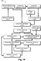
- Fig. 14 is a schematic block diagram illustrating interaction of components of exemplary graphical user interfaces (GUIs) 1400 according to some embodiments of the invention.
- GUIs graphical user interfaces
- GUI 1400 includes a group definition module 1410 adapted to accept a user input defining groups and a data receiver 1424 operable to receive a plurality of individual measurement input datum indicative of status of a substrate (e.g. from probe 40).
- the user input comprises a start command and a stop command.
- the group definition module includes a single button and a first press of the button indicates "begin assigning measurement input datum to a group" and a second click of the button indicates "last measurement input datum received was the end of a group".
- each click of the button after the first click indicates both an end of a preceding group and a beginning of a subsequent group.
- the button is positioned on probe 40.
- the user input comprises a name.
- the name can be selected from a menu (e.g. using a physical interface such as a scroll wheel, mouse or joystick) or entered manually by the user (e.g. using a keyboard or via a voice command).
- the name is indicative of a general location on the substrate.
- group names are according to a commonly used convention among medical practitioners: Medial (M), Lateral (L), Posterior/Deep (D), Anterior/Superficial (SF), Inferior (I) and Superior (S).
- multiple groups may be assigned to a same general location (e.g. S1, S2 or M1, M2 and M3).
- an interior surface of a body cavity serves as the substrate.
- data collected from the cavity is used by append "C” or "CAV” to group names of the commonly used convention described above.
- data is collected from an excised tissue and a cavity resulting from the excision in a single procedure.
- group numbers are used in place of names.
- groups are successively numbered in their collection order.
- names are presented to a user in nested menus.
- a user selects a group name from a list of names, optional names descriptive of regions.
- the user enters names without using a list, for example by using keyboard 26 or buttons 43 on probe 40 the user may name region 210 'XL'.
- the user may store the name 'XL' in a 'language' database for example at database storage unit 48.
- groups are named by pressing control buttons 43 and 44, or the keyboard 26 and/or by a voice operating system or machine and/or by using a touch screen and/or a virtual touch screen (e.g., by relating movements and gestures of the surgeon hands for operations on the screen).
- the user input defining groups and individual measurement input datum are processed by a grouping module 1430 configured to assign each of said individual measurement input datum to one of said groups to produce grouped data 1450 for output via an output module 1440.
- GUI 1400 includes a registration module 1460.
- registration module 1460 registers grouped data 1450 onto a substrate model 1452. Registration can be based upon general positional information (e.g. as indicated by a group name) and/or on position coordinates for one or more points in a group.
- Substrate model 1452 can be, for example, a geometric solid representation of the substrate (e.g. a cube, sphere, cylinder, tube or polyhedral solid), a space filling model of the substrate (e.g. a model based upon general characteristics of an anatomic feature or organ being examined) or an image of the substrate produced using any known imaging technology.
- registration to an image can be to a previously acquired image.
- individual datum indicative of status of said substrate are linked to position coordinates.
- the position coordinates are defined relative to the substrate.
- One exemplary way to accomplish this is to use a position sensor 1420 to generate position coordinates 1422 to be transmitted to data receiver 1424 together with individual measurement input datum from probe 40.
- position sensor 1420 is mounted on probe 40.
- Fig. 2A is a schematic representation of an exemplary output 200 of grouped data 1450 from GUI 1400.
- Output 200 can be displayed, for example, on display screen 24 and/or indicator 1, e.g. the LCD and/or stored in a memory of processor 50 and/or written to a machine readable media in read/write drive 27.
- output 200 displays information in a way designed to assist a user in making a diagnosis and/or planning a surgical response.
- Depicted exemplary output 200 includes groups of measurements or results 210, 220, 230, 240 and 250.
- each group corresponds to a region on the substrate.
- Groups may include one or more measurements or results and different groups can include different numbers of measurements/results.
- region 210 includes five measurements outputs, e.g. measurements 211, 212, 213, 214 and 215, while region 250 includes two measurements outputs 251 and 252.
- a single measurement relates to a single point on a substrate (e.g. a mass of excised tissue) and a group of measurements relates to an area or general location on the substrate where all the single measurements in the group were performed.
- a substrate e.g. a mass of excised tissue
- a user may examine an area 210' on substrate 260.
- the area 210' may be displayed in output 200 as group 210.
- the measurement output of each examined point in area 210' e.g. points 211', 212', 213', 214' and 215', may displayed, respectively, in region 210 for example as bars 211, 212, 213, 214 and 215 of Fig. 2A .
- Correlation between group 210 and area 210' is optionally provided by a descriptive title 216 or group name (e.g. L for lateral).
- each group is automatically named or numbered.
- the first region which was examined e.g. region 210 is numbered "One" and the following examined region is automatically numbered "Two".
- the user may insert a title (e.g. name or number) to each region, for example according to the location of the region in the examined substance, or according to the number of examination.
- a single measurement may be related to a single point on a substrate, such as a tissue, which was measured or characterized by a single sensor.
- the sensor is one of a group of sensors provided in an array on operative portion 42 of probe 40.
- a single measurement may be related to a plurality of points on a substrate measured by individual sensors belonging to a group of sensors provided in an array on operative portion 42 of probe 40.
- the single measure is an arithmetic mean or median of a range of measurements.
- an indication of variability is also provided.
- the group or array is optionally operated in concert. Operation in concert refers to concurrent or sequential measurements performed by individual sensors in the group/array as a result of a single operation input or command.
- use of groups or arrays of sensors contributes to an increase in accuracy and/or reliability of collected data without extending data collection time.
- a surgeon may attach the probe 40 to the area 210' on substance 260.
- operative portion 42 of probe 40 includes an array of sensors
- each point in area 210' may be presented as a single datum indicative all measurements from all sensors in the array or as a series of data outputs (one output for each sensor in the array).
- one or more measurement outputs of area 210' may be displayed on the information screen 200 using for example the display screen 24 or the indicator 1, e.g. the LCD.
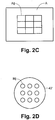
- Fig. 2C depicts an exemplary matrix A of outputs of a sensor array 42' ( Fig. 2D ).
- a matrix A is presented for each of examined points 211', 212', 213', 214' and 215' in area 210'.
- individual measurements are displayed concurrently with each index Aij in matrix A representing respectively an output from a single measurement by the corresponding sensor Bij of sensor array 42'.
- measurements from sensor array 42' are condensed into a single datum (e.g. by averaging) for each of examined points 211', 212', 213', 214' and 215' in area 210'.
- a data group (e.g. 210) includes multiple measurement outputs of Matrix A resulting from multiple operations of array 42' at multiple locations.
- the user may characterize a first substrate area (e.g. 211') using probe 40 with a sensor array 42' and a second substrate area (e.g. 214' or adjacent to the first area) by moving the senor array.
- measurement outputs 211 of the first substrate area and 214 of the second substrate area are in the form of matrix A
- the group presentation 210 is a sequence of matrices A.
- measurement outputs of the first substrate area and the second substrate area may be displayed as a single group (e.g. "M") or as separate groups (e.g. M1 and M2).
- M1 and M2 separate groups
- several probes including matrices are operated in parallel.
- use of matrices reduces data collection time and/or contributes to an increase in meaningfulness of grouped data.
- a single measurement output can be binary (e.g. yes/no or malignant/clear), discrete (e.g. on a scale with numbered units, optionally represented by symbols that increase in size incrementally) or continuous (e.g. a temperature, a conductivity, a color selected from a spectrum)
- a measurement output level or percentage of, for example a cancerous or non-cancerous substance e.g. a substrate tissue
- a cancerous or non-cancerous substance e.g. a substrate tissue
- digitally e.g. no/yes or red/green
- the cancerous or non-cancerous level or percentage may be indicated according to a bar length, or color and/or position with respect to a baseline
- a circle which is filled proportionally, as a combination of digital result and a bar, and only as a level result, e.g. including only the cancerous level without a yes or no indication.
- a faulty measurement e.g. faulty sensor signal, mechanical failure of the probe is indicated on the GUI, e.g. designated by an empty box and/or by a dedicated color and/or an error message.
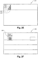
- Fig. 2E depicts an additional exemplary display screen 201 with bars 280 and 290 with lengths represent a cancerous percentage, (50% and 90% respectively) measured during a single measurement.
- individual measurement datum and/or group names are stored in system 100 (e.g. in control station 20 or in database storage unit 48 of probe 40).
- each measurement datum acquired by probe 40 is summarized by a transient audio indication.
- a beep may be used to indicate "normal” and a buzz may be used to indicate "abnormal" substrate status.
- a sequence of beeps may be used to indicate a faulty measurement
- a status of grouping module 1430 may be indicated by audio signals. For example delivery of a "start" signal from group definition module 1410 can produce a single click which indicates that subsequently acquired individual datum will be grouped together and delivery of a "stop" signal from group definition module 1410 can produce a double click which indicates an end to grouping.
- each measurement datum acquired by probe 40 is summarized by a transient visual indication.
- a transient visual indication For example, using the light sources 45 and 46 (e.g. red LED indicates abnormal measurement, green LED indicates normal measurement, yellow LED indicates a faulty measurement).
- Fig. 2F depicts an additional exemplary display screen 203 featuring exemplary output of a summary statistic 292 (e.g. average) for grouped data 1450.
- Summary statistic 292 can be presented instead of, or in addition to, individual bars representing status indicative data from individual locations.
- Types of summary statistic 292 include, but are not limited to mean average, mode, median, standard error of the mean (SEM) and standard deviation (SD).
- SEM standard error of the mean
- SD standard deviation
- two or more summary statistics are displayed concurrently (e.g. mean and SD or median, mean and SEM).
- a total measurement output 292 for each region may be displayed separately. The total measurement output 292 represents the total of all the measurements performed in the region.
- summary statistic 292 indicates a number of datum in the group with a value exceeding a predefined threshold, a peak or an integral of all measurements in the group.
- summary statistic 292 is presented during data acquisition and is updated as new data is added to the group.
- summary statistic 292 is presented when data acquisition ends and the group is closed.
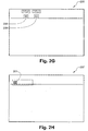
- Fig. 2G depicts an additional exemplary display screen 205 showing measurements outputs 298 and 299 including an alpha numeric measurement indication.
- Fig. 2H depicts concurrent display 291 of data from two different sensor types as described in detail hereinbelow.
- output of grouped data 1450 comprises individual datum arranged in groups and/or at least one statistic summarizing the individual datum in each of the groups.
- grouped data 1450 is stored in a memory module 1470.
- data receiver 1424 is adapted to receive individual measurement input datum concurrently from an array of probes. Alternatively or additionally, data receiver 1424 is adapted to receive individual measurement input datum concurrently from sensors of different types.
- user input is provided at before and/or during and/or after receipt of said plurality of individual measurement input datum by data receiver 1424.
- system 100 includes an apparatus for analysis of a substrate.
- the apparatus includes probe 40 operable to produce a plurality of individual signal datum indicative of substrate status.
- probe 40 is activated by contacting an operative portion 42 with a portion of the substrate and/or by operation of one or more control inputs 43.
- the apparatus includes group definition module 1410 ( Fig. 14 ) adapted to accept a user input defining groups and grouping module 1430 configured to receive said signal datum indicative of substrate status and assign each of said individual datum to one of said groups to produce grouped data 1450 and an output module 1440 adapted to output grouped data 1450.
- output module 1440 includes a display (e.g. 1 and/or 24) and/or memory (e.g. 27 or 50) and/or printer (not depicted).
- components such as group definition module 1410 and/or grouping module 1430 and/or output module 1440 are provided on probe 40.
- apparatus 100 includes one or more user input mechanism(s) on probe 40.
- buttons 43 on probe 40 function as user input mechanisms.
- apparatus 100 includes at least one indicator on probe 40 (e.g. LEDs 45 and 46). These indicators function as part of output module 1440.
- probe 40 measures dielectric and/or electromagnetic properties or other properties of said substrate as described hereinabove. Probes capable of measuring dielectric and/or electromagnetic properties or other properties have been described and one of ordinary skill in the art will be capable of adapting them for use in the context of the invention.
- probe 40 is manually operable (e.g. by button press and/or by contact with substrate).
- a plurality of individual datum indicative of substrate status (e.g. 211, 212, 213, 214 and 215) is correlated to manually selected locations on the substrate (211', 212', 213', 214' and 215'; See Figs. 2A and 2B ).
- the apparatus comprises a registration module 1460.
- registration module 1460 registers the grouped data onto a model of the substrate.
- the model can be a solid representation of the substrate (e.g. a cube, sphere, dodecahedron or cylinder) and/or a space filling model of the substrate and/or an image of the substrate.
- user input is indicative of a location on said substrate.
- group names entered via group definition module can be used to indicate which face of a cube grouped 1450 should be displayed upon.
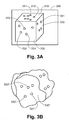
- Fig. 3A shows an exemplary output 300 of grouped data registered onto a three dimensional model.
- the substrate is represented as a cube. Faces 310, 320 and 330 of the cube are visible.
- a user optionally selects an automatic region selection mode display. For example the user may measure substrate characteristics at points on different regions of the substrate (e.g. [311, 312] and [321] and [331,332 and 333]) where the square brackets indicate group designations supplied by the user via group definition module 1410.
- registration module 1460 applies grouped data 1450 to substrate model 1452 to produce an output of the type depicted in Fig. 3A .
- substrate model 1452 is in the form of a cube, where each surface of the cube corresponds to a region of the cube according to the according to the M/L/D/SF/I/S nomenclature system described above.
- substrate model 1452 e.g. sphere, dodecahedron, tube or cylinder.
- a spherical model can employ names based on longitude and/or latitude.
- a tubular or cylindrical model can employ names based on z (e.g. top, top-center, center, center- bottom, and bottom) and angle in plane perpendicular to z.
- names can correspond to enumeration of faces in a predetermined order (e.g. 12 in the case of a dodecahedron), which may further be refined if the polyhedron has a specific symmetry (e.g. in the case of 6 face polyhedron: a cube, a box, a pyramid; each enable a more specialized enumeration)
- Fig. 3B shows an irregularly shaped substrate with a surface 330' corresponding to face 330 of the cube model of Fig. 3A .
- Locations 331', 332' and 333' indicate sites of measurements 331, 332 and 333 respectively.
- display 300 can include a model 1452 in the form of medical image data.
- Medical image date can include any imaging data, including image data types mentioned hereinabove.
- the image data may is pre-acquired or acquired concurrent with acquisition of individual datum indicative of substrate status.
- individual datum indicative of substrate status belonging to a same group are displayed registered on substrate model 1452 with a sign (e.g. group indicator) or form (e.g. color) to aid the user in identifying which points belong to groups indicative of which substrate regions.
- a sign e.g. group indicator
- form e.g. color
- individual datum indicative of substrate status of all points in a first region may have a first sign or symbol such as a star and/or color such as orange
- individual datum indicative of substrate status of all points which relate to a second region may include a second symbol such as a circle and/or a second color such as black.
- the M/L/D/SF/I/S nomenclature is linked to specific symbols and/or colors.
- the letters M/L/D/SF/I/S are used as symbols for the corresponding faces of the cube.
- colors are assigned to the six faces of the M/L/D/SF/I/S system (e.g. M-red, L-orange, D- yellow, SF- green, I- blue, S-violet).
- each displayed individual datum indicative of substrate status includes data relating to substrate status using different formats as described in detail hereinabove.
- summary statistics 292 as described hereinabove are displayed on each face.
- the summary statistics 292 summarize a singe group or all groups belonging to a particular face.
- summary statistic is color coded or marked with a symbol as described above for individual datum.
- individual datum indicative of substrate status belonging to a same group and/or residing on a same face are connected by a connector.
- the connector is as a surface area connector enclosing all individual datum belonging to the group.
- the connector is added automatically, for example by registration module 1460 and/or grouping module 1430.
- the connector can be, for example, a graphical indication of the relation between points.
- the graphical indication can include one or more of a line connecting the individual datum locations, a counter enclosing all the individual datum locations or a geometric shape contacting the individual datum locations.
- the connector is dynamic, and is updated as additional points belonging to the group are added. Updating can be fully automatic or in response to an update command.
- individual datum indicative of substrate status are linked to position coordinates. Exemplary means of acquiring position coordinates are described hereinbelow.
- operative portion 42 of probe 40 includes a plurality of sub-probes arranged in a spatial array as described above with reference to Figs. 2C and 2D .
- the sub-probes are collectively operable by a single probe activation signal.
- contact with the substrate serves as a probe activation signal.
- output of a group of sensors arranged in an array is used to provide a local summary of substrate status.
- probe 40 is operable in at least two modalities. For example, concurrent sensing and detection of electric impedance (EI) and magnetic resonance (MR) properties can be performed by operative portion 42 of probe 40.
- EI electric impedance
- MR magnetic resonance
- sensors for two or more modalities are integrated into one sensing head.
- different sensing modalities are combined to produce a third "hybrid" modality.
- concurrent measurement of EI properties of a specific region of the substrate and measurement of MR properties of the same substrate region produces a hybrid mode indicative of induced change in EI properties due to MR absorption of the incident electromagnetic radiation pulse.
- Fig. 15 is a simplified flow diagram of an exemplary method 1500 of analyzing a substrate.
- Depicted exemplary method 1500 includes selecting 1510 a plurality of locations on a substrate collecting 1520 a datum indicative of substrate status at each location and grouping 1530 the data into groups defined by a user.
- selecting 1510 is at least partially based upon visual inspection 1512 of the substrate by the user.
- datum indicative of substrate status reflect an evaluation 1522 of dielectric properties and/or electromagnetic properties of the substrate at each selected location.
- output 1540 of the groups contributes to an ability of the user to make a decision.
- the decision relates to diagnosis and/or surgery.
- output 1540 can be to a digital display (e.g. LCD or CRT screen) and/or printer and/or memory.
- the output can optionally include one or more additional features described below. Additional features can aid the user in making the decision.
- grouping 1530 is followed by computation 1550 of one or more summary statistics as described hereinabove.
- the summary statistic is output 1540 in addition to, or as an indication of, group data.
- method 1500 includes mapping 1560 groups onto a representation of the substrate.
- mapping 1560 is based upon definition 1570 of position coordinates for each location (as explained hereinbelow) and/or on user defined groups indicative of location 1532 (as explained hereinabove).
- mapping 1560 can be onto any representation of the substrate including but not limited to a polygonal solid representation of the substrate, a space filling model of the substrate and an image of the substrate.
- a substrate analysis system of the general type depicted in Fig. 1 as system 100 is modified with a position co-ordinate measurement module for determining position coordinates of the locations on the substrate.
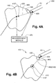
- Figs. 4A and 4B depict an exemplary measuring sub-system 400.
- Depicted exemplary measurement sub-system 400 employs a marker 410 in the substrate.
- marker 410 has been implanted during a previous procure, such as image guided biopsy.
- Marker 410 can be passive or active.
- Passive markers 410 can include, for example, a magnet or ultrasound reflector.
- embodiments of the invention which include a passive marker 410 can include an active location detector 435 on probe 40 (e.g. a signal transducer).
- Active markers 410 can include, for example, a radiofrequency RF or ultrasound (US) transducer.
- embodiments of the invention which include an active marker 410 can include a passive marker 435 on probe 40.
- marker 410 is placed at or near a geometric center of substrate 420 (e.g. a tumor or excised tissue mass) indicated as 410'. It is often convenient to define 410' as an origin (0, 0, 0) for a three dimensional coordinate system defining locations on substrate 420.
- probe 40 includes an active sensor 435 adapted to measure a distance 460 and a direction, e.g. a relative vector (X,Y,Z) 440 between location 445 at which a substrate indicative datum is acquired and marker 410.
- active sensor 435 adapted to measure a distance 460 and a direction, e.g. a relative vector (X,Y,Z) 440 between location 445 at which a substrate indicative datum is acquired and marker 410.
- Fig. 4A depicts another embodiment of the invention in which positions of marker 410 in substrate 420 and marker 435 on probe 40 are each determined by a measurement module which determines a distance and direction 460 between measurement location 445 and center 410'.
- the probe 40 may include a structure, configured for receiving and holding a tissue specimen, wherein the tissue specimen includes tissue positional references and positional references, associated with the structure, for fixing the orientation of the tissue specimen, when held by the probe, so as to reflect the tissue specimen positional references.
- tissue specimen includes tissue positional references and positional references, associated with the structure, for fixing the orientation of the tissue specimen, when held by the probe, so as to reflect the tissue specimen positional references.
- Such structure may be similar to various embodiments described, for example, in international publication number WO 2006/092797 , entitled “Device And Method For Transporting And Handling Tissue", assigned to the common assignee of the present application and hereby incorporated by reference.
- system 100 includes a substrate position indicator 410 positioned at substrate 420 and a probe 40 operable to evaluate substrate status and output status indicative datum at individual points (e.g. 445) and measurement module 470 configured to determine a relative position of position indicator 410 and probe 40.
- a controller e.g. controller 22 coordinates operation of probe 40 and measurement module 470 so that said relative position is determined for each of said individual points.
- a decrease in time difference between measurement of substrate status and of probe position contributes to an increase in accuracy of determined position for each substrate status measurement.
- the signal originates from probe 40 (e.g. from sensor 435) and is received at position indicator 410.
- the signal originates from position indicator 410 and is received at probe 40 (e.g. at sensor 435).
- measurement module 470 includes a position sensor adapted to determine a first position 445 of probe 40 (using marker 435) and a second position 410' indicating substrate location (using marker 410 to indicate (0,0,0)). According to these embodiments of the invention, measurement module 470 determines a relative position of marker 410 and marker 435 by comparing said first and second positions.
- Measurement module is located external with respect to a patient body and/or with respect to substrate 420.
- system 100 includes an imaging module adapted to produce an image depicting said probe and said position indicator and measurement module 470 determines a relative position of probe 40 and substrate center 410' relative to image data.
- the image data indicates markers 410 and/or 435.
- data indicative of substrate status is presented registered on a three dimensional representation of the substrate generated from the image data.
- probe 40 comprises a cutting tool.
- the cutting tool is mounted at or near operative portion 42 and/or sensor 435 so that position and/or substrate status information for location 445 is relevant to the cutting tool.
- output module 1440 outputs relative position of probe 40 together with status indicative datum for each of individual points 445.
- this contributes to an ability of registration module 1460 to register individual points 445 and/or grouped data 1450 on substrate model 1452.
- system 100 includes a procedure planning module 1480.
- Procedure planning module 1480 is adapted to analyze said output from said output module and/or registration module 1460 and calculate a path.
- the calculated path optionally serves as a cutting path and/or a guide for delivery of implantable devices and/or medications.
- implantable devices include, but are not limited to brachytherapy seeds and stents.
- the path includes one or more location designations for performance of procedures (e.g. cutting and/or implantation, injection of medicine and/or ablation).
- planning module 1480 considers registration of status indicative data at multiple points 445 on substrate 420 registered to medical image data of any type when calculating a path.
- planning module 1480 is adapted to accept additional user input 1482 pertaining to a planned path (e.g. a cutting path) based upon output of said registration module.
- procedure planning module 1480 considers grouped data 1450 as well as outputs from output module 1440 and/or registration module 1460 inputs and outputs.
- planning module 1480 receives inputs from the user via an additional GUI.
- the additional GUI includes a three dimensional graphical interface.
- planning module 1480 outputs a proposed path or other plan related information graphically, optionally as a three dimensional model.
- graphic output of the proposed path or other plan related information is presented overlaid and/or registered with a medical image.
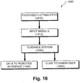
- Fig. 16 depicts a surgical supervision system 1600.
- system 1600 aids in performance of surgery.
- Depicted exemplary system 1600 includes an input module 1612 adapted to receive a proposed path (e.g. cutting) 1610 from a procedure planning module.
- the procedure planning module is optionally a planning module 1480 as described above.
- Depicted exemplary system 1600 also includes a guidance system 1620 adapted to output guidance instructions to guide a surgical tool along said path.
- the instructions are provided in a data format 1630 suitable for use by a robotic interface and/or as cues 1640 suitable for use by a human user.
- display 300 can include an image overlay such as probe reading (e.g. a binary reading per point) with a window showing an image such as a 3D image of the substrate and/or a characterized an anatomic feature.
- the reading optionally enables guiding of and/or instructions for guiding a surgical tool to a specific region shown on display 300.
- probe readings are registered on the image.
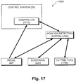
- FIG. 17 is a schematic representation of one possible configuration of a guidance system 1620 as shown in Fig. 16 in greater detail.
- position detection system 1720 determines positions of substrate 420 and probe 40 using any technology known in the art.
- position detection system 1720 may rely upon markers implanted in substrate 420 and/or installed on probe 40 as described hereinabove.
- a cutting tool 1730 is provided as a separate unit from probe 40. According to these exemplary embodiments, position detection system separately determines a position of cutting tool 1730.
- cutting tool 1730 is provided as part of probe 40. According to these exemplary embodiments, position detection system concurrently determines the position of cutting tool and of probe 40.
- position detection system 1720 is in communication with a controller 1710, optionally integrated in control station 20.
- position detection system 1720 determines a relative position of probe 40 and/or cutting tool 1730 with respect to substrate 420.
- controller 1710 determines a relative position of probe 40 and/or cutting tool 1730 with respect to substrate 420 based upon position data received from position detection system 1720.
- controller 1710 also receives data indicative of substrate status as described hereinabove from probe 40. In some exemplary embodiments of the invention, controller 1710 integrates and/or correlates this data with corresponding position data for probe 40 to produce position correlated substrate status data. Optionally, controller 1710 constructs a status map from the position correlated substrate status data.
- controller 1710 compares the status map to the proposed path provided by input module 1612 ( Fig. 16 ). As probe 40 and/or cutting tool 1730 are moved, the status map and/or proposed path can be updated by controller 1710 to produce a current status map and/or a current path.
- controller 1710 formulates data 1630 for the robotic interface and/or cues 1640 for the human user based upon the current status map and/or the current path.
- exemplary embodiments of the invention reside in substrate probe 40.
- probe 40 is adapted to interact with system 100.
- Depicted exemplary substrate probe 40 includes a data acquisition module adapted to engage a substrate at a user selected point, analyze the substrate and produce a datum indicative of substrate status at said point.
- the data acquisition module is depicted schematically as operative portion 42.
- operative portion 42 includes a pair of electrodes in communication with a cavity and a vacuum source configured to draw a portion of a substrate into the cavity so that it contacts the electrodes.
- Depicted exemplary substrate probe 40 includes a user input device in the form of buttons 43 (three are depicted).
- the user input device is configured to group individual datum into groups of data.
- buttons 43 are provided.
- a single button serves as a user input device.
- buttons 43 are replaced by other mechanical, electronic or electromechanical input hardware (e.g. slider, rheostat, scroll wheel, microswitch).
- Depicted exemplary substrate probe 40 includes a signal conduit 5 adapted to relay electrical and/or optical signals and a lumen adapted to relay a negative pressure from an external vacuum source to the data acquisition module (e.g. operative portion 42).
- the lumen adapted to relay negative pressure resides in conduit 5.
- the lumen adapted to relay negative pressure is provided separately.
- Depicted exemplary substrate probe 40 includes a connector to an external data analysis component.
- this connector resides in conduit 5 and/or relies upon a wireless link.
- probe 40 is provided as a sterile medical device.
- probe 40 is provided in packaging configured to insure sterility until probe 40 is opened in an operating theater. Considerations in sterile packaging configuration are known to those of ordinary skill in the art of medical diagnostics and will be easily applied to embodiments of the invention.
- probe 40 comprises a user perceptible indicator.
- the indicator provides a visible and/or audible indication as described above.
- probe 40 In order to make apparent some advantages of probe 40, an exemplary use scenario is described in detail.
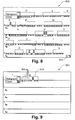
- Fig. 5 is an exemplary simplified schematic flow-chart of a method 500 for measuring and displaying measurements outputs of a substrate.
- a determination of whether group measurement mode is required is made.
- a group mode is entered and a group/region name is entered or selected from a predefined list at 530. Entry can optionally be by a user (e.g. physician) or automatic as described hereinbelow in relation to Fig. 6 .
- one or more measurements which belong to the chosen group are performed, for example by probe 40.
- Storage can be, for example in control station 20 or in database storage unit 48 of probe 40.
- Display is optionally on display screen 24 or indicator 1.
- Fig. 6 is schematic diagram of an exemplary embodiment of front panel buttons 600 of console 20.
- operations done using the console front panel buttons 600 may alternatively be performed using button(s) 43 of probe 40.
- a double click on button 43 may initiate group mode process.
- a consecutive number starting for example with '1', is automatically presented in response to the double click.
- letter can be employed in a predefined order, for example according to M/L/D/SF/I/S convention.
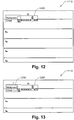
- Fig. 12 depicts an exemplary display screen 1110 in which a second double click optionally closes a group mode, for example depicted first group 1200 (M).
- a second double click optionally closes a group mode, for example depicted first group 1200 (M).
- closing of a group closes a frame around the group as shown.
- Fig. 13 depicts an exemplary display screen 1112 in which an additional double click opens a second group 1210 (1) as shown.
- opening of a group causes a new frame to appear.
- the new frame is open on its left side as depicted.
- button 610 on panel 600 can be operated in an analogous manner to perform the same functions.
- Fig. 9 depicts an exemplary display screen 900 in which a "closed" group 910 (optionally representative of a region [e.g. M] on the substrate) including one or more measurements outputs 920 is illustrated.
- a measurement may also be initiated immediately, without entering a group mode.
- a long single press on the button 43 of probe 40 or button 620 on console 600 enters a group name mode.
- a menu of names is accessed (e.g. Medial - M, Lateral-L, Posterior (Deep)-D, Anterior (Superficial)-SF, Inferior-I, Superior-S, # - number that was automatically chosen for the group, CAV - to enter into relevant sides of the cavity).
- buttons 1102 may be provided in the control station 20 or probe 40.
- buttons are labeled with group names corresponding to region names as indicated.
- a similar set of names can be presented as a menu on a display screen.
- the group to be presented after a first press will be the next group that follows after the previous chosen group.
- a sign '#' may represent a group number which was automatically chosen by the system.
- the region or group name is approved (e.g. by a long press on button 43 or 620)
- the user may scroll between a list of regions (e.g. using button 650).
- a long press on button 43 or 620 approves a specific region as indicated by group name.
- entering group name mode for next group will start immediately with a list of regions options.
- a group's name may be approved by a long press on probe's button 43 or by pressing on button 620 on console's front panel 600.
- a group name may be colored, for example in red until it is approved by long button press on button 43 or 620. Once approved, the color of the group's name may be switched for example to yellow. In some embodiments measurements can not be taken until group is approved.
- a group name may be changed, even after it was approved, as long as the group was not closed. In some embodiments after a group was closed, the group name can not be changed. In some embodiments, actions can not be done before approving a group name. For example a message, such as an audio or digital message, will pop up on the screen in cases such as: group name was not approved, and/or after two seconds from choosing a name.
- a user may double press on button 43 or 610 on the console.
- the user may open a second group by double clicking button 43.
- the measurements can be performed immediately without choosing group name.
- a group name was not chosen it could be chosen at any time, for example as long as the group mode is active.
- a group name may be chosen more than one time.
- Fig. 8 illustrates an exemplary embodiment of a display screen 800 in which a output of a next measurement "pushes" previous measurements to a next row which is not visible on the screen, and a scroll indicator 810 is activated, as shown in Fig. 8 .
- the user may use button 43 or button 640 or the joystick for scrolling up or down the measurements.
- the "next" measurement output of the same region output or the next single measurement output may be presented in the "next" row.
- the next measurement output 1100 of region output 1200 is displayed in the next row 1300.
- An error massage may be displayed on probe 40 or on display screen 24.
- an indication of an error message may be activated using for example an audio indicator machine.
- a group may be selected before the measurements related to that group have been initiated. Alternatively, the group may be selected after some of the measurements which related to the group have been acquired or alternatively the group may be selected after all the measurements related to the group have been acquired.
- Fig. 7 depicts an exemplary output screen 700 in which current measurements are highlighted. Highlighting can be, for example, by changing characteristics of background and/or a frame indicating a current group and/or characteristics of a current measurement (e.g. bar width or color).
- data from a session is saved in storage unit 48 for further analysis.
- session data may also be exported and transmitted to an external device/computer or to an external memory device such as a removable memory e.g. a DiskonKey or other small and portable memory device.
- Session data recorded or saved may be used, for example, in additional procedures, such as pathology procedures, related to the examined tissue. Session data which was recorded or saved may be also used in additional procedures, such as additional surgical or diagnostic procedures on a same subject.
- Some exemplary embodiments of the invention are of an apparatus 1400 for analysis of a substrate including a probe 40 as described hereinabove, a modeling module 1454 adapted to produce a three dimensional model of the substrate and a registration module 1460 adapted to indicate the specified locations on the model.
- the modeling module relies upon defined position coordinates 1422 and/or substrate models 1452 (e.g. predefined geometric models or realistic modes indicative of actual substrate shape or models based on medical image data).
- the apparatus includes an output module adapted to present an indication of substrate status at each of the specified locations on the model.
- presentation is as an overlay.
- the model is a 3D model which can be manipulated (e.g. rotated or inverted) during viewing.
- apparatus 1400 is adapted to accept a user input specifying a position of said locations (e.g. user provides coordinates 1422).
- apparatus 1400 is adapted to determine a position of said locations.
- apparatus 1400 employs position sensors 1420 adapted to determine a position of said locations.
- output of registered data from registration module 1460 is to one or more of a graphic display, a printer and a memory.
- components and/or actions ascribed to exemplary embodiments of the invention and depicted as a single unit may be divided into subunits.
- components and/or actions ascribed to exemplary embodiments of the invention and depicted as sub-units/individual actions may be combined into a single unit/action with the described/depicted function.
Claims (11)
- Computerisiertes System (20) zum Überwachen von Messungen an einem Gewebeabschnitt, wobei das System umfasst:(i) einen Prozessor (50), der dazu eingerichtet ist, mit einer Messsonde (40) zu kommunizieren, um Eingabedaten zu empfangen und zu verarbeiten, welche Benutzereingaben, die Gruppen definieren, sowie Daten umfassen, die indikativ für gemessene Gewebeeigenschaften an Orten innerhalb eines Gewebebereichs sind;(ii) eine Anzeigevorrichtung (24), die eine grafische Benutzerschnittstelle (GUI) (1400) anzeigt und mit dem Prozessor verbunden ist;wobei der Prozessor umfasst:(a) ein Gruppendefinitionsmodul (1410), das dazu eingerichtet und betreibbar ist, die Benutzereingabedaten entgegenzunehmen, welche Gruppen einschließlich eines Starts und eines Endes jeder Gruppe gemäß einer Benutzergruppierung ausgewählter Orte zu Gruppen definieren, welche sich auf die Orte auf dem Gewebeabschnitt beziehen, die während einer Messungssitzung zu messen sind;(b) einen Datenempfänger, der dazu eingerichtet und betreibbar ist, von der Messsonde die Daten zu empfangen, die für mehrere einzelne Messungseingabedaten von einer oder mehreren Messungen an dem Gewebeabschnitt indikativ sind, die während einer Messungssitzung gemessen werden;(c) ein Gruppierungsmodul, das mit dem Gruppendefinitionsmodul und dem Datenempfänger operativ verbunden ist, wobei das Gruppierungsmodul dazu eingerichtet und betreibbar ist, die entgegengenommenen Benutzereingabedaten zu verarbeiten, welche den Start und das Ende jeder Gruppe gemäß der Benutzergruppierung der ausgewählten zu messenden Orte umfassen, und die mehreren einzelnen Messungseingabedaten zu verarbeiten, die zwischen dem Start und dem Ende der Gruppe gemessen werden, und jedes der einzelnen Messungseingabedaten einer der Gruppen zuzuweisen, um gruppierte Daten zu produzieren, welche die mehreren während jeder Messungssitzung gemessenen einzelnen Messungseingabedaten mit den entsprechenden benutzerausgewählten Orten verknüpfen; und(d) ein Ausgabemodul, das mit dem Gruppierungsmodul operativ verbunden ist und dazu eingerichtet und betreibbar ist, die gruppierten Daten für jede Messungssitzung in der GUI auszugeben, um Daten über die Gewebeeigenschaften an den benutzerausgewählten Orten, die während der Messungssitzungen gemessen werden, auf der Anzeigevorrichtung anzuzeigen.
- System nach Anspruch 1, ferner umfassend ein Registrierungsmodul.
- System nach Anspruch 2, wobei das Registrierungsmodul dazu eingerichtet und betreibbar ist, die gruppierten Daten auf ein unter Folgendem ausgewähltes Element zu registrieren: eine körperliche Darstellung des Gewebeabschnitts, ein raumerfüllendes Modell des Gewebeabschnitts, ein Bild des Gewebeabschnitts und ein dreidimensionales Bild des Gewebeabschnitts.
- System nach einem der Ansprüche 1 bis 3, wobei die einzelnen Messungseingabedaten den Ortsdaten zugeordnet sind, welche Positionskoordinaten umfassen.
- System nach Anspruch 4, wobei die Positionskoordinaten relativ zu dem Gewebeabschnitt definiert sind.
- System nach einem der Ansprüche 1 bis 5, wobei die Ausgabe der gruppierten Daten mindestens eine zusammenfassende Statistik von jeder der Gruppen umfasst.
- System nach einem der Ansprüche 1 bis 6, ferner umfassend:
eine Messsonde, die dazu eingerichtet und betreibbar ist, Messungssitzungen an dem Gewebeabschnitt auszuführen und Eingabedaten zu produzieren, welche Benutzereingaben und gemessene Daten umfassen, die für Gewebeeigenschaften an Messorten auf dem Gewebeabschnitt indikativ sind. - System nach Anspruch 7, wobei die Messsonde einen oder mehreren Sensoren zum Messen von dielektrischen Eigenschaften und/oder elektromagnetischen Eigenschaften des Gewebeabschnitts umfasst.
- System nach Anspruch 7 oder 8, wobei die Messsonde mehrere Sub-Sonden umfasst, die in einem räumlichen Feld angeordnet sind, wobei die Sub-Sonden kollektiv durch ein einzelnes Sondenaktivierungssignal betreibbar sind.
- System nach einem der Ansprüche 7 bis 9, wobei die Sonde in mindestens zwei Messwerterfassungs-/Charakterisierungs-Modalitäten betreibbar ist.
- Verfahren, implementiert durch das computerisierte System nach einem der Ansprüche 1 bis 10, zum Überwachen von Messungen an einem Gewebeabschnitt und zum Anzeigen von während Messungssitzungen gesammelten gemessenen Daten in einer grafischen Benutzeroberfläche (GUI) auf einer Computeranzeige, wobei das Verfahren umfasst:Empfangen von Eingaben von einem Benutzer, wobei die Benutzereingaben Gruppen einschließlich eines Starts und eines Endes jeder Gruppe gemäß einer Benutzergruppierung ausgewählter Orte zu Gruppen definieren, welche sich auf die Orte auf dem Gewebeabschnitt beziehen, die während einer Messungssitzung zu messen sind;Empfangen mehrerer einzelner Messungseingabedaten von einer Messsonde, die für eine oder mehrere Messungen an dem Gewebeabschnitt indikativ sind, die während jeder Messungssitzung gemessen werden;Verarbeiten der Benutzereingaben, die Gruppen einschließlich des Starts und des Endes für jede Gruppe definieren, und Verarbeiten der mehreren einzelnen Messungseingabedaten, die zwischen dem Start und dem Ende für jede Gruppe empfangen werden, und Zuweisen der jeweiligen mehreren einzelnen Messungseingabedaten an die ausgewählten Orte, und Produzieren gruppierter Daten; undErzeugen von Ausgabedaten, wobei die Ausgabedaten die die gruppierten Daten für jede Messungssitzung umfassen und dazu eingerichtet sind, in der GUI auf der Computeranzeige angezeigt zu werden, umfassend Daten über die Gewebeeigenschaften an den ausgewählten Orten, die während der Messungssitzungen gemessen werden.
Priority Applications (1)
| Application Number | Priority Date | Filing Date | Title |
|---|---|---|---|
| EP11188221.3A EP2418599B1 (de) | 2006-12-12 | 2007-12-12 | Grafische benutzeroberfläche, verfahren und vorrichtung zur datenpräsentation |
Applications Claiming Priority (3)
| Application Number | Priority Date | Filing Date | Title |
|---|---|---|---|
| US87428006P | 2006-12-12 | 2006-12-12 | |
| US91482207P | 2007-04-30 | 2007-04-30 | |
| PCT/IL2007/001539 WO2008072238A2 (en) | 2006-12-12 | 2007-12-12 | Graphical user interfaces (gui), methods and apparatus for data presentation |
Related Child Applications (2)
| Application Number | Title | Priority Date | Filing Date |
|---|---|---|---|
| EP11188221.3A Division EP2418599B1 (de) | 2006-12-12 | 2007-12-12 | Grafische benutzeroberfläche, verfahren und vorrichtung zur datenpräsentation |
| EP11188221.3A Division-Into EP2418599B1 (de) | 2006-12-12 | 2007-12-12 | Grafische benutzeroberfläche, verfahren und vorrichtung zur datenpräsentation |
Publications (2)
| Publication Number | Publication Date |
|---|---|
| EP2118801A2 EP2118801A2 (de) | 2009-11-18 |
| EP2118801B1 true EP2118801B1 (de) | 2019-02-20 |
Family
ID=39205171
Family Applications (2)
| Application Number | Title | Priority Date | Filing Date |
|---|---|---|---|
| EP11188221.3A Active EP2418599B1 (de) | 2006-12-12 | 2007-12-12 | Grafische benutzeroberfläche, verfahren und vorrichtung zur datenpräsentation |
| EP07849566.0A Active EP2118801B1 (de) | 2006-12-12 | 2007-12-12 | Verfahren und vorrichtung zur bereitstellung einer graphischen benutzerschnittstelle zur datenerfassung und datendarstellung |
Family Applications Before (1)
| Application Number | Title | Priority Date | Filing Date |
|---|---|---|---|
| EP11188221.3A Active EP2418599B1 (de) | 2006-12-12 | 2007-12-12 | Grafische benutzeroberfläche, verfahren und vorrichtung zur datenpräsentation |
Country Status (5)
| Country | Link |
|---|---|
| EP (2) | EP2418599B1 (de) |
| JP (1) | JP5620108B2 (de) |
| CN (1) | CN101606158B (de) |
| ES (2) | ES2725779T3 (de) |
| WO (1) | WO2008072238A2 (de) |
Families Citing this family (6)
| Publication number | Priority date | Publication date | Assignee | Title |
|---|---|---|---|---|
| ES2627041T3 (es) | 2008-06-11 | 2017-07-26 | Dune Medical Devices Ltd. | Registro doble |
| US9217739B2 (en) | 2011-06-02 | 2015-12-22 | Dune Medical Devices Ltd. | Tissue sampling for pathological study |
| JP6022671B2 (ja) * | 2012-03-29 | 2016-11-09 | スパイレーション インコーポレイテッド ディー ビー エイ オリンパス レスピラトリー アメリカ | 肺組織の同定および処置のための装置、方法、およびシステム |
| JP6434959B2 (ja) * | 2013-04-11 | 2018-12-05 | フィリップス メディカル システムズ テクノロジーズ リミテッド | ユーザが画像データを研究するのを可能にすること |
| CN104346506B (zh) * | 2013-07-31 | 2018-11-30 | Ge医疗系统环球技术有限公司 | 一种对医学影像图像进行处理和输出的方法及装置 |
| JP2021533896A (ja) | 2018-08-16 | 2021-12-09 | ディロン メディカル テクノロジーズ リミテッドDilon Medical Technologies LTD. | 組織属性表現システム及び方法 |
Family Cites Families (34)
| Publication number | Priority date | Publication date | Assignee | Title |
|---|---|---|---|---|
| US4458694A (en) | 1977-11-02 | 1984-07-10 | Yeda Research & Development Co., Ltd. | Apparatus and method for detection of tumors in tissue |
| IL53286A (en) | 1977-11-02 | 1980-01-31 | Yeda Res & Dev | Apparatus and method for detection of tumors in tissue |
| JPS5772627A (en) | 1980-10-21 | 1982-05-07 | Tokyo Shibaura Electric Co | Apparatus for detecting abnormal cell |
| CA1196691A (en) | 1982-01-12 | 1985-11-12 | Bradley Fry | Reconstruction system and methods for impedance imaging |
| US4617939A (en) | 1982-04-30 | 1986-10-21 | The University Of Sheffield | Tomography |
| IL91193A (en) | 1989-08-02 | 1996-01-19 | Yeda Res & Dev | Tumor detection system |
| US5615132A (en) | 1994-01-21 | 1997-03-25 | Crossbow Technology, Inc. | Method and apparatus for determining position and orientation of a moveable object using accelerometers |
| EP0694282B1 (de) | 1994-07-01 | 2004-01-02 | Interstitial, LLC | Nachweis und Darstellung von Brustkrebs durch elektromagnetische Millimeterwellen |
| US5704355A (en) | 1994-07-01 | 1998-01-06 | Bridges; Jack E. | Non-invasive system for breast cancer detection |
| US6560480B1 (en) | 1994-10-24 | 2003-05-06 | Transscan Medical Ltd. | Localization of anomalies in tissue and guidance of invasive tools based on impedance imaging |
| EP0864075A1 (de) * | 1995-11-28 | 1998-09-16 | DORNIER MEDICAL SYSTEMS, Inc. | Verfahren und system zur nichtinvasiven temperaturabbildung von gewebe |
| CN1095354C (zh) * | 1996-06-04 | 2002-12-04 | 浙江大学 | 用于心血管疾病的无损定量诊断系统的使用方法 |
| US6109270A (en) | 1997-02-04 | 2000-08-29 | The United States Of America As Represented By The Administrator Of The National Aeronautics And Space Administration | Multimodality instrument for tissue characterization |
| JP3460495B2 (ja) * | 1997-03-03 | 2003-10-27 | 日本電信電話株式会社 | 電子画像表示方法および電子画像表示装置 |
| GB2324450A (en) * | 1997-04-19 | 1998-10-21 | Ibm | Graphical user interface |
| EP1100373B1 (de) | 1998-08-02 | 2008-09-03 | Super Dimension Ltd. | Intrakorporales navigationssystem für medizinische anwendungen |
| CN1122499C (zh) * | 1999-06-17 | 2003-10-01 | 曾金铃 | 疾病诊断预测系统 |
| JP2001170036A (ja) * | 1999-12-16 | 2001-06-26 | Hitachi Medical Corp | 医用x線診断装置 |
| US6834122B2 (en) * | 2000-01-22 | 2004-12-21 | Kairos Scientific, Inc. | Visualization and processing of multidimensional data using prefiltering and sorting criteria |
| US6409684B1 (en) * | 2000-04-19 | 2002-06-25 | Peter J. Wilk | Medical diagnostic device with multiple sensors on a flexible substrate and associated methodology |
| JP2002366649A (ja) * | 2001-05-23 | 2002-12-20 | National Cardiovascular Center | 遺伝性疾患解析のための情報・検体集積分配ネットワークシステム |
| US7505811B2 (en) | 2001-11-19 | 2009-03-17 | Dune Medical Devices Ltd. | Method and apparatus for examining tissue for predefined target cells, particularly cancerous cells, and a probe useful in such method and apparatus |
| US20070255169A1 (en) | 2001-11-19 | 2007-11-01 | Dune Medical Devices Ltd. | Clean margin assessment tool |
| US8116845B2 (en) | 2005-08-04 | 2012-02-14 | Dune Medical Devices Ltd. | Tissue-characterization probe with effective sensor-to-tissue contact |
| US6813515B2 (en) | 2002-01-04 | 2004-11-02 | Dune Medical Devices Ltd. | Method and system for examining tissue according to the dielectric properties thereof |
| US7809425B2 (en) * | 2003-07-24 | 2010-10-05 | Dune Medical Devices Ltd. | Method and apparatus for examining a substance, particularly tissue, to characterize its type |
| US7720532B2 (en) * | 2004-03-23 | 2010-05-18 | Dune Medical Ltd. | Clean margin assessment tool |
| US8019411B2 (en) | 2002-01-04 | 2011-09-13 | Dune Medical Devices Ltd. | Probes, systems, and methods for examining tissue according to the dielectric properties thereof |
| US8721565B2 (en) | 2005-08-04 | 2014-05-13 | Dune Medical Devices Ltd. | Device for forming an effective sensor-to-tissue contact |
| CN100473336C (zh) | 2003-07-24 | 2009-04-01 | 沙丘医疗设备有限公司 | 用于检查特别是组织的物质以表征其类型的方法和设备 |
| JP2005251075A (ja) * | 2004-03-08 | 2005-09-15 | Fuji Photo Film Co Ltd | 医療用画像表示方法および装置 |
| US8449477B2 (en) | 2005-03-02 | 2013-05-28 | Dune Medical Devices Ltd. | Device and method for transporting and handling tissue |
| JP4693452B2 (ja) * | 2005-03-23 | 2011-06-01 | 株式会社東芝 | 画像管理システム及び画像管理装置 |
| JP4265798B2 (ja) * | 2005-05-13 | 2009-05-20 | 学校法人慶應義塾 | 画像データ管理方法、画像データ管理装置、画像データ管理システム、プログラム、及び記録媒体 |
-
2007
- 2007-12-12 WO PCT/IL2007/001539 patent/WO2008072238A2/en active Application Filing
- 2007-12-12 EP EP11188221.3A patent/EP2418599B1/de active Active
- 2007-12-12 EP EP07849566.0A patent/EP2118801B1/de active Active
- 2007-12-12 JP JP2009540969A patent/JP5620108B2/ja active Active
- 2007-12-12 ES ES07849566T patent/ES2725779T3/es active Active
- 2007-12-12 CN CN200780051197.XA patent/CN101606158B/zh active Active
- 2007-12-12 ES ES11188221T patent/ES2748925T3/es active Active
Non-Patent Citations (1)
| Title |
|---|
| None * |
Also Published As
| Publication number | Publication date |
|---|---|
| JP2010512221A (ja) | 2010-04-22 |
| WO2008072238A8 (en) | 2009-08-13 |
| EP2118801A2 (de) | 2009-11-18 |
| WO2008072238A2 (en) | 2008-06-19 |
| CN101606158A (zh) | 2009-12-16 |
| ES2748925T3 (es) | 2020-03-18 |
| CN101606158B (zh) | 2014-04-02 |
| EP2418599A3 (de) | 2014-01-22 |
| ES2725779T3 (es) | 2019-09-27 |
| EP2418599B1 (de) | 2019-07-10 |
| JP5620108B2 (ja) | 2014-11-05 |
| EP2418599A2 (de) | 2012-02-15 |
Similar Documents
| Publication | Publication Date | Title |
|---|---|---|
| US11179053B2 (en) | Graphical user interfaces (GUI), methods and apparatus for data presentation | |
| EP1913875B1 (de) | Ultraschallsystem zur Fusion eines Ultraschallbildes und eines externen medizinischen Bildes | |
| CN101437455B (zh) | 具有有效的传感器到组织接触的组织表征探头 | |
| CN106999052B (zh) | 交互式心脏测试数据和相关联的设备、系统和方法 | |
| US9655595B2 (en) | System, method and device for prostate diagnosis and intervention | |
| US8172753B2 (en) | Systems and methods for visualization of an ultrasound probe relative to an object | |
| CN109199598B (zh) | 用于实时三维(3d)心脏成像中玻璃态视图的系统和方法 | |
| US20080119697A1 (en) | Bidirectional communication interface | |
| EP2118801B1 (de) | Verfahren und vorrichtung zur bereitstellung einer graphischen benutzerschnittstelle zur datenerfassung und datendarstellung | |
| US20110208052A1 (en) | Breast ultrasound annotation user interface | |
| CN103271718A (zh) | 具有有效的传感器到组织接触的组织表征探头 | |
| CN108231180B (zh) | 医学图像显示设备及其方法 | |
| US20230103969A1 (en) | Systems and methods for correlating regions of interest in multiple imaging modalities | |
| CN103974664A (zh) | 具有多个超声换能器的检查系统 | |
| JP7460355B2 (ja) | 医療ユーザインターフェース | |
| JP7410148B2 (ja) | 肺疾患の迅速診断用の経皮カテーテルシステムおよび方法 | |
| JP2023032238A (ja) | 医用画像表示装置 | |
| CN117651537A (zh) | 用于无线定位集成的系统和方法 | |
| CN116138876A (zh) | 手术视野展示方法、装置、设备和介质 | |
| CN116236280A (zh) | 一种基于多模态图像融合的介入治疗引导方法及系统 |
Legal Events
| Date | Code | Title | Description |
|---|---|---|---|
| PUAI | Public reference made under article 153(3) epc to a published international application that has entered the european phase |
Free format text: ORIGINAL CODE: 0009012 |
|
| 17P | Request for examination filed |
Effective date: 20090707 |
|
| AK | Designated contracting states |
Kind code of ref document: A2 Designated state(s): AT BE BG CH CY CZ DE DK EE ES FI FR GB GR HU IE IS IT LI LT LU LV MC MT NL PL PT RO SE SI SK TR |
|
| 17Q | First examination report despatched |
Effective date: 20091109 |
|
| DAX | Request for extension of the european patent (deleted) | ||
| GRAP | Despatch of communication of intention to grant a patent |
Free format text: ORIGINAL CODE: EPIDOSNIGR1 |
|
| STAA | Information on the status of an ep patent application or granted ep patent |
Free format text: STATUS: GRANT OF PATENT IS INTENDED |
|
| RIC1 | Information provided on ipc code assigned before grant |
Ipc: G16H 10/20 20180101ALI20180718BHEP Ipc: G06F 19/00 20060101AFI20180718BHEP |
|
| INTG | Intention to grant announced |
Effective date: 20180820 |
|
| GRAS | Grant fee paid |
Free format text: ORIGINAL CODE: EPIDOSNIGR3 |
|
| GRAA | (expected) grant |
Free format text: ORIGINAL CODE: 0009210 |
|
| STAA | Information on the status of an ep patent application or granted ep patent |
Free format text: STATUS: THE PATENT HAS BEEN GRANTED |
|
| AK | Designated contracting states |
Kind code of ref document: B1 Designated state(s): AT BE BG CH CY CZ DE DK EE ES FI FR GB GR HU IE IS IT LI LT LU LV MC MT NL PL PT RO SE SI SK TR |
|
| REG | Reference to a national code |
Ref country code: GB Ref legal event code: FG4D |
|
| REG | Reference to a national code |
Ref country code: CH Ref legal event code: EP |
|
| REG | Reference to a national code |
Ref country code: DE Ref legal event code: R096 Ref document number: 602007057649 Country of ref document: DE |
|
| REG | Reference to a national code |
Ref country code: AT Ref legal event code: REF Ref document number: 1099139 Country of ref document: AT Kind code of ref document: T Effective date: 20190315 |
|
| REG | Reference to a national code |
Ref country code: IE Ref legal event code: FG4D |
|
| REG | Reference to a national code |
Ref country code: NL Ref legal event code: FP |
|
| REG | Reference to a national code |
Ref country code: LT Ref legal event code: MG4D |
|
| PG25 | Lapsed in a contracting state [announced via postgrant information from national office to epo] |
Ref country code: LT Free format text: LAPSE BECAUSE OF FAILURE TO SUBMIT A TRANSLATION OF THE DESCRIPTION OR TO PAY THE FEE WITHIN THE PRESCRIBED TIME-LIMIT Effective date: 20190220 Ref country code: SE Free format text: LAPSE BECAUSE OF FAILURE TO SUBMIT A TRANSLATION OF THE DESCRIPTION OR TO PAY THE FEE WITHIN THE PRESCRIBED TIME-LIMIT Effective date: 20190220 Ref country code: PT Free format text: LAPSE BECAUSE OF FAILURE TO SUBMIT A TRANSLATION OF THE DESCRIPTION OR TO PAY THE FEE WITHIN THE PRESCRIBED TIME-LIMIT Effective date: 20190620 Ref country code: FI Free format text: LAPSE BECAUSE OF FAILURE TO SUBMIT A TRANSLATION OF THE DESCRIPTION OR TO PAY THE FEE WITHIN THE PRESCRIBED TIME-LIMIT Effective date: 20190220 |
|
| PG25 | Lapsed in a contracting state [announced via postgrant information from national office to epo] |
Ref country code: IS Free format text: LAPSE BECAUSE OF FAILURE TO SUBMIT A TRANSLATION OF THE DESCRIPTION OR TO PAY THE FEE WITHIN THE PRESCRIBED TIME-LIMIT Effective date: 20190620 Ref country code: BG Free format text: LAPSE BECAUSE OF FAILURE TO SUBMIT A TRANSLATION OF THE DESCRIPTION OR TO PAY THE FEE WITHIN THE PRESCRIBED TIME-LIMIT Effective date: 20190520 Ref country code: LV Free format text: LAPSE BECAUSE OF FAILURE TO SUBMIT A TRANSLATION OF THE DESCRIPTION OR TO PAY THE FEE WITHIN THE PRESCRIBED TIME-LIMIT Effective date: 20190220 Ref country code: GR Free format text: LAPSE BECAUSE OF FAILURE TO SUBMIT A TRANSLATION OF THE DESCRIPTION OR TO PAY THE FEE WITHIN THE PRESCRIBED TIME-LIMIT Effective date: 20190521 |
|
| REG | Reference to a national code |
Ref country code: AT Ref legal event code: MK05 Ref document number: 1099139 Country of ref document: AT Kind code of ref document: T Effective date: 20190220 |
|
| REG | Reference to a national code |
Ref country code: ES Ref legal event code: FG2A Ref document number: 2725779 Country of ref document: ES Kind code of ref document: T3 Effective date: 20190927 |
|
| PG25 | Lapsed in a contracting state [announced via postgrant information from national office to epo] |
Ref country code: DK Free format text: LAPSE BECAUSE OF FAILURE TO SUBMIT A TRANSLATION OF THE DESCRIPTION OR TO PAY THE FEE WITHIN THE PRESCRIBED TIME-LIMIT Effective date: 20190220 Ref country code: SK Free format text: LAPSE BECAUSE OF FAILURE TO SUBMIT A TRANSLATION OF THE DESCRIPTION OR TO PAY THE FEE WITHIN THE PRESCRIBED TIME-LIMIT Effective date: 20190220 Ref country code: EE Free format text: LAPSE BECAUSE OF FAILURE TO SUBMIT A TRANSLATION OF THE DESCRIPTION OR TO PAY THE FEE WITHIN THE PRESCRIBED TIME-LIMIT Effective date: 20190220 Ref country code: RO Free format text: LAPSE BECAUSE OF FAILURE TO SUBMIT A TRANSLATION OF THE DESCRIPTION OR TO PAY THE FEE WITHIN THE PRESCRIBED TIME-LIMIT Effective date: 20190220 Ref country code: CZ Free format text: LAPSE BECAUSE OF FAILURE TO SUBMIT A TRANSLATION OF THE DESCRIPTION OR TO PAY THE FEE WITHIN THE PRESCRIBED TIME-LIMIT Effective date: 20190220 |
|
| REG | Reference to a national code |
Ref country code: DE Ref legal event code: R097 Ref document number: 602007057649 Country of ref document: DE |
|
| PG25 | Lapsed in a contracting state [announced via postgrant information from national office to epo] |
Ref country code: PL Free format text: LAPSE BECAUSE OF FAILURE TO SUBMIT A TRANSLATION OF THE DESCRIPTION OR TO PAY THE FEE WITHIN THE PRESCRIBED TIME-LIMIT Effective date: 20190220 |
|
| PLBE | No opposition filed within time limit |
Free format text: ORIGINAL CODE: 0009261 |
|
| STAA | Information on the status of an ep patent application or granted ep patent |
Free format text: STATUS: NO OPPOSITION FILED WITHIN TIME LIMIT |
|
| PG25 | Lapsed in a contracting state [announced via postgrant information from national office to epo] |
Ref country code: AT Free format text: LAPSE BECAUSE OF FAILURE TO SUBMIT A TRANSLATION OF THE DESCRIPTION OR TO PAY THE FEE WITHIN THE PRESCRIBED TIME-LIMIT Effective date: 20190220 |
|
| 26N | No opposition filed |
Effective date: 20191121 |
|
| PG25 | Lapsed in a contracting state [announced via postgrant information from national office to epo] |
Ref country code: SI Free format text: LAPSE BECAUSE OF FAILURE TO SUBMIT A TRANSLATION OF THE DESCRIPTION OR TO PAY THE FEE WITHIN THE PRESCRIBED TIME-LIMIT Effective date: 20190220 |
|
| PG25 | Lapsed in a contracting state [announced via postgrant information from national office to epo] |
Ref country code: TR Free format text: LAPSE BECAUSE OF FAILURE TO SUBMIT A TRANSLATION OF THE DESCRIPTION OR TO PAY THE FEE WITHIN THE PRESCRIBED TIME-LIMIT Effective date: 20190220 |
|
| REG | Reference to a national code |
Ref country code: CH Ref legal event code: PL |
|
| REG | Reference to a national code |
Ref country code: BE Ref legal event code: MM Effective date: 20191231 |
|
| PG25 | Lapsed in a contracting state [announced via postgrant information from national office to epo] |
Ref country code: MC Free format text: LAPSE BECAUSE OF FAILURE TO SUBMIT A TRANSLATION OF THE DESCRIPTION OR TO PAY THE FEE WITHIN THE PRESCRIBED TIME-LIMIT Effective date: 20190220 |
|
| PG25 | Lapsed in a contracting state [announced via postgrant information from national office to epo] |
Ref country code: IE Free format text: LAPSE BECAUSE OF NON-PAYMENT OF DUE FEES Effective date: 20191212 Ref country code: LU Free format text: LAPSE BECAUSE OF NON-PAYMENT OF DUE FEES Effective date: 20191212 |
|
| PG25 | Lapsed in a contracting state [announced via postgrant information from national office to epo] |
Ref country code: LI Free format text: LAPSE BECAUSE OF NON-PAYMENT OF DUE FEES Effective date: 20191231 Ref country code: BE Free format text: LAPSE BECAUSE OF NON-PAYMENT OF DUE FEES Effective date: 20191231 Ref country code: CH Free format text: LAPSE BECAUSE OF NON-PAYMENT OF DUE FEES Effective date: 20191231 |
|
| PG25 | Lapsed in a contracting state [announced via postgrant information from national office to epo] |
Ref country code: CY Free format text: LAPSE BECAUSE OF FAILURE TO SUBMIT A TRANSLATION OF THE DESCRIPTION OR TO PAY THE FEE WITHIN THE PRESCRIBED TIME-LIMIT Effective date: 20190220 |
|
| PG25 | Lapsed in a contracting state [announced via postgrant information from national office to epo] |
Ref country code: MT Free format text: LAPSE BECAUSE OF FAILURE TO SUBMIT A TRANSLATION OF THE DESCRIPTION OR TO PAY THE FEE WITHIN THE PRESCRIBED TIME-LIMIT Effective date: 20190220 Ref country code: HU Free format text: LAPSE BECAUSE OF FAILURE TO SUBMIT A TRANSLATION OF THE DESCRIPTION OR TO PAY THE FEE WITHIN THE PRESCRIBED TIME-LIMIT; INVALID AB INITIO Effective date: 20071212 |
|
| PGFP | Annual fee paid to national office [announced via postgrant information from national office to epo] |
Ref country code: ES Payment date: 20230120 Year of fee payment: 16 |
|
| PGFP | Annual fee paid to national office [announced via postgrant information from national office to epo] |
Ref country code: DE Payment date: 20221227 Year of fee payment: 16 |
|
| PGFP | Annual fee paid to national office [announced via postgrant information from national office to epo] |
Ref country code: GB Payment date: 20231219 Year of fee payment: 17 |
|
| PGFP | Annual fee paid to national office [announced via postgrant information from national office to epo] |
Ref country code: NL Payment date: 20231226 Year of fee payment: 17 Ref country code: IT Payment date: 20231221 Year of fee payment: 17 Ref country code: FR Payment date: 20231226 Year of fee payment: 17 |
|
| PGFP | Annual fee paid to national office [announced via postgrant information from national office to epo] |
Ref country code: ES Payment date: 20240118 Year of fee payment: 17 |