EP2118638B2 - Verbrennungsgasanalyse - Google Patents
Verbrennungsgasanalyse Download PDFInfo
- Publication number
- EP2118638B2 EP2118638B2 EP08725953.7A EP08725953A EP2118638B2 EP 2118638 B2 EP2118638 B2 EP 2118638B2 EP 08725953 A EP08725953 A EP 08725953A EP 2118638 B2 EP2118638 B2 EP 2118638B2
- Authority
- EP
- European Patent Office
- Prior art keywords
- combustion gas
- combustion
- oxygen
- concentration
- carbon monoxide
- Prior art date
- Legal status (The legal status is an assumption and is not a legal conclusion. Google has not performed a legal analysis and makes no representation as to the accuracy of the status listed.)
- Active
Links
Images


Classifications
-
- G—PHYSICS
- G01—MEASURING; TESTING
- G01N—INVESTIGATING OR ANALYSING MATERIALS BY DETERMINING THEIR CHEMICAL OR PHYSICAL PROPERTIES
- G01N21/00—Investigating or analysing materials by the use of optical means, i.e. using sub-millimetre waves, infrared, visible or ultraviolet light
- G01N21/17—Systems in which incident light is modified in accordance with the properties of the material investigated
- G01N21/25—Colour; Spectral properties, i.e. comparison of effect of material on the light at two or more different wavelengths or wavelength bands
- G01N21/31—Investigating relative effect of material at wavelengths characteristic of specific elements or molecules, e.g. atomic absorption spectrometry
- G01N21/39—Investigating relative effect of material at wavelengths characteristic of specific elements or molecules, e.g. atomic absorption spectrometry using tunable lasers
-
- F—MECHANICAL ENGINEERING; LIGHTING; HEATING; WEAPONS; BLASTING
- F23—COMBUSTION APPARATUS; COMBUSTION PROCESSES
- F23N—REGULATING OR CONTROLLING COMBUSTION
- F23N5/00—Systems for controlling combustion
- F23N5/003—Systems for controlling combustion using detectors sensitive to combustion gas properties
-
- F—MECHANICAL ENGINEERING; LIGHTING; HEATING; WEAPONS; BLASTING
- F23—COMBUSTION APPARATUS; COMBUSTION PROCESSES
- F23N—REGULATING OR CONTROLLING COMBUSTION
- F23N5/00—Systems for controlling combustion
- F23N5/02—Systems for controlling combustion using devices responsive to thermal changes or to thermal expansion of a medium
- F23N5/08—Systems for controlling combustion using devices responsive to thermal changes or to thermal expansion of a medium using light-sensitive elements
- F23N5/082—Systems for controlling combustion using devices responsive to thermal changes or to thermal expansion of a medium using light-sensitive elements using electronic means
-
- G—PHYSICS
- G01—MEASURING; TESTING
- G01N—INVESTIGATING OR ANALYSING MATERIALS BY DETERMINING THEIR CHEMICAL OR PHYSICAL PROPERTIES
- G01N21/00—Investigating or analysing materials by the use of optical means, i.e. using sub-millimetre waves, infrared, visible or ultraviolet light
- G01N21/17—Systems in which incident light is modified in accordance with the properties of the material investigated
- G01N21/25—Colour; Spectral properties, i.e. comparison of effect of material on the light at two or more different wavelengths or wavelength bands
- G01N21/31—Investigating relative effect of material at wavelengths characteristic of specific elements or molecules, e.g. atomic absorption spectrometry
- G01N21/35—Investigating relative effect of material at wavelengths characteristic of specific elements or molecules, e.g. atomic absorption spectrometry using infrared light
- G01N21/3504—Investigating relative effect of material at wavelengths characteristic of specific elements or molecules, e.g. atomic absorption spectrometry using infrared light for analysing gases, e.g. multi-gas analysis
-
- G—PHYSICS
- G01—MEASURING; TESTING
- G01N—INVESTIGATING OR ANALYSING MATERIALS BY DETERMINING THEIR CHEMICAL OR PHYSICAL PROPERTIES
- G01N21/00—Investigating or analysing materials by the use of optical means, i.e. using sub-millimetre waves, infrared, visible or ultraviolet light
- G01N21/17—Systems in which incident light is modified in accordance with the properties of the material investigated
- G01N21/25—Colour; Spectral properties, i.e. comparison of effect of material on the light at two or more different wavelengths or wavelength bands
- G01N21/31—Investigating relative effect of material at wavelengths characteristic of specific elements or molecules, e.g. atomic absorption spectrometry
- G01N21/314—Investigating relative effect of material at wavelengths characteristic of specific elements or molecules, e.g. atomic absorption spectrometry with comparison of measurements at specific and non-specific wavelengths
- G01N2021/3144—Investigating relative effect of material at wavelengths characteristic of specific elements or molecules, e.g. atomic absorption spectrometry with comparison of measurements at specific and non-specific wavelengths for oxymetry
-
- G—PHYSICS
- G01—MEASURING; TESTING
- G01N—INVESTIGATING OR ANALYSING MATERIALS BY DETERMINING THEIR CHEMICAL OR PHYSICAL PROPERTIES
- G01N21/00—Investigating or analysing materials by the use of optical means, i.e. using sub-millimetre waves, infrared, visible or ultraviolet light
- G01N21/17—Systems in which incident light is modified in accordance with the properties of the material investigated
- G01N21/25—Colour; Spectral properties, i.e. comparison of effect of material on the light at two or more different wavelengths or wavelength bands
- G01N21/31—Investigating relative effect of material at wavelengths characteristic of specific elements or molecules, e.g. atomic absorption spectrometry
- G01N21/35—Investigating relative effect of material at wavelengths characteristic of specific elements or molecules, e.g. atomic absorption spectrometry using infrared light
- G01N21/3504—Investigating relative effect of material at wavelengths characteristic of specific elements or molecules, e.g. atomic absorption spectrometry using infrared light for analysing gases, e.g. multi-gas analysis
- G01N2021/354—Hygrometry of gases
-
- G—PHYSICS
- G01—MEASURING; TESTING
- G01N—INVESTIGATING OR ANALYSING MATERIALS BY DETERMINING THEIR CHEMICAL OR PHYSICAL PROPERTIES
- G01N21/00—Investigating or analysing materials by the use of optical means, i.e. using sub-millimetre waves, infrared, visible or ultraviolet light
- G01N21/17—Systems in which incident light is modified in accordance with the properties of the material investigated
- G01N21/25—Colour; Spectral properties, i.e. comparison of effect of material on the light at two or more different wavelengths or wavelength bands
- G01N21/31—Investigating relative effect of material at wavelengths characteristic of specific elements or molecules, e.g. atomic absorption spectrometry
- G01N21/39—Investigating relative effect of material at wavelengths characteristic of specific elements or molecules, e.g. atomic absorption spectrometry using tunable lasers
- G01N2021/396—Type of laser source
- G01N2021/399—Diode laser
Definitions
- the instant invention is in the field of combustion gas analysis and more specifically the instant invention is in the field of tunable diode laser spectroscopic analysis of combustion gases.
- Tunable diode laser spectroscopic analysis of combustion gases is known and described in the prior art, for example, by: Lackner et al., Thermal Science, V.6, p13-27, 2002 ; Allen, Measurement Science and Technology, V.9, p545-562, 1998 ; Nikkary et al., Applied Optics, V.41(3), p446-452, 2002 ; Upschulte et al., Applied Optics, V.38(9), p1506-1512, 1999 ; Mihalcea et al., Measurement Science and Technology, V.9, p327-338, 1998 ; Webber et al., Proceedings of the Combustion Institute, V.28, p407-413, 2000 ; Ebert et al., Proceedings of the Combustion Institute, V.30, p16
- EAFs electric arc furnaces
- a near-infrared (IR) tunable diode laser (1.56 micron) performs in-situ off-gas analysis of gas temperature and carbon monoxide and water concentrations in the exhaust gas region above a laboratory burner.
- the applicable range of conditions includes temperatures from 1250 to 1650 K, CO concentration from 0 to 10 pct, and H2O concentration from 7 to 30 pct.
- the TDL source and the detector are placed either side of a flow of the exhaust gas and supply light to the measurement volume.
- a CO absorption line and H2O absorption line which are sufficiently close to permit rapid simultaneous measurement with a single laser source are selected.
- diode laser absorption spectroscopy is already known for measuring H2O, N02, CH4, CO, 02 i.e. carbon monoxide, water vapour and hydrocarbons.
- the instant invention is a solution to the above-stated problems for the simultaneous analysis of carbon monoxide, gaseous water and gaseous hydrocarbon in combustion gas by tunable diode laser spectroscopy.
- the sensitivity of analysis is improved by operating the tunable diode laser in a wavelength range of from 2 to 2.5 micrometers.
- Multivariate processing techniques for manipulating the spectral data allow the simultaneous determination of carbon monoxide, gaseous water and gaseous hydrocarbon even though only a single tunable diode laser is used. More specifically, the instant invention provides a method according to claim 1.
- the measurement of gas species in a combustion system is important for safe, environmentally responsible, and efficient operation. While not limited thereto, the instant invention has particular importance to hydrocarbon processing furnaces and heaters.
- the specific gas species and condition measurements used in this invention are, Oxygen (O 2 ), Carbon Monoxide (CO), Combustion Gas Temperature, Water (H 2 O) and hydrocarbons (C-H) such as methane (CH 4 ).
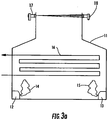
- a hydrocarbon processing heater or furnace 10 such as an ethylene cracker, a petroleum refinery heater, a petroleum refinery hydrocracker, a petroleum refinery fluidized catalytic cracker and an electrical power generation steam boiler.
- the heater or furnace 10 is comprised of an enclosure or wall 11, a pipe 16 carrying, for example, a stream of hydrocarbon to be heated, by the flames 14 and 15 from burners 12 and 13.
- Fig. 2 therein is shown a plot of concentration v. percent excess burner air for the relationship between key combustion parameters for the heater or furnace of Fig. 1 .
- the primary operational concerns addressed by the instant invention are, efficiency of the burners (optimum air/fuel ratio), emissions from the combustion system (CO, CO2, NOx, etc.), and safety monitoring (flame loss, fuel rich burner conditions, leak or rupture of the product tube).
- Combustion efficiency requirements can be generally summarized as optimizing the air/fuel ratio to the burners with the lowest amount of excess air in the combustion byproducts.
- Fuel feed to the burners is typically determined by the firing rate required for processing (amount of heat required). Air feed to the burners must be high enough to allow complete combustion without the production of excess emissions (CO, etc.) and unburnt fuel (hydrocarbons). Excess air will be heated by the flame, consuming some of the heat which then is not available for the primary purpose of the combustion system (such as cracking feedstock). Excess air to a burner will also generate NOx emissions.
- Figure 2 illustrates the relationship between efficiency, safety and emissions.
- Emissions requirements are determined by the operator or the governmental authority. In many cases an industrial plant or the individual furnace/heater has a limit on the amount of pollutants and greenhouse gases that can be emitted.
- Primary pollutants are carbon monoxide (CO), NOx (nitric oxide + nitrogen dioxide) and carbon dioxide (CO 2 ). In some cases the firing rate of the burners (production rate) can be limited by the need to remain below mandated emissions limits. Measurement of the pollutants, or the conditions required to generate the pollutants can be used to control and reduce emissions reduction.
- Safe operation of combustion systems requires that explosive mixtures are not present in the combustion system. These explosive mixtures can occur under three common conditions. First, if the burner(s) are not supplied with enough air, unburnt fuel will be present in the burner(s). This unburnt fuel can be ignited if excess air is then introduced into the system, from the burner air feed or from air leaks into the system. Second, if the burner(s) flame goes out (flameout, liftoff) the air/fuel feed to the burner will enter the combustion chamber, any subsequent ignition source can ignite this mixture. Third, if the furnace/heater is used for processing hydrocarbons, a leak in the product tube can introduce unburnt hydrocarbons to the combustion chamber. If excess air is present, along with an ignition source an explosion can occur. Measurement of the presence of the explosive mixture along with other conditions can both indicate the un-safe condition and the source of the safety breach.
- a tunable diode laser gas analysis system includes a laser module 37 containing the tunable diode laser.
- a control unit 31 contains the central processing unit programmed for signal processing (to be discussed below in greater detail) as well as the temperature and current control for the tunable diode laser and a user interface and display. Alignment plate 29 and adjustment rods 30 allow alignment of the laser beam 41.
- Dual process isolation windows 28 are mounted in a 10 cm (four inch) pipe flange 40.
- the space between the windows 28 is purged with approximately 25 Liters per minute of nitrogen at 69 KPa. (ten pounds per square inch) gauge pressure.
- the flange 40 is mounted through the wall of the furnace.
- the laser beam 41 is passed through the combustion gas and then through dual process isolation windows 33 to a near infrared light detector 38.
- the windows 33 are mounted in a 10 cm (four inch) pipe flange 39.
- the space between the windows 33 is purged with approximately 25 Liters per minute of nitrogen at 69 KPa. (ten pounds per square inch) gauge pressure.
- the flange 39 is mounted through the wall of the furnace.
- Alignment plate 34 and adjustment rods 35 allow alignment of the detector optics with the laser beam 41.
- Detector electronics 36 are in electrical communication with the control unit 31 by way of cable 37a.
- the control unit 31 is also in electrical communication (by way of electrical cables 38a) with a process control system 32 for controlling the furnace 10.
- the system shown in Fig. 4 is commercially available from Analytical Specialties of Houston, Texas.
- the system shown in Fig. 4 operates by measuring the amount of laser light at specific wavelengths, which light is absorbed (lost) as it travels through the combustion gas. Carbon monoxide, gaseous water and hydrocarbons each have a spectral absorption of infrared light that exhibits unique fine structure. The individual features of the spectra are seen at the high resolution of the tunable diode laser 37.
- Fig. 3b therein is shown a schematic drawing of the heater or furnace of Fig. 1 employing two tunable diode laser gas analysis systems 17, 18, 19 and 20, and a pair of zirconia oxygen sensors 21 and 22.
- the system shown in Fig. 3b is an example of the present disclosure.
- the oxygen measurement can be performed a number of ways. Two common methods are zirconia oxide probes, tunable diode laser (TDL) spectroscopy, or a combination of both. This application will include a description of a combination of zirconia oxide probes with tunable diode laser spectroscopy in relation to Fig.
- TDL tunable diode laser
- the TDL oxygen analyzer 19, 20 at a wavelength in the range of from 759 to 779 nanometers provides a path average oxygen concentration to avoid errors due to the uneven oxygen distribution across the firebox.
- Gas Temperature can be calculated and provided as an output from the analyzer.
- the zirconia oxygen probes provide a point measurement of oxygen which can be used to diagnose localized inefficiencies in multi-burner systems.
- CO measurement is also possible using a number of analysis methods such as, solid state sensors, non dispersive infrared and tunable diode laser.
- the preferred embodiment of this invention is the use of TDL spectroscopy to measure the CO in the combustion gas. With proper absorption line selection in the wavelength range of from 2 to 2.5 micrometers it is also possible to measure H 2 O and hydrocarbons (methane and others) with a single tunable diode laser system.
- TDL is an optical measurement.
- the measured gas absorbs the laser light at a specific wavelength.
- the amount of light absorbed is a function of gas concentration, pressure, temperature and optical path length.
- the process heater/furnace also has single or multiple burners 12 and 13, that are used to provide the heat for the thermal processing. These burners are supplied with air and fuel, both of which are controlled to provide the desired heat, control efficiency, reduce emissions and ensure safe operation.
- the gas species measurements may be used to meet the goals of maximum heat capacity, efficient operation (lowest burner fuel costs), safe operation (avoiding explosive mixtures in the furnace), and reducing emissions.
- the key operational parameter is minimizing excess air, while providing the desired heat, minimizing unburnt fuel, and staying within emissions limits.
- the gas measurements listed above may be used as follows. Oxygen and CO measurements will indicate the efficiency of the burner(s), minimum oxygen concentration without significant levels of CO can indicate optimum overall furnace fuel efficiency. The combination of path average and point source oxygen measurements can indicate localized burner efficiency if multiple burners are present in the system. Gas temperature measurement can indicate the amount of heat available for product processing. CO can also be used as a pre-cursor to fuel rich conditions where burner fuel (combustibles) is not burned and present in the combustion chamber.
- C-H measurement can be used to indicate the presence of unburnt fuel from the burners.
- H 2 O measurement can be used to calculate efficiency.
- a combination of oxygen and CO measurement can be used to predict or calculate the pollutant emissions such as CO 2 and NOx since both of these pollutants increase as air and fuel levels to the burners increase. For example NOx is produced from the nitrogen and oxygen present in the air supplied to the burner(s), increased excess air (above the minimum level required) will lead to increased NOx formation.
- the gas measurements may be used as follows. Oxygen levels will rise since oxygen present in the burner air feed is not being consumed by the combustion process. Gas temperature levels will fall rapidly upon the loss of the heat source (flame). Gas H 2 O levels will fall rapidly since they are produced as a combustion by product. Methane and other hydrocarbon levels will increase in large amounts. By providing and monitoring each of these gas measurements a loss of burner flame can be inferred.
- Hydrocarbon levels will increase in the combustion chamber as the product from the tube enters the combustion chamber. If steam is also present in the product tube, H 2 O levels will increase as the steam enters the combustion chamber. Oxygen levels, gas temperature and CO levels may also change under these conditions and potentially be used for diagnostics and control.
- H 2 O levels will increase as the steam enters the combustion chamber. Oxygen levels, gas temperature and CO levels may also change under these conditions and potentially be used for diagnostics and control.
- the preferred embodiment of this invention uses tunable diode laser spectrometer(s) to measure oxygen, carbon monoxide, hydrocarbons such as methane, water vapor and temperature. These measurements can be utilized in many combustion driven thermal processing systems, one example being refinery process heaters.
- TDL spectroscopy uses a tunable diode laser as the light source.
- This laser is typically controlled at a constant temperature to establish the course wavelength position, the laser is then modulated using a current ramp from the control electronics, modulation results in a wavelength scan over a repeated range (i.e. 760nm to 761nm for oxygen).
- the modulated laser light passes through beam shaping optics, and then a first process isolation window, through the gas being measured where if the gas being measured is present it absorbs a portion of the infrared light transmitted across the process, another process isolation window, to an appropriate light sensitive detector selected for the wavelength being used for measurement.
- the detector signal is sampled by an appropriate data acquisition system, the results are then processed by the analyzer digital central processing unit (CPU).
- CPU digital central processing unit
- One example of such a device is the TruePeak Tunable Diode Laser analyzer available from Analytical Specialties, Inc of Houston, Texas.
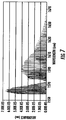
- Each of the gases used for measurement have a unique absorption of infrared light.
- this is the infrared absorption spectra for oxygen.
- a path average concentration basically counts the number of molecules of the gas being measured that are in the beam of laser light.
- a path average measurement versus a point source measurement is that all of the analyte is measured, point sensors only measure a small portion of the process, if the analyte is distributed throughout the process a point measurement may not be representative of the entire system.
- both a path average and one or more point source measurements may be desirable, for example to diagnose burner malfunctions. If path and point measurements are desired a combination of both types of measurements may be employed as shown in Figure 3b .
- Oxygen measurement can be made with this type of analytical device by selecting any suitable absorption peak shown in Figure 5 , from 759 to 779nm.
- oxygen absorption peak strength is strongly related to the gas temperature, if two lines are selected that have sufficiently different line strength vs. temperature, measuring both and comparing the line strength allows the inference of gas temperature.
- This same approach may be used with other analytes (moisture as an example), this embodiment uses the oxygen peaks for temperature measurement.
- An example of the present disclosure uses the CO peaks in the wavelength range of 2290 to 2580nm. Two specific examples will be outlined as they are particularly well suited for combustion analysis requirements at high temperatures. Measurement of CO close to the burners themselves has an advantage in that the CO levels are typically higher closest to the burners, making the measurement and control simpler. As the combustion gases travel further from the burner system they continue to react, this reaction results in lower CO levels further from the burner(s) at lower temperature zones. In addition the measurement response time is reduced.
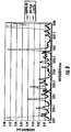
- Figure 8 shows HITRAN absorption spectra of CO, H 2 O and CH4 from 2324 to 2328nm.
- This wavelength region is one example where a single diode laser can be wavelength modulated to cover the absorption wavelengths for CO, H 2 O and multiple hydrocarbons, methane being the example used here.
- Figure 9 shows HITRAN absorption spectra of CO, H 2 O and CH4 from 2301.9 to 2302.4nm.
- This wavelength region is another example where a single diode laser can be wavelength modulated to cover the absorption wavelengths for CO, H 2 O and multiple hydrocarbons, methane being the example used here.
- Figure 10 shows absorption spectra, collected across a long path at 1100C, in approximately the same wavelength range as Figure 9 (2301.9 to 2302.4nm) wherein the plain curve relates to CO plus H 2 O while the triangle marked curve relates to H 2 O.
- Figure 9 2301.9 to 2302.4nm
- the background H2O absorption pattern is different than expected. This is primarily due to the fact that HITRAN was originally designed for atmospheric monitoring applications and it isn't very accurate for high temperature condition. Because of long path (20 meters), background H 2 O absorbance interference with CO absorbance is significant. Concentration prediction based on a simple peak height measurement or peak area integration is not possible (or at least very difficult) while maintaining measurement integrity.
- CLS classical least squares
- the signal processing is done by a digital computer, preferably a general purpose digital computer programmed to perform one of the following types of analysis of the signal(s) stored in the digital computer.
- CLS is a type of multivariate analysis which uses a mathematical model to predict concentration level of each component.
- Multivariate analysis includes classical least square (CLS), principal components regression (PCR) and partial least squares (PLS).
- CLS is probably the simplest. It requires calibration to get all the spectra of each component, and then build a mathematical model for future mixture measurement. Calibration is the process of constructing a mathematical model to relate the output of an instrument to properties of samples.
- Prediction is the process of using the model to predict properties of a sample given an instrument output.
- the absorbance at a given wavelength can be related to the concentration of an analyte.
- instrument responses from samples with known concentration levels are measured and a mathematical relationship is estimated which relates the instrument response to the concentration of a chemical component(s).
- This model may be used to predict the concentration of a chemical component in future samples using the measured instrument response(s) from those samples.
- Many instrumental responses can be considered, and a number of sample properties can be predicted.
- one response from an instrument is related to the concentration of a single chemical component. This is referred to as univariate calibration because only one instrument response is used per sample.
- Multivariate calibration is the process of relating multiple responses from an instrument to a property or properties of a sample.
- the samples could be, for example, a mixture of chemical components in a process stream, and the goal is to predict the concentration levels of the different chemical components in the stream from infrared measurements.
- the following specific wavelengths are specifically recommended when the combustion gas has a temperature of about 300°C: 2307.8; 2320.6; 2323.6; 2331.9; 2339.3; 2353.9; 2360.8; 2368.0; 2373.1; 2389.3; and 2401.0.
- the selection of the best wavelength is application dependent and determined by a reasonable degree of experimentation. Factors such as the desired sensitivity, the optical pathlength (furnace size) and combustion gas temperature are important variables.
- the instant invention comprises the monitoring of oxygen, temperature, carbon monoxide, water vapor and hydrocarbons in a single analytical system.
- the combination of these measurements along with an understanding of the process conditions that affect these gas measurements allows not only combustion efficiency optimization, emissions reduction and safety monitoring, but also allows the discrimination between conditions.
- One embodiment of this invention allows discrimination between air rich or fuel rich conditions along with discrimination between unsafe conditions such as product tube leaks and burner flame out.
- Another embodiment of this invention which includes additional point oxygen measurements allows localized diagnostics in multiple burner systems.
Landscapes
- Physics & Mathematics (AREA)
- Engineering & Computer Science (AREA)
- Chemical & Material Sciences (AREA)
- Spectroscopy & Molecular Physics (AREA)
- General Physics & Mathematics (AREA)
- Analytical Chemistry (AREA)
- Biochemistry (AREA)
- General Health & Medical Sciences (AREA)
- Life Sciences & Earth Sciences (AREA)
- Immunology (AREA)
- Pathology (AREA)
- Health & Medical Sciences (AREA)
- Combustion & Propulsion (AREA)
- Mechanical Engineering (AREA)
- General Engineering & Computer Science (AREA)
- Optics & Photonics (AREA)
- Investigating Or Analysing Materials By Optical Means (AREA)
Claims (6)
- Verfahren zum Überwachen und Steuern eines durch eine Verbrennung betriebenen Wärmeverarbeitungssystems, um Zielsetzungen hinsichtlich der Effizienz, Umweltsicherheit und Betriebssicherheit zu erzielen, wobei das durch eine Verbrennung betriebene Wärmeverarbeitungssystem ein Verbrennungsgas erzeugt, umfassend die Schritte: (i) Bestimmen der Konzentration von Sauerstoff in dem Verbrennungsgas, (ii) Bestimmen der Temperatur des Verbrennungsgases, und (iii) Bestimmen der Konzentration von Kohlenmonoxid, gasförmigem Wasser und gasförmigem Kohlenwasserstoff in einem Verbrennungsgas durch ein Verfahren unter Verwendung der Schritte: (a) Richten eines wellenlängenmodulierten Lichts von einem einzelnen abstimmbaren Diodenlaser (17) mit einer Wellenlänge im Bereich von 2 bis 2,5 Mikrometer durch das Verbrennungsgas auf einen Lichtdetektor (18), um ein Absorptionsprofil des Verbrennungsgases zu erzeugen, (b) Digitalisieren des Absorptionsprofils des Verbrennungsgases, (c) Speichern des digitalisierten Absorptionsprofils in einem digitalen Computer, (d) Verarbeiten des digitalisierten Absorptionsprofils in dem digitalen Computer, um eine Ausgabe aus dem Computer zu erzeugen, die die Konzentration von Kohlenmonoxid, gasförmigem Wasser und gasförmigem Kohlenwasserstoff in dem Verbrennungsgas angibt,
wobei die Konzentration von Sauerstoff in dem Verbrennungsgas und die Temperatur des Verbrennungsgases spektroskopisch bestimmt werden,
wobei die Temperatur durch Messen von zwei Sauerstoffabsorptionspeaks bestimmt wird,
wobei das durch eine Verbrennung betriebene Wärmeverarbeitungssystem eine Vielzahl von Kohlenwasserstoffbrennern und ein Prozessrohr einsetzt und wobei die Bestimmungen verwendet werden, um einen Zustand zu bestimmen, der aus der Gruppe gewählt ist, die umfasst, ob ein oder mehrere Brenner einen Flammabriss erfahren haben und ob ein Prozessrohr leckt. - Verfahren nach Anspruch 1, wobei in dem Schritt (d) die Verarbeitung eine multivariate Analyse umfasst.
- Verfahren nach Anspruch 1, wobei das Verbrennungsgas durch einen Prozess erzeugt wird, der aus der Gruppe gewählt ist, die einen Ethylen-Cracker, einen Erdölraffinerie-Heizer, einen Erdölraffinerie-Hydrocracker, einen Erdölraffinerie-Wirbelschicht-Katalysecracker und einen Stromerzeugungs-Dampfkessel umfasst.
- Verfahren nach Anspruch 1, wobei die Bestimmungen verwendet werden, um die Luft- und Kraftstoffzuführraten der Brenner zu steuern, um die Effizienz zu verbessern und Emissionen zu reduzieren.
- Verfahren nach Anspruch 1, wobei die Bestimmungen verwendet werden, um einen unsicheren Zustand in dem Verbrennungssystem anzugeben.
- Verfahren nach Anspruch 1, das weiterhin das Bestimmen von Kohlenmonoxid in dem Verbrennungsgas unter Verwendung eines Punktquellen-Kohlenmonoxidsensors umfasst.
Applications Claiming Priority (2)
| Application Number | Priority Date | Filing Date | Title |
|---|---|---|---|
| US90349507P | 2007-02-26 | 2007-02-26 | |
| PCT/US2008/002364 WO2008106056A1 (en) | 2007-02-26 | 2008-02-22 | Combustion gas analysis |
Publications (4)
| Publication Number | Publication Date |
|---|---|
| EP2118638A1 EP2118638A1 (de) | 2009-11-18 |
| EP2118638A4 EP2118638A4 (de) | 2010-10-06 |
| EP2118638B1 EP2118638B1 (de) | 2013-05-22 |
| EP2118638B2 true EP2118638B2 (de) | 2017-08-16 |
Family
ID=39721532
Family Applications (1)
| Application Number | Title | Priority Date | Filing Date |
|---|---|---|---|
| EP08725953.7A Active EP2118638B2 (de) | 2007-02-26 | 2008-02-22 | Verbrennungsgasanalyse |
Country Status (5)
| Country | Link |
|---|---|
| EP (1) | EP2118638B2 (de) |
| JP (1) | JP5336394B2 (de) |
| CN (1) | CN101663573B (de) |
| ES (1) | ES2426107T5 (de) |
| WO (1) | WO2008106056A1 (de) |
Families Citing this family (25)
| Publication number | Priority date | Publication date | Assignee | Title |
|---|---|---|---|---|
| DE102008056676A1 (de) * | 2008-11-11 | 2010-05-12 | Siemens Aktiengesellschaft | Verfahren und Vorrichtung zum Überwachen der Verbrennung eines Kraftwerks mittels einer realen Konzentrationsverteilung |
| US20110045422A1 (en) * | 2009-08-21 | 2011-02-24 | Alstom Technology Ltd | Optical flue gas monitor and control |
| US20110056416A1 (en) * | 2009-09-04 | 2011-03-10 | General Electric Company | System for combustion optimization using quantum cascade lasers |
| JP5678452B2 (ja) * | 2010-03-30 | 2015-03-04 | 横河電機株式会社 | レーザ式ガス分析計 |
| US8544334B2 (en) | 2010-11-03 | 2013-10-01 | Yokogawa Corporation Of America | Systems, methods, and apparatus for compensating atmospheric pressure measurements in fired equipment |
| CN102175642B (zh) * | 2010-12-31 | 2012-12-12 | 聚光科技(杭州)股份有限公司 | 气体的在位测量方法及装置 |
| JP6044136B2 (ja) * | 2012-07-02 | 2016-12-14 | 株式会社島津製作所 | ガス分析装置 |
| US20140119400A1 (en) * | 2012-10-25 | 2014-05-01 | Axetris Ag | Method and device for measurement of the heating value of a gas stream |
| CN103257135A (zh) * | 2013-03-11 | 2013-08-21 | 上海交通大学 | 多组份燃料喷雾浓度及蒸发率测试方法及其实施装置 |
| GB2524836A (en) | 2014-04-04 | 2015-10-07 | Servomex Group Ltd | Attachment and alignment device for optical sources, detectors and analysers, and modular analysis system |
| WO2015181956A1 (ja) * | 2014-05-30 | 2015-12-03 | 富士電機株式会社 | 多成分用レーザ式ガス分析計 |
| US9244003B1 (en) | 2015-02-12 | 2016-01-26 | Yokogawa Electric Corporation | Alignment flange mounted optical window for a laser gas analyzer |
| JP6473367B2 (ja) * | 2015-03-31 | 2019-02-20 | 三菱重工業株式会社 | ガス分析システム |
| ITUB20155382A1 (it) * | 2015-11-09 | 2017-05-09 | Luca Mucchi | Sistema per l?apprendimento da esempi per la modellizzazione di sensori |
| JP6624505B2 (ja) * | 2015-12-07 | 2019-12-25 | 富士電機株式会社 | レーザ式ガス分析計 |
| US10732099B2 (en) * | 2016-01-06 | 2020-08-04 | Tokushima University | Gas analysis device and gas analysis method using laser beam |
| EP3553499B1 (de) | 2018-04-13 | 2020-03-25 | Siemens Aktiengesellschaft | Gasanalysator und verfahren zur messung von stickoxiden in einem abgas |
| CN108535135B (zh) * | 2018-05-24 | 2023-08-15 | 中国地质大学(北京) | 用于测量气体吸附-扩散-置换的实验系统及方法 |
| GB201818398D0 (en) * | 2018-11-12 | 2018-12-26 | Johnson Matthey Plc | Furnace control method |
| DE102018220602A1 (de) * | 2018-11-29 | 2020-07-09 | Robert Bosch Gmbh | Erfassungsmittel für eine Heizvorrichtung, Heizvorrichtung und Verfahren für das Erfassungsmittel |
| JP7461937B2 (ja) | 2019-05-15 | 2024-04-04 | 株式会社堀場製作所 | 試料分析装置 |
| US11668687B2 (en) * | 2019-09-30 | 2023-06-06 | Rosemount Inc. | Combustion analyzer with dual carbon monoxide and methane measurements |
| US11346554B2 (en) * | 2019-09-30 | 2022-05-31 | Rosemount Inc. | Combustion analyzer with simultaneous carbon monoxide and methane measurements |
| CN116067906A (zh) * | 2023-02-28 | 2023-05-05 | 鞍钢股份有限公司 | 一种测量焦炉煤气中硫元素的装置及方法 |
| US12140059B2 (en) | 2023-04-12 | 2024-11-12 | Honeywell International Inc. | Device to correct stack emissions based on humidity measurements |
Citations (2)
| Publication number | Priority date | Publication date | Assignee | Title |
|---|---|---|---|---|
| DE10124235B4 (de) † | 2001-05-18 | 2004-08-12 | Esytec Energie- Und Systemtechnik Gmbh | Verfahren und Vorrichtung zur umfassenden Charakterisierung und Kontrolle des Abgases und der Regelung von Motoren, speziell von Verbrennungsmotoren, und von Komponenten der Abgasnachbehandlung |
| US20060044562A1 (en) † | 2004-08-25 | 2006-03-02 | Norsk Elektro Optikk As | Gas monitor |
Family Cites Families (10)
| Publication number | Priority date | Publication date | Assignee | Title |
|---|---|---|---|---|
| CN87207216U (zh) * | 1987-06-20 | 1988-06-15 | 沈振东 | 程序控制的全自动燃气设备 |
| EP0766080A1 (de) * | 1995-09-29 | 1997-04-02 | FINMECCANICA S.p.A. AZIENDA ANSALDO | System und Verfahren zur Überwachung eines Verbrennungsvorgangs und von Schadstoffen mit Laserdioden |
| US5984998A (en) * | 1997-11-14 | 1999-11-16 | American Iron And Steel Institute | Method and apparatus for off-gas composition sensing |
| EP1230535A1 (de) * | 1999-11-04 | 2002-08-14 | L'air Liquide, S.A. à Directoire et Conseil de Surveillance pour l'Etude et l'Exploitation des Procédés Georges Claude | Verfahren zur kontinuierlichen überwachung von temperatur und chemischen spezies in heissen prozessgasen |
| CA2351792C (en) * | 2000-06-26 | 2010-07-27 | Murray J. Thomson | Method and apparatus for improved process control in combustion applications |
| CN2550666Y (zh) * | 2001-10-16 | 2003-05-14 | 上海理工大学 | 一种火焰监测诊断测量装置 |
| US20030132389A1 (en) * | 2002-01-17 | 2003-07-17 | Von Drasek William A. | Method for monitoring and controlling the high temperature reducing combustion atmosphere |
| AU2004227359B2 (en) * | 2003-03-31 | 2009-07-30 | Zolo Technologies, Inc. | Method and apparatus for the monitoring and control of combustion |
| US7142105B2 (en) * | 2004-02-11 | 2006-11-28 | Southwest Sciences Incorporated | Fire alarm algorithm using smoke and gas sensors |
| US9625373B2 (en) * | 2005-03-29 | 2017-04-18 | Dow Global Technology Llc | Spectroscopic analysis and control |
-
2008
- 2008-02-22 EP EP08725953.7A patent/EP2118638B2/de active Active
- 2008-02-22 ES ES08725953.7T patent/ES2426107T5/es active Active
- 2008-02-22 CN CN2008800061845A patent/CN101663573B/zh active Active
- 2008-02-22 WO PCT/US2008/002364 patent/WO2008106056A1/en not_active Ceased
- 2008-02-22 JP JP2009550926A patent/JP5336394B2/ja active Active
Patent Citations (2)
| Publication number | Priority date | Publication date | Assignee | Title |
|---|---|---|---|---|
| DE10124235B4 (de) † | 2001-05-18 | 2004-08-12 | Esytec Energie- Und Systemtechnik Gmbh | Verfahren und Vorrichtung zur umfassenden Charakterisierung und Kontrolle des Abgases und der Regelung von Motoren, speziell von Verbrennungsmotoren, und von Komponenten der Abgasnachbehandlung |
| US20060044562A1 (en) † | 2004-08-25 | 2006-03-02 | Norsk Elektro Optikk As | Gas monitor |
Non-Patent Citations (14)
| Title |
|---|
| ALLEN M.G.: "Diode laser absorption for gas-dynamic and combustion flows", MEASUREMENT SCIENCE AND TECHNOLOGY, vol. 9, 1998, pages 545 - 562 † |
| EBERT V. ET AL: "Sensitive i situ detection of CO and O2 in a rotary kiln-cased hazardous waste incinerator using 760 nm and new 2.3 µm diode lasers", PROCEEDINGS OF THE COMBUSTION INSTITUTE, vol. 30, 2005, pages 1611 - 1618 † |
| KASPERSEN P. ET AL: "Practical Industrial Applications of DTL analyzers", SENSORS, 2005, pages 991 - 993 † |
| LACKNER M. ET AL: "In situ laser measurements of CO and CH4 close to the surface of a burning single fuel particle", MEASUREMENT SCIENCE AND TECHNOLOGY, vol. 13, 2002, pages 1545 - 1551 † |
| LACKNER M. ET AL: "In-Situ laser spectroscopy of CO, CH4, and H2O in a particle laden laboratory-scale fluidized bed combustor", THERMAL SCIENCE, vol. 6, 2003, pages 13 - 27 † |
| Methane images from HITRAN 2004 † |
| ROTHMAN L.S. ET AL: "The HITRAN molecular spectroscopic database: edition of 2000 including updates through 2001", JOURNAL OF QUANTITATIVE SPECTROSCOPY AND RADIATIVE TRANSFER, vol. 82, 2003, pages 5 - 44 † |
| SOMESFALEEN G. ET AL: "Temporal correlation scheme for spectroscopic gas analysis using multimode diode lasers", APPLIED PHYSICS LETTERS, vol. 86, 2005, pages 184102-1 - 184102-3 † |
| UPSCHULTE B.L. ET AL: "Measurements of CO, CO2, OH, and H2O in room temperature and combustion gases using broadly current-tuned multi-section InGaAsP diode laser", APPLIED OPTICS, vol. 38, no. 9, 1999, pages 1506 - 1512 † |
| WANG J. ET AL: "In situ combustion measurements of CO using diode-laser absorption near 2.3 microns", APPLIED OPTICS, vol. CHPT 39, no. 3, 2000, pages 5579 - 5589 † |
| Wang. "New strategies of diode laser absorption sensors", Report No TSD 141, High Temperature Gasdynamics Laboratory, Stanford University, CA, USA. † |
| Water images from HITRAN 2004 † |
| WEBBER M.E. ET AL: "In-situ combustion measurements of CO, CO2, H2O and temperature using diode laser absorption sensors, proceedings of 28th Symposium on Combustion", HIGH TEMPERATURE GASDYNAMICS LABORATOR, vol. 28, 2000, pages 4007 - 413 † |
| Wikipedia page-Chemometrics at. URL:https://web.archive.org/web/20071117051106/http://en.wikipedia.org/wiki/Chemometrics † |
Also Published As
| Publication number | Publication date |
|---|---|
| EP2118638A1 (de) | 2009-11-18 |
| CN101663573B (zh) | 2012-07-04 |
| EP2118638B1 (de) | 2013-05-22 |
| WO2008106056A1 (en) | 2008-09-04 |
| ES2426107T5 (es) | 2017-12-20 |
| ES2426107T3 (es) | 2013-10-21 |
| JP5336394B2 (ja) | 2013-11-06 |
| CN101663573A (zh) | 2010-03-03 |
| EP2118638A4 (de) | 2010-10-06 |
| JP2010519544A (ja) | 2010-06-03 |
Similar Documents
| Publication | Publication Date | Title |
|---|---|---|
| EP2118638B2 (de) | Verbrennungsgasanalyse | |
| US8500442B2 (en) | Combustion gas analysis | |
| US7414726B1 (en) | Gas analyzer systems and methods | |
| Szegö et al. | Scaling of NOx emissions from a laboratory-scale mild combustion furnace | |
| Andersson et al. | Flame and radiation characteristics of gas-fired O2/CO2 combustion | |
| Romero et al. | Spectrometer-based combustion monitoring for flame stoichiometry and temperature control | |
| US6045353A (en) | Method and apparatus for optical flame control of combustion burners | |
| US20120031167A1 (en) | Method and device for controlling or monitoring firing systems and for monitoring buildings having gas burners | |
| US20020031737A1 (en) | Method for continuously monitoring chemical species and temperature in hot process gases | |
| Sepman et al. | Development of TDLAS sensor for diagnostics of CO, H2O and soot concentrations in reactor core of pilot-scale gasifier | |
| Lewen et al. | A sensitive carbon monoxide sensor for industrial process control based on laser absorption spectroscopy with a 2.3 μm distributed feedback laser | |
| Bürkle et al. | Experimental investigation of the flue gas thermochemical composition of an oxy-fuel swirl burner | |
| US7787123B2 (en) | Two line gas spectroscopy calibration | |
| WO2001033200A1 (en) | Method for continuously monitoring chemical species and temperature in hot process gases | |
| US20030003590A1 (en) | Method for measuring concentrations of gases and vapors using controlled flames | |
| US20110062056A1 (en) | Excess Air Control For Cracker Furnace Burners | |
| Huang et al. | Highly Sensitive CO/O 2 Sensor for In-situ Measurement in Industrial Heating Furnace Based on Calibration-free Wavelength Modulation Spectroscopy | |
| US20140221718A1 (en) | Excess air control for cracker furnace burners | |
| Gao et al. | A simple sensor for simultaneous measurements of OH, H2O, and temperature in combustion environments using a single tunable diode laser near 1.477 μm | |
| Saleh et al. | Short-range supercontinuum lidar for water vapor and temperature analysis in power plant boiler | |
| Tate et al. | Advanced Combustion Diagnostics and Control for Furnaces, Fired Heaters and Boilers | |
| Wiinikka | A. Sepman, Y. Ögren, M. Gullberg & | |
| Hansheng et al. | On the application of FTIR spectroscopy for monitoring the topping cycle stoichiometry | |
| Jenkins et al. | Diode laser temperature measurements | |
| Arias et al. | An Array of Photodiodes for Monitoring Hydrocarbons Combustions Burners |
Legal Events
| Date | Code | Title | Description |
|---|---|---|---|
| PUAI | Public reference made under article 153(3) epc to a published international application that has entered the european phase |
Free format text: ORIGINAL CODE: 0009012 |
|
| 17P | Request for examination filed |
Effective date: 20090902 |
|
| AK | Designated contracting states |
Kind code of ref document: A1 Designated state(s): AT BE BG CH CY CZ DE DK EE ES FI FR GB GR HR HU IE IS IT LI LT LU LV MC MT NL NO PL PT RO SE SI SK TR |
|
| RIN1 | Information on inventor provided before grant (corrected) |
Inventor name: COWIE, ALAN Inventor name: WYATT, DONALD Inventor name: ZHU, JIE Inventor name: KNITTEL, TREVOR |
|
| DAX | Request for extension of the european patent (deleted) | ||
| RIC1 | Information provided on ipc code assigned before grant |
Ipc: G01N 21/00 20060101ALI20100823BHEP Ipc: G01N 21/31 20060101AFI20100823BHEP Ipc: F23N 5/00 20060101ALI20100823BHEP Ipc: G01N 27/64 20060101ALI20100823BHEP Ipc: G01N 21/35 20060101ALI20100823BHEP Ipc: G01N 27/62 20060101ALI20100823BHEP |
|
| A4 | Supplementary search report drawn up and despatched |
Effective date: 20100902 |
|
| REG | Reference to a national code |
Ref country code: DE Ref legal event code: R079 Ref document number: 602008024777 Country of ref document: DE Free format text: PREVIOUS MAIN CLASS: G01N0021000000 Ipc: G01N0021310000 |
|
| GRAP | Despatch of communication of intention to grant a patent |
Free format text: ORIGINAL CODE: EPIDOSNIGR1 |
|
| RIC1 | Information provided on ipc code assigned before grant |
Ipc: G01N 21/31 20060101AFI20121123BHEP Ipc: G01N 27/64 20060101ALI20121123BHEP Ipc: F23N 5/08 20060101ALI20121123BHEP Ipc: G01N 27/62 20060101ALI20121123BHEP Ipc: G01N 21/00 20060101ALI20121123BHEP Ipc: G01N 21/35 20060101ALI20121123BHEP Ipc: F23N 5/00 20060101ALI20121123BHEP |
|
| GRAS | Grant fee paid |
Free format text: ORIGINAL CODE: EPIDOSNIGR3 |
|
| GRAA | (expected) grant |
Free format text: ORIGINAL CODE: 0009210 |
|
| AK | Designated contracting states |
Kind code of ref document: B1 Designated state(s): AT BE BG CH CY CZ DE DK EE ES FI FR GB GR HR HU IE IS IT LI LT LU LV MC MT NL NO PL PT RO SE SI SK TR |
|
| REG | Reference to a national code |
Ref country code: GB Ref legal event code: FG4D |
|
| REG | Reference to a national code |
Ref country code: CH Ref legal event code: EP |
|
| REG | Reference to a national code |
Ref country code: AT Ref legal event code: REF Ref document number: 613467 Country of ref document: AT Kind code of ref document: T Effective date: 20130615 |
|
| REG | Reference to a national code |
Ref country code: IE Ref legal event code: FG4D |
|
| REG | Reference to a national code |
Ref country code: DE Ref legal event code: R096 Ref document number: 602008024777 Country of ref document: DE Effective date: 20130718 |
|
| REG | Reference to a national code |
Ref country code: NL Ref legal event code: T3 |
|
| REG | Reference to a national code |
Ref country code: AT Ref legal event code: MK05 Ref document number: 613467 Country of ref document: AT Kind code of ref document: T Effective date: 20130522 |
|
| REG | Reference to a national code |
Ref country code: ES Ref legal event code: FG2A Ref document number: 2426107 Country of ref document: ES Kind code of ref document: T3 Effective date: 20131021 |
|
| REG | Reference to a national code |
Ref country code: LT Ref legal event code: MG4D |
|
| PG25 | Lapsed in a contracting state [announced via postgrant information from national office to epo] |
Ref country code: IS Free format text: LAPSE BECAUSE OF FAILURE TO SUBMIT A TRANSLATION OF THE DESCRIPTION OR TO PAY THE FEE WITHIN THE PRESCRIBED TIME-LIMIT Effective date: 20130922 Ref country code: LT Free format text: LAPSE BECAUSE OF FAILURE TO SUBMIT A TRANSLATION OF THE DESCRIPTION OR TO PAY THE FEE WITHIN THE PRESCRIBED TIME-LIMIT Effective date: 20130522 Ref country code: FI Free format text: LAPSE BECAUSE OF FAILURE TO SUBMIT A TRANSLATION OF THE DESCRIPTION OR TO PAY THE FEE WITHIN THE PRESCRIBED TIME-LIMIT Effective date: 20130522 Ref country code: SI Free format text: LAPSE BECAUSE OF FAILURE TO SUBMIT A TRANSLATION OF THE DESCRIPTION OR TO PAY THE FEE WITHIN THE PRESCRIBED TIME-LIMIT Effective date: 20130522 Ref country code: AT Free format text: LAPSE BECAUSE OF FAILURE TO SUBMIT A TRANSLATION OF THE DESCRIPTION OR TO PAY THE FEE WITHIN THE PRESCRIBED TIME-LIMIT Effective date: 20130522 Ref country code: GR Free format text: LAPSE BECAUSE OF FAILURE TO SUBMIT A TRANSLATION OF THE DESCRIPTION OR TO PAY THE FEE WITHIN THE PRESCRIBED TIME-LIMIT Effective date: 20130823 Ref country code: NO Free format text: LAPSE BECAUSE OF FAILURE TO SUBMIT A TRANSLATION OF THE DESCRIPTION OR TO PAY THE FEE WITHIN THE PRESCRIBED TIME-LIMIT Effective date: 20130822 Ref country code: SE Free format text: LAPSE BECAUSE OF FAILURE TO SUBMIT A TRANSLATION OF THE DESCRIPTION OR TO PAY THE FEE WITHIN THE PRESCRIBED TIME-LIMIT Effective date: 20130522 Ref country code: PT Free format text: LAPSE BECAUSE OF FAILURE TO SUBMIT A TRANSLATION OF THE DESCRIPTION OR TO PAY THE FEE WITHIN THE PRESCRIBED TIME-LIMIT Effective date: 20130923 |
|
| PG25 | Lapsed in a contracting state [announced via postgrant information from national office to epo] |
Ref country code: BG Free format text: LAPSE BECAUSE OF FAILURE TO SUBMIT A TRANSLATION OF THE DESCRIPTION OR TO PAY THE FEE WITHIN THE PRESCRIBED TIME-LIMIT Effective date: 20130822 Ref country code: PL Free format text: LAPSE BECAUSE OF FAILURE TO SUBMIT A TRANSLATION OF THE DESCRIPTION OR TO PAY THE FEE WITHIN THE PRESCRIBED TIME-LIMIT Effective date: 20130522 Ref country code: HR Free format text: LAPSE BECAUSE OF FAILURE TO SUBMIT A TRANSLATION OF THE DESCRIPTION OR TO PAY THE FEE WITHIN THE PRESCRIBED TIME-LIMIT Effective date: 20130522 |
|
| PG25 | Lapsed in a contracting state [announced via postgrant information from national office to epo] |
Ref country code: LV Free format text: LAPSE BECAUSE OF FAILURE TO SUBMIT A TRANSLATION OF THE DESCRIPTION OR TO PAY THE FEE WITHIN THE PRESCRIBED TIME-LIMIT Effective date: 20130522 |
|
| PLBI | Opposition filed |
Free format text: ORIGINAL CODE: 0009260 |
|
| PG25 | Lapsed in a contracting state [announced via postgrant information from national office to epo] |
Ref country code: SK Free format text: LAPSE BECAUSE OF FAILURE TO SUBMIT A TRANSLATION OF THE DESCRIPTION OR TO PAY THE FEE WITHIN THE PRESCRIBED TIME-LIMIT Effective date: 20130522 Ref country code: BE Free format text: LAPSE BECAUSE OF FAILURE TO SUBMIT A TRANSLATION OF THE DESCRIPTION OR TO PAY THE FEE WITHIN THE PRESCRIBED TIME-LIMIT Effective date: 20130522 Ref country code: EE Free format text: LAPSE BECAUSE OF FAILURE TO SUBMIT A TRANSLATION OF THE DESCRIPTION OR TO PAY THE FEE WITHIN THE PRESCRIBED TIME-LIMIT Effective date: 20130522 Ref country code: CZ Free format text: LAPSE BECAUSE OF FAILURE TO SUBMIT A TRANSLATION OF THE DESCRIPTION OR TO PAY THE FEE WITHIN THE PRESCRIBED TIME-LIMIT Effective date: 20130522 Ref country code: DK Free format text: LAPSE BECAUSE OF FAILURE TO SUBMIT A TRANSLATION OF THE DESCRIPTION OR TO PAY THE FEE WITHIN THE PRESCRIBED TIME-LIMIT Effective date: 20130522 |
|
| 26 | Opposition filed |
Opponent name: SICK AG Effective date: 20140110 |
|
| PG25 | Lapsed in a contracting state [announced via postgrant information from national office to epo] |
Ref country code: RO Free format text: LAPSE BECAUSE OF FAILURE TO SUBMIT A TRANSLATION OF THE DESCRIPTION OR TO PAY THE FEE WITHIN THE PRESCRIBED TIME-LIMIT Effective date: 20130522 |
|
| PLBI | Opposition filed |
Free format text: ORIGINAL CODE: 0009260 |
|
| REG | Reference to a national code |
Ref country code: DE Ref legal event code: R026 Ref document number: 602008024777 Country of ref document: DE Effective date: 20140110 |
|
| PLAX | Notice of opposition and request to file observation + time limit sent |
Free format text: ORIGINAL CODE: EPIDOSNOBS2 |
|
| 26 | Opposition filed |
Opponent name: NORSK ELEKTRO OPTIKK AS Effective date: 20140221 Opponent name: STIES, JOCHEN Effective date: 20140221 |
|
| PLAF | Information modified related to communication of a notice of opposition and request to file observations + time limit |
Free format text: ORIGINAL CODE: EPIDOSCOBS2 |
|
| PG25 | Lapsed in a contracting state [announced via postgrant information from national office to epo] |
Ref country code: LU Free format text: LAPSE BECAUSE OF FAILURE TO SUBMIT A TRANSLATION OF THE DESCRIPTION OR TO PAY THE FEE WITHIN THE PRESCRIBED TIME-LIMIT Effective date: 20140222 Ref country code: MC Free format text: LAPSE BECAUSE OF FAILURE TO SUBMIT A TRANSLATION OF THE DESCRIPTION OR TO PAY THE FEE WITHIN THE PRESCRIBED TIME-LIMIT Effective date: 20130522 |
|
| REG | Reference to a national code |
Ref country code: CH Ref legal event code: PL |
|
| PG25 | Lapsed in a contracting state [announced via postgrant information from national office to epo] |
Ref country code: LI Free format text: LAPSE BECAUSE OF NON-PAYMENT OF DUE FEES Effective date: 20140228 Ref country code: CH Free format text: LAPSE BECAUSE OF NON-PAYMENT OF DUE FEES Effective date: 20140228 |
|
| PLBB | Reply of patent proprietor to notice(s) of opposition received |
Free format text: ORIGINAL CODE: EPIDOSNOBS3 |
|
| REG | Reference to a national code |
Ref country code: IE Ref legal event code: MM4A |
|
| PG25 | Lapsed in a contracting state [announced via postgrant information from national office to epo] |
Ref country code: IE Free format text: LAPSE BECAUSE OF NON-PAYMENT OF DUE FEES Effective date: 20140222 |
|
| REG | Reference to a national code |
Ref country code: FR Ref legal event code: PLFP Year of fee payment: 8 |
|
| PLAB | Opposition data, opponent's data or that of the opponent's representative modified |
Free format text: ORIGINAL CODE: 0009299OPPO |
|
| R26 | Opposition filed (corrected) |
Opponent name: STIES, JOCHEN Effective date: 20140221 |
|
| PLAB | Opposition data, opponent's data or that of the opponent's representative modified |
Free format text: ORIGINAL CODE: 0009299OPPO |
|
| PLAB | Opposition data, opponent's data or that of the opponent's representative modified |
Free format text: ORIGINAL CODE: 0009299OPPO |
|
| R26 | Opposition filed (corrected) |
Opponent name: NORSK ELEKTRO OPTIKK AS Effective date: 20140221 |
|
| REG | Reference to a national code |
Ref country code: FR Ref legal event code: PLFP Year of fee payment: 9 |
|
| PG25 | Lapsed in a contracting state [announced via postgrant information from national office to epo] |
Ref country code: MT Free format text: LAPSE BECAUSE OF FAILURE TO SUBMIT A TRANSLATION OF THE DESCRIPTION OR TO PAY THE FEE WITHIN THE PRESCRIBED TIME-LIMIT Effective date: 20130522 |
|
| R26 | Opposition filed (corrected) |
Opponent name: NORSK ELEKTRO OPTIKK AS Effective date: 20140221 |
|
| PLAY | Examination report in opposition despatched + time limit |
Free format text: ORIGINAL CODE: EPIDOSNORE2 |
|
| PLBC | Reply to examination report in opposition received |
Free format text: ORIGINAL CODE: EPIDOSNORE3 |
|
| PLAP | Information related to despatch of examination report in opposition + time limit deleted |
Free format text: ORIGINAL CODE: EPIDOSDORE2 |
|
| PLAT | Information related to reply to examination report in opposition deleted |
Free format text: ORIGINAL CODE: EPIDOSDORE3 |
|
| PLAY | Examination report in opposition despatched + time limit |
Free format text: ORIGINAL CODE: EPIDOSNORE2 |
|
| PG25 | Lapsed in a contracting state [announced via postgrant information from national office to epo] |
Ref country code: CY Free format text: LAPSE BECAUSE OF FAILURE TO SUBMIT A TRANSLATION OF THE DESCRIPTION OR TO PAY THE FEE WITHIN THE PRESCRIBED TIME-LIMIT Effective date: 20130522 |
|
| PLBC | Reply to examination report in opposition received |
Free format text: ORIGINAL CODE: EPIDOSNORE3 |
|
| PG25 | Lapsed in a contracting state [announced via postgrant information from national office to epo] |
Ref country code: HU Free format text: LAPSE BECAUSE OF FAILURE TO SUBMIT A TRANSLATION OF THE DESCRIPTION OR TO PAY THE FEE WITHIN THE PRESCRIBED TIME-LIMIT; INVALID AB INITIO Effective date: 20080222 Ref country code: TR Free format text: LAPSE BECAUSE OF FAILURE TO SUBMIT A TRANSLATION OF THE DESCRIPTION OR TO PAY THE FEE WITHIN THE PRESCRIBED TIME-LIMIT Effective date: 20130522 |
|
| RIC2 | Information provided on ipc code assigned after grant |
Ipc: G01N 27/62 20060101ALI20160803BHEP Ipc: G01N 21/31 20060101AFI20160803BHEP Ipc: G01N 21/35 20140101ALI20160803BHEP Ipc: F23N 5/08 20060101ALI20160803BHEP Ipc: F23N 5/00 20060101ALI20160803BHEP Ipc: G01N 21/3504 20140101ALI20160803BHEP Ipc: G01N 21/39 20060101ALI20160803BHEP Ipc: G01N 27/64 20060101ALI20160803BHEP |
|
| APBM | Appeal reference recorded |
Free format text: ORIGINAL CODE: EPIDOSNREFNO |
|
| APBP | Date of receipt of notice of appeal recorded |
Free format text: ORIGINAL CODE: EPIDOSNNOA2O |
|
| APAH | Appeal reference modified |
Free format text: ORIGINAL CODE: EPIDOSCREFNO |
|
| APBU | Appeal procedure closed |
Free format text: ORIGINAL CODE: EPIDOSNNOA9O |
|
| REG | Reference to a national code |
Ref country code: FR Ref legal event code: PLFP Year of fee payment: 10 |
|
| APAW | Appeal reference deleted |
Free format text: ORIGINAL CODE: EPIDOSDREFNO |
|
| APAY | Date of receipt of notice of appeal deleted |
Free format text: ORIGINAL CODE: EPIDOSDNOA2O |
|
| APBM | Appeal reference recorded |
Free format text: ORIGINAL CODE: EPIDOSNREFNO |
|
| APBP | Date of receipt of notice of appeal recorded |
Free format text: ORIGINAL CODE: EPIDOSNNOA2O |
|
| APBU | Appeal procedure closed |
Free format text: ORIGINAL CODE: EPIDOSNNOA9O |
|
| PUAH | Patent maintained in amended form |
Free format text: ORIGINAL CODE: 0009272 |
|
| STAA | Information on the status of an ep patent application or granted ep patent |
Free format text: STATUS: PATENT MAINTAINED AS AMENDED |
|
| 27A | Patent maintained in amended form |
Effective date: 20170816 |
|
| AK | Designated contracting states |
Kind code of ref document: B2 Designated state(s): AT BE BG CH CY CZ DE DK EE ES FI FR GB GR HR HU IE IS IT LI LT LU LV MC MT NL NO PL PT RO SE SI SK TR |
|
| REG | Reference to a national code |
Ref country code: DE Ref legal event code: R102 Ref document number: 602008024777 Country of ref document: DE |
|
| REG | Reference to a national code |
Ref country code: NL Ref legal event code: FP |
|
| REG | Reference to a national code |
Ref country code: ES Ref legal event code: DC2A Ref document number: 2426107 Country of ref document: ES Kind code of ref document: T5 Effective date: 20171220 |
|
| REG | Reference to a national code |
Ref country code: FR Ref legal event code: PLFP Year of fee payment: 11 |
|
| PGFP | Annual fee paid to national office [announced via postgrant information from national office to epo] |
Ref country code: IT Payment date: 20220222 Year of fee payment: 15 |
|
| REG | Reference to a national code |
Ref country code: DE Ref legal event code: R081 Ref document number: 602008024777 Country of ref document: DE Owner name: YOKOGAWA ELECTRIC CORP., MUSASHINO-SHI, JP Free format text: FORMER OWNER: YOKOGAWA CORPORATION OF AMERICA, NEWMAN, GA., US |
|
| REG | Reference to a national code |
Ref country code: GB Ref legal event code: 732E Free format text: REGISTERED BETWEEN 20220804 AND 20220810 |
|
| REG | Reference to a national code |
Ref country code: ES Ref legal event code: PC2A Owner name: YOKOGAWA ELECTRIC CORPORATION Effective date: 20230614 |
|
| P01 | Opt-out of the competence of the unified patent court (upc) registered |
Effective date: 20230603 |
|
| REG | Reference to a national code |
Ref country code: NL Ref legal event code: PD Owner name: YOKOGAWA ELECTRIC CORPORATION; JP Free format text: DETAILS ASSIGNMENT: CHANGE OF OWNER(S), ASSIGNMENT; FORMER OWNER NAME: YOKOGAWA CORPORATION OF AMERICA Effective date: 20230630 |
|
| PG25 | Lapsed in a contracting state [announced via postgrant information from national office to epo] |
Ref country code: IT Free format text: LAPSE BECAUSE OF NON-PAYMENT OF DUE FEES Effective date: 20230222 |
|
| PGFP | Annual fee paid to national office [announced via postgrant information from national office to epo] |
Ref country code: NL Payment date: 20260121 Year of fee payment: 19 |
|
| PGFP | Annual fee paid to national office [announced via postgrant information from national office to epo] |
Ref country code: GB Payment date: 20260121 Year of fee payment: 19 |
|
| PGFP | Annual fee paid to national office [announced via postgrant information from national office to epo] |
Ref country code: ES Payment date: 20260302 Year of fee payment: 19 |
|
| PGFP | Annual fee paid to national office [announced via postgrant information from national office to epo] |
Ref country code: DE Payment date: 20260121 Year of fee payment: 19 |
|
| PGFP | Annual fee paid to national office [announced via postgrant information from national office to epo] |
Ref country code: FR Payment date: 20260121 Year of fee payment: 19 |