EP2116699A1 - Abgasbehandlungseinrichtung - Google Patents
Abgasbehandlungseinrichtung Download PDFInfo
- Publication number
- EP2116699A1 EP2116699A1 EP09155941A EP09155941A EP2116699A1 EP 2116699 A1 EP2116699 A1 EP 2116699A1 EP 09155941 A EP09155941 A EP 09155941A EP 09155941 A EP09155941 A EP 09155941A EP 2116699 A1 EP2116699 A1 EP 2116699A1
- Authority
- EP
- European Patent Office
- Prior art keywords
- exhaust gas
- housing
- exhaust
- outlet
- treatment device
- Prior art date
- Legal status (The legal status is an assumption and is not a legal conclusion. Google has not performed a legal analysis and makes no representation as to the accuracy of the status listed.)
- Granted
Links
Images


Classifications
-
- F—MECHANICAL ENGINEERING; LIGHTING; HEATING; WEAPONS; BLASTING
- F01—MACHINES OR ENGINES IN GENERAL; ENGINE PLANTS IN GENERAL; STEAM ENGINES
- F01N—GAS-FLOW SILENCERS OR EXHAUST APPARATUS FOR MACHINES OR ENGINES IN GENERAL; GAS-FLOW SILENCERS OR EXHAUST APPARATUS FOR INTERNAL-COMBUSTION ENGINES
- F01N3/00—Exhaust or silencing apparatus having means for purifying, rendering innocuous, or otherwise treating exhaust
- F01N3/08—Exhaust or silencing apparatus having means for purifying, rendering innocuous, or otherwise treating exhaust for rendering innocuous
- F01N3/10—Exhaust or silencing apparatus having means for purifying, rendering innocuous, or otherwise treating exhaust for rendering innocuous by thermal or catalytic conversion of noxious components of exhaust
- F01N3/24—Exhaust or silencing apparatus having means for purifying, rendering innocuous, or otherwise treating exhaust for rendering innocuous by thermal or catalytic conversion of noxious components of exhaust characterised by constructional aspects of converting apparatus
- F01N3/28—Construction of catalytic reactors
- F01N3/2882—Catalytic reactors combined or associated with other devices, e.g. exhaust silencers or other exhaust purification devices
- F01N3/2885—Catalytic reactors combined or associated with other devices, e.g. exhaust silencers or other exhaust purification devices with exhaust silencers in a single housing
-
- F—MECHANICAL ENGINEERING; LIGHTING; HEATING; WEAPONS; BLASTING
- F01—MACHINES OR ENGINES IN GENERAL; ENGINE PLANTS IN GENERAL; STEAM ENGINES
- F01N—GAS-FLOW SILENCERS OR EXHAUST APPARATUS FOR MACHINES OR ENGINES IN GENERAL; GAS-FLOW SILENCERS OR EXHAUST APPARATUS FOR INTERNAL-COMBUSTION ENGINES
- F01N13/00—Exhaust or silencing apparatus characterised by constructional features
- F01N13/011—Exhaust or silencing apparatus characterised by constructional features having two or more purifying devices arranged in parallel
- F01N13/017—Exhaust or silencing apparatus characterised by constructional features having two or more purifying devices arranged in parallel the purifying devices are arranged in a single housing
-
- F—MECHANICAL ENGINEERING; LIGHTING; HEATING; WEAPONS; BLASTING
- F01—MACHINES OR ENGINES IN GENERAL; ENGINE PLANTS IN GENERAL; STEAM ENGINES
- F01N—GAS-FLOW SILENCERS OR EXHAUST APPARATUS FOR MACHINES OR ENGINES IN GENERAL; GAS-FLOW SILENCERS OR EXHAUST APPARATUS FOR INTERNAL-COMBUSTION ENGINES
- F01N3/00—Exhaust or silencing apparatus having means for purifying, rendering innocuous, or otherwise treating exhaust
- F01N3/02—Exhaust or silencing apparatus having means for purifying, rendering innocuous, or otherwise treating exhaust for cooling, or for removing solid constituents of, exhaust
- F01N3/021—Exhaust or silencing apparatus having means for purifying, rendering innocuous, or otherwise treating exhaust for cooling, or for removing solid constituents of, exhaust by means of filters
- F01N3/033—Exhaust or silencing apparatus having means for purifying, rendering innocuous, or otherwise treating exhaust for cooling, or for removing solid constituents of, exhaust by means of filters in combination with other devices
- F01N3/0335—Exhaust or silencing apparatus having means for purifying, rendering innocuous, or otherwise treating exhaust for cooling, or for removing solid constituents of, exhaust by means of filters in combination with other devices with exhaust silencers in a single housing
-
- Y—GENERAL TAGGING OF NEW TECHNOLOGICAL DEVELOPMENTS; GENERAL TAGGING OF CROSS-SECTIONAL TECHNOLOGIES SPANNING OVER SEVERAL SECTIONS OF THE IPC; TECHNICAL SUBJECTS COVERED BY FORMER USPC CROSS-REFERENCE ART COLLECTIONS [XRACs] AND DIGESTS
- Y02—TECHNOLOGIES OR APPLICATIONS FOR MITIGATION OR ADAPTATION AGAINST CLIMATE CHANGE
- Y02A—TECHNOLOGIES FOR ADAPTATION TO CLIMATE CHANGE
- Y02A50/00—TECHNOLOGIES FOR ADAPTATION TO CLIMATE CHANGE in human health protection, e.g. against extreme weather
- Y02A50/20—Air quality improvement or preservation, e.g. vehicle emission control or emission reduction by using catalytic converters
-
- Y—GENERAL TAGGING OF NEW TECHNOLOGICAL DEVELOPMENTS; GENERAL TAGGING OF CROSS-SECTIONAL TECHNOLOGIES SPANNING OVER SEVERAL SECTIONS OF THE IPC; TECHNICAL SUBJECTS COVERED BY FORMER USPC CROSS-REFERENCE ART COLLECTIONS [XRACs] AND DIGESTS
- Y02—TECHNOLOGIES OR APPLICATIONS FOR MITIGATION OR ADAPTATION AGAINST CLIMATE CHANGE
- Y02T—CLIMATE CHANGE MITIGATION TECHNOLOGIES RELATED TO TRANSPORTATION
- Y02T10/00—Road transport of goods or passengers
- Y02T10/10—Internal combustion engine [ICE] based vehicles
- Y02T10/12—Improving ICE efficiencies
Definitions
- the present invention relates to an exhaust gas treatment device for an exhaust system of an internal combustion engine, in particular of a motor vehicle.
- a plurality of exhaust gas treatment elements can be arranged to flow through in parallel in a housing.
- the exhaust gas treatment elements can open into a common outlet space. From this outlet space now leads an outlet pipe or an outlet nozzle out of the housing. This can result in different problems.
- the tube must be relatively stably supported on the housing.
- the inflow to the outlet pipe or to the outlet pipe should be distributed as uniformly as possible from the various exhaust gas treatment elements. This is where the present invention begins.
- the invention is concerned with the problem of providing for an exhaust treatment device of the type mentioned in an improved embodiment, which is characterized in particular by a compact and stable construction. At the same time an improved, in particular more uniform flow through the exhaust gas treatment elements is to be realized.
- the invention is based on the general idea of equipping an outlet connection opening in the outlet space with a funnel body, which in the Outlet space is arranged and connects an outlet side of the exhaust treatment elements communicating with the outlet. Furthermore, the funnel body is equipped with a funnel-permeable funnel jacket. Through the exhaust-gas-permeable funnel jacket, the exhaust gas emerging from the at least one further exhaust-gas treatment element also enters the funnel and thus the outlet connection.
- the funnel body on the one hand, an intensive support of the outlet nozzle and thus an advantageous stiffening of the housing can be realized.
- the pressure distribution in the outlet chamber can be influenced by a targeted design of the flow-through properties of the funnel jacket in such a way that overall a reduced flow resistance for the exhaust gas treatment device is established.
- the funnel body can be fastened on the one hand to an intermediate bottom delimiting the outlet space and traversed on the outlet side by the exhaust-gas treatment elements, and on the other hand to be fastened to the outlet nozzle and / or to the floor penetrated by the outlet nozzle.
- the funnel body creates an intensive support of the outlet funnel at the intermediate bottom, which significantly increases the strength of the housing in the region of the outlet nozzle.
- the funnel jacket can be configured permeable to exhaust gas in that it has a perforation and / or that it has cutouts and / or openings and / or that it is designed as a funnel coat segment.
- the proposed measures for the realization of the permeability of the funnel jacket for exhaust gas are in a special way for targeted flow control in the outlet, whereby a targeted pressure distribution in the outlet and thus in particular at the outlet sides of the individual exhaust gas treatment elements can be realized.
- the aim of the design may in particular be to produce approximately the same flow resistance at all exhaust gas treatment elements, thereby distributing exhaust gas as evenly as possible to the plurality of exhaust gas treatment elements. As a result, the total surfaces provided by the plurality of exhaust gas treatment elements can be utilized more uniformly and thus better. Overall, this leads to an increased effectiveness of the exhaust gas treatment device, wherein at the same time the flow resistance of the exhaust gas treatment device decreases.
- An alternative embodiment of the invention is based on the general idea of equipping an inlet pipe leading to an inlet space with a flow-through cross-section widening in the flow direction. This measure creates a certain diffuser effect, which supports a uniform pressure distribution in the inlet space. As a result, the flow through the exhaust gas treatment elements can be homogenized, which causes a reduction of the flow resistance of the exhaust gas treatment device.
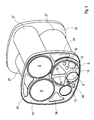
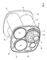
- Fig. 1 to 6 comprises an exhaust gas treatment device 1, which may preferably be used in an exhaust system of an internal combustion engine, in particular of a motor vehicle, a housing 2, which has a first end face 3, which in the Fig. 1 to 4 not shown, but only in the Fig. 5 and 6 is shown. Furthermore, the housing 2 has a second frontal bottom 4, which again only in the Fig. 5 and 6 is shown. In addition, the housing 2 has a jacket 5, which connects the two floors 3 and 4 with each other and encloses an unspecified interior of the housing 2.
- the exhaust gas treatment device 1 has a plurality of exhaust gas treatment elements 6. These are arranged to flow through in the housing 2 in parallel. For example exactly three such exhaust treatment elements 6 are shown. Likewise, it may be more or less, but at least two exhaust treatment elements 6.
- the housing 2 is equipped with an outlet port 7, which passes through the first bottom 3. Furthermore, the housing 2 contains an outlet space 8, into which at least one of the exhaust gas treatment elements 6 directly discharges on the outlet side. In the example, two of the three exhaust gas treatment elements 6 open directly into the outlet chamber 8. Furthermore, the housing 2 in the outlet chamber 8 contains a funnel body 9. This funnel body 9 communicates an exit side of one of the exhaust gas treatment elements 6 with the outlet nozzle 7 in a communicating manner.
- the funnel body 7 creates an exhaust gas-conducting connection from the outlet side of the one exhaust gas treatment element 6 to the outlet nozzle 7.
- the funnel body 9 has a funnel jacket 10, which is made permeable to exhaust gas.
- exhaust gas entering the outlet space 8 at the outlet sides of the other exhaust gas treatment elements 6 can pass from the outlet space 8 through the funnel jacket 10 to the interior of the funnel body 9 and thus to the outlet nozzle 7.
- the funnel body 9 is expediently fastened, on the one hand, to an intermediate floor 11 which delimits the outlet space 8 in relation to the first floor 3 and which is penetrated by all the exhaust-gas treatment elements 6 on the outlet side.
- the hopper body 9 is attached to the outlet port 7.
- the hopper body 9 may be integrally formed with the outlet port 7.
- the hopper body 9 may be secured to the first bottom 3 penetrated by the outlet port 7.
- the funnel jacket 10 can be designed to be permeable to exhaust gas in any desired manner. For example, this may be provided with a suitable perforation with a plurality of small openings.
- FIG. 1 shows one Embodiment in which the funnel shell 10 is equipped with a plurality of comparatively large openings 12 in order to make it permeable to exhaust gas.
- FIG. 2 shows an embodiment in which the funnel shell 10 is configured as a funnel shell segment 13, whereby a peripheral portion 14 remains free or open. In principle, arbitrary divisions are conceivable here.
- the funnel shell segment 13 may comprise half or more of the total circumference.
- FIG. 3 shows an embodiment in which the funnel shell 10 includes a plurality of cutouts 15 to make it permeable to exhaust gas.
- openings 12 may be provided.
- FIG. 4 shows again an embodiment with openings 12, wherein the in Fig. 4 shown embodiment of the in Fig. 1 shown embodiment differ by a different arrangement and by different diameters of the openings 12 from each other.
- the selection of the openings 12 or cutouts 15 or of the funnel jacket segment 13 with regard to positioning, alignment, size is expediently carried out in such a way that a desired pressure distribution is established in the outlet space 8.
- a desired pressure distribution is established in the outlet space 8.
- the housing 2 can also be equipped with an inlet pipe 16, which connects an inlet pipe 17 communicating with an inlet space 18 likewise arranged in the housing 2.
- Inlet pipe 16 and inlet port 17 are only in the Fig. 1 . 2 . 5 and 6 shown.
- the inlet space 18 is only in the Fig. 5 and 6 recognizable.
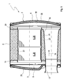
- the inlet pipe 16 has a flow-through cross-section widening in the flow direction 19 indicated by an arrow. hereby decreases in the inlet pipe 16 in the flow of pressure from so that the inlet pipe 16 shows a certain diffuser effect.
- the pressure reduction by means of the widening inlet pipe 16 promotes a homogeneous distribution of the exhaust gas to the exhaust gas treatment elements 6, which open into the inlet space 18 on the inlet side.
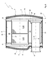
- Fig. 6 can be arranged in the housing 2, a further intermediate bottom 20 which limits the inlet space 18 relative to the second bottom 4 and which is penetrated by the exhaust gas treatment elements 6 on the inlet side.
- a pot portion 21 is formed, which is open to the inlet space 18.
- the inlet pipe 16 passes through the intermediate bottom 20 in this pot portion 21.
- the inlet pipe 16 terminates within the pot portion 21.
- a distance 22 of the inlet pipe 16 from the second bottom 4 with respect to the in Fig. 5 shown construction can be increased. Overall, this means that more volume is available in the inlet space 18, which favors the calming of the flow in the inlet space 18 and thus a uniform distribution of the exhaust gas to the various exhaust gas treatment elements 6.
- the housing 2 thus contains two intermediate floors 11 and 20. At sides facing away from one another, they delimit the outlet space 8 and the inlet space 18 on mutually facing sides the outlet space 8 associated intermediate bottom 11 communicating with the outlet 8 may be connected.
- this intermediate bottom 11 according to the Fig. 3 and 4 have a plurality of recesses 24.
- the intermediate bottom 11 may be designed perforated.
- the two end-side bottoms 3 and 4 of the housing 2 are each configured double-walled and filled with a damping material 25.
- the jacket 5 is double-walled and filled with damping material 25.
- the damping material 25 on the one hand causes a sound-damping effect, preferably in a high-frequency range. On the other hand, it also allows thermal insulation.
- the resonant space 23 can also be deliberately designed with regard to its volume so that resonance effects and / or reflection effects for sound attenuation, preferably in the low-frequency range, can be used.
- the jacket 5 is not designed double-walled.
- the resonance chamber 23 is filled with damping material 25, whereby in addition a damping in the high-frequency range can be achieved.
- the exhaust gas treatment elements 6 can according to the Fig. 5 and 6 be formed by a plurality of exhaust treatment body 26 arranged one behind the other or one after the other. It is also possible to realize the respective exhaust gas treatment elements 6 with the aid of a single continuous exhaust treatment body.
- the exhaust gas treatment elements 6 are each used in a tubular body 27, which passes through the intermediate walls 11, 20 and is suitably held on this. It can be present between the tubular body 27 and the one intermediate bottom 11, 20, a solid connection, while between the tubular body 27 and the other intermediate bottom 11, 20 may be an axially movable connection, for example in the form of a sliding seat.
- the respective exhaust gas treatment element 6 may, for example, be an oxidation catalyst, in particular an SCR catalyst. Alternatively, it is also possible to design the respective exhaust gas treatment element 6 as a particle filter. Also, combinations are possible, such as e.g. a particle filter which is catalytically actively coated or a preceding exhaust gas treatment body 26 designed as an oxidation catalyst in conjunction with a downstream exhaust gas treatment body 26 designed as a particle filter.
Landscapes
- Engineering & Computer Science (AREA)
- Chemical & Material Sciences (AREA)
- Combustion & Propulsion (AREA)
- Mechanical Engineering (AREA)
- General Engineering & Computer Science (AREA)
- Chemical Kinetics & Catalysis (AREA)
- Health & Medical Sciences (AREA)
- Toxicology (AREA)
- Exhaust Gas After Treatment (AREA)
- Exhaust Silencers (AREA)
Abstract
Description
- Die vorliegende Erfindung betrifft eine Abgasbehandlungseinrichtung für eine Abgasanlage einer Brennkraftmaschine, insbesondere eines Kraftfahrzeugs.
- Bei Abgasbehandlungseinrichtungen zur Behandlung größerer Abgasvolumenströme können mehrere Abgasbehandlungselemente parallel durchströmbar in einem Gehäuse angeordnet sein. Dabei können die Abgasbehandlungselemente in einen gemeinsamen Auslassraum einmünden. Von diesem Auslassraum führt nun ein Auslassrohr bzw. ein Auslassstutzen aus dem Gehäuse heraus. Hierbei können sich unterschiedliche Probleme ergeben. Zum einen muss das Rohr am Gehäuse relativ stabil abgestützt sein. Zum anderen sollte von den verschiedenen Abgasbehandlungselementen die Zuströmung zum Auslassrohr bzw. zum Auslassstutzen möglichst gleichförmig verteilt sein. Hier setzt die vorliegende Erfindung an.
- Die Erfindung beschäftigt sich mit dem Problem, für eine Abgasbehandlungseinrichtung der eingangs genannten Art eine verbesserte Ausführungsform anzugeben, die sich insbesondere durch eine kompakte und stabile Bauweise auszeichnet. Gleichzeitig soll eine verbesserte, insbesondere gleichmäßigere Durchströmung der Abgasbehandlungselemente realisiert werden.
- Dieses Problem wird erfindungsgemäß durch die Gegenstände der unabhängigen Ansprüche gelöst. Vorteilhafte Ausführungsformen sind Gegenstand der abhängigen Ansprüche.
- Die Erfindung beruht auf dem allgemeinen Gedanken, einen im Auslassraum mündenden Auslassstutzen mit einem Trichterkörper auszustatten, der im Auslassraum angeordnet ist und der eine Austrittsseite eines der Abgasbehandlungselemente mit dem Auslassstutzen kommunizierend verbindet. Ferner ist der Trichterkörper mit einem für Abgas durchlässigen Trichtermantel ausgestattet. Durch den abgasdurchlässigen Trichtermantel gelangt auch das aus dem wenigstens einen weiteren Abgasbehandlungselement austretende Abgas in den Trichter und somit zum Auslassstutzen. Durch den Trichterkörper kann zum einen eine intensive Abstützung des Auslassstutzens und somit eine vorteilhafte Aussteifung des Gehäuses realisiert werden. Zum anderen kann durch eine gezielte Gestaltung der Durchströmbarkeit des Trichtermantels die Druckverteilung im Auslassraum dahingehend beeinflusst werden, dass sich insgesamt ein reduzierter Durchströmungswiderstand für die Abgasbehandlungseinrichtung einstellt.
- Entsprechend einer vorteilhaften Ausführungsform kann der Trichterkörper einerseits an einem den Auslassraum begrenzenden, von den Abgasbehandlungselementen austrittsseitig durchsetzten Zwischenboden befestigt sein und andererseits am Auslassstutzen und/oder an dem vom Auslassstutzen durchsetzten Boden befestigt sein. Hierdurch schafft der Trichterkörper eine intensive Abstützung des Auslasstrichters am Zwischenboden, was die Festigkeit des Gehäuses im Bereich des Auslassstutzens signifikant erhöht.
- Bei einer anderen vorteilhaften Ausführungsform kann der Trichtermantel dadurch für Abgas durchlässig ausgestaltet sein, dass er eine Perforation aufweist und/oder dass er Ausschnitte und/oder Öffnungen aufweist und/oder dass er als Trichtermantelsegment ausgestaltet ist. Die vorgeschlagenen Maßnahmen zur Realisierung der Durchlässigkeit des Trichtermantels für Abgas eignen sich in besonderer Weise zur gezielten Strömungslenkung im Auslassraum, wodurch eine gezielte Druckverteilung im Auslassraum und somit insbesondere an den Austrittsseiten der einzelnen Abgasbehandlungselemente realisierbar ist. Ziel der Auslegung kann es insbesondere sein, an allen Abgasbehandlungselementen etwa den gleichen Durchströmungswiderstand zu erzeugen, um dadurch Abgas möglichst gleichmäßig auf die mehreren Abgasbehandlungselemente zu verteilen. Hierdurch können die durch die mehreren Abgasbehandlungselemente insgesamt zur Verfügung gestellten Oberflächen gleichmäßiger und somit besser ausgenutzt werden. Dies führt insgesamt zu einer erhöhten Effektivität der Abgasbehandlungseinrichtung, wobei gleichzeitig der Durchströmungswiderstand der Abgasbehandlungseinrichtung sinkt.
- Eine alternative Ausgestaltung der Erfindung beruht auf dem allgemeinen Gedanken, ein zu einem Einlassraum führendes Einlassrohr mit einem sich in Strömungsrichtung aufweitenden durchströmbaren Querschnitt auszustatten. Diese Maßnahme erzeugt eine gewisse Diffusorwirkung, was eine gleichmäßige Druckverteilung im Einlassraum unterstützt. Hierdurch kann die Durchströmung der Abgasbehandlungselemente homogenisiert werden, was eine Absenkung des Durchströmungswiderstands der Abgasbehandlungseinrichtung bewirkt.
- Weitere wichtige Merkmale und Vorteile der Erfindung ergeben sich aus den Unteransprüchen, aus den Zeichnungen und aus der zugehörigen Figurenbeschreibung anhand der Zeichnungen.
- Es versteht sich, dass die vorstehend genannten und die nachstehend noch zu erläuternden Merkmale nicht nur in der jeweils angegebenen Kombination, sondern auch in anderen Kombinationen oder in Alleinstellung verwendbar sind, ohne den Rahmen der vorliegenden Erfindung zu verlassen.
- Bevorzugte Ausführungsbeispiele der Erfindung sind in den Zeichnungen dargestellt und werden in der nachfolgenden Beschreibung näher erläutert, wobei sich gleiche Bezugszeichen auf gleiche oder ähnliche oder funktional gleiche Bauteile beziehen.
- Es zeigen, jeweils schematisch,
- Fig. 1 und 2
- perspektivische Ansichten einer Abgasbehandlungseinrichtung bei weggelassenem Gehäuseboden, bei verschiedenen Ausführungsformen,
- Fig. 3 und 4
- perspektivische Ansichten wie in den
Fig. 1 und2 , jedoch bei weggelassenem Gehäusemantel, bei weiteren Ausführungsformen, - Fig. 5 und 6
- Längsschnitte der Abgasbehandlungseinrichtung im Bereich eines Einlassrohrs, bei verschiedenen Ausführungsformen.
- Entsprechend den
Fig. 1 bis 6 umfasst eine Abgasbehandlungseinrichtung 1, die bevorzugt bei einer Abgasanlage einer Brennkraftmaschine, insbesondere eines Kraftfahrzeugs, zur Anwendung kommen kann, ein Gehäuse 2, das einen ersten stirnseitigen Boden 3 aufweist, der in denFig. 1 bis 4 nicht dargestellt ist, sondern nur in denFig. 5 und6 dargestellt ist. Ferner weist das Gehäuse 2 einen zweiten stirnseitigen Boden 4 auf, der wieder nur in denFig. 5 und6 dargestellt ist. Außerdem weist das Gehäuse 2 einen Mantel 5 auf, der die beiden Böden 3 und 4 miteinander verbindet und der einen nicht näher bezeichneten Innenraum des Gehäuses 2 umschließt. - Die Abgasbehandlungseinrichtung 1 weist mehrere Abgasbehandlungselemente 6 auf. Diese sind im Gehäuse 2 parallel durchströmbar angeordnet. Im Beispiel sind genau drei derartige Abgasbehandlungselemente 6 dargestellt. Ebenso können es mehr oder auch weniger, jedoch mindestens zwei Abgasbehandlungselemente 6 sein. Das Gehäuse 2 ist mit einem Auslassstutzen 7 ausgestattet, der den ersten Boden 3 durchsetzt. Ferner enthält das Gehäuse 2 einen Auslassraum 8, in den zumindest eines der Abgasbehandlungselemente 6 austrittsseitig direkt einmündet. Im Beispiel münden zwei der drei Abgasbehandlungselemente 6 unmittelbar in den Auslassraum 8 ein. Ferner enthält das Gehäuse 2 im Auslassraum 8 einen Trichterkörper 9. Dieser Trichterkörper 9 verbindet eine Austrittsseite eines der Abgasbehandlungselemente 6 mit dem Auslassstutzen 7 kommunizierend. Das heißt, der Trichterkörper 7 schafft eine abgasführende Verbindung von der Austrittsseite des einen Abgasbehandlungselements 6 zum Auslassstutzen 7. Der Trichterkörper 9 weist einen Trichtermantel 10 auf, der für Abgas durchlässig ausgestaltet ist. Somit kann Abgas, das an den Austrittsseiten der anderen Abgasbehandlungselemente 6 in den Auslassraum 8 eintritt vom Auslassraum 8 durch den Trichtermantel 10 das Innere des Trichterkörpers 9 und somit zum Auslassstutzen 7 gelangen.
- Zweckmäßig ist der Trichterkörper 9 einerseits an einem Zwischenboden 11 befestigt, der den Auslassraum 8 gegenüber dem ersten Boden 3 begrenzt und der von allen Abgasbehandlungselementen 6 austrittsseitig durchsetzt ist. Andererseits ist der Trichterkörper 9 am Auslassstutzen 7 befestigt. Insbesondere kann der Trichterkörper 9 integral mit dem Auslassstutzen 7 ausgeformt sein. Zusätzlich oder alternativ kann der Trichterkörper 9 an dem vom Auslassstutzen 7 durchsetzten ersten Boden 3 befestigt sein.
- Grundsätzlich kann der Trichtermantel 10 auf beliebige Weise abgasdurchlässig ausgestaltet sein. Beispielsweise kann hierzu eine geeignete Perforation mit einer Vielzahl kleiner Öffnungen vorgesehen sein.
Figur 1 zeigt eine Ausführungsform, bei welcher der Trichtermantel 10 mit mehreren, vergleichsweise großen Öffnungen 12 ausgestattet ist, um ihn abgasdurchlässig auszugestalten.Figur 2 zeigt eine Ausführungsform, bei welcher der Trichtermantel 10 als Trichtermantelsegment 13 ausgestaltet ist, wodurch ein Umfangsabschnitt 14 frei oder offen bleibt. Denkbar sind hier grundsätzlich beliebige Teilungen. Beispielsweise kann das Trichtermantelsegment 13 die Hälfte oder mehr des Gesamtumfangs umfassen.Figur 3 zeigt eine Ausführungsform, bei welcher der Trichtermantel 10 mehrere Ausschnitte 15 enthält, um ihn für Abgas durchlässig zu machen. Optional können außerdem auch Öffnungen 12 vorgesehen sein.Figur 4 zeigt wieder eine Ausführungsform mit Öffnungen 12, wobei sich die inFig. 4 gezeigte Ausführungsform von der inFig. 1 gezeigten Ausführungsform durch eine unterschiedliche Anordnung sowie durch unterschiedliche Durchmesser der Öffnungen 12 voneinander unterscheiden. - Die Auswahl der Öffnungen 12 bzw. Ausschnitte 15 bzw. des Trichtermantelsegments 13 hinsichtlich Positionierung, Ausrichtung, Größe erfolgt zweckmäßig derart, dass sich im Auslassraum 8 eine gewünschte Druckverteilung einstellt. Hierdurch kann das Abströmverhalten und somit das Durchströmungsverhalten der einzelnen Abgasbehandlungselemente 6 beeinflusst werden.
- Das Gehäuse 2 kann außerdem mit einem Einlassrohr 16 ausgestattet sein, das einen Einlassstutzen 17 mit einem ebenfalls im Gehäuse 2 angeordneten Einlassraum 18 kommunizierend verbindet. Einlassrohr 16 und Einlassstutzen 17 sind nur in den
Fig. 1 ,2 ,5 und6 dargestellt. Der Einlassraum 18 ist nur in denFig. 5 und6 erkennbar. Bei der inFig. 5 gezeigten Ausführungsform besitzt das Einlassrohr 16 einen sich in der durch einen Pfeil angedeuteten Strömungsrichtung 19 aufweitenden durchströmbaren Querschnitt auf. Hierdurch nimmt im Einlassrohr 16 bei der Durchströmung der Druck ab, so dass das Einlassrohr 16 eine gewisse Diffusorwirkung zeigt. Die Druckabsenkung mit Hilfe des sich aufweitenden Einlassrohrs 16 begünstigt eine homogene Verteilung des Abgases auf die Abgasbehandlungselemente 6, die in den Einlassraum 18 eintrittsseitig einmünden. - Ebenso ist jedoch eine Ausführungsform wie in
Fig. 6 möglich, bei welcher das Einlassrohr 16 einen in der Strömungsrichtung 19 konstanten durchströmbaren Querschnitt besitzt. - Gemäß
Fig. 6 kann im Gehäuse 2 ein weiterer Zwischenboden 20 angeordnet sein, der den Einlassraum 18 gegenüber dem zweiten Boden 4 begrenzt und der von den Abgasbehandlungselementen 6 eintrittsseitig durchsetzt ist. An diesem Zwischenboden 20 ist ein Topfabschnitt 21 ausgeformt, der zum Einlassraum 18 hin offen ist. Das Einlassrohr 16 durchsetzt den Zwischenboden 20 in diesen Topfabschnitt 21. Dabei endet das Einlassrohr 16 innerhalb des Topfabschnitts 21. Durch diese Bauweise kann ein Abstand 22 des Einlassrohrs 16 vom zweiten Boden 4 gegenüber der inFig. 5 gezeigten Bauweise vergrößert werden. Insgesamt steht dadurch im Einlassraum 18 mehr Volumen zur Verfügung, was die Beruhigung der Strömung im Einlassraum 18 und somit eine gleichmäßige Verteilung des Abgases auf die verschiedenen Abgasbehandlungselemente 6 begünstigt. - Bei den hier gezeigten Beispielen enthält das Gehäuse 2 somit zwei Zwischenböden 11 und 20. An voneinander abgewandten Seiten begrenzen sie zum einen den Auslassraum 8 und zum anderen den Einlassraum 18. An einander zugewandten Seiten begrenzen sie einen Resonanzraum 23. Besagter Resonanzraum 23 kann durch den dem Auslassraum 8 zugeordneten Zwischenboden 11 mit dem Auslassraum 8 kommunizierend verbunden sein.
- Hierzu kann dieser Zwischenboden 11 gemäß den
Fig. 3 und4 mehrere Aussparungen 24 aufweisen. Ebenso kann der Zwischenboden 11 perforiert ausgestaltet sein. - In den Beispielen der
Fig. 5 und6 sind die beiden stirnseitigen Böden 3 und 4 des Gehäuses 2 jeweils doppelwandig ausgestaltet und mit einem Dämpfungsmaterial 25 befüllt. Im Beispiel derFig. 6 ist außerdem der Mantel 5 doppelwandig ausgestaltet und mit Dämpfungsmaterial 25 befüllt. Das Dämpfungsmaterial 25 bewirkt zum einen eine schalldämpfende Wirkung, vorzugsweise in einem hochfrequenten Bereich. Zum anderen ermöglicht es auch eine thermische Isolation. Auch der Resonanzraum 23 kann hinsichtlich seines Volumens gezielt so ausgelegt werden, dass Resonanzeffekte und/oder Reflektionseffekte zur Schalldämpfung, bevorzugt im tieffrequenten Bereich nutzbar sind. Bei der inFig. 5 gezeigten Ausführungsform ist der Mantel 5 nicht doppelwandig ausgestaltet. Dafür ist bei dieser Ausführungsform der Resonanzraum 23 mit Dämpfungsmaterial 25 befüllt, wodurch zusätzlich eine Bedämpfung im hochfrequenten Bereich erzielbar ist. - Die Abgasbehandlungselemente 6 können gemäß den
Fig. 5 und6 durch mehrere, hintereinander angeordnete bzw. nacheinander durchströmbare Abgasbehandlungskörper 26 gebildet sein. Ebenso ist es möglich, die jeweiligen Abgasbehandlungselemente 6 mit Hilfe eines einzigen durchgehenden Abgasbehandlungskörpers zu realisieren. Die Abgasbehandlungselemente 6 sind jeweils in einem Rohrkörper 27 eingesetzt, der die Zwischenwände 11, 20 durchsetzt und zweckmäßig an diesen gehalten ist. Dabei kann zwischen dem Rohrkörper 27 und dem einen Zwischenboden 11, 20 eine feste Verbindung vorliegen, während zwischen dem Rohrkörper 27 und dem anderen Zwischenboden 11, 20 eine axial bewegliche Verbindung vorliegen kann, zum Beispiel in Form eines Schiebesitzes. - Das jeweilige Abgasbehandlungselement 6 kann bspw. ein Oxidationskatalysator sein, und zwar insbesondere ein SCR-Katalysator. Alternativ ist es ebenso möglich, das jeweilige Abgasbehandlungselement 6 als Partikelfilter auszugestalten. Auch sind Kombinationen möglich, wie z.B. ein als katalytisch aktiv beschichtetes Partikelfilter oder ein als Oxidationskatalysator ausgestalteter vorausgehender Abgasbehandlungskörper 26 in Verbindung mit einem als Partikelfilter ausgestalteten nachfolgenden Abgasbehandlungskörper 26.
Claims (10)
- Abgasbehandlungseinrichtung für eine Abgasanlage einer Brennkraftmaschine, insbesondere eines Kraftfahrzeugs, mit einem Gehäuse (2),
gekennzeichnet durch- mehrere, im Gehäuse (2) angeordnete, parallel durchströmbare Abgasbehandlungselemente (6),- einen Auslassstutzen (7), der einen Boden (3) des Gehäuses (2) durchsetzt,- einen im Gehäuse (2) angeordneten Auslassraum (8), in den zumindest eines der Abgasbehandlungselemente (6) austrittsseitig einmündet,- einen im Auslassraum (8) angeordneten Trichterkörper (9), der eine Austrittsseite eines der Abgasbehandlungselemente (6) mit dem Auslassstutzen (7) kommunizierend verbindet und dessen Trichtermantel (10) für Abgas durchlässig ausgestaltet ist. - Abgasbehandlungseinrichtung nach Anspruch 1,
dadurch gekennzeichnet,
dass der Trichterkörper (9) einerseits an einem den Auslassraum (8) begrenzenden, von den Abgasbehandlungselementen (6) austrittsseitig durchsetzten Zwischenboden (11) befestigt ist und andererseits am Auslassstutzen (7) und/oder an dem vom Auslassstutzen (7) durchsetzten Boden (3) befestigt ist. - Abgasbehandlungseinrichtung nach Anspruch 1 oder 2,
dadurch gekennzeichnet,
dass der Trichtermantel (10) dadurch für Abgas durchlässig ist, dass er eine Perforation und/oder Ausschnitte (15) und/oder Öffnungen (12) aufweist und/oder dass er als Trichtermantelsegment (13) ausgestaltet ist. - Abgasbehandlungseinrichtung nach dem Oberbegriff des Anspruchs 1, insbesondere nach einem der vorhergenden Ansprüche,
dadurch gekennzeichnet,
dass ein Einlassrohr (16) vorgesehen ist, das einen Einlassstutzen (17) mit einem im Gehäuse (2) angeordneten Einlassraum (18) kommunizierend verbindet und das einen sich in Strömungsrichtung (19) aufweitenden durchströmbaren Querschnitt aufweist. - Abgasbehandlungseinrichtung nach einem der Ansprüche 1 bis 4,
dadurch gekennzeichnet,
dass ein Einlassrohr (16) vorgesehen ist, das einen Einlassstutzen (17) mit einem im Gehäuse (2) angeordneten Einlassraum (18) kommunizierend verbindet, und das einen den Einlassraum (18) begrenzenden Zwischenboden (20) durchsetzt, wobei am Zwischenboden (20) ein zum Einlassraum (18) offener Topfabschnitt (21) ausgeformt ist, in dem das Einlassrohr (16) den Zwischenboden (20) durchsetzt. - Abgasbehandlungseinrichtung nach einem der Ansprüche 1 bis 5,
dadurch gekennzeichnet,
dass im Gehäuse (2) zwei Zwischenböden (11, 20) angeordnet sind, die von den Abgasbehandlungselementen (6) durchsetzt sind und die einen Resonanzraum (23) begrenzen. - Abgasbehandlungseinrichtung nach Anspruch 6,
dadurch gekennzeichnet,
dass der Resonanzraum (23) durch einen der Zwischenböden (11) mit dem Auslassraum (8) kommuniziert. - Abgasbehandlungseinrichtung nach einem der Ansprüche 1 bis 7,
dadurch gekennzeichnet,- dass stirnseitige Böden (3, 4) des Gehäuses (2) doppelwandig ausgestaltet und mit Dämpfungsmaterial (25) befüllt sind, und/oder- dass ein Mantel (5) des Gehäuses (2) doppelwandig ausgestaltet und mit Dämpfungsmaterial (25) befüllt ist. - Abgasbehandlungseinrichtung nach einem der Ansprüche 1 bis 8,
dadurch gekennzeichnet,
dass das jeweilige Abgasbehandlungselement (6) einen einzigen Abgasbehandlungskörper oder mehrere hintereinander angeordnete Abgasbehandlungskörper (26) besitzt. - Abgasbehandlungseinrichtung nach einem der Ansprüche 1 bis 9,
dadurch gekennzeichnet,
dass das jeweilige Abgasbehandlungselement (6) als Oxidationskatalysator, insbesondere SCR-Katalysator, oder als Partikelfilter ausgestaltet ist.
Applications Claiming Priority (1)
| Application Number | Priority Date | Filing Date | Title |
|---|---|---|---|
| DE102008022081A DE102008022081A1 (de) | 2008-05-05 | 2008-05-05 | Abgasbehandlungseinrichtung |
Publications (2)
| Publication Number | Publication Date |
|---|---|
| EP2116699A1 true EP2116699A1 (de) | 2009-11-11 |
| EP2116699B1 EP2116699B1 (de) | 2016-08-10 |
Family
ID=40812223
Family Applications (1)
| Application Number | Title | Priority Date | Filing Date |
|---|---|---|---|
| EP09155941.9A Active EP2116699B1 (de) | 2008-05-05 | 2009-03-24 | Abgasbehandlungseinrichtung |
Country Status (3)
| Country | Link |
|---|---|
| US (1) | US8336301B2 (de) |
| EP (1) | EP2116699B1 (de) |
| DE (1) | DE102008022081A1 (de) |
Families Citing this family (26)
| Publication number | Priority date | Publication date | Assignee | Title |
|---|---|---|---|---|
| DE102010008999A1 (de) * | 2010-02-24 | 2011-08-25 | J. Eberspächer GmbH & Co. KG, 73730 | Abgasbehandlungseinrichtung |
| DE102010015271A1 (de) | 2010-04-15 | 2011-10-20 | J. Eberspächer GmbH & Co. KG | Abgasbehandlungseinrichtung |
| DE102010034743A1 (de) | 2010-08-19 | 2012-02-23 | J. Eberspächer GmbH & Co. KG | Abgasreinigungsvorrichtung, Abgasanlage, Ausbauverfahren |
| KR101425872B1 (ko) * | 2011-01-11 | 2014-08-05 | 대동공업주식회사 | 디젤엔진 배기가스 후처리 장치 |
| US8609030B2 (en) * | 2011-03-04 | 2013-12-17 | Tenneco Automotive Operating Company Inc. | Exhaust aftertreatment device with integrated shell and baffle |
| US8776509B2 (en) | 2011-03-09 | 2014-07-15 | Tenneco Automotive Operating Company Inc. | Tri-flow exhaust treatment device with reductant mixing tube |
| US20120285902A1 (en) * | 2011-05-10 | 2012-11-15 | Cummins Filtration Ip Inc. | Filter with Shaped Flow Path Combinations |
| US9086007B2 (en) * | 2012-12-21 | 2015-07-21 | Caterpillar Inc. | System and method for accommodating aftertreatment bricks |
| JP6055305B2 (ja) * | 2012-12-26 | 2016-12-27 | ヤンマー株式会社 | 排気ガス浄化装置 |
| JP6084487B2 (ja) * | 2013-03-11 | 2017-02-22 | 本田技研工業株式会社 | 触媒コンバータ付きマフラ |
| US9869230B2 (en) * | 2013-04-30 | 2018-01-16 | Faurecia Emissions Control Technologies, Usa, Llc | Cast mounted sub-structure for end module |
| US11136910B2 (en) | 2017-06-06 | 2021-10-05 | Cummins Emission Solutions Inc. | Systems and methods for mixing exhaust gases and reductant in an aftertreatment system |
| WO2019055922A1 (en) | 2017-09-15 | 2019-03-21 | Eberspaecher North America, Inc. | EXHAUST GAS POST-TREATMENT APPARATUS |
| US12503969B2 (en) | 2019-12-03 | 2025-12-23 | Cummins Emission Solutions Inc. | Reductant delivery system for exhaust gas aftertreatment system |
| CN120132644A (zh) | 2020-02-27 | 2025-06-13 | 康明斯排放处理公司 | 用于后处理系统中的混合器 |
| GB2631666A (en) * | 2020-10-22 | 2025-01-08 | Cummins Emission Solutions Inc | Exhaust gas aftertreatment system |
| GB2618011B (en) | 2021-02-02 | 2025-02-26 | Cummins Emission Solutions Inc | Exhaust gas aftertreatment systems |
| US12359600B2 (en) | 2021-02-19 | 2025-07-15 | Purem Novi, Inc. | Exhaust aftertreatment apparatus |
| US11808187B2 (en) * | 2021-03-01 | 2023-11-07 | Caterpillar Inc. | Noise attenuation components |
| US12123337B2 (en) | 2021-03-18 | 2024-10-22 | Cummins Emission Solutions Inc. | Aftertreatment systems |
| CN117396668A (zh) | 2021-07-27 | 2024-01-12 | 康明斯排放处理公司 | 废气后处理系统 |
| CN119643152A (zh) | 2021-08-23 | 2025-03-18 | 康明斯排放处理公司 | 用于后处理系统的出口取样系统 |
| EP4396450A1 (de) | 2021-08-31 | 2024-07-10 | Purem Novi, Inc. | Abgasnachbehandlungsvorrichtung |
| USD1042545S1 (en) | 2022-04-21 | 2024-09-17 | Cummins Emission Solutions Inc. | Aftertreatment system |
| USD1042544S1 (en) | 2022-04-21 | 2024-09-17 | Cummins Emission Solutions Inc. | Aftertreatment system |
| WO2024112898A1 (en) | 2022-11-22 | 2024-05-30 | Purem Novi, Inc. | Thermal enhancer for exhaust aftertreatment apparatus |
Citations (5)
| Publication number | Priority date | Publication date | Assignee | Title |
|---|---|---|---|---|
| US4730454A (en) * | 1985-10-26 | 1988-03-15 | FEV Forschungsgesellschaft fur Energie-Technik und Verbrennungsmotoren mbH | Process and system for the oxidation of engine emission particulates deposited in a particulate filter trap |
| US5212948A (en) * | 1990-09-27 | 1993-05-25 | Donaldson Company, Inc. | Trap apparatus with bypass |
| US5396764A (en) * | 1994-02-14 | 1995-03-14 | Ford Motor Company | Spark ignition engine exhaust system |
| EP0953741A1 (de) * | 1998-04-29 | 1999-11-03 | Automobiles Peugeot | Katalysator und Schallbehandlungsgerät einer Auspuffleitung mit Doppelströmung |
| US20040202591A1 (en) * | 2003-04-11 | 2004-10-14 | Eberhard Jacob | Combination exhaust gas post treatment/muffler device in the exhaust gas section of an internal combustion engine |
Family Cites Families (16)
| Publication number | Priority date | Publication date | Assignee | Title |
|---|---|---|---|---|
| US3989471A (en) * | 1975-04-14 | 1976-11-02 | Tenneco Inc. | Radial flow catalytic converter having thermal expansion compensating means |
| US4108276A (en) * | 1976-09-20 | 1978-08-22 | Nelson Industries, Inc. | Vent silencer |
| US4601168A (en) * | 1984-12-12 | 1986-07-22 | Harris Harold L | Noise and emission control apparatus |
| US5009065A (en) * | 1988-08-15 | 1991-04-23 | Arvin Industries, Inc. | Tuned exhaust processor assembly |
| EP0393257A1 (de) * | 1989-04-17 | 1990-10-24 | Emitec Gesellschaft für Emissionstechnologie mbH | Dieselrussfilter mit zusätzlicher Einrichtung zur Reduktion von Stickoxyden und/oder Oxydation von Kohlenmonoxyd |
| US5016438A (en) * | 1989-09-25 | 1991-05-21 | Harris International Sales Corporation | Emission control apparatus |
| US5198625A (en) * | 1991-03-25 | 1993-03-30 | Alexander Borla | Exhaust muffler for internal combustion engines |
| US5426269A (en) * | 1992-06-02 | 1995-06-20 | Donaldson Company, Inc. | Muffler with catalytic converter arrangement; and method |
| US6935461B2 (en) * | 1998-08-18 | 2005-08-30 | Gregory M. Marocco | Exhaust sound and emission control systems |
| JP4505114B2 (ja) * | 2000-08-23 | 2010-07-21 | 東京濾器株式会社 | 触媒マフラ |
| DE10042542A1 (de) * | 2000-08-30 | 2002-03-14 | Eberspaecher J Gmbh & Co | Abgasreinigungssystem für Kraftfahrzeuge, insbesondere Diesel-Nutzfahrzeuge |
| US7384609B2 (en) * | 2003-01-29 | 2008-06-10 | Brp-Rotax Gmbh & Co. Kg | Pre-converter device for cleaning exhaust gas for an internal combustion engine |
| DE10356000B4 (de) * | 2003-11-27 | 2006-01-12 | J. Eberspächer GmbH & Co. KG | Schalldämpfer mit integriertem Katalysator |
| JP2006151298A (ja) * | 2004-11-30 | 2006-06-15 | Honda Motor Co Ltd | 燃料電池自動車 |
| US7380397B2 (en) * | 2005-09-08 | 2008-06-03 | Chih-Kuang Chang | Automobile exhaust pipe assembly |
| EP1895118A1 (de) * | 2006-08-29 | 2008-03-05 | Tecumseh Products Company | Passiver Sekundärluftschalldämpfer |
-
2008
- 2008-05-05 DE DE102008022081A patent/DE102008022081A1/de not_active Withdrawn
-
2009
- 2009-03-24 EP EP09155941.9A patent/EP2116699B1/de active Active
- 2009-05-05 US US12/435,501 patent/US8336301B2/en active Active
Patent Citations (5)
| Publication number | Priority date | Publication date | Assignee | Title |
|---|---|---|---|---|
| US4730454A (en) * | 1985-10-26 | 1988-03-15 | FEV Forschungsgesellschaft fur Energie-Technik und Verbrennungsmotoren mbH | Process and system for the oxidation of engine emission particulates deposited in a particulate filter trap |
| US5212948A (en) * | 1990-09-27 | 1993-05-25 | Donaldson Company, Inc. | Trap apparatus with bypass |
| US5396764A (en) * | 1994-02-14 | 1995-03-14 | Ford Motor Company | Spark ignition engine exhaust system |
| EP0953741A1 (de) * | 1998-04-29 | 1999-11-03 | Automobiles Peugeot | Katalysator und Schallbehandlungsgerät einer Auspuffleitung mit Doppelströmung |
| US20040202591A1 (en) * | 2003-04-11 | 2004-10-14 | Eberhard Jacob | Combination exhaust gas post treatment/muffler device in the exhaust gas section of an internal combustion engine |
Also Published As
| Publication number | Publication date |
|---|---|
| US8336301B2 (en) | 2012-12-25 |
| EP2116699B1 (de) | 2016-08-10 |
| DE102008022081A1 (de) | 2009-11-12 |
| US20090272106A1 (en) | 2009-11-05 |
Similar Documents
| Publication | Publication Date | Title |
|---|---|---|
| EP2116699B1 (de) | Abgasbehandlungseinrichtung | |
| DE102005002289B4 (de) | Abgasbehandlungssystem | |
| EP2233708B2 (de) | Abgasbehandlungseinrichtung | |
| EP2233709B1 (de) | Abgasbehandlungseinrichtung | |
| DE102012218565B4 (de) | Abgasanlage mit Leitungselement | |
| DE102008031136B4 (de) | Abgasbehandlungseinrichtung | |
| DE102008046222B4 (de) | Abgasnachbehandlungseinrichtung | |
| EP3168437B1 (de) | Schalldämpfer für eine abgasanlage | |
| EP2363581B1 (de) | Abgasbehandlungseinrichtung | |
| DE102011089969B4 (de) | Abgasbehandlungsvorrichtung | |
| DE102014222698A1 (de) | Abgasnachbehandlungseinrichtung mit Injektionsabschnitt | |
| DE10316799A1 (de) | Kombinierte Abgasnachbehandlungs-/Schalldämpfungsvorrichtung im Abgasstrang einer Brennkraftmaschine | |
| DE102010008403A1 (de) | Schalldämpfer | |
| DE102014213746A1 (de) | Statischer Mischer | |
| DE102014205782A1 (de) | Abgasreinigungsvorrichtung für Brennkraftmaschinen | |
| DE10316802A1 (de) | Kombinierte Abgasnachbehandlungs-/Schalldämpfungsvorrichtung im Abgasstrang einer Brennkraftmaschine | |
| DE112009000479T5 (de) | Abgasbehandlungssystem | |
| EP3303786A1 (de) | Mischer in einem abgassystem | |
| DE112009000884B4 (de) | Schalldämpfer für die Abgasleitung von Automobilen | |
| DE102011120221A1 (de) | Mischer für eine Abgasanlage und Abgasanlage | |
| DE10300384B4 (de) | Abgasanlage | |
| DE102006038204B4 (de) | Eingangstrichter für eine Abgasbehandlungseinrichtung | |
| DE102008023553A1 (de) | Schalldämpfer für eine Abgasanlage | |
| DE29512732U1 (de) | Schalldämpfer für die Abgasanlage eines Verbrennungsmotors | |
| DE10357941B4 (de) | Schalldämpfer für eine Abgasanlage |
Legal Events
| Date | Code | Title | Description |
|---|---|---|---|
| PUAI | Public reference made under article 153(3) epc to a published international application that has entered the european phase |
Free format text: ORIGINAL CODE: 0009012 |
|
| AK | Designated contracting states |
Kind code of ref document: A1 Designated state(s): AT BE BG CH CY CZ DE DK EE ES FI FR GB GR HR HU IE IS IT LI LT LU LV MC MK MT NL NO PL PT RO SE SI SK TR |
|
| AX | Request for extension of the european patent |
Extension state: AL BA RS |
|
| 17P | Request for examination filed |
Effective date: 20100511 |
|
| AKX | Designation fees paid |
Designated state(s): AT BE BG CH CY CZ DE DK EE ES FI FR GB GR HR HU IE IS IT LI LT LU LV MC MK MT NL NO PL PT RO SE SI SK TR |
|
| 17Q | First examination report despatched |
Effective date: 20120112 |
|
| RAP1 | Party data changed (applicant data changed or rights of an application transferred) |
Owner name: EBERSPAECHER EXHAUST TECHNOLOGY GMBH & CO. KG |
|
| GRAP | Despatch of communication of intention to grant a patent |
Free format text: ORIGINAL CODE: EPIDOSNIGR1 |
|
| RIC1 | Information provided on ipc code assigned before grant |
Ipc: F01N 13/00 20100101ALI20160223BHEP Ipc: F01N 3/28 20060101ALI20160223BHEP Ipc: F01N 3/033 20060101AFI20160223BHEP |
|
| INTG | Intention to grant announced |
Effective date: 20160318 |
|
| GRAS | Grant fee paid |
Free format text: ORIGINAL CODE: EPIDOSNIGR3 |
|
| GRAA | (expected) grant |
Free format text: ORIGINAL CODE: 0009210 |
|
| AK | Designated contracting states |
Kind code of ref document: B1 Designated state(s): AT BE BG CH CY CZ DE DK EE ES FI FR GB GR HR HU IE IS IT LI LT LU LV MC MK MT NL NO PL PT RO SE SI SK TR |
|
| REG | Reference to a national code |
Ref country code: GB Ref legal event code: FG4D Free format text: NOT ENGLISH |
|
| REG | Reference to a national code |
Ref country code: CH Ref legal event code: EP Ref country code: AT Ref legal event code: REF Ref document number: 819266 Country of ref document: AT Kind code of ref document: T Effective date: 20160815 |
|
| REG | Reference to a national code |
Ref country code: IE Ref legal event code: FG4D Free format text: LANGUAGE OF EP DOCUMENT: GERMAN |
|
| REG | Reference to a national code |
Ref country code: DE Ref legal event code: R096 Ref document number: 502009012926 Country of ref document: DE |
|
| REG | Reference to a national code |
Ref country code: LT Ref legal event code: MG4D |
|
| REG | Reference to a national code |
Ref country code: NL Ref legal event code: MP Effective date: 20160810 |
|
| PG25 | Lapsed in a contracting state [announced via postgrant information from national office to epo] |
Ref country code: NL Free format text: LAPSE BECAUSE OF FAILURE TO SUBMIT A TRANSLATION OF THE DESCRIPTION OR TO PAY THE FEE WITHIN THE PRESCRIBED TIME-LIMIT Effective date: 20160810 Ref country code: IS Free format text: LAPSE BECAUSE OF FAILURE TO SUBMIT A TRANSLATION OF THE DESCRIPTION OR TO PAY THE FEE WITHIN THE PRESCRIBED TIME-LIMIT Effective date: 20161210 Ref country code: LT Free format text: LAPSE BECAUSE OF FAILURE TO SUBMIT A TRANSLATION OF THE DESCRIPTION OR TO PAY THE FEE WITHIN THE PRESCRIBED TIME-LIMIT Effective date: 20160810 Ref country code: HR Free format text: LAPSE BECAUSE OF FAILURE TO SUBMIT A TRANSLATION OF THE DESCRIPTION OR TO PAY THE FEE WITHIN THE PRESCRIBED TIME-LIMIT Effective date: 20160810 Ref country code: FI Free format text: LAPSE BECAUSE OF FAILURE TO SUBMIT A TRANSLATION OF THE DESCRIPTION OR TO PAY THE FEE WITHIN THE PRESCRIBED TIME-LIMIT Effective date: 20160810 Ref country code: NO Free format text: LAPSE BECAUSE OF FAILURE TO SUBMIT A TRANSLATION OF THE DESCRIPTION OR TO PAY THE FEE WITHIN THE PRESCRIBED TIME-LIMIT Effective date: 20161110 |
|
| PG25 | Lapsed in a contracting state [announced via postgrant information from national office to epo] |
Ref country code: GR Free format text: LAPSE BECAUSE OF FAILURE TO SUBMIT A TRANSLATION OF THE DESCRIPTION OR TO PAY THE FEE WITHIN THE PRESCRIBED TIME-LIMIT Effective date: 20161111 Ref country code: ES Free format text: LAPSE BECAUSE OF FAILURE TO SUBMIT A TRANSLATION OF THE DESCRIPTION OR TO PAY THE FEE WITHIN THE PRESCRIBED TIME-LIMIT Effective date: 20160810 Ref country code: LV Free format text: LAPSE BECAUSE OF FAILURE TO SUBMIT A TRANSLATION OF THE DESCRIPTION OR TO PAY THE FEE WITHIN THE PRESCRIBED TIME-LIMIT Effective date: 20160810 Ref country code: SE Free format text: LAPSE BECAUSE OF FAILURE TO SUBMIT A TRANSLATION OF THE DESCRIPTION OR TO PAY THE FEE WITHIN THE PRESCRIBED TIME-LIMIT Effective date: 20160810 Ref country code: PL Free format text: LAPSE BECAUSE OF FAILURE TO SUBMIT A TRANSLATION OF THE DESCRIPTION OR TO PAY THE FEE WITHIN THE PRESCRIBED TIME-LIMIT Effective date: 20160810 Ref country code: PT Free format text: LAPSE BECAUSE OF FAILURE TO SUBMIT A TRANSLATION OF THE DESCRIPTION OR TO PAY THE FEE WITHIN THE PRESCRIBED TIME-LIMIT Effective date: 20161212 |
|
| REG | Reference to a national code |
Ref country code: FR Ref legal event code: PLFP Year of fee payment: 9 |
|
| PG25 | Lapsed in a contracting state [announced via postgrant information from national office to epo] |
Ref country code: EE Free format text: LAPSE BECAUSE OF FAILURE TO SUBMIT A TRANSLATION OF THE DESCRIPTION OR TO PAY THE FEE WITHIN THE PRESCRIBED TIME-LIMIT Effective date: 20160810 Ref country code: RO Free format text: LAPSE BECAUSE OF FAILURE TO SUBMIT A TRANSLATION OF THE DESCRIPTION OR TO PAY THE FEE WITHIN THE PRESCRIBED TIME-LIMIT Effective date: 20160810 |
|
| REG | Reference to a national code |
Ref country code: DE Ref legal event code: R097 Ref document number: 502009012926 Country of ref document: DE |
|
| PG25 | Lapsed in a contracting state [announced via postgrant information from national office to epo] |
Ref country code: CZ Free format text: LAPSE BECAUSE OF FAILURE TO SUBMIT A TRANSLATION OF THE DESCRIPTION OR TO PAY THE FEE WITHIN THE PRESCRIBED TIME-LIMIT Effective date: 20160810 Ref country code: BG Free format text: LAPSE BECAUSE OF FAILURE TO SUBMIT A TRANSLATION OF THE DESCRIPTION OR TO PAY THE FEE WITHIN THE PRESCRIBED TIME-LIMIT Effective date: 20161110 Ref country code: SK Free format text: LAPSE BECAUSE OF FAILURE TO SUBMIT A TRANSLATION OF THE DESCRIPTION OR TO PAY THE FEE WITHIN THE PRESCRIBED TIME-LIMIT Effective date: 20160810 Ref country code: DK Free format text: LAPSE BECAUSE OF FAILURE TO SUBMIT A TRANSLATION OF THE DESCRIPTION OR TO PAY THE FEE WITHIN THE PRESCRIBED TIME-LIMIT Effective date: 20160810 |
|
| PLBE | No opposition filed within time limit |
Free format text: ORIGINAL CODE: 0009261 |
|
| STAA | Information on the status of an ep patent application or granted ep patent |
Free format text: STATUS: NO OPPOSITION FILED WITHIN TIME LIMIT |
|
| 26N | No opposition filed |
Effective date: 20170511 |
|
| PG25 | Lapsed in a contracting state [announced via postgrant information from national office to epo] |
Ref country code: SI Free format text: LAPSE BECAUSE OF FAILURE TO SUBMIT A TRANSLATION OF THE DESCRIPTION OR TO PAY THE FEE WITHIN THE PRESCRIBED TIME-LIMIT Effective date: 20160810 |
|
| REG | Reference to a national code |
Ref country code: CH Ref legal event code: PL |
|
| PG25 | Lapsed in a contracting state [announced via postgrant information from national office to epo] |
Ref country code: MC Free format text: LAPSE BECAUSE OF FAILURE TO SUBMIT A TRANSLATION OF THE DESCRIPTION OR TO PAY THE FEE WITHIN THE PRESCRIBED TIME-LIMIT Effective date: 20160810 |
|
| REG | Reference to a national code |
Ref country code: IE Ref legal event code: MM4A |
|
| PG25 | Lapsed in a contracting state [announced via postgrant information from national office to epo] |
Ref country code: LU Free format text: LAPSE BECAUSE OF NON-PAYMENT OF DUE FEES Effective date: 20170324 |
|
| PG25 | Lapsed in a contracting state [announced via postgrant information from national office to epo] |
Ref country code: IE Free format text: LAPSE BECAUSE OF NON-PAYMENT OF DUE FEES Effective date: 20170324 Ref country code: CH Free format text: LAPSE BECAUSE OF NON-PAYMENT OF DUE FEES Effective date: 20170331 Ref country code: LI Free format text: LAPSE BECAUSE OF NON-PAYMENT OF DUE FEES Effective date: 20170331 |
|
| REG | Reference to a national code |
Ref country code: BE Ref legal event code: MM Effective date: 20170331 |
|
| REG | Reference to a national code |
Ref country code: FR Ref legal event code: PLFP Year of fee payment: 10 |
|
| REG | Reference to a national code |
Ref country code: AT Ref legal event code: MM01 Ref document number: 819266 Country of ref document: AT Kind code of ref document: T Effective date: 20170324 |
|
| PG25 | Lapsed in a contracting state [announced via postgrant information from national office to epo] |
Ref country code: BE Free format text: LAPSE BECAUSE OF NON-PAYMENT OF DUE FEES Effective date: 20170331 |
|
| PGFP | Annual fee paid to national office [announced via postgrant information from national office to epo] |
Ref country code: IT Payment date: 20180322 Year of fee payment: 10 |
|
| PG25 | Lapsed in a contracting state [announced via postgrant information from national office to epo] |
Ref country code: AT Free format text: LAPSE BECAUSE OF NON-PAYMENT OF DUE FEES Effective date: 20170324 |
|
| PG25 | Lapsed in a contracting state [announced via postgrant information from national office to epo] |
Ref country code: MT Free format text: LAPSE BECAUSE OF FAILURE TO SUBMIT A TRANSLATION OF THE DESCRIPTION OR TO PAY THE FEE WITHIN THE PRESCRIBED TIME-LIMIT Effective date: 20160810 |
|
| PG25 | Lapsed in a contracting state [announced via postgrant information from national office to epo] |
Ref country code: HU Free format text: LAPSE BECAUSE OF FAILURE TO SUBMIT A TRANSLATION OF THE DESCRIPTION OR TO PAY THE FEE WITHIN THE PRESCRIBED TIME-LIMIT; INVALID AB INITIO Effective date: 20090324 |
|
| PG25 | Lapsed in a contracting state [announced via postgrant information from national office to epo] |
Ref country code: CY Free format text: LAPSE BECAUSE OF NON-PAYMENT OF DUE FEES Effective date: 20160810 |
|
| PG25 | Lapsed in a contracting state [announced via postgrant information from national office to epo] |
Ref country code: MK Free format text: LAPSE BECAUSE OF FAILURE TO SUBMIT A TRANSLATION OF THE DESCRIPTION OR TO PAY THE FEE WITHIN THE PRESCRIBED TIME-LIMIT Effective date: 20160810 |
|
| PG25 | Lapsed in a contracting state [announced via postgrant information from national office to epo] |
Ref country code: IT Free format text: LAPSE BECAUSE OF NON-PAYMENT OF DUE FEES Effective date: 20190324 |
|
| PG25 | Lapsed in a contracting state [announced via postgrant information from national office to epo] |
Ref country code: TR Free format text: LAPSE BECAUSE OF FAILURE TO SUBMIT A TRANSLATION OF THE DESCRIPTION OR TO PAY THE FEE WITHIN THE PRESCRIBED TIME-LIMIT Effective date: 20160810 |
|
| REG | Reference to a national code |
Ref country code: DE Ref legal event code: R081 Ref document number: 502009012926 Country of ref document: DE Owner name: PUREM GMBH, DE Free format text: FORMER OWNER: EBERSPAECHER EXHAUST TECHNOLOGY GMBH & CO. KG, 66539 NEUNKIRCHEN, DE |
|
| PGFP | Annual fee paid to national office [announced via postgrant information from national office to epo] |
Ref country code: GB Payment date: 20260324 Year of fee payment: 18 |
|
| PGFP | Annual fee paid to national office [announced via postgrant information from national office to epo] |
Ref country code: DE Payment date: 20260320 Year of fee payment: 18 |
|
| PGFP | Annual fee paid to national office [announced via postgrant information from national office to epo] |
Ref country code: FR Payment date: 20260324 Year of fee payment: 18 |