EP0953741A1 - Katalysator und Schallbehandlungsgerät einer Auspuffleitung mit Doppelströmung - Google Patents
Katalysator und Schallbehandlungsgerät einer Auspuffleitung mit Doppelströmung Download PDFInfo
- Publication number
- EP0953741A1 EP0953741A1 EP99400644A EP99400644A EP0953741A1 EP 0953741 A1 EP0953741 A1 EP 0953741A1 EP 99400644 A EP99400644 A EP 99400644A EP 99400644 A EP99400644 A EP 99400644A EP 0953741 A1 EP0953741 A1 EP 0953741A1
- Authority
- EP
- European Patent Office
- Prior art keywords
- catalytic converter
- cup
- catalyst
- silencer
- frustoconical
- Prior art date
- Legal status (The legal status is an assumption and is not a legal conclusion. Google has not performed a legal analysis and makes no representation as to the accuracy of the status listed.)
- Withdrawn
Links
Images


Classifications
-
- F—MECHANICAL ENGINEERING; LIGHTING; HEATING; WEAPONS; BLASTING
- F01—MACHINES OR ENGINES IN GENERAL; ENGINE PLANTS IN GENERAL; STEAM ENGINES
- F01N—GAS-FLOW SILENCERS OR EXHAUST APPARATUS FOR MACHINES OR ENGINES IN GENERAL; GAS-FLOW SILENCERS OR EXHAUST APPARATUS FOR INTERNAL COMBUSTION ENGINES
- F01N13/00—Exhaust or silencing apparatus characterised by constructional features ; Exhaust or silencing apparatus, or parts thereof, having pertinent characteristics not provided for in, or of interest apart from, groups F01N1/00 - F01N5/00, F01N9/00, F01N11/00
- F01N13/04—Exhaust or silencing apparatus characterised by constructional features ; Exhaust or silencing apparatus, or parts thereof, having pertinent characteristics not provided for in, or of interest apart from, groups F01N1/00 - F01N5/00, F01N9/00, F01N11/00 having two or more silencers in parallel, e.g. having interconnections for multi-cylinder engines
-
- F—MECHANICAL ENGINEERING; LIGHTING; HEATING; WEAPONS; BLASTING
- F01—MACHINES OR ENGINES IN GENERAL; ENGINE PLANTS IN GENERAL; STEAM ENGINES
- F01N—GAS-FLOW SILENCERS OR EXHAUST APPARATUS FOR MACHINES OR ENGINES IN GENERAL; GAS-FLOW SILENCERS OR EXHAUST APPARATUS FOR INTERNAL COMBUSTION ENGINES
- F01N13/00—Exhaust or silencing apparatus characterised by constructional features ; Exhaust or silencing apparatus, or parts thereof, having pertinent characteristics not provided for in, or of interest apart from, groups F01N1/00 - F01N5/00, F01N9/00, F01N11/00
- F01N13/009—Exhaust or silencing apparatus characterised by constructional features ; Exhaust or silencing apparatus, or parts thereof, having pertinent characteristics not provided for in, or of interest apart from, groups F01N1/00 - F01N5/00, F01N9/00, F01N11/00 having two or more separate purifying devices arranged in series
- F01N13/0097—Exhaust or silencing apparatus characterised by constructional features ; Exhaust or silencing apparatus, or parts thereof, having pertinent characteristics not provided for in, or of interest apart from, groups F01N1/00 - F01N5/00, F01N9/00, F01N11/00 having two or more separate purifying devices arranged in series the purifying devices are arranged in a single housing
-
- F—MECHANICAL ENGINEERING; LIGHTING; HEATING; WEAPONS; BLASTING
- F01—MACHINES OR ENGINES IN GENERAL; ENGINE PLANTS IN GENERAL; STEAM ENGINES
- F01N—GAS-FLOW SILENCERS OR EXHAUST APPARATUS FOR MACHINES OR ENGINES IN GENERAL; GAS-FLOW SILENCERS OR EXHAUST APPARATUS FOR INTERNAL COMBUSTION ENGINES
- F01N13/00—Exhaust or silencing apparatus characterised by constructional features ; Exhaust or silencing apparatus, or parts thereof, having pertinent characteristics not provided for in, or of interest apart from, groups F01N1/00 - F01N5/00, F01N9/00, F01N11/00
- F01N13/011—Exhaust or silencing apparatus characterised by constructional features ; Exhaust or silencing apparatus, or parts thereof, having pertinent characteristics not provided for in, or of interest apart from, groups F01N1/00 - F01N5/00, F01N9/00, F01N11/00 having two or more purifying devices arranged in parallel
- F01N13/017—Exhaust or silencing apparatus characterised by constructional features ; Exhaust or silencing apparatus, or parts thereof, having pertinent characteristics not provided for in, or of interest apart from, groups F01N1/00 - F01N5/00, F01N9/00, F01N11/00 having two or more purifying devices arranged in parallel the purifying devices are arranged in a single housing
-
- F—MECHANICAL ENGINEERING; LIGHTING; HEATING; WEAPONS; BLASTING
- F01—MACHINES OR ENGINES IN GENERAL; ENGINE PLANTS IN GENERAL; STEAM ENGINES
- F01N—GAS-FLOW SILENCERS OR EXHAUST APPARATUS FOR MACHINES OR ENGINES IN GENERAL; GAS-FLOW SILENCERS OR EXHAUST APPARATUS FOR INTERNAL COMBUSTION ENGINES
- F01N3/00—Exhaust or silencing apparatus having means for purifying, rendering innocuous, or otherwise treating exhaust
- F01N3/08—Exhaust or silencing apparatus having means for purifying, rendering innocuous, or otherwise treating exhaust for rendering innocuous
- F01N3/10—Exhaust or silencing apparatus having means for purifying, rendering innocuous, or otherwise treating exhaust for rendering innocuous by thermal or catalytic conversion of noxious components of exhaust
- F01N3/24—Exhaust or silencing apparatus having means for purifying, rendering innocuous, or otherwise treating exhaust for rendering innocuous by thermal or catalytic conversion of noxious components of exhaust characterised by constructional aspects of converting apparatus
- F01N3/28—Construction of catalytic reactors
- F01N3/2839—Arrangements for mounting catalyst support in housing, e.g. with means for compensating thermal expansion or vibration
- F01N3/2842—Arrangements for mounting catalyst support in housing, e.g. with means for compensating thermal expansion or vibration specially adapted for monolithic supports, e.g. of honeycomb type
-
- F—MECHANICAL ENGINEERING; LIGHTING; HEATING; WEAPONS; BLASTING
- F01—MACHINES OR ENGINES IN GENERAL; ENGINE PLANTS IN GENERAL; STEAM ENGINES
- F01N—GAS-FLOW SILENCERS OR EXHAUST APPARATUS FOR MACHINES OR ENGINES IN GENERAL; GAS-FLOW SILENCERS OR EXHAUST APPARATUS FOR INTERNAL COMBUSTION ENGINES
- F01N3/00—Exhaust or silencing apparatus having means for purifying, rendering innocuous, or otherwise treating exhaust
- F01N3/08—Exhaust or silencing apparatus having means for purifying, rendering innocuous, or otherwise treating exhaust for rendering innocuous
- F01N3/10—Exhaust or silencing apparatus having means for purifying, rendering innocuous, or otherwise treating exhaust for rendering innocuous by thermal or catalytic conversion of noxious components of exhaust
- F01N3/24—Exhaust or silencing apparatus having means for purifying, rendering innocuous, or otherwise treating exhaust for rendering innocuous by thermal or catalytic conversion of noxious components of exhaust characterised by constructional aspects of converting apparatus
- F01N3/28—Construction of catalytic reactors
- F01N3/2882—Catalytic reactors combined or associated with other devices, e.g. exhaust silencers or other exhaust purification devices
- F01N3/2885—Catalytic reactors combined or associated with other devices, e.g. exhaust silencers or other exhaust purification devices with exhaust silencers in a single housing
-
- F—MECHANICAL ENGINEERING; LIGHTING; HEATING; WEAPONS; BLASTING
- F02—COMBUSTION ENGINES; HOT-GAS OR COMBUSTION-PRODUCT ENGINE PLANTS
- F02B—INTERNAL-COMBUSTION PISTON ENGINES; COMBUSTION ENGINES IN GENERAL
- F02B75/00—Other engines
- F02B75/16—Engines characterised by number of cylinders, e.g. single-cylinder engines
- F02B75/18—Multi-cylinder engines
- F02B75/22—Multi-cylinder engines with cylinders in V, fan, or star arrangement
-
- F—MECHANICAL ENGINEERING; LIGHTING; HEATING; WEAPONS; BLASTING
- F01—MACHINES OR ENGINES IN GENERAL; ENGINE PLANTS IN GENERAL; STEAM ENGINES
- F01N—GAS-FLOW SILENCERS OR EXHAUST APPARATUS FOR MACHINES OR ENGINES IN GENERAL; GAS-FLOW SILENCERS OR EXHAUST APPARATUS FOR INTERNAL COMBUSTION ENGINES
- F01N2470/00—Structure or shape of gas passages, pipes or tubes
- F01N2470/14—Plurality of outlet tubes, e.g. in parallel or with different length
-
- F—MECHANICAL ENGINEERING; LIGHTING; HEATING; WEAPONS; BLASTING
- F01—MACHINES OR ENGINES IN GENERAL; ENGINE PLANTS IN GENERAL; STEAM ENGINES
- F01N—GAS-FLOW SILENCERS OR EXHAUST APPARATUS FOR MACHINES OR ENGINES IN GENERAL; GAS-FLOW SILENCERS OR EXHAUST APPARATUS FOR INTERNAL COMBUSTION ENGINES
- F01N2470/00—Structure or shape of gas passages, pipes or tubes
- F01N2470/16—Plurality of inlet tubes, e.g. discharging into different chambers
-
- F—MECHANICAL ENGINEERING; LIGHTING; HEATING; WEAPONS; BLASTING
- F02—COMBUSTION ENGINES; HOT-GAS OR COMBUSTION-PRODUCT ENGINE PLANTS
- F02B—INTERNAL-COMBUSTION PISTON ENGINES; COMBUSTION ENGINES IN GENERAL
- F02B75/00—Other engines
- F02B75/16—Engines characterised by number of cylinders, e.g. single-cylinder engines
- F02B75/18—Multi-cylinder engines
- F02B2075/1804—Number of cylinders
- F02B2075/1824—Number of cylinders six
Definitions
- the invention relates to a catalytic converter and acoustic treatment a double flow exhaust line.
- Such exhaust lines have two exhaust ducts which run in parallel over a length which should generally be as large as possible and are called dual exhaust lines flux.
- the exhaust systems of motor vehicles must include exhaust gas cleaning devices such as catalytic converters and sound treatment devices for gases such as mufflers, to reduce exhaust noise, or such than interference devices, to improve engine performance.
- exhaust gas cleaning devices such as catalytic converters and sound treatment devices for gases such as mufflers, to reduce exhaust noise, or such than interference devices, to improve engine performance.
- the exhaust lines of internal combustion engines can therefore have a complex structure and a large size, particularly in the case of double flow lines. It is therefore necessary to provide under the vehicle floor, a space extending in the direction longitudinal of the vehicle, called tunnel, in which the conduits are housed and the active components of the exhaust system. Because it takes provide a ground clearance of the motor vehicle greater than a certain fixed limit, the tunnel can be projecting over a relatively high important inside the passenger compartment of the motor vehicle.
- the object of the invention is therefore to propose a catalytic converter and acoustic treatment of an exhaust line with two parallel conduits ensuring the arrival at the catalytic converter of a first and a second flow of gas from an internal combustion engine which is the most compact possible and which ensures effective catalytic and acoustic treatment of gas as well as protection of the components of the exhaust line.
- the following catalytic converter and acoustic treatment comprises, inside a first section of a metal casing outside of the catalytic converter, between an inlet end of the envelope and a central zone, a first catalyst and a first muffler and, in a second section of the envelope, between the middle zone and a casing outlet end, a second catalyst and a second muffler, as well as means for holding catalysts and mufflers in the metal casing and means for channeling the flows gaseous connected to catalysts, silencers and exhaust pipes, so as to impose on the first gas flow a circulation path inside the envelope successively crossing the first catalyst and the second silencer and the second gas flow, a course of circulation successively passing through the first silencer and the second catalyst.
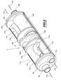
- Figure 1 is a perspective view of part of the line dual flow exhaust including catalytic converter and treatment acoustic.
- FIG. 2 is an exploded perspective view of the catalytic converter and acoustic treatment according to a first embodiment.
- FIG. 3 is a view in longitudinal section of the catalytic converter and acoustic treatment according to a second embodiment.
- Figure 4 is a perspective view of an end cover of the pot shown in one of Figures 2 and 3.
- Figure 5 is a perspective view of a holding cup a catalyst and a silencer in the envelope of the pot and guiding gas flow.
- Figure 6 is a perspective view of a cup constituting a partition of the first and second sections of the catalytic converter.
- the dual-flow exhaust line includes two conduits 2a, 2b, connected at one of their ends (in the direction of the arrow 3) to the exhaust pipes of an internal combustion engine.
- each of the conduits 2a and 2b can be connected to three pipes exhaust of three cylinders from a cylinder line of an engine V6.
- the exhaust line 1 further comprises a catalytic converter and acoustic treatment according to the invention, designated by the reference 4.
- the conduits exhaust 2a and 2b lead into an inlet portion of the pot 4.
- Des exhaust ducts 5a and 5b connected to the outlet of the pot 4 run at parallel to a fitting 6 allowing the flows transported by the two conduits 5a and 5b in the form of a single flow opening into a terminal part 7 of the exhaust line.
- the length of the part of the dual flow exhaust line between the engine manifolds and the fitting 6 is determined, taking into account the characteristics of pot 4, to optimize the acoustic behavior of gases exhaust and engine performance.
- the pot 4 comprises a metallic external envelope 8 of generally cylindrical shape closed at its ends by a first cup 8a closing the inlet part of the casing 8 and by a second cup 8b closing the outlet part of the envelope 8.
- the cups 8a and 8b are crimped onto the end parts of the cylindrical casing 8.
- the two inlet conduits 2a and 2b pass through the cup 8a to lead to the inside of the pot 4, by means of tips 9a and 9b of cylindrical or cylindrical-frustoconical shape projecting outwards from the cup 8a.
- the conduits 5a and 5b open into the volume internal of the pot 4, by means of tips 10a and 10b of cylindro-frustoconical shape projecting outwards from the cup 8b.
- FIGS. 2 and 3 which represent the pot 4 according to the invention, in a first embodiment and in a second embodiment, respectively, the corresponding elements have been designated by the same references.
- the outer casing 8 of the pot is constituted by a cylindrical steel ferrule closed at its ends by an inlet cup 8a and an outlet cup 8b.
- the internal volume of the envelope 8 of the pot 4 is divided into a first section 11a and in a second section 11b, by a partition 12 constituted by a cup fixed inside the envelope 8, in an inclined arrangement at an angle other than 90 °, relative to the longitudinal axis of the pot 4.
- the section 11a disposed on the side of the inlet of the pot 4 is between the inlet cup 8a and the inclined cup 12.
- the second section or section outlet 11b is between the inclined cup 12 and the cup exit 8b.
- a first catalyst 14a and a first silencer 15a inside the inlet section 11a of the pot 4 are arranged inside the inlet section 11a of the pot 4 .
- a first silencer 15a inside the inlet section 11a of the pot 4 are arranged inside the inlet section 11a of the pot 4 .
- the second section 11b, or outlet section of the pot 4 contains a second catalyst 14b and a second silencer 15b (in the case of the first embodiment shown in Figure 2) or 15'b (in the case of the second embodiment shown in Figure 3).
- the first section 11a and the second section 11b of the catalytic converter are identical with regard to the mounting of the silencers and catalysts in envelope 8 and are placed in the extension of one another, in a reverse layout.
- Catalysts 14a and 14b and silencers 15a and 15b or 15'a and 15'b are held inside the casing 8, by respective cups 13a and 13b at their ends near the inlet end and the outlet end of the pot 4, respectively.
- Catalysts 14a and 14b and silencers 15a and 15b or 15'a and 15'b are also held in the casing 8, at their opposite ends at the inlet or outlet of pot 4, respectively, by spacers respective which may be constituted by cups 16a and 16b.
- Catalysts 14a and 14b and silencers 15a and 15b or 15'a and 15'b have a generally cylindrical or tubular shape and are arranged inside the casing 8 so that the first catalyst 14a and the second silencer 15b or 15'b are located in the extension one of the other in the longitudinal direction of the pot 4 along which the first circulates exhaust gas flow diagrammed by arrows 17a.
- first silencer 15a or 15'a and the second catalyst 14b are arranged in the extension of one another, in the direction longitudinal circulation of the second flow of exhaust gas shown diagrammatically by arrows 17b.
- the cups 8a, 8b, 13a, 13b and 12 can be produced by cutting and stamping of a metal flank or in mechanically welded form, by attaching and fixing by welding to a metal sidewall having a stamped peripheral part, cylindrical shaped tips or cylindrical-frustoconical, according to openings cut in the side metallic.
- the cups 8a and 8b have a cylindrical peripheral edge for connection to the casing 8, a cylindrical-frustoconical end piece 9a (or 10b) and a cylindrical end piece 9b (or 10a) which project on the same side of the cup wall.
- the cups 13a and 13b have an outer peripheral edge of cylindrical shape for fixing the cup on the inner surface of the casing 8, a cylindrical-frustoconical end piece 18a (or 19b) and a tip cylindrical 18b (or 19a) projecting on either side of the wall of the cup.
- the cup 12 has an elliptical wall and, around its wall, a peripheral edge having the shape of a cylinder section between two planes inclined with respect to to the cylinder axis, through which the cup 12 can be fixed inside the cylindrical casing 8 of the pot 4, in an arrangement inclined relative to the axis of the cylindrical casing 8, at a different angle 90 °.
- the cup 12 has two end caps cylindrical-frustoconical 20a and 20b projecting on either side of the wall of the cup 12.
- the cups 16a and 16b serving as spacers for maintaining the catalysts and silencers each have a peripheral edge of attachment to the inner surface of the casing 8, an opening and a nozzle of engagement and maintenance of a catalyst and an opening and a tip for engaging and holding a silencer.
- Catalysts 14a and 14b each consist of a catalyst body substantially cylindrical with channels covered with precious metal with catalytic functions and a metal shell cylindrical surrounding the lateral surface of the catalyst body.
- One of the end faces of the catalyst body constitutes a face inlet and opposite side an outlet side of the gases passing through the catalyst in its axial direction, as shown by the arrows 17a and 17b.
- the cup 13a or 13b for holding the inlet end or the outlet end of the catalyst 14a or 14b, respectively has a tapered end piece 18a or 19b which is arranged inside the end piece frustoconical 9a or 10b of the end cup 8a or 8b (with a certain spacing) and which also receives the end of the inlet duct 2a of the first flow line or the outlet conduit 5b of the second line of stream, respectively.
- the first flow 17a of exhaust gas enters in the catalyst 14a by its entry face, being guided by the nozzle frustoconical 18a.
- the second exhaust gas flow 17b leaves the second catalyst 14b by the outlet face of the catalyst being guided by the frustoconical end 19b of the cup 13b, to reach the conduit 5b outlet which is engaged in the cylindrical end of the nozzle 19b.
- the frustoconical ends 9a and 18a on the one hand and 10b and 19b on the other hand, which are placed one inside the other with a certain spacing, constitute a double wall surrounding the gas inlet or outlet first or second flow exhaust.
- the double wall thus formed insulates the first flow or the second gas flow exhaust on entering or leaving the catalytic converter 4.
- the frustoconical tips 18a and 19b of guidance of the exhaust gases at their entry or exit can be made in one piece with the corresponding cups 13a and 13b, in a stamping or independently formed manufacturing process and attached to the cups 13a and 13b at the level of the openings having a diameter substantially equal to the outside diameter of the catalyst. It is also possible to provide end caps 18a and 18b of form frustoconical formed by an end portion of the cylindrical envelope external of catalysts 14a and 14b.
- the silencers 15a and 15b consist of a cylindrical body on which is placed in derivation, piping, respectively 21a and 21b opening into the internal space of section 11a or 11b of the casing 8 of the pot 4 which constitutes a volume depreciation.
- the bypass piping 21a of the silencer 15a is connected to the outlet part of the body of the silencer 15a placed in the first section 11a and the pipe 21b of the silencer 15b is fixed to the part of the main body of the silencer 15b placed in the second section 11b of pot 4.
- the volume of acoustic damping consists of the volume of the section 11a (or 11b) formed around the catalyst 14a (or 14b) and the corresponding silencer body 15a (or 15b) which do not fill all the internal space of the first and second sections from pot 4.
- the silencer constitutes a resonator.
- the first 15'a muffler and the second 15'b muffler consist of a tubular body whose wall is traversed by a plurality of circular openings 22a (or 22b).
- the openings 22a or 22b put in communication the internal space of the tubular body of the silencer in which the second circulates or the first exhaust gas flow, with the part of the internal volume of the first section 11a or of the second section 11b of the casing 8 of the pot 4, outside the catalyst 14a (or 14b) and the corresponding silencer.
- This part of the internal space of the first or second section of the pot 4 constitutes an acoustic damping volume.
- the catalysts and the bodies of the silencers are engaged by their end parts respectively opposite to their entry part or to their outlet part, in openings and ends of the holding cups 16a and 16b.
- the outlet end portion of the tubular body of the muffler 15'a and the inlet part of the tubular body of the silencer 15'b are engaged and crimped in the respective frustoconical ends 20b and 20a of the cup 12 separating the sections 11a and 11b from the pot 4.
- the exhaust gases from the first gas flow 17a are received in a collector whose volume expansion results from the inclination of the cup 12 and the presence of the frustoconical end piece 20a, then penetrate inside the body of the silencer 15b (or 15'b).
- the exhaust gases from the second gas flow 17b penetrate, at the outlet of the body of the silencer 15a (or 15'a) in a collector, before entering the second catalyst 14b.
- the entry end of the tubular body of the first muffler (15a, 15'a) is engaged directly on the end of the inlet pipe (2b) of the second gas flow (17b) in the pot (4) and the outlet end of the body tubular second silencer (15b, 15'b) is engaged directly on the outlet pipe (5a) of the first gas flow (17a).
- the gases of the first flow 17a are guided so as to pass through first the first catalyst 14a then the second silencer 15b (or 15'b).
- the gases of the second exhaust gas flow 17b pass successively the first silencer 15a (or 15'a) and the second catalyst 14b.
- the first exhaust stream undergoes inside the pot 4 a treatment for removing pollutants and an acoustic treatment, following a sequence reversed with respect to the second stream.
- the pot 4 In order to improve the conditions for the elimination treatment of pollutants in contact with the catalysts, it may be advantageous to place the pot 4 as close as possible to the exhaust gas outlet pipes of the motor, which can be easily achieved due to the compactness of the pot 4 and also due to the fact that pot 4 is double flow and that at the outlet of pot 4, the exhaust gases are also taken up by two conduits running in parallel.
- Optimizing acoustic chords allows gain engine torque, in particular in the vicinity of the speeds for which a decrease in the torque is observed, that is to say in the vicinity of 2000 and 3000 rpm.
- the pot 4 according to the invention makes it possible to carry out a treatment very effective attenuation acoustics for exhaust gas flows.
- the entry and exit cones exhaust gas outlet in the catalysts are double walled, this which limits the emission of noise from exhaust gas flows.
- catalysts 14a and 14b which are located entirely at inside the metal casing 8 of the pot 4, are protected against thermal shock or corrosive attack that occurs when the metal shell of the catalyst is likely to come into direct contact with the external environment in which the motor vehicle circulates. This therefore increases the strength of the metal casings of the catalysts.
- the device according to the invention brings together in a small volume the components required for anti-pollutant treatment and treatment acoustics of exhaust gas flows.
- the catalytic converter and acoustic treatment according to the invention can be carried out with a number of stamped and welded parts reduced, compared to an exhaust line classic. This gives a very good price-performance ratio during manufacture of the pot according to the invention. We also get a weight gain of 10 to 15%, for the entire exhaust line, compared to one line classic dual flow exhaust.
- the end cups and internal cups for holding the catalysts and silencers can be made in a different form.
- the silencers can be of any type.
- catalytic converter and acoustic treatment according to the invention can be used on any type of motor vehicle with a line dual flow exhaust.
Applications Claiming Priority (2)
| Application Number | Priority Date | Filing Date | Title |
|---|---|---|---|
| FR9805419 | 1998-04-29 | ||
| FR9805419A FR2778207B1 (fr) | 1998-04-29 | 1998-04-29 | Pot catalytique et de traitement acoustique d'une ligne d'echappement a double flux |
Publications (1)
| Publication Number | Publication Date |
|---|---|
| EP0953741A1 true EP0953741A1 (de) | 1999-11-03 |
Family
ID=9525844
Family Applications (1)
| Application Number | Title | Priority Date | Filing Date |
|---|---|---|---|
| EP99400644A Withdrawn EP0953741A1 (de) | 1998-04-29 | 1999-03-16 | Katalysator und Schallbehandlungsgerät einer Auspuffleitung mit Doppelströmung |
Country Status (2)
| Country | Link |
|---|---|
| EP (1) | EP0953741A1 (de) |
| FR (1) | FR2778207B1 (de) |
Cited By (8)
| Publication number | Priority date | Publication date | Assignee | Title |
|---|---|---|---|---|
| FR2826301A1 (fr) * | 2001-06-20 | 2002-12-27 | Faurecia Sys Echappement | Procede de fabrication d'un element etage d'une ligne d'echappement et element etage obtenu |
| EP1541823A2 (de) * | 2003-12-09 | 2005-06-15 | J. Eberspächer GmbH & Co. KG | Schalldämpfer für eine Abgasanlage |
| EP2116699A1 (de) * | 2008-05-05 | 2009-11-11 | J. Eberspächer GmbH Co. KG | Abgasbehandlungseinrichtung |
| DE112008001343B4 (de) * | 2007-05-21 | 2012-06-06 | Toyota Jidosha Kabushiki Kaisha | Ausströmrohr für einen am Fahrzeug montierten Motor |
| JP2013155729A (ja) * | 2012-01-27 | 2013-08-15 | Daihatsu Diesel Mfg Co Ltd | 排ガス浄化装置 |
| US8763375B2 (en) | 2010-08-19 | 2014-07-01 | J. Eberspaecher Gmbh & Co. Kg | Exhaust gas cleaning device, exhaust system, removal method |
| US9222392B2 (en) | 2010-04-15 | 2015-12-29 | Eberspaecher Exhaust Technology Gmbh & Co. Kg | Exhaust gas treatment device |
| DE112006004272B4 (de) * | 2005-12-16 | 2016-03-24 | Cummins Filtration Ip, Inc. | Mehrstromfiltersystem |
Citations (4)
| Publication number | Priority date | Publication date | Assignee | Title |
|---|---|---|---|---|
| JPS5893921A (ja) * | 1981-11-30 | 1983-06-03 | Nippon Radiator Co Ltd | 排気装置 |
| US4625511A (en) * | 1984-08-13 | 1986-12-02 | Arvin Industries, Inc. | Exhaust processor |
| US5009065A (en) * | 1988-08-15 | 1991-04-23 | Arvin Industries, Inc. | Tuned exhaust processor assembly |
| JPH0419319A (ja) * | 1990-05-09 | 1992-01-23 | Sango:Kk | 内燃機関のデュアル排気系における消音装置 |
-
1998
- 1998-04-29 FR FR9805419A patent/FR2778207B1/fr not_active Expired - Fee Related
-
1999
- 1999-03-16 EP EP99400644A patent/EP0953741A1/de not_active Withdrawn
Patent Citations (4)
| Publication number | Priority date | Publication date | Assignee | Title |
|---|---|---|---|---|
| JPS5893921A (ja) * | 1981-11-30 | 1983-06-03 | Nippon Radiator Co Ltd | 排気装置 |
| US4625511A (en) * | 1984-08-13 | 1986-12-02 | Arvin Industries, Inc. | Exhaust processor |
| US5009065A (en) * | 1988-08-15 | 1991-04-23 | Arvin Industries, Inc. | Tuned exhaust processor assembly |
| JPH0419319A (ja) * | 1990-05-09 | 1992-01-23 | Sango:Kk | 内燃機関のデュアル排気系における消音装置 |
Non-Patent Citations (2)
| Title |
|---|
| PATENT ABSTRACTS OF JAPAN vol. 007, no. 193 (M - 238) 24 August 1983 (1983-08-24) * |
| PATENT ABSTRACTS OF JAPAN vol. 016, no. 181 (M - 1242) 30 April 1992 (1992-04-30) * |
Cited By (13)
| Publication number | Priority date | Publication date | Assignee | Title |
|---|---|---|---|---|
| FR2826301A1 (fr) * | 2001-06-20 | 2002-12-27 | Faurecia Sys Echappement | Procede de fabrication d'un element etage d'une ligne d'echappement et element etage obtenu |
| WO2003002281A1 (fr) * | 2001-06-20 | 2003-01-09 | Faurecia Systemes D'echappement | Procede de fabrication d'un element etage d'une ligne d'echappement et element etage obtenu |
| EP1541823A2 (de) * | 2003-12-09 | 2005-06-15 | J. Eberspächer GmbH & Co. KG | Schalldämpfer für eine Abgasanlage |
| EP1541823A3 (de) * | 2003-12-09 | 2006-03-15 | J. Eberspächer GmbH & Co. KG | Schalldämpfer für eine Abgasanlage |
| DE112006004272B4 (de) * | 2005-12-16 | 2016-03-24 | Cummins Filtration Ip, Inc. | Mehrstromfiltersystem |
| US8327633B2 (en) | 2007-05-21 | 2012-12-11 | Toyota Jidosha Kabushiki Kaisha | Exhaust pipe for vehicle-mounted engine |
| DE112008001343B4 (de) * | 2007-05-21 | 2012-06-06 | Toyota Jidosha Kabushiki Kaisha | Ausströmrohr für einen am Fahrzeug montierten Motor |
| US8336301B2 (en) | 2008-05-05 | 2012-12-25 | J. Eberspaecher Gmbh & Co. Kg | Exhaust gas treatment unit |
| EP2116699A1 (de) * | 2008-05-05 | 2009-11-11 | J. Eberspächer GmbH Co. KG | Abgasbehandlungseinrichtung |
| US9222392B2 (en) | 2010-04-15 | 2015-12-29 | Eberspaecher Exhaust Technology Gmbh & Co. Kg | Exhaust gas treatment device |
| US8763375B2 (en) | 2010-08-19 | 2014-07-01 | J. Eberspaecher Gmbh & Co. Kg | Exhaust gas cleaning device, exhaust system, removal method |
| JP2013155729A (ja) * | 2012-01-27 | 2013-08-15 | Daihatsu Diesel Mfg Co Ltd | 排ガス浄化装置 |
| JP2013155727A (ja) * | 2012-01-27 | 2013-08-15 | Daihatsu Diesel Mfg Co Ltd | 排ガス浄化システムおよび排ガス浄化装置 |
Also Published As
| Publication number | Publication date |
|---|---|
| FR2778207B1 (fr) | 2000-07-28 |
| FR2778207A1 (fr) | 1999-11-05 |
Similar Documents
| Publication | Publication Date | Title |
|---|---|---|
| EP0057623B1 (de) | Abgassschalldämpfer einer Wärmekraftmaschine | |
| FR2620169A1 (fr) | Partie de ligne d'echappement, notamment pour moteur a combustion interne | |
| EP3118430B1 (de) | Austrittskammer mit einer hauptummantelung und einer teilummantelung, herstellungsverfahren einer solchen kammer | |
| US20070151798A1 (en) | Muffler for a motorcycle | |
| EP0395540A1 (de) | Modularer Schalldämpfer | |
| EP0953741A1 (de) | Katalysator und Schallbehandlungsgerät einer Auspuffleitung mit Doppelströmung | |
| EP1559877B1 (de) | Schalldämpfer für Abgasleitung eines Kraftfahrzeugmotors und Verfahren zur Montage | |
| US20040178016A1 (en) | Exhaust silencer for internal combustion engine | |
| WO2012172201A1 (fr) | Enveloppe coudee d'un ensemble de post-traitement des gaz d'echappement d'un moteur a combustion comportant deux demi-coquilles | |
| EP0243559B1 (de) | Schalldämpfer für Gasstrom | |
| EP2678536B1 (de) | Kraftfahrzeug beinhaltend eine abgasanlage wobei die akustische vorrichtung vor dem hinteradantrieb angeordnet ist | |
| FR2527684A1 (fr) | Systeme d'echappement pour automobile | |
| US20190292955A1 (en) | Method of providing a leak free acoustic volume for a vehicle frame member | |
| FR3080428A1 (fr) | Vanne pilotee pour ligne d'echappement et procede de fabrication correspondant | |
| WO2006061489A1 (fr) | Volume d'echappement | |
| EP0806554A1 (de) | Auspuffanlage für Brennkraftmaschine | |
| WO1997005370A1 (fr) | Dispositif d'echappement pour moteur a combustion interne | |
| EP3039257B1 (de) | Schalldämpfer für eine abgasleitung einer wärmekraftmaschine | |
| FR2951495A1 (fr) | Volume d'echappement muni d'une paroi poreuse d'absorption acoustique. | |
| EP0072274B1 (de) | Reaktiver Schalldämpfer für pulsierenden Gasstrom | |
| WO2004097191A2 (fr) | Organe de la ligne d’echappement d’un vehicule automobile | |
| EP3014081B1 (de) | Schalldämpfer zur montage im abgasstrang eines verbrennungsmotors | |
| FR2467974A1 (fr) | Silencieux plus specialement pour moteurs de vehicules | |
| FR3106853A1 (fr) | Dispositif d’echappement comprenant des bossages de maintien d’un boitier de depollution | |
| FR2583819A1 (fr) | Silencieux d'echappement en particulier pour motocyclettes a moteur a quatre cylindres et quatre temps |
Legal Events
| Date | Code | Title | Description |
|---|---|---|---|
| PUAI | Public reference made under article 153(3) epc to a published international application that has entered the european phase |
Free format text: ORIGINAL CODE: 0009012 |
|
| AK | Designated contracting states |
Kind code of ref document: A1 Designated state(s): CH DE ES GB IT LI PT SE |
|
| AX | Request for extension of the european patent |
Free format text: AL;LT;LV;MK;RO;SI |
|
| 17P | Request for examination filed |
Effective date: 20000418 |
|
| AKX | Designation fees paid |
Free format text: CH DE ES GB IT LI PT SE |
|
| 17Q | First examination report despatched |
Effective date: 20010612 |
|
| STAA | Information on the status of an ep patent application or granted ep patent |
Free format text: STATUS: THE APPLICATION HAS BEEN WITHDRAWN |
|
| 18W | Application withdrawn |
Withdrawal date: 20011102 |