EP2116205B1 - Implant en forme de tige, en particulier pour la stabilisation dynamique de la colonne vertébrale - Google Patents
Implant en forme de tige, en particulier pour la stabilisation dynamique de la colonne vertébrale Download PDFInfo
- Publication number
- EP2116205B1 EP2116205B1 EP20080008529 EP08008529A EP2116205B1 EP 2116205 B1 EP2116205 B1 EP 2116205B1 EP 20080008529 EP20080008529 EP 20080008529 EP 08008529 A EP08008529 A EP 08008529A EP 2116205 B1 EP2116205 B1 EP 2116205B1
- Authority
- EP
- European Patent Office
- Prior art keywords
- rod
- shaped implant
- shaped
- flexible
- helices
- Prior art date
- Legal status (The legal status is an assumption and is not a legal conclusion. Google has not performed a legal analysis and makes no representation as to the accuracy of the status listed.)
- Not-in-force
Links
Images


Classifications
-
- A—HUMAN NECESSITIES
- A61—MEDICAL OR VETERINARY SCIENCE; HYGIENE
- A61B—DIAGNOSIS; SURGERY; IDENTIFICATION
- A61B17/00—Surgical instruments, devices or methods, e.g. tourniquets
- A61B17/56—Surgical instruments or methods for treatment of bones or joints; Devices specially adapted therefor
- A61B17/58—Surgical instruments or methods for treatment of bones or joints; Devices specially adapted therefor for osteosynthesis, e.g. bone plates, screws, setting implements or the like
- A61B17/68—Internal fixation devices, including fasteners and spinal fixators, even if a part thereof projects from the skin
- A61B17/70—Spinal positioners or stabilisers ; Bone stabilisers comprising fluid filler in an implant
- A61B17/7001—Screws or hooks combined with longitudinal elements which do not contact vertebrae
- A61B17/7002—Longitudinal elements, e.g. rods
- A61B17/7019—Longitudinal elements having flexible parts, or parts connected together, such that after implantation the elements can move relative to each other
- A61B17/7026—Longitudinal elements having flexible parts, or parts connected together, such that after implantation the elements can move relative to each other with a part that is flexible due to its form
- A61B17/7029—Longitudinal elements having flexible parts, or parts connected together, such that after implantation the elements can move relative to each other with a part that is flexible due to its form the entire longitudinal element being flexible
-
- A—HUMAN NECESSITIES
- A61—MEDICAL OR VETERINARY SCIENCE; HYGIENE
- A61B—DIAGNOSIS; SURGERY; IDENTIFICATION
- A61B17/00—Surgical instruments, devices or methods, e.g. tourniquets
- A61B17/56—Surgical instruments or methods for treatment of bones or joints; Devices specially adapted therefor
- A61B17/58—Surgical instruments or methods for treatment of bones or joints; Devices specially adapted therefor for osteosynthesis, e.g. bone plates, screws, setting implements or the like
- A61B17/68—Internal fixation devices, including fasteners and spinal fixators, even if a part thereof projects from the skin
- A61B17/70—Spinal positioners or stabilisers ; Bone stabilisers comprising fluid filler in an implant
- A61B17/7001—Screws or hooks combined with longitudinal elements which do not contact vertebrae
- A61B17/7002—Longitudinal elements, e.g. rods
- A61B17/7019—Longitudinal elements having flexible parts, or parts connected together, such that after implantation the elements can move relative to each other
- A61B17/7031—Longitudinal elements having flexible parts, or parts connected together, such that after implantation the elements can move relative to each other made wholly or partly of flexible material
-
- A—HUMAN NECESSITIES
- A61—MEDICAL OR VETERINARY SCIENCE; HYGIENE
- A61B—DIAGNOSIS; SURGERY; IDENTIFICATION
- A61B17/00—Surgical instruments, devices or methods, e.g. tourniquets
- A61B17/56—Surgical instruments or methods for treatment of bones or joints; Devices specially adapted therefor
- A61B17/58—Surgical instruments or methods for treatment of bones or joints; Devices specially adapted therefor for osteosynthesis, e.g. bone plates, screws, setting implements or the like
- A61B17/68—Internal fixation devices, including fasteners and spinal fixators, even if a part thereof projects from the skin
- A61B17/70—Spinal positioners or stabilisers ; Bone stabilisers comprising fluid filler in an implant
- A61B17/7001—Screws or hooks combined with longitudinal elements which do not contact vertebrae
- A61B17/7002—Longitudinal elements, e.g. rods
- A61B17/7019—Longitudinal elements having flexible parts, or parts connected together, such that after implantation the elements can move relative to each other
- A61B17/7026—Longitudinal elements having flexible parts, or parts connected together, such that after implantation the elements can move relative to each other with a part that is flexible due to its form
- A61B17/7028—Longitudinal elements having flexible parts, or parts connected together, such that after implantation the elements can move relative to each other with a part that is flexible due to its form the flexible part being a coil spring
-
- A—HUMAN NECESSITIES
- A61—MEDICAL OR VETERINARY SCIENCE; HYGIENE
- A61B—DIAGNOSIS; SURGERY; IDENTIFICATION
- A61B17/00—Surgical instruments, devices or methods, e.g. tourniquets
- A61B17/56—Surgical instruments or methods for treatment of bones or joints; Devices specially adapted therefor
- A61B17/58—Surgical instruments or methods for treatment of bones or joints; Devices specially adapted therefor for osteosynthesis, e.g. bone plates, screws, setting implements or the like
- A61B17/68—Internal fixation devices, including fasteners and spinal fixators, even if a part thereof projects from the skin
- A61B17/70—Spinal positioners or stabilisers ; Bone stabilisers comprising fluid filler in an implant
- A61B17/7001—Screws or hooks combined with longitudinal elements which do not contact vertebrae
- A61B17/7032—Screws or hooks with U-shaped head or back through which longitudinal rods pass
-
- A—HUMAN NECESSITIES
- A61—MEDICAL OR VETERINARY SCIENCE; HYGIENE
- A61B—DIAGNOSIS; SURGERY; IDENTIFICATION
- A61B17/00—Surgical instruments, devices or methods, e.g. tourniquets
- A61B17/56—Surgical instruments or methods for treatment of bones or joints; Devices specially adapted therefor
- A61B17/58—Surgical instruments or methods for treatment of bones or joints; Devices specially adapted therefor for osteosynthesis, e.g. bone plates, screws, setting implements or the like
- A61B17/68—Internal fixation devices, including fasteners and spinal fixators, even if a part thereof projects from the skin
- A61B17/70—Spinal positioners or stabilisers ; Bone stabilisers comprising fluid filler in an implant
- A61B17/7001—Screws or hooks combined with longitudinal elements which do not contact vertebrae
- A61B17/7035—Screws or hooks, wherein a rod-clamping part and a bone-anchoring part can pivot relative to each other
- A61B17/7037—Screws or hooks, wherein a rod-clamping part and a bone-anchoring part can pivot relative to each other wherein pivoting is blocked when the rod is clamped
Definitions
- the invention relates to a rod-shaped implant, in particular for the dynamic stabilization of the spine.
- the rod-shaped implant comprises at least a portion which is made of a flexible first material forming a matrix in which a flexible structure comprising at least one fiber made of a second material is embedded.
- a rod-shaped implant made of a plastic material for the dynamic stabilization of the spinal column is known, for example, from US 2007/0093820 A1 , US 2007/0161999 A1 and US 2007/0270843 A1 .
- US 2006/0142758 A1 describes a linking element for a spinal fixing system which consists at least partly of a support made of polymeric material and a rod, bent or not, substantially coaxial with the support.
- the rod is, for example, made of a helical spring having an axis and turns which are at least partly embedded in the support made of polymer material.
- the helical spring is, for example, made of a metal or a metal alloy.
- the structure of the linking element permits compression and distraction in order to permit a dynamic stabilization of the spine.
- US 2007/270821v A1 discloses a rod-shaped implant, in particular for the dynamic stabilization of the spine, at least a portion of which is comprised of a flexible first material forming a matrix in which a flexible structure comprising at least one fiber made of a second material is embedded.
- the rod-shaped implant according to the invention has a flexibility which is dependent on the direction of the force acting between the vertebrae stabilized by the implant. It exhibits a particularly stiff behavior when a torsional force acts onto the rod while it allows an axial compression or extension when an axial compression or tension force acts onto the implant, respectively.
- the flexible properties of the rod-shaped implant can be designed specifically according to the clinical requirements by selecting an appropriate flexible structure which is formed by fibers.
- Figs. 1 to 3 show the rod-shaped implant according to a first embodiment in a schematic side view, a cross sectional view and a perspective view.
- the rod-shaped implant 1 is substantially cylindrical in shape with an outer diameter D. It is composed of a flexible structure 2 which is embedded into a matrix of polymeric material 3.
- the polymeric material exhibits flexibility and is preferably an elastomer. Examples for a suitable elastomer material are biocompatible polyurethanes or polycarbonate urethane (PCU).
- the outer diameter D of the rod-shaped implant is designed such that the rod-shaped implant can be fixed in receiving parts of pedicle screws, for example.
- the flexibility of the polymeric material is usually isotropic.
- the flexible structure 2 is provided.
- the flexible structure 2 according to the first embodiment comprises an inner structure 2a and an outer structure 2b.
- the inner structure 2a comprises four helices 2a1, 2a2, 2a3 and 2a4 which are arranged coaxially to the longitudinal axis L of the rod-shaped implant.
- the inner structure 2a has a first diameter d 1 which is the same for all four helices.
- the helices 2a1 to 2a4 are rotated with respect to each other by 90°.
- the first inner structure 2a thereby forms a hollow cylindrical web-like structure.
- the outer structure 2b similarly comprises four helices 2b1, 2b2, 2b3 and 2b4 which are also arranged coaxially to the longitudinal axis L and are rotated with respect to each other by 90°.
- the diameter d 2 of the helices of the outer structure is larger than the diameter d 1 of the helices of the inner structure but smaller than the outer diameter D of the rod-shaped implant 1.
- the outer structure 2b is rotated with respect to the inner structure 2a by 180°.
- the outer structure 2b also forms a hollow cylindrical net-like or web-like structure.
- the outer structure 2b encompasses the inner structure 2a in the rod-shaped implant.
- the helices are made of fibers that have a high strength in the direction in which the fiber extends.
- the spring-like properties like the tensile strength and the compression strength of the fiber is defined by the geometry of the fibers.
- the distance and number of windings of the helices, the thickness of the fibers as well as the diameters d 1 and d 2 define the flexible characteristics of the helices and therefore of the whole flexible structure 2.
- the material of the fibers is preferably a polymer for example polypropylene or a similar material. However, carbon or kevlar fibers may also be used.
- the material can be the same for the helices of the inner structure and the outer structure or can be different to provide specific properties.
- the difference between the elastic modulus of the fibers and that of the polymer matrix is less than between a metal spring and the polymer matrix. Therefore the risk of loosening of the fibers within the polymer matrix during load is small or does not exist.
- the rod-shaped implant I is manufactured, for example, by first assembling the inner structure and the outer structure and then injection molding the polymer matrix around the whole flexible structure 2 so that the flexible structure 2 is embedded in the polymer matrix 3.
- Figs. 7 to 9 show the fixation of the rod-shaped implant in a monoaxial pedicle screw.
- the pedicle screw 5 comprises a threaded shank 6 and a receiving part 7 formed at one end of the threaded shank 6.
- the receiving part 7 is substantially cylindrical and comprises a U-shaped recess 8 extending from the free end in the direction of the threaded shank thereby forming two free legs on which an inner thread 9 is provided.
- an engagement structure 10 in form of ribs extending transversely to the longitudinal axis L of the rod-shaped implant are provided.
- a fixation screw 11 is provided which can be screwed into the inner thread 9 of the receiving part 7.
- the fixation screw 11 comprises an engagement structure 12 at its side facing the U-shaped implant 1 which can be, as shown in Figs. 8 and 9 , a ring-shaped projection.
- At least two pedicle screws 5 are screwed in to adjacent vertebrae and the rod-shaped implant 1 is inserted and fixed by the fixation screw.
- the engagement structure 10 of the receiving part and the engagement structure 12 of the fixation screw press onto the rod-shaped implant 1, thereby deforming the surface of the polymer matrix 3 in such a way that a partially form-fit connection is generated between the engagement structure and the polymer matrix which holds the rod-shaped implant safe in place.
- the dimensions of the engagement structures are designed such that the flexible structure of the rod-shaped implant I is not deformed when tightening the fixation screw 11.
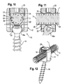
- Figs. 10 to 12 show the fixation of the rod-shaped implant in a polyaxial pedicle screw.
- the polyaxial pedicle screw 15 comprises a screw member 16 with a threaded shank and a spherically-shaped head 16a and a receiving part 17.
- the receiving part 17 is substantially cylindrical and comprises a U-shaped recess 18 and a coaxial bore 19 which tapers into an opening 20 in which the head 16a of the screw member 16a is held so that it can pivot with respect to the receiving part 17.
- a pressure member 22 is provided by means of which pressure can be exerted onto the head 16a to fix the head 16a.
- the pressure member 22 can be inserted into the bore 19 and is designed to receive the rod-shaped implant 1.
- a fixation screw 23 is provided which comprises an engagement structure 24 at its side facing the rod-shaped implant 1.
- At least two pedicle screws are screwed into adjacent vertebrae, the receiving parts 17 are aligned to receive the rod-shaped implant which is then fixed by the fixation screw 23.
- the head 16a is fixed in its position.
- the rod-shaped implant is fixed in the receiving part.
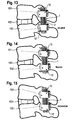
- Figs. 13 to 15 show the rod-shaped implant I fixed to two polyaxial pedicle screws 15, 15' anchored in the pedicles of adjacent vertebrae 101, 102 enclosing an intervertebral disk 103 between each other.
- Fig. 13 shows the neutral position. In this position the flexible structure 2 and the polymer matrix of the rod-shaped implant are neither compressed nor extended.
- Fig. 14 shows the condition of flexion of the spine wherein the distance of the pedicles and hence of the pedicle screws become larger than in the neutral position. The tensile force acting onto the rod-shaped implant causes the inner and the outer structures 2a, 2b to extend together with the surrounding polymer matrix.
- Fig. 13 to 15 show the rod-shaped implant I fixed to two polyaxial pedicle screws 15, 15' anchored in the pedicles of adjacent vertebrae 101, 102 enclosing an intervertebral disk 103 between each other.
- Fig. 13 shows the neutral position. In this position the flexible structure 2 and the polymer matrix
- Fig. 16 shows the length of the rod-shaped implant schematically in the neutral position and Fig. 17 shows the compression and shortening of the length of the rod-shaped implant.
- a torsional force F acts around the longitudinal axis of the rod-shaped implant as shown in Fig. 18 the flexible structure 2 withstands this torsional force so that a twisting of the rod-shaped implant does practically not occur. Since the inner structure and the outer structure are rotated against each other by 180° a high torsional stiffness can be provided.
- the torsional stiffness of the rod-shaped implant can be designed specifically by selecting the flexible properties of the flexible structure.
- Figs. 19a to 19c show a second embodiment of the flexible structure of the rod-shaped implant. It differs from the first embodiment shown in Figs. 1 to 18 in that the outer structure has the same diameter than the inner structure.
- the inner and outer helices are connected in a net or web structure.
- Figs. 20a and 20b show a further modification of the flexible structure.
- the flexible structure consists on one single inner helix 2a' and one single outer helix 2b' having a larger diameter than that of the inner helix and being rotated by 180° with respect to the inner helix.
- the pitch of the windings of the helices can vary within one single helix or between different helices.
- the flexible structure must not necessarily be composed of helices. It can also be another net or web structure made of fibers, for example a fabric-like structure with diamond shaped openings or any other net or web structure which allows extension and compression while providing rotational stiffness.
Claims (11)
- Implant en forme de tige, en particulier pour la stabilisation dynamique de la colonne vertébrale,
dont au moins une partie se compose d'un premier matériau souple formant une matrice (3) dans laquelle une structure souple (2) comprenant au moins une fibre réalisée en un deuxième matériau est intégrée, caractérisé en ce que
la structure souple (2) comprend une structure coaxiale interne (2a) en forme de filet et une structure coaxiale externe (2b) en forme de filet agencée autour de la structure interne. - Implant en forme de tige de la revendication 1, dans lequel le premier matériau est un polymère, en particulier un matériau élastomère.
- Implant en forme de tige de la revendication 1 ou 2, dans lequel le deuxième matériau est un matériau synthétique, en particulier le polypropylène.
- Implant en forme de tige de l'une des revendications 1 à 3, dans lequel la structure souple (2) se compose d'au moins deux fibres en forme d'hélice rotatives l'une par rapport à l'autre par un angle.
- Implant en forme de tige de la revendication 4, dans lequel l'angle est de 180°.
- Implant en forme de tige de la revendication 4 ou 5, dans lequel les fibres en forme d'hélice ont le même diamètre.
- Implant en forme de tige de la revendication 4 ou 5, dans lequel les fibres en forme d'hélice ont différents diamètres.
- Implant en forme de tige selon l'une des revendications 1 à 7, dans lequel la structure souple (2) est une structure en forme de filet qui améliore la rigidité en torsion de l'implant (1) en forme de tige.
- Implant en forme de tige selon l'une des revendications 1 à 8, dans lequel la structure interne (2a) comprend quatre hélices (2a1, 2a2, 2a3, 2a4) et la structure externe (2b) comprend quatre hélices (2b1, 2b2, 2b3, 2b4).
- Implant en forme de tige selon l'une des revendications 1 à 9 de la revendication 9 ou 10, dans lequel les hélices de la structure interne sont rotatives les unes par rapport aux autres par 90° et les hélices de la structure externe sont rotatives les unes par rapport aux autres par 90°.
- Implant en forme de tige selon l'une des revendications 1 à 10, dans lequel la structure interne (2a) et la structure externe (2b) sont rotatives l'une par rapport à l'autre par 180°.
Priority Applications (9)
| Application Number | Priority Date | Filing Date | Title |
|---|---|---|---|
| ES08008529T ES2358718T3 (es) | 2008-05-06 | 2008-05-06 | Implante en forma de varilla, en concreto para la estabilización dinámica de la columna vertebral. |
| EP20080008529 EP2116205B1 (fr) | 2008-05-06 | 2008-05-06 | Implant en forme de tige, en particulier pour la stabilisation dynamique de la colonne vertébrale |
| EP10016134A EP2298199B1 (fr) | 2008-05-06 | 2008-05-06 | Implant en forme de tige, en particulier pour la stabilisation dynamique de la colonne vertébrale |
| DE200860004213 DE602008004213D1 (de) | 2008-05-06 | 2008-05-06 | Stangenförmiges Implantat, insbesondere zur dynamischen Stabilisierung der Wirbelsäule |
| CN200910132270.7A CN101574278B (zh) | 2008-05-06 | 2009-04-30 | 用于脊柱的动态稳固的杆状植入物 |
| TW98114301A TWI473592B (zh) | 2008-05-06 | 2009-04-30 | 尤指脊骨動態穩定用之桿狀植入體 |
| JP2009110766A JP5485582B2 (ja) | 2008-05-06 | 2009-04-30 | ロッド形状のインプラント |
| KR1020090038203A KR101559857B1 (ko) | 2008-05-06 | 2009-04-30 | 척추의 동적인 안정성을 위한 봉 형상 임플란트 |
| US12/435,894 US9072545B2 (en) | 2008-05-06 | 2009-05-05 | Rod-shaped implant, in particular for the dynamic stabilization of the spine |
Applications Claiming Priority (1)
| Application Number | Priority Date | Filing Date | Title |
|---|---|---|---|
| EP20080008529 EP2116205B1 (fr) | 2008-05-06 | 2008-05-06 | Implant en forme de tige, en particulier pour la stabilisation dynamique de la colonne vertébrale |
Publications (2)
| Publication Number | Publication Date |
|---|---|
| EP2116205A1 EP2116205A1 (fr) | 2009-11-11 |
| EP2116205B1 true EP2116205B1 (fr) | 2010-12-29 |
Family
ID=39773139
Family Applications (2)
| Application Number | Title | Priority Date | Filing Date |
|---|---|---|---|
| EP10016134A Not-in-force EP2298199B1 (fr) | 2008-05-06 | 2008-05-06 | Implant en forme de tige, en particulier pour la stabilisation dynamique de la colonne vertébrale |
| EP20080008529 Not-in-force EP2116205B1 (fr) | 2008-05-06 | 2008-05-06 | Implant en forme de tige, en particulier pour la stabilisation dynamique de la colonne vertébrale |
Family Applications Before (1)
| Application Number | Title | Priority Date | Filing Date |
|---|---|---|---|
| EP10016134A Not-in-force EP2298199B1 (fr) | 2008-05-06 | 2008-05-06 | Implant en forme de tige, en particulier pour la stabilisation dynamique de la colonne vertébrale |
Country Status (8)
| Country | Link |
|---|---|
| US (1) | US9072545B2 (fr) |
| EP (2) | EP2298199B1 (fr) |
| JP (1) | JP5485582B2 (fr) |
| KR (1) | KR101559857B1 (fr) |
| CN (1) | CN101574278B (fr) |
| DE (1) | DE602008004213D1 (fr) |
| ES (1) | ES2358718T3 (fr) |
| TW (1) | TWI473592B (fr) |
Families Citing this family (70)
| Publication number | Priority date | Publication date | Assignee | Title |
|---|---|---|---|---|
| US7833250B2 (en) | 2004-11-10 | 2010-11-16 | Jackson Roger P | Polyaxial bone screw with helically wound capture connection |
| US7862587B2 (en) | 2004-02-27 | 2011-01-04 | Jackson Roger P | Dynamic stabilization assemblies, tool set and method |
| US10258382B2 (en) | 2007-01-18 | 2019-04-16 | Roger P. Jackson | Rod-cord dynamic connection assemblies with slidable bone anchor attachment members along the cord |
| US10729469B2 (en) | 2006-01-09 | 2020-08-04 | Roger P. Jackson | Flexible spinal stabilization assembly with spacer having off-axis core member |
| US8292926B2 (en) | 2005-09-30 | 2012-10-23 | Jackson Roger P | Dynamic stabilization connecting member with elastic core and outer sleeve |
| US8353932B2 (en) | 2005-09-30 | 2013-01-15 | Jackson Roger P | Polyaxial bone anchor assembly with one-piece closure, pressure insert and plastic elongate member |
| US8876868B2 (en) | 2002-09-06 | 2014-11-04 | Roger P. Jackson | Helical guide and advancement flange with radially loaded lip |
| US7621918B2 (en) | 2004-11-23 | 2009-11-24 | Jackson Roger P | Spinal fixation tool set and method |
| US7377923B2 (en) | 2003-05-22 | 2008-05-27 | Alphatec Spine, Inc. | Variable angle spinal screw assembly |
| US8398682B2 (en) | 2003-06-18 | 2013-03-19 | Roger P. Jackson | Polyaxial bone screw assembly |
| US8377102B2 (en) | 2003-06-18 | 2013-02-19 | Roger P. Jackson | Polyaxial bone anchor with spline capture connection and lower pressure insert |
| US7766915B2 (en) | 2004-02-27 | 2010-08-03 | Jackson Roger P | Dynamic fixation assemblies with inner core and outer coil-like member |
| US7776067B2 (en) | 2005-05-27 | 2010-08-17 | Jackson Roger P | Polyaxial bone screw with shank articulation pressure insert and method |
| US8926670B2 (en) | 2003-06-18 | 2015-01-06 | Roger P. Jackson | Polyaxial bone screw assembly |
| US8137386B2 (en) | 2003-08-28 | 2012-03-20 | Jackson Roger P | Polyaxial bone screw apparatus |
| US8814911B2 (en) | 2003-06-18 | 2014-08-26 | Roger P. Jackson | Polyaxial bone screw with cam connection and lock and release insert |
| US11419642B2 (en) | 2003-12-16 | 2022-08-23 | Medos International Sarl | Percutaneous access devices and bone anchor assemblies |
| US7179261B2 (en) | 2003-12-16 | 2007-02-20 | Depuy Spine, Inc. | Percutaneous access devices and bone anchor assemblies |
| US7527638B2 (en) | 2003-12-16 | 2009-05-05 | Depuy Spine, Inc. | Methods and devices for minimally invasive spinal fixation element placement |
| US8152810B2 (en) | 2004-11-23 | 2012-04-10 | Jackson Roger P | Spinal fixation tool set and method |
| AU2004317551B2 (en) | 2004-02-27 | 2008-12-04 | Roger P. Jackson | Orthopedic implant rod reduction tool set and method |
| US7160300B2 (en) | 2004-02-27 | 2007-01-09 | Jackson Roger P | Orthopedic implant rod reduction tool set and method |
| US8066739B2 (en) | 2004-02-27 | 2011-11-29 | Jackson Roger P | Tool system for dynamic spinal implants |
| US11241261B2 (en) | 2005-09-30 | 2022-02-08 | Roger P Jackson | Apparatus and method for soft spinal stabilization using a tensionable cord and releasable end structure |
| US7651502B2 (en) | 2004-09-24 | 2010-01-26 | Jackson Roger P | Spinal fixation tool set and method for rod reduction and fastener insertion |
| US8926672B2 (en) | 2004-11-10 | 2015-01-06 | Roger P. Jackson | Splay control closure for open bone anchor |
| CA2586361A1 (fr) | 2004-11-10 | 2006-05-18 | Roger P. Jackson | Guide helicoidal et rebord de glissement comportant des prolongements cassables |
| US9168069B2 (en) | 2009-06-15 | 2015-10-27 | Roger P. Jackson | Polyaxial bone anchor with pop-on shank and winged insert with lower skirt for engaging a friction fit retainer |
| US9393047B2 (en) | 2009-06-15 | 2016-07-19 | Roger P. Jackson | Polyaxial bone anchor with pop-on shank and friction fit retainer with low profile edge lock |
| US9980753B2 (en) | 2009-06-15 | 2018-05-29 | Roger P Jackson | pivotal anchor with snap-in-place insert having rotation blocking extensions |
| US8444681B2 (en) | 2009-06-15 | 2013-05-21 | Roger P. Jackson | Polyaxial bone anchor with pop-on shank, friction fit retainer and winged insert |
| US8308782B2 (en) | 2004-11-23 | 2012-11-13 | Jackson Roger P | Bone anchors with longitudinal connecting member engaging inserts and closures for fixation and optional angulation |
| US9216041B2 (en) | 2009-06-15 | 2015-12-22 | Roger P. Jackson | Spinal connecting members with tensioned cords and rigid sleeves for engaging compression inserts |
| WO2006057837A1 (fr) | 2004-11-23 | 2006-06-01 | Jackson Roger P | Structure d'accrochage pour outil de fixation spinale |
| US7901437B2 (en) | 2007-01-26 | 2011-03-08 | Jackson Roger P | Dynamic stabilization member with molded connection |
| US10076361B2 (en) | 2005-02-22 | 2018-09-18 | Roger P. Jackson | Polyaxial bone screw with spherical capture, compression and alignment and retention structures |
| US8105368B2 (en) | 2005-09-30 | 2012-01-31 | Jackson Roger P | Dynamic stabilization connecting member with slitted core and outer sleeve |
| US8475498B2 (en) | 2007-01-18 | 2013-07-02 | Roger P. Jackson | Dynamic stabilization connecting member with cord connection |
| US8366745B2 (en) | 2007-05-01 | 2013-02-05 | Jackson Roger P | Dynamic stabilization assembly having pre-compressed spacers with differential displacements |
| US10383660B2 (en) | 2007-05-01 | 2019-08-20 | Roger P. Jackson | Soft stabilization assemblies with pretensioned cords |
| US9232968B2 (en) | 2007-12-19 | 2016-01-12 | DePuy Synthes Products, Inc. | Polymeric pedicle rods and methods of manufacturing |
| ES2359756T3 (es) * | 2008-01-28 | 2011-05-26 | Spinelab Ag | Tornillo pedicular con dispositivo de cierre. |
| JP2012529969A (ja) | 2008-08-01 | 2012-11-29 | ロジャー・ピー・ジャクソン | スリーブ付き張力付与りコードを備える長手方向接続部材 |
| US8641734B2 (en) * | 2009-02-13 | 2014-02-04 | DePuy Synthes Products, LLC | Dual spring posterior dynamic stabilization device with elongation limiting elastomers |
| EP2757988A4 (fr) | 2009-06-15 | 2015-08-19 | Jackson Roger P | Dispositif d'ancrage osseux polyaxial doté d'une tige à enclenchement par pression et insert à ailettes à pince de compression à ajustement par friction |
| US8998959B2 (en) | 2009-06-15 | 2015-04-07 | Roger P Jackson | Polyaxial bone anchors with pop-on shank, fully constrained friction fit retainer and lock and release insert |
| US11229457B2 (en) | 2009-06-15 | 2022-01-25 | Roger P. Jackson | Pivotal bone anchor assembly with insert tool deployment |
| US9668771B2 (en) | 2009-06-15 | 2017-06-06 | Roger P Jackson | Soft stabilization assemblies with off-set connector |
| EP2279705A1 (fr) * | 2009-07-28 | 2011-02-02 | Spinelab AG | Implant de colonne vertébrale |
| AU2010303934B2 (en) | 2009-10-05 | 2014-03-27 | Roger P. Jackson | Polyaxial bone anchor with non-pivotable retainer and pop-on shank, some with friction fit |
| JP2013540468A (ja) | 2010-09-08 | 2013-11-07 | ロジャー・ピー・ジャクソン | 弾性部および非弾性部を有する動的固定化部材 |
| DE102010041264A1 (de) * | 2010-09-23 | 2012-03-29 | Aces Gmbh | Dynamische Stabilisierungseinrichtung für die Wirbelsäule |
| GB2502449A (en) | 2010-11-02 | 2013-11-27 | Roger P Jackson | Polyaxial bone anchor with pop-on shank and pivotable retainer |
| WO2012128825A1 (fr) | 2011-03-24 | 2012-09-27 | Jackson Roger P | Ancrage osseux polyaxial avec articulation composée et tige enclipsable |
| EP2574296B1 (fr) * | 2011-09-28 | 2016-03-02 | Biedermann Technologies GmbH & Co. KG | Ensemble d'ancrage d'os |
| US8911479B2 (en) | 2012-01-10 | 2014-12-16 | Roger P. Jackson | Multi-start closures for open implants |
| EP2662037B1 (fr) * | 2012-05-09 | 2023-01-11 | CoLigne AG | Connecteur iliaque, tête de raccord et système de fixation spinale |
| US8911478B2 (en) | 2012-11-21 | 2014-12-16 | Roger P. Jackson | Splay control closure for open bone anchor |
| US10058354B2 (en) | 2013-01-28 | 2018-08-28 | Roger P. Jackson | Pivotal bone anchor assembly with frictional shank head seating surfaces |
| US8852239B2 (en) | 2013-02-15 | 2014-10-07 | Roger P Jackson | Sagittal angle screw with integral shank and receiver |
| US9566092B2 (en) | 2013-10-29 | 2017-02-14 | Roger P. Jackson | Cervical bone anchor with collet retainer and outer locking sleeve |
| US9717533B2 (en) | 2013-12-12 | 2017-08-01 | Roger P. Jackson | Bone anchor closure pivot-splay control flange form guide and advancement structure |
| US9451993B2 (en) | 2014-01-09 | 2016-09-27 | Roger P. Jackson | Bi-radial pop-on cervical bone anchor |
| CN112869855A (zh) * | 2014-04-11 | 2021-06-01 | 史密夫和内修有限公司 | Dmls矫形髓内装置及制造方法 |
| US10064658B2 (en) | 2014-06-04 | 2018-09-04 | Roger P. Jackson | Polyaxial bone anchor with insert guides |
| US9597119B2 (en) | 2014-06-04 | 2017-03-21 | Roger P. Jackson | Polyaxial bone anchor with polymer sleeve |
| CN105581830B (zh) * | 2015-12-14 | 2018-10-02 | 青田县人民医院 | 一种脊柱柔性固定的器具 |
| US11020149B2 (en) * | 2018-02-28 | 2021-06-01 | Globus Medical Inc. | Scoliosis correction systems, methods, and instruments |
| EP3897414A4 (fr) | 2018-12-21 | 2022-09-28 | Paradigm Spine, LLC. | Système modulaire de stabilisation de colonne vertébrale et instruments associés |
| US20220249133A1 (en) * | 2021-02-10 | 2022-08-11 | Frank J. Schwab | Methods and devices for augmenting the spine |
Family Cites Families (23)
| Publication number | Priority date | Publication date | Assignee | Title |
|---|---|---|---|---|
| FR2844180B1 (fr) | 2002-09-11 | 2005-08-05 | Spinevision | Element de liaison pour la stabilisation dynamique d'un systeme de fixation rachidien et systeme de fixation rachidien comportant un tel element |
| US6986771B2 (en) | 2003-05-23 | 2006-01-17 | Globus Medical, Inc. | Spine stabilization system |
| JP5078355B2 (ja) | 2003-05-23 | 2012-11-21 | グローバス メディカル インコーポレイティッド | 脊椎安定化システム |
| DE10327358A1 (de) | 2003-06-16 | 2005-01-05 | Ulrich Gmbh & Co. Kg | Implantat zur Korrektur und Stabilisierung der Wirbelsäule |
| GB0316915D0 (en) * | 2003-07-18 | 2003-08-20 | Glaxo Group Ltd | Compounds |
| US7763052B2 (en) | 2003-12-05 | 2010-07-27 | N Spine, Inc. | Method and apparatus for flexible fixation of a spine |
| US20050065516A1 (en) | 2003-09-24 | 2005-03-24 | Tae-Ahn Jahng | Method and apparatus for flexible fixation of a spine |
| US20050136764A1 (en) * | 2003-12-18 | 2005-06-23 | Sherman Michael C. | Designed composite degradation for spinal implants |
| FR2867057B1 (fr) * | 2004-03-02 | 2007-06-01 | Spinevision | Element de liaison dynamique pour un systeme de fixation rachidien et systeme de fixation comprenant un tel element de liaison |
| US7833256B2 (en) * | 2004-04-16 | 2010-11-16 | Biedermann Motech Gmbh | Elastic element for the use in a stabilization device for bones and vertebrae and method for the manufacture of such elastic element |
| DE102004018621B4 (de) | 2004-04-16 | 2006-06-08 | Biedermann Motech Gmbh | Elastisches Element zur Verwendung in Stabilisierungseinrichtungen für Knochen oder Wirbel und Herstellungsverfahren für ein solches elastisches Element |
| KR100645377B1 (ko) * | 2004-09-22 | 2006-11-15 | (주)바이오스파인 | 척추경 고정장치 |
| US7905903B2 (en) | 2006-02-03 | 2011-03-15 | Biomet Sports Medicine, Llc | Method for tissue fixation |
| JP4898702B2 (ja) * | 2004-12-27 | 2012-03-21 | エヌ スパイン, インコーポレイテッド | 調節可能な脊椎安定化システム |
| US7556639B2 (en) | 2005-03-03 | 2009-07-07 | Accelerated Innovation, Llc | Methods and apparatus for vertebral stabilization using sleeved springs |
| US7699875B2 (en) | 2006-04-17 | 2010-04-20 | Applied Spine Technologies, Inc. | Spinal stabilization device with weld cap |
| CH705709B1 (de) | 2005-08-29 | 2013-05-15 | Bird Biedermann Ag | Wirbelsäulenimplantat. |
| EP1795134B1 (fr) | 2005-11-17 | 2008-08-06 | BIEDERMANN MOTECH GmbH | Vis polyaxiale pour tige flexible |
| US20070233064A1 (en) * | 2006-02-17 | 2007-10-04 | Holt Development L.L.C. | Apparatus and method for flexible spinal fixation |
| US20070270821A1 (en) * | 2006-04-28 | 2007-11-22 | Sdgi Holdings, Inc. | Vertebral stabilizer |
| EP1857065B1 (fr) | 2006-05-16 | 2010-08-25 | BIEDERMANN MOTECH GmbH | Elément longitudinal pour la chirurgie rachidienne ou d'urgence |
| US8029547B2 (en) * | 2007-01-30 | 2011-10-04 | Warsaw Orthopedic, Inc. | Dynamic spinal stabilization assembly with sliding collars |
| US20080312694A1 (en) | 2007-06-15 | 2008-12-18 | Peterman Marc M | Dynamic stabilization rod for spinal implants and methods for manufacturing the same |
-
2008
- 2008-05-06 EP EP10016134A patent/EP2298199B1/fr not_active Not-in-force
- 2008-05-06 EP EP20080008529 patent/EP2116205B1/fr not_active Not-in-force
- 2008-05-06 ES ES08008529T patent/ES2358718T3/es active Active
- 2008-05-06 DE DE200860004213 patent/DE602008004213D1/de active Active
-
2009
- 2009-04-30 TW TW98114301A patent/TWI473592B/zh not_active IP Right Cessation
- 2009-04-30 CN CN200910132270.7A patent/CN101574278B/zh not_active Expired - Fee Related
- 2009-04-30 KR KR1020090038203A patent/KR101559857B1/ko not_active IP Right Cessation
- 2009-04-30 JP JP2009110766A patent/JP5485582B2/ja not_active Expired - Fee Related
- 2009-05-05 US US12/435,894 patent/US9072545B2/en not_active Expired - Fee Related
Also Published As
| Publication number | Publication date |
|---|---|
| EP2298199A1 (fr) | 2011-03-23 |
| JP2009268906A (ja) | 2009-11-19 |
| TW200946074A (en) | 2009-11-16 |
| CN101574278A (zh) | 2009-11-11 |
| JP5485582B2 (ja) | 2014-05-07 |
| KR101559857B1 (ko) | 2015-10-13 |
| CN101574278B (zh) | 2014-05-14 |
| US9072545B2 (en) | 2015-07-07 |
| US20090281573A1 (en) | 2009-11-12 |
| DE602008004213D1 (de) | 2011-02-10 |
| KR20090116633A (ko) | 2009-11-11 |
| ES2358718T3 (es) | 2011-05-13 |
| EP2116205A1 (fr) | 2009-11-11 |
| TWI473592B (zh) | 2015-02-21 |
| EP2298199B1 (fr) | 2012-05-23 |
Similar Documents
| Publication | Publication Date | Title |
|---|---|---|
| EP2116205B1 (fr) | Implant en forme de tige, en particulier pour la stabilisation dynamique de la colonne vertébrale | |
| EP2174610B1 (fr) | Dispositif d'implant allongé et dispositif de stabilisation vertébrale | |
| JP4377835B2 (ja) | 脊柱または外傷の手術で用いられる棒形状の要素、および安定化装置 | |
| EP1857065B1 (fr) | Elément longitudinal pour la chirurgie rachidienne ou d'urgence | |
| EP2160988B1 (fr) | Implant en forme de tige, en particulier pour stabiliser la colonne vertébrale et dispositif de stabilisation incluant un tel implant en forme de tige | |
| JP4465251B2 (ja) | 骨固着要素を接続するためのロッド型の要素、骨固着要素を有する骨用の安定化装置、およびロッド型の要素を製造するための方法 | |
| EP2153786B1 (fr) | Système modulaire pour la stabilisation de la colonne vertébrale | |
| EP2055251B1 (fr) | Dispositif d'ancrage osseux | |
| US9050140B2 (en) | Apparatus for stabilizing vertebral bodies | |
| JP4945195B2 (ja) | 棒状インプラント要素および安定化装置 | |
| US8641734B2 (en) | Dual spring posterior dynamic stabilization device with elongation limiting elastomers | |
| US20080140076A1 (en) | Dynamic stabilization connecting member with slitted segment and surrounding external elastomer | |
| US20080172091A1 (en) | Spinal Stabilization System | |
| CN1985770A (zh) | 用于动态稳定骨或椎骨的柔性稳定装置 | |
| JP2009285492A (ja) | 骨用の安定化装置 | |
| ES2387741T3 (es) | Implante en forma de varilla, en concreto para la estabilización dinámica de la columna vertebral | |
| WO2009102298A1 (fr) | Élément de connexion de stabilisation dynamique avec segment fendu et élastomère externe périphérique |
Legal Events
| Date | Code | Title | Description |
|---|---|---|---|
| PUAI | Public reference made under article 153(3) epc to a published international application that has entered the european phase |
Free format text: ORIGINAL CODE: 0009012 |
|
| AK | Designated contracting states |
Kind code of ref document: A1 Designated state(s): AT BE BG CH CY CZ DE DK EE ES FI FR GB GR HR HU IE IS IT LI LT LU LV MC MT NL NO PL PT RO SE SI SK TR |
|
| AX | Request for extension of the european patent |
Extension state: AL BA MK RS |
|
| 17P | Request for examination filed |
Effective date: 20091113 |
|
| 17Q | First examination report despatched |
Effective date: 20091203 |
|
| GRAP | Despatch of communication of intention to grant a patent |
Free format text: ORIGINAL CODE: EPIDOSNIGR1 |
|
| AKX | Designation fees paid |
Designated state(s): CH DE ES FR GB IT LI |
|
| GRAS | Grant fee paid |
Free format text: ORIGINAL CODE: EPIDOSNIGR3 |
|
| GRAA | (expected) grant |
Free format text: ORIGINAL CODE: 0009210 |
|
| AK | Designated contracting states |
Kind code of ref document: B1 Designated state(s): CH DE ES FR GB IT LI |
|
| REG | Reference to a national code |
Ref country code: GB Ref legal event code: FG4D |
|
| REG | Reference to a national code |
Ref country code: CH Ref legal event code: EP |
|
| REG | Reference to a national code |
Ref country code: CH Ref legal event code: NV Representative=s name: NOVAGRAAF INTERNATIONAL SA |
|
| REF | Corresponds to: |
Ref document number: 602008004213 Country of ref document: DE Date of ref document: 20110210 Kind code of ref document: P |
|
| REG | Reference to a national code |
Ref country code: DE Ref legal event code: R096 Ref document number: 602008004213 Country of ref document: DE Effective date: 20110210 |
|
| REG | Reference to a national code |
Ref country code: ES Ref legal event code: FG2A Ref document number: 2358718 Country of ref document: ES Kind code of ref document: T3 Effective date: 20110503 |
|
| REG | Reference to a national code |
Ref country code: CH Ref legal event code: PFA Owner name: BIEDERMANN MOTECH GMBH Free format text: BIEDERMANN MOTECH GMBH#BERTHA-VON-SUTTNER-STRASSE 23#78054 VS-SCHWENNINGEN (DE) -TRANSFER TO- BIEDERMANN MOTECH GMBH#BERTHA-VON-SUTTNER-STRASSE 23#78054 VS-SCHWENNINGEN (DE) |
|
| PLBE | No opposition filed within time limit |
Free format text: ORIGINAL CODE: 0009261 |
|
| STAA | Information on the status of an ep patent application or granted ep patent |
Free format text: STATUS: NO OPPOSITION FILED WITHIN TIME LIMIT |
|
| 26N | No opposition filed |
Effective date: 20110930 |
|
| REG | Reference to a national code |
Ref country code: DE Ref legal event code: R097 Ref document number: 602008004213 Country of ref document: DE Effective date: 20110930 |
|
| REG | Reference to a national code |
Ref country code: DE Ref legal event code: R082 Ref document number: 602008004213 Country of ref document: DE Representative=s name: PRUEFER & PARTNER GBR, DE |
|
| REG | Reference to a national code |
Ref country code: DE Ref legal event code: R081 Ref document number: 602008004213 Country of ref document: DE Owner name: BIEDERMANN TECHNOLOGIES GMBH & CO. KG, DE Free format text: FORMER OWNER: BIEDERMANN MOTECH GMBH, 78054 VILLINGEN-SCHWENNINGEN, DE Effective date: 20121128 Ref country code: DE Ref legal event code: R082 Ref document number: 602008004213 Country of ref document: DE Representative=s name: PRUEFER & PARTNER GBR, DE Effective date: 20121128 Ref country code: DE Ref legal event code: R082 Ref document number: 602008004213 Country of ref document: DE Representative=s name: PRUEFER & PARTNER MBB PATENTANWAELTE RECHTSANW, DE Effective date: 20121128 |
|
| REG | Reference to a national code |
Ref country code: CH Ref legal event code: PFA Owner name: BIEDERMANN MOTECH GMBH AND CO. KG, DE Free format text: FORMER OWNER: BIEDERMANN MOTECH GMBH, DE Ref country code: CH Ref legal event code: PUE Owner name: BIEDERMANN TECHNOLOGIES GMBH AND CO. KG, DE Free format text: FORMER OWNER: BIEDERMANN MOTECH GMBH AND CO. KG, DE |
|
| REG | Reference to a national code |
Ref country code: ES Ref legal event code: PC2A Owner name: BIEDERMANN MOTECH GMBH & CO.KG. Effective date: 20130205 Ref country code: CH Ref legal event code: PUE Owner name: BIEDERMANN TECHNOLOGIES GMBH AND CO. KG, DE Free format text: FORMER OWNER: BIEDERMANN MOTECH GMBH AND CO. KG, DE Ref country code: CH Ref legal event code: PFA Owner name: BIEDERMANN MOTECH GMBH AND CO. KG, DE Free format text: FORMER OWNER: BIEDERMANN MOTECH GMBH, DE |
|
| REG | Reference to a national code |
Ref country code: ES Ref legal event code: PC2A Owner name: BIEDERMANN TECHNOLOGIES GMBH & CO. KG Effective date: 20130311 |
|
| REG | Reference to a national code |
Ref country code: GB Ref legal event code: 732E Free format text: REGISTERED BETWEEN 20130307 AND 20130313 |
|
| REG | Reference to a national code |
Ref country code: FR Ref legal event code: TP Owner name: BIEDERMANN TECHNOLOGIES GMBH & CO.KG, DE Effective date: 20130329 Ref country code: FR Ref legal event code: CD Owner name: BIEDERMANN TECHNOLOGIES GMBH & CO.KG, DE Effective date: 20130329 |
|
| REG | Reference to a national code |
Ref country code: FR Ref legal event code: PLFP Year of fee payment: 8 |
|
| PGFP | Annual fee paid to national office [announced via postgrant information from national office to epo] |
Ref country code: DE Payment date: 20150527 Year of fee payment: 8 Ref country code: GB Payment date: 20150521 Year of fee payment: 8 Ref country code: CH Payment date: 20150520 Year of fee payment: 8 Ref country code: ES Payment date: 20150520 Year of fee payment: 8 |
|
| PGFP | Annual fee paid to national office [announced via postgrant information from national office to epo] |
Ref country code: FR Payment date: 20150528 Year of fee payment: 8 Ref country code: IT Payment date: 20150528 Year of fee payment: 8 |
|
| REG | Reference to a national code |
Ref country code: DE Ref legal event code: R119 Ref document number: 602008004213 Country of ref document: DE |
|
| REG | Reference to a national code |
Ref country code: CH Ref legal event code: PL |
|
| GBPC | Gb: european patent ceased through non-payment of renewal fee |
Effective date: 20160506 |
|
| PG25 | Lapsed in a contracting state [announced via postgrant information from national office to epo] |
Ref country code: LI Free format text: LAPSE BECAUSE OF NON-PAYMENT OF DUE FEES Effective date: 20160531 Ref country code: CH Free format text: LAPSE BECAUSE OF NON-PAYMENT OF DUE FEES Effective date: 20160531 |
|
| PG25 | Lapsed in a contracting state [announced via postgrant information from national office to epo] |
Ref country code: IT Free format text: LAPSE BECAUSE OF NON-PAYMENT OF DUE FEES Effective date: 20160506 |
|
| REG | Reference to a national code |
Ref country code: FR Ref legal event code: ST Effective date: 20170131 |
|
| PG25 | Lapsed in a contracting state [announced via postgrant information from national office to epo] |
Ref country code: DE Free format text: LAPSE BECAUSE OF NON-PAYMENT OF DUE FEES Effective date: 20161201 Ref country code: FR Free format text: LAPSE BECAUSE OF NON-PAYMENT OF DUE FEES Effective date: 20160531 |
|
| PG25 | Lapsed in a contracting state [announced via postgrant information from national office to epo] |
Ref country code: GB Free format text: LAPSE BECAUSE OF NON-PAYMENT OF DUE FEES Effective date: 20160506 |
|
| PG25 | Lapsed in a contracting state [announced via postgrant information from national office to epo] |
Ref country code: ES Free format text: LAPSE BECAUSE OF NON-PAYMENT OF DUE FEES Effective date: 20160507 |
|
| REG | Reference to a national code |
Ref country code: ES Ref legal event code: FD2A Effective date: 20181204 |