EP2115752B1 - Potentiometer, prothese umfassend dieses potentiometer und verfahren zum ermitteln einer winkellage eines bauteils mittels des potentiometers - Google Patents
Potentiometer, prothese umfassend dieses potentiometer und verfahren zum ermitteln einer winkellage eines bauteils mittels des potentiometers Download PDFInfo
- Publication number
- EP2115752B1 EP2115752B1 EP08737583A EP08737583A EP2115752B1 EP 2115752 B1 EP2115752 B1 EP 2115752B1 EP 08737583 A EP08737583 A EP 08737583A EP 08737583 A EP08737583 A EP 08737583A EP 2115752 B1 EP2115752 B1 EP 2115752B1
- Authority
- EP
- European Patent Office
- Prior art keywords
- potentiometer
- contact
- segments
- segment
- voltage
- Prior art date
- Legal status (The legal status is an assumption and is not a legal conclusion. Google has not performed a legal analysis and makes no representation as to the accuracy of the status listed.)
- Active
Links
- 238000000034 method Methods 0.000 title claims description 9
- 239000004020 conductor Substances 0.000 claims description 22
- 230000008878 coupling Effects 0.000 claims description 15
- 238000010168 coupling process Methods 0.000 claims description 15
- 238000005859 coupling reaction Methods 0.000 claims description 15
- 238000010586 diagram Methods 0.000 description 27
- 239000012528 membrane Substances 0.000 description 6
- 210000002414 leg Anatomy 0.000 description 5
- 230000008901 benefit Effects 0.000 description 4
- 238000004519 manufacturing process Methods 0.000 description 4
- 125000006850 spacer group Chemical group 0.000 description 4
- 238000001514 detection method Methods 0.000 description 3
- 230000006870 function Effects 0.000 description 3
- 238000005259 measurement Methods 0.000 description 3
- 210000000689 upper leg Anatomy 0.000 description 3
- XLYOFNOQVPJJNP-UHFFFAOYSA-N water Substances O XLYOFNOQVPJJNP-UHFFFAOYSA-N 0.000 description 3
- 230000005540 biological transmission Effects 0.000 description 2
- 239000002775 capsule Substances 0.000 description 1
- 230000008859 change Effects 0.000 description 1
- 239000011248 coating agent Substances 0.000 description 1
- 238000000576 coating method Methods 0.000 description 1
- 238000010276 construction Methods 0.000 description 1
- 238000011109 contamination Methods 0.000 description 1
- 230000003247 decreasing effect Effects 0.000 description 1
- 238000013461 design Methods 0.000 description 1
- 230000000694 effects Effects 0.000 description 1
- 230000005611 electricity Effects 0.000 description 1
- 238000005538 encapsulation Methods 0.000 description 1
- 238000011156 evaluation Methods 0.000 description 1
- 230000002349 favourable effect Effects 0.000 description 1
- 239000012530 fluid Substances 0.000 description 1
- 210000000245 forearm Anatomy 0.000 description 1
- 210000003127 knee Anatomy 0.000 description 1
- 239000007788 liquid Substances 0.000 description 1
- 238000012986 modification Methods 0.000 description 1
- 230000004048 modification Effects 0.000 description 1
- 229910052709 silver Inorganic materials 0.000 description 1
- 239000004332 silver Substances 0.000 description 1
- 230000009897 systematic effect Effects 0.000 description 1
Images


Classifications
-
- H—ELECTRICITY
- H01—ELECTRIC ELEMENTS
- H01C—RESISTORS
- H01C10/00—Adjustable resistors
- H01C10/30—Adjustable resistors the contact sliding along resistive element
-
- G—PHYSICS
- G01—MEASURING; TESTING
- G01B—MEASURING LENGTH, THICKNESS OR SIMILAR LINEAR DIMENSIONS; MEASURING ANGLES; MEASURING AREAS; MEASURING IRREGULARITIES OF SURFACES OR CONTOURS
- G01B7/00—Measuring arrangements characterised by the use of electric or magnetic techniques
- G01B7/30—Measuring arrangements characterised by the use of electric or magnetic techniques for measuring angles or tapers; for testing the alignment of axes
-
- H—ELECTRICITY
- H01—ELECTRIC ELEMENTS
- H01C—RESISTORS
- H01C10/00—Adjustable resistors
- H01C10/30—Adjustable resistors the contact sliding along resistive element
- H01C10/32—Adjustable resistors the contact sliding along resistive element the contact moving in an arcuate path
Definitions
- the invention relates to a potentiometer, a prosthesis comprising this potentiometer, and a method for determining the angular position of a component by means of this potentiometer.
- Potentiometers are often used to measure angular positions, that is, to detect a rotation of one body relative to another. So that all angular positions can be measured, ie no blind spot is created, it is necessary to make modifications compared to conventional potentiometers.
- a potentiometer without blind spot is for example in the Korean patent application KR 10 2001 099265 A disclosed.
- a disadvantage of the potentiometer disclosed therein is that it is poorly encapsulated. It is therefore prone to contamination. Another disadvantage is that both parts of the potentiometer are energized and the potentiometer is therefore error prone.
- a generic potentiometer in which two grinders are connected to each other and to a power amplifier, an electrical current impressed into the segments by means of the two grinders is conducted from the segments which are contacted by the grinder to another segment and from there Supplied to speakers.
- a disadvantage of the potentiometer described therein is that the sliding contacts must be connected in a pivot point with the power source. A change in this point electrical resistance leads to a systematic measurement error. Another disadvantage is that the potentiometer is operable only in an angular range of 0 to 180 °. It is therefore not suitable for applications in which any angle must be adjustable.
- a potentiometer which has three concentric conductors. Two pivoted arms can be used to connect two conductors at a time. The middle of the three conductors has an increased electrical resistance, so that from the electrical resistance between the outer and the inner electrical conductor to a rotational position of the arms can be closed.
- a disadvantage of the potentiometer is its complex structure.
- From the DE 43 39 931 C 1 is a position sensor for the gear selector lever of a motor vehicle transmission known.
- a disadvantage of the position sensor is that it is not suitable for detecting a rotational movement.
- the invention has for its object to propose a robust potentiometer, with which the angular position of a component in all angles can be detected.
- the invention solves the problem by a potentiometer according to claim 1, a prosthesis according to claim 14 and a method according to claim 15.
- An advantage of the potentiometer according to the invention is that no current and no voltage from a rotatably mounted component must be tapped. It is possible to electrically contact either only the segments or only the connection device. This makes the potentiometer particularly robust. Another advantage is that it is easy to manufacture and therefore inexpensive to manufacture. It is also possible to build the potentiometer open.
- Another advantage is that it can be manufactured in a flat design.
- Another advantage is that the potentiometer can be encapsulated in such a way that no rotatably mounted components are required within the encapsulation. It is thus obtained under water easily usable, interference-resistant potentiometer.
- the connecting device In the context of the present invention it is possible, but not necessary, for the connecting device to electrically connect exactly two contact points with one another. It is also possible, for example, that the connecting device connects exactly three points of contact with each other. It is also possible, but not necessary, for the connecting device to permanently connect the contact points. Thus, a connection device can be used in which no contact point is temporarily contacted. The connecting device can bridge the two contact points electrically, that is connect with a small compared to other electrical resistances of the potentiometer resistance and act as a bridging device.
- connection device can also connect the contact points in that the connection device can be connected to an external circuit, so that a current flows through both contact points, in which case the Connecting device may be formed so that the two contact points are electrically insulated from each other when the connecting device is not connected to the external circuit.
- annularly closed arrangement of the segments is understood to mean, in particular, that the segments thus arranged form, in the mathematical sense, a region which is not simply connected. For example, the area may be doubly connected. It is possible, but not necessary, for the ring-shaped arrangement to have a hole in the middle. Rather, it is sufficient if the segments form such an annular arrangement that the current does not flow to a good approximation through a middle between the segments.
- a current source is understood in particular to mean a device by means of which an electrical current of a predetermined voltage or a predetermined current can be applied to two contacts.
- the segments form a closed arrangement, in particular an annularly closed arrangement.
- a rotary potentiometer is obtained, which can be used particularly well for measuring angles.
- the segments it is not necessary that the segments form a closed arrangement. Rather, it is also possible that the segments are arranged one behind the other and thus form a row.
- the potentiometer comprises electrical contacts, via which an electrical current flowing through all segments can be impressed. It is not necessary that the current impressed on the electrical contacts always flows through all the segments. It is possible, for example, for the connecting device to bridge over an entire segment in one position, so that the electrical current through this segment does not flow or flows only to a negligible proportion. It is particularly sufficient that a Position of the connecting device exists in the over the pair of electrical contacts an electrical current flowing through all segments can be impressed.
- the contact sides are flat and lie in a common contact side plane.
- the connecting device can slide particularly easily over the common contact side plane.
- each segment is flush with exactly two neighbors. This results in a ring-shaped closed arrangement.
- each segment is electrically connected to both neighbors at the locations where they adjoin each other flush. However, it is not necessary for each segment to be adjacent to exactly two neighbors.
- the segments form circular ring segments. These circular ring segments form a closed ring with a ring width which corresponds to the difference between outer radius and inner radius.
- Each circle segment then has two part-circular curved boundaries and two rectilinear boundaries, the extensions of the rectilinear boundaries meet at a center of the annulus.
- the segments are each the same size.
- the resistivity in a segment is constant.
- the electrical resistivity indicates the electrical resistance applied between two contact points of the segment of a predetermined distance.
- the specific electrical resistances of two adjacent segments are different. The size of the difference is, for example, more than 10 percent, but preferably more than 100 percent. It is also possible that the specific electrical resistance of two adjacent segments is a multiple of each other.
- the specific electrical resistance is different in all segments.
- the rotational position of the connecting device can be determined particularly easily from measurements of stresses between individual segments.
- the connecting device bridges exactly two contact points, so that there is a small resistance between the two contact points in comparison to other resistances of the potentiometer. This results in a particularly easily evaluable voltage signal for determining an angular position of the connecting device.
- the connecting device is rotatably mounted in a pivot point, wherein the pivot point coincides with the circular center of the ring.
- a voltage result determined by the potentiometer can be converted particularly easily into a rotation angle that the connecting device has performed around the pivot point.
- the connecting device is designed to produce contact points for electrically connecting contact points of the segments, wherein two contact points are offset by a spread angle with respect to the pivot point and wherein at least one spread angle is so large that the associated contact points are not in a segment can.
- the connection device comprises a closed, flexible conductor, which is arranged to the electrically conductive segments, that it can be brought into electrical contact by pressure in a contact point with one of the segments.
- a flexible electrical conductor is arranged spatially spaced from the contact sides of the segments. By Pressure at the contact point causes the flexible conductor to deform and come into contact with the contact side of the segment. If pressure is also applied to the flexible conductor at a second location, the flexible conductor will come in contact with segments at two points, thus providing electrical continuity Contact between both.
- the flexible conductor preferably has a low electrical resistance. For example, the specific electrical resistance of the flexible conductor is small compared to the specific electrical resistance of the segments.
- the segments and parts of the connecting device are surrounded by a flexible envelope liquid-tight.
- a fattykeifs ashameds potentiometer is obtained, the.
- Manufacture of a liquid-resistant rotary sensor can be used.
- the potentiometer comprises a coupling unit for applying a pressure to the flexible conductor in at least two contact points.
- This coupling unit is for example part of the connecting device.
- the coupling device is rotatably mounted, so that a rotation of the coupling device causes the flexible conductor connects the first contact point in the first segment with the second contact point in the second segment at two changing contact points. In this way, a rotational position of the coupling device can also be detected in fluid environments, the segments are surrounded by a liquid-tight envelope.
- an electrical contact is always arranged between each two segments. About this electrical contact, an electrical voltage can be tapped, which drops across the segment.
- the potentiometer comprises a voltage detection device and a controller, which is designed to connect in each case two contacts to a current source and two contacts to the voltage detection device.
- the controller is designed to carry out a method according to the invention, as described below.
- the contacts may be segmented contacts or contacts of the connector device.
- connection device connects the first contact point in the first segment with the second contact point in the second segment different from the first segment and exactly one third contact point.
- This third contact point is particularly preferably always located in a third segment that is different from the first and second segments.
- a potentiometer according to the invention as a rotation angle sensor in a prosthesis such as an arm or hand prosthesis. Due to the capsule, the prosthesis can also be used under water.
- a method according to the invention preferably comprises the step of applying the electrical current to a second pair of electrical contacts after a first voltage has been determined on the first pair of electrical contacts.
- the method comprises determining terminal voltages between end pairs of electrical contacts, where n> 1, and wherein the n pairs are chosen such that each rotational position of the connecting device corresponds exactly to a combination of the final voltages. In this way, the rotational position of the connecting device can be uniquely assigned from the measured voltages.
- the potentiometer according to the invention may comprise a connecting device which is in contact with the segments at two, three, four or five contact points.
- a connecting device which is in contact with the segments at two, three, four or five contact points.
- embodiments with a particularly simple structure have two or three contact points.
- FIG. 1a shows a potentiometer 10 with three segments 12.1, 12.2, 12.3 each having a contact page 14.1, 14.2 and 14.3.
- the contact side 14.1 is bounded by an edge 16.1, which once runs around the segment 12.1.
- the contact page 14.2 is bordered by an edge 16.2 and the contact side 14.3 by an edge 16.3.
- Similar objects each have the same reference symbols with possibly different suffixes serving as numbering.
- the edge 16.1 has a first section 18.1 and a second section 20.1.
- the edges 16.2 and 16.3 respectively have first sections 18.1 and 18.3 and second sections 20.2 and 20.3.
- the segments 12.1, 12.2 and 12.3 are in their first sections 18 and their second sections 20 each flush to each other, so that they are in electrical contact with each other.
- the segments 12.1, 12.2 and 12.3 are each the same size and have a homogeneous, that is independent of the location, specific electrical resistance.
- the segment 12.1 has a specific electrical resistance r1, which differs from a specific electrical resistance r2 of segment 12.2 and a specific electrical resistance r3 of segment 12.3.
- each two segments is an electrical contact.
- An electrical contact 22.2 is between the segments 12.2. and 12.3 and an electrical contact 22.3 is disposed between the segments 12.3 and 12.1.
- Via the electrical contacts 22.1 to 22.3 a voltage can be determined which drops across the respective segment.
- the contacts 22 may also be arranged at any other locations of the segments, for example in the respective segment center.
- a predetermined current I can be impressed via the electrical contacts 22.1 and 22.3, which can be emitted by a current source 24.1.
- a voltage source 24.2 is provided, which applies a predetermined voltage U 1 of, for example, 5V to the electrical contacts 22.1 and 22.3.
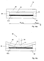
- FIG. 16a shows a section along the line A.
- the potentiometer 10 comprises a carrier 26, on which the segments 12.1 to 12.3 are applied, wherein in FIG. 16a only the segment 12.2 is shown.
- the cover membrane 32 is arranged, which hold a cover membrane 32 at a distance from the carrier 26.
- a flexible conductor 34 fixed in the form of a silver layer, which has an annular shape and is spaced from the segments 12.1 to 12.3.
- a pressure with a coupling device 36 on the cover membrane 32 causes the flexible conductor 34 deformed and so comes in contact with the respective segment, here with segment 12.2, in a contact point.
- an electrical contact between the flexible conductor 34 and the segment 12.2 is produced.
- the cover membrane 32, the flexible conductor 34 and the coupling device 36 are parts of a connecting device 38.
- the connecting device may also comprise known sliding contacts, which are rotatably mounted.
- FIG. 1a shows the coupling device 36 which is rotatably mounted in a center M by a rotation angle ⁇ .
- the coupling device 36 presses in two contact points P 1 , P 2 on the cover membrane 32 (FIG. FIG. 16b ) and thus closes the corresponding segments, in FIG. 1a the segments 12.1 and 12.2, in the contact points P 1 and P 2 short.
- the voltage which drops between two segments changes.
- the two contact points P 1 and P 2 are spaced from each other with respect to the center M by a spread angle ⁇ ( FIG. 1a ), which is larger than the angle range spanned by a segment, in the present case 120 °.
- FIG. 1b shows the corresponding to the rotation angle ⁇ equivalent circuit diagram for the potentiometer 10.
- the electrical resistance of each segment 12.1 to 12.3 is divided into two partial resistors, which represent the electrical resistance in the clockwise direction in front of the contact point P 1 , P 2 and thereafter.
- the sum of the partial resistors which are designated by the suffix "a” and "b” respectively, corresponds to the total resistance r of the segment.
- the size of each of the partial resistors depends on the angle of rotation ⁇ if one of the two contact points P 1 or P 2 is located in the relevant segment.
- FIG. 2a shows the potentiometer 10, in which the coupling device 36 is at a different angle of rotation ⁇ , so that the contact point P 1 is located in the segment 12.3 and the contact point P 2 is located in the segment 12.1.
- FIG. 2b shown equivalent circuit diagram.
- FIG. 3a shows a third possible position of the coupling device 36, in which the first contact point P 1 is located in the segment 12.2 and the second contact point P 2 is in the segment 12.3. This results in the FIG. 3b shown equivalent circuit diagram.
- FIG. 4a shows a second embodiment of a potentiometer 10 according to the invention with six segments 12.1, 12.2, 12.3, 12.4, 12.5 and 12.6.
- the segments 12.1 to 12.6 are arranged as described above for the first embodiment. Between the individual segments electrical contacts 22.1 to 22.6 are arranged.
- the contacts 22.1 and 22.4 are connected to a voltage source not shown, which is connected via the two electrical Contacts an electrical voltage V of example 5V applies, which has a current I result, which flows through all segments 12.1 to 12.6.
- FIGS. 5a, 5b . 6a, 6b . 7a, 7b . 8a, 8b . 9a, 9b . 10a, 10b . 11a, 11b . 12a, 12b . 13a, 13b . 14a, 14b and 15a or 15b respectively show the other possible positions of the coupling device 36 and the associated equivalent circuit diagrams.
- FIGS. 23a . 23b is derived below, which voltages between individual electrical contacts 22.1 to 22.6 for different rotation angle ⁇ can be measured.
- Figure 17a shows an alternative embodiment of a potentiometer 10 according to the invention, which has two segments 12.1 and 12.2, the edges have 16.1 and 16.2.
- the edges 16.1 and 16.2 border with their respective first sections 18.1 and 18.2 on the one hand and their second sections 20.1 and 20.2 on the other hand flush to each other so that they are in electrical contact with each other.
- the two segments 12.1, 12.2 form an annular arrangement, in the center of which M a connecting device 38 is mounted rotatably about the center M.
- the connecting device 38 has a first arm 40, a second arm 42 and a third arm 44, which at its end facing away from the midpoint M in a first contact point P 1 , in a second P 2 and in a third contact point P 3 in electrical Contact the respective segment. In this way sliding contacts are formed.
- an electrical current I is impressed by a current source not shown, coming from the current source via the first arm 40 through the contact point P 1 , through the segment 12.1 or through the segments 12.1 and 12.2, flows back through the contact point P 2 and the second arm 42 to the power source.
- the first arm 40 is electrically insulated from the second arm 42, so that a current flow from the first current contact to the second current contact through the two arms 40, 42 alone is not possible.
- an electrical voltage U can also be applied to the two current-carrying contacts 46, 48.
- an electrical voltage is formed between the contact points P 3 and P 1 and the contact points P 3 and P 2 , which voltage can be measured by a voltage measuring device, not shown. For this purpose, the voltage between the measuring contact 50 and the first current contact or the second current contact 48 is measured.
- FIG. 17b shows the equivalent circuit of the in Figure 17a shown potentiometer at the angular position ⁇ shown there.
- the notation of the resistors corresponds to the notation for the two embodiments described above.
- FIG. 18a shows the potentiometer in a different angular position and FIG. 18b shows the associated equivalent circuit diagram.
- the voltages measured between the first contact point P 1 and the third contact point P 3 or the second contact point P 2 and the third contact point P 3 can be calculated as follows for a given current I.
- a spread angle a between the two actuators of 90 ° is assumed.
- the resistance coating is assumed to be 10 ⁇ per degree (°).
- Each segment 12.1 to 12.6 sweeps 60 ° so that the resistance of a segment is 600 ⁇ .
- FIG. 4a a voltage is applied between the terminals 22.1 (+ 5V) and 22.4 (ground) and the angle ⁇ accordingly FIG. 12a changed between 240 and 270 °, so there is an equivalent circuit loud FIG. 12b .
- FIG. 4a a voltage is applied between the terminals 22.1 (+ 5V) and 22.4 (ground) and the angle ⁇ accordingly FIG. 13a changed between 270 and 300 °, so there is an equivalent circuit loud FIG. 13b ,
- a method according to the invention is carried out by passing a current I through the first and second energizing contacts 46 and 48, respectively.
- a voltage U or a current I is applied.
- a voltage U is first applied between the contact points P 1 and P 3 , then between the contact points P 2 and P 1 and then between P 3 and P 1 .
- the voltages U mess, U mess, 2 and U mess, 3 described above are measured.
- Each combination of these three voltages corresponds exactly to a rotation angle ⁇ which is interpolated from a table stored in a digital memory of a microprocessor-based electrical evaluation circuit.
- a prosthesis according to the invention preferably comprises two elements pivotable relative to one another about a pivoting angle. Is it the prosthesis? for example, a knee prosthesis, so are the two legs of the thigh (shaft) and the lower leg. The two legs of the prosthesis are interconnected so that pivoting of the two legs relative to one another uniquely effects rotation of the connecting device relative to the segments.
- pivoting of the two legs relative to one another results in movement of the connecting device of the potentiometer relative to the segments, and vice versa, rotational movement of the connecting device of the potentiometer relative to the segments of the potentiometer can only take place when the two legs are moved against each other.
- the angle can be determined under which, for example, the lower leg is oriented relative to the thigh. If the prosthesis according to the invention is, for example, a forearm prosthesis, the two thighs are the upper arm (stump) and the lower arm. If the prosthesis is a finger prosthesis, the corresponding applies.
- the potentiometer comprises an electrical controller arranged to determine the rotational position of the potentiometer.
- the electrical control is then preferably also surrounded by the enclosure. It is possible that the controller is configured to transmit the rotational position encoded wirelessly or wired outside the enclosure.
Landscapes
- Engineering & Computer Science (AREA)
- Microelectronics & Electronic Packaging (AREA)
- Physics & Mathematics (AREA)
- General Physics & Mathematics (AREA)
- Measurement Of Length, Angles, Or The Like Using Electric Or Magnetic Means (AREA)
- Transmission And Conversion Of Sensor Element Output (AREA)
- Agricultural Chemicals And Associated Chemicals (AREA)
Applications Claiming Priority (3)
| Application Number | Priority Date | Filing Date | Title |
|---|---|---|---|
| DE102007004536 | 2007-01-24 | ||
| DE102007014751A DE102007014751A1 (de) | 2007-01-24 | 2007-03-28 | Potentiometer |
| PCT/IB2008/001100 WO2008090478A2 (de) | 2007-01-24 | 2008-01-21 | Potentiometer und verfahren zum ermitteln einer winkellage eines bauteils |
Publications (2)
| Publication Number | Publication Date |
|---|---|
| EP2115752A2 EP2115752A2 (de) | 2009-11-11 |
| EP2115752B1 true EP2115752B1 (de) | 2013-02-27 |
Family
ID=39587416
Family Applications (1)
| Application Number | Title | Priority Date | Filing Date |
|---|---|---|---|
| EP08737583A Active EP2115752B1 (de) | 2007-01-24 | 2008-01-21 | Potentiometer, prothese umfassend dieses potentiometer und verfahren zum ermitteln einer winkellage eines bauteils mittels des potentiometers |
Country Status (11)
| Country | Link |
|---|---|
| US (1) | US8188835B2 (ko) |
| EP (1) | EP2115752B1 (ko) |
| JP (1) | JP5389667B2 (ko) |
| KR (1) | KR101509264B1 (ko) |
| CN (1) | CN101681704B (ko) |
| CA (1) | CA2676196C (ko) |
| DE (1) | DE102007014751A1 (ko) |
| ES (1) | ES2403035T3 (ko) |
| RU (1) | RU2469429C2 (ko) |
| TW (1) | TWI421884B (ko) |
| WO (1) | WO2008090478A2 (ko) |
Families Citing this family (33)
| Publication number | Priority date | Publication date | Assignee | Title |
|---|---|---|---|---|
| US9695616B2 (en) | 2013-03-15 | 2017-07-04 | August Home, Inc. | Intelligent door lock system and vibration/tapping sensing device to lock or unlock a door |
| US9725927B1 (en) | 2014-03-12 | 2017-08-08 | August Home, Inc. | System for intelligent door knob (handle) |
| US9916746B2 (en) | 2013-03-15 | 2018-03-13 | August Home, Inc. | Security system coupled to a door lock system |
| US11441332B2 (en) | 2013-03-15 | 2022-09-13 | August Home, Inc. | Mesh of cameras communicating with each other to follow a delivery agent within a dwelling |
| US9704314B2 (en) | 2014-08-13 | 2017-07-11 | August Home, Inc. | BLE/WiFi bridge that detects signal strength of Bluetooth LE devices at an exterior of a dwelling |
| US9382739B1 (en) | 2013-03-15 | 2016-07-05 | August Home, Inc. | Determining right or left hand side door installation |
| US9528294B2 (en) | 2013-03-15 | 2016-12-27 | August Home, Inc. | Intelligent door lock system with a torque limitor |
| US9322194B2 (en) | 2013-03-15 | 2016-04-26 | August Home, Inc. | Intelligent door lock system |
| US10140828B2 (en) | 2015-06-04 | 2018-11-27 | August Home, Inc. | Intelligent door lock system with camera and motion detector |
| US11352812B2 (en) | 2013-03-15 | 2022-06-07 | August Home, Inc. | Door lock system coupled to an image capture device |
| US11802422B2 (en) | 2013-03-15 | 2023-10-31 | August Home, Inc. | Video recording triggered by a smart lock device |
| US9706365B2 (en) | 2013-03-15 | 2017-07-11 | August Home, Inc. | BLE/WiFi bridge that detects signal strength of bluetooth LE devices at an interior of a dwelling |
| US9447609B2 (en) | 2013-03-15 | 2016-09-20 | August Home, Inc. | Mobile device that detects tappings/vibrations which are used to lock or unlock a door |
| US9359794B2 (en) | 2014-03-12 | 2016-06-07 | August Home, Inc. | Method for operating an intelligent door knob |
| US9574372B2 (en) | 2013-03-15 | 2017-02-21 | August Home, Inc. | Intelligent door lock system that minimizes inertia applied to components |
| US9818247B2 (en) | 2015-06-05 | 2017-11-14 | August Home, Inc. | Intelligent door lock system with keypad |
| US11043055B2 (en) | 2013-03-15 | 2021-06-22 | August Home, Inc. | Door lock system with contact sensor |
| US10388094B2 (en) | 2013-03-15 | 2019-08-20 | August Home Inc. | Intelligent door lock system with notification to user regarding battery status |
| US10443266B2 (en) | 2013-03-15 | 2019-10-15 | August Home, Inc. | Intelligent door lock system with manual operation and push notification |
| US11072945B2 (en) | 2013-03-15 | 2021-07-27 | August Home, Inc. | Video recording triggered by a smart lock device |
| US11527121B2 (en) | 2013-03-15 | 2022-12-13 | August Home, Inc. | Door lock system with contact sensor |
| US9326094B2 (en) | 2013-03-15 | 2016-04-26 | August Home, Inc. | BLE/WiFi bridge with audio sensor |
| US10181232B2 (en) | 2013-03-15 | 2019-01-15 | August Home, Inc. | Wireless access control system and methods for intelligent door lock system |
| US10691953B2 (en) | 2013-03-15 | 2020-06-23 | August Home, Inc. | Door lock system with one or more virtual fences |
| US11421445B2 (en) | 2013-03-15 | 2022-08-23 | August Home, Inc. | Smart lock device with near field communication |
| US9922481B2 (en) | 2014-03-12 | 2018-03-20 | August Home, Inc. | Intelligent door lock system with third party secured access to a dwelling |
| KR101490952B1 (ko) * | 2013-12-23 | 2015-02-09 | 현대자동차 주식회사 | 회전체의 위치를 파악하는 장치 및 이를 이용한 와이퍼 작동 장치 |
| JP6312077B2 (ja) * | 2014-01-08 | 2018-04-18 | アルプス電気株式会社 | 回転角検出装置 |
| CN105318833A (zh) * | 2015-12-05 | 2016-02-10 | 重庆镭宝激光智能机器人制造有限公司 | 一种焊接机器人旋转角度检测电流反馈装置 |
| US11269231B2 (en) | 2018-08-31 | 2022-03-08 | Gentex Corporation | Pulse-width modulation for clearing electro-optic device |
| US11959308B2 (en) | 2020-09-17 | 2024-04-16 | ASSA ABLOY Residential Group, Inc. | Magnetic sensor for lock position |
| CN114953700A (zh) * | 2021-12-06 | 2022-08-30 | 黄河水利职业技术学院 | 一种用于工业摄影测量的超高精度合作目标的制作方法 |
| CN116735930B (zh) * | 2023-08-15 | 2023-10-24 | 江苏华鹏智能仪表科技股份有限公司 | 一种集中器辅助工具 |
Family Cites Families (16)
| Publication number | Priority date | Publication date | Assignee | Title |
|---|---|---|---|---|
| SU584846A1 (ru) * | 1976-08-03 | 1977-12-25 | Предприятие П/Я В-8759 | Устройство дл регистрации положений отдельных сегментов тела человека в пространстве |
| JPS617003U (ja) * | 1984-06-19 | 1986-01-16 | 和泉電気株式会社 | メンブレンスイツチ構造の可変抵抗器 |
| DE3427000A1 (de) * | 1984-07-21 | 1986-01-30 | Philips Patentverwaltung | Ueberblend-schaltungseinrichtung an elektrischen wiedergabegeraeten und ueberblendregler fuer eine derartige schaltungseinrichtung |
| JPH05107016A (ja) * | 1991-05-17 | 1993-04-27 | Iwatsu Electric Co Ltd | 角度信号発生装置 |
| DE4339931C1 (de) * | 1993-11-24 | 1995-03-30 | Daimler Benz Ag | Positionsgeber, insbesondere für den Gangwählhebel eines Fahrzeuggetriebes |
| DE19649906C2 (de) * | 1996-12-02 | 1999-05-12 | Kostal Leopold Gmbh & Co Kg | Sensor zur Erfassung von Drehwinkeln |
| DE29812976U1 (de) * | 1997-07-23 | 1998-10-01 | Steinbock Boss GmbH Fördertechnik, 85368 Moosburg | Einrichtung zur potentiometrischen Messung der Relativstellung zweier relativ zueinander beweglicher Komponenten |
| DE19737063A1 (de) * | 1997-08-26 | 1999-03-04 | Bosch Gmbh Robert | Drehwinkelgeber |
| DE19816683A1 (de) * | 1998-04-15 | 1999-10-21 | Linde Ag | Vorrichtung zum Erfassen der Drehstellung eines Lenkrads |
| EP1228500B1 (en) | 1999-11-12 | 2003-06-11 | E.I. Du Pont De Nemours And Company | Drumsticks made from liquid crystalline polymer |
| ATE378027T1 (de) * | 2000-03-29 | 2007-11-15 | Massachusetts Inst Technology | Geschwindigkeitsangepasste und patientenangepasste knieprothese |
| KR100403855B1 (ko) * | 2001-09-15 | 2003-11-03 | 정헌술 | 불감대가 없는 무한 회전 전위차계 |
| KR100431251B1 (ko) | 2001-09-17 | 2004-05-12 | 정구명 | 건어멸치 선별장치 |
| JP2003254115A (ja) * | 2002-02-26 | 2003-09-10 | Yamaha Motor Co Ltd | スロットル開度センサ |
| DE102005005752A1 (de) * | 2005-02-07 | 2006-08-31 | Bourns, Inc., Riverside | Potentiometer |
| DE102005021890A1 (de) * | 2005-05-04 | 2006-11-09 | E.G.O. Elektro-Gerätebau GmbH | Bedienvorrichtung und Verfahren zur Auswertung einer Bedienvorrichtung |
-
2007
- 2007-03-28 DE DE102007014751A patent/DE102007014751A1/de not_active Withdrawn
-
2008
- 2008-01-21 ES ES08737583T patent/ES2403035T3/es active Active
- 2008-01-21 JP JP2009546840A patent/JP5389667B2/ja active Active
- 2008-01-21 RU RU2009131701/07A patent/RU2469429C2/ru active
- 2008-01-21 EP EP08737583A patent/EP2115752B1/de active Active
- 2008-01-21 WO PCT/IB2008/001100 patent/WO2008090478A2/de active Application Filing
- 2008-01-21 US US12/524,202 patent/US8188835B2/en active Active
- 2008-01-21 CN CN2008800086541A patent/CN101681704B/zh active Active
- 2008-01-21 CA CA2676196A patent/CA2676196C/en active Active
- 2008-01-21 KR KR20097017329A patent/KR101509264B1/ko active IP Right Grant
- 2008-01-23 TW TW097102468A patent/TWI421884B/zh active
Also Published As
| Publication number | Publication date |
|---|---|
| WO2008090478A2 (de) | 2008-07-31 |
| CN101681704A (zh) | 2010-03-24 |
| CN101681704B (zh) | 2012-07-25 |
| TWI421884B (zh) | 2014-01-01 |
| JP2010517033A (ja) | 2010-05-20 |
| CA2676196C (en) | 2015-02-17 |
| RU2009131701A (ru) | 2011-02-27 |
| RU2469429C2 (ru) | 2012-12-10 |
| KR101509264B1 (ko) | 2015-04-06 |
| ES2403035T3 (es) | 2013-05-13 |
| DE102007014751A1 (de) | 2008-08-07 |
| TW200845052A (en) | 2008-11-16 |
| US20090322465A1 (en) | 2009-12-31 |
| JP5389667B2 (ja) | 2014-01-15 |
| CA2676196A1 (en) | 2008-07-31 |
| KR20090104110A (ko) | 2009-10-05 |
| EP2115752A2 (de) | 2009-11-11 |
| WO2008090478A3 (de) | 2009-02-19 |
| US8188835B2 (en) | 2012-05-29 |
Similar Documents
| Publication | Publication Date | Title |
|---|---|---|
| EP2115752B1 (de) | Potentiometer, prothese umfassend dieses potentiometer und verfahren zum ermitteln einer winkellage eines bauteils mittels des potentiometers | |
| EP2820382B1 (de) | Vorrichtung und verfahren zur redundanten, absoluten positionsbestimmung eines beweglichen körpers | |
| DE3013129C2 (de) | Detektorvorrichtung für die X- und Y-Koordinaten von Eingabepunkten | |
| DE2813068A1 (de) | Verfahren und vorrichtung zur ermittlung von inneren koerperstrukturen | |
| WO1999053286A1 (de) | Kapazitive druck- oder kraftsensorstruktur und verfahren zur herstellung derselben | |
| DE69209017T2 (de) | Winkelposition-Sensor mit fortlaufender geschlossener Widerstandsspur und Messverfahren dafür | |
| DE2326043A1 (de) | Abgreifbare festimpedanzen | |
| DE2649251A1 (de) | Kommandogeber fuer elektrische positionierantriebe | |
| DE3884459T2 (de) | Ununterbrochener biegsamer elektrischer Leiter, funktionsfähig wie ein elektrischer Schalter. | |
| DE2650018C2 (de) | Elektrische Abschwächereinrichtung für Tonwiedergabesysteme | |
| DE19701137B4 (de) | Längensensorchip, dessen Ebene einer Maßstabsebene gegenübersteht | |
| DE1813153A1 (de) | Vorrichtung zur Umformung einer mechanischen Wegaenderung in elektrische Signale | |
| DE19824778C2 (de) | Druck- oder Kraftsensorstruktur und Verfahren zur Herstellung derselben | |
| DE10159258B4 (de) | Anordnung zur Auswertung der Stellung eines Drehpotentiometers | |
| EP3738211B1 (de) | Verfahren zur bestimmung der auslenkung des betätigungsglieds eines kapazitiven mehrwege-kraftsensorbausteins | |
| DE102018123853A1 (de) | Eingabevorrichtung mit beweglicher Handhabe auf kapazitiver Detektionsfläche und räumlich alternierender kapazitiver Kopplung | |
| DE102018105857A1 (de) | Vorrichtung zum Messen von Strom und Verfahren zur Herstellung | |
| DE2534126A1 (de) | Leiterplatte mit einer gedruckten schaltung | |
| DE102019114185B4 (de) | Taktiles Sensorelement | |
| DE2613739A1 (de) | Elektrischer messwertgeber fuer einen winkelmesser | |
| DE2135194C3 (de) | Passiver elektrischer Vierpol mit einstellbarem Eingangswiderstand | |
| DE2310162C3 (de) | Elektrisch auslesbares dezimales Ziffernrollenzählwerk | |
| DE102021206756A1 (de) | Strommesseinrichtung zur berührungslosen Strommessung, Verwendung, Magnetfeldsensoreinheit zur berührungslosen Messung sowie Verfahren zur berührungslosen Strommessung | |
| DE102012020148A1 (de) | Verstärker zum Verstärken kleiner elektrischer Ströme | |
| DE3005235C2 (de) | Anordnung von Kontakten mit kreisförmigem Querschnitt für Buchse und Stecker |
Legal Events
| Date | Code | Title | Description |
|---|---|---|---|
| PUAI | Public reference made under article 153(3) epc to a published international application that has entered the european phase |
Free format text: ORIGINAL CODE: 0009012 |
|
| 17P | Request for examination filed |
Effective date: 20090820 |
|
| AK | Designated contracting states |
Kind code of ref document: A2 Designated state(s): AT BE BG CH CY CZ DE DK EE ES FI FR GB GR HR HU IE IS IT LI LT LU LV MC MT NL NO PL PT RO SE SI SK TR |
|
| RIN1 | Information on inventor provided before grant (corrected) |
Inventor name: EDER, MARCUS Inventor name: INSCHLAG, JOSEF |
|
| DAX | Request for extension of the european patent (deleted) | ||
| GRAP | Despatch of communication of intention to grant a patent |
Free format text: ORIGINAL CODE: EPIDOSNIGR1 |
|
| RIC1 | Information provided on ipc code assigned before grant |
Ipc: H01C 10/32 20060101ALI20120823BHEP Ipc: H01B 7/30 20060101ALI20120823BHEP Ipc: H01C 10/30 20060101AFI20120823BHEP |
|
| GRAS | Grant fee paid |
Free format text: ORIGINAL CODE: EPIDOSNIGR3 |
|
| GRAA | (expected) grant |
Free format text: ORIGINAL CODE: 0009210 |
|
| AK | Designated contracting states |
Kind code of ref document: B1 Designated state(s): AT BE BG CH CY CZ DE DK EE ES FI FR GB GR HR HU IE IS IT LI LT LU LV MC MT NL NO PL PT RO SE SI SK TR |
|
| REG | Reference to a national code |
Ref country code: GB Ref legal event code: FG4D Free format text: NOT ENGLISH |
|
| REG | Reference to a national code |
Ref country code: CH Ref legal event code: EP |
|
| REG | Reference to a national code |
Ref country code: AT Ref legal event code: REF Ref document number: 598871 Country of ref document: AT Kind code of ref document: T Effective date: 20130315 |
|
| REG | Reference to a national code |
Ref country code: IE Ref legal event code: FG4D Free format text: LANGUAGE OF EP DOCUMENT: GERMAN |
|
| REG | Reference to a national code |
Ref country code: CH Ref legal event code: NV Representative=s name: BRAUNPAT BRAUN EDER AG, CH |
|
| REG | Reference to a national code |
Ref country code: SE Ref legal event code: TRGR |
|
| REG | Reference to a national code |
Ref country code: DE Ref legal event code: R096 Ref document number: 502008009341 Country of ref document: DE Effective date: 20130425 |
|
| REG | Reference to a national code |
Ref country code: ES Ref legal event code: FG2A Ref document number: 2403035 Country of ref document: ES Kind code of ref document: T3 Effective date: 20130513 |
|
| REG | Reference to a national code |
Ref country code: NL Ref legal event code: T3 |
|
| REG | Reference to a national code |
Ref country code: LT Ref legal event code: MG4D |
|
| PG25 | Lapsed in a contracting state [announced via postgrant information from national office to epo] |
Ref country code: LT Free format text: LAPSE BECAUSE OF FAILURE TO SUBMIT A TRANSLATION OF THE DESCRIPTION OR TO PAY THE FEE WITHIN THE PRESCRIBED TIME-LIMIT Effective date: 20130227 Ref country code: NO Free format text: LAPSE BECAUSE OF FAILURE TO SUBMIT A TRANSLATION OF THE DESCRIPTION OR TO PAY THE FEE WITHIN THE PRESCRIBED TIME-LIMIT Effective date: 20130527 Ref country code: BG Free format text: LAPSE BECAUSE OF FAILURE TO SUBMIT A TRANSLATION OF THE DESCRIPTION OR TO PAY THE FEE WITHIN THE PRESCRIBED TIME-LIMIT Effective date: 20130527 Ref country code: IS Free format text: LAPSE BECAUSE OF FAILURE TO SUBMIT A TRANSLATION OF THE DESCRIPTION OR TO PAY THE FEE WITHIN THE PRESCRIBED TIME-LIMIT Effective date: 20130627 |
|
| PG25 | Lapsed in a contracting state [announced via postgrant information from national office to epo] |
Ref country code: SI Free format text: LAPSE BECAUSE OF FAILURE TO SUBMIT A TRANSLATION OF THE DESCRIPTION OR TO PAY THE FEE WITHIN THE PRESCRIBED TIME-LIMIT Effective date: 20130227 Ref country code: GR Free format text: LAPSE BECAUSE OF FAILURE TO SUBMIT A TRANSLATION OF THE DESCRIPTION OR TO PAY THE FEE WITHIN THE PRESCRIBED TIME-LIMIT Effective date: 20130528 Ref country code: PT Free format text: LAPSE BECAUSE OF FAILURE TO SUBMIT A TRANSLATION OF THE DESCRIPTION OR TO PAY THE FEE WITHIN THE PRESCRIBED TIME-LIMIT Effective date: 20130627 Ref country code: FI Free format text: LAPSE BECAUSE OF FAILURE TO SUBMIT A TRANSLATION OF THE DESCRIPTION OR TO PAY THE FEE WITHIN THE PRESCRIBED TIME-LIMIT Effective date: 20130227 Ref country code: LV Free format text: LAPSE BECAUSE OF FAILURE TO SUBMIT A TRANSLATION OF THE DESCRIPTION OR TO PAY THE FEE WITHIN THE PRESCRIBED TIME-LIMIT Effective date: 20130227 Ref country code: PL Free format text: LAPSE BECAUSE OF FAILURE TO SUBMIT A TRANSLATION OF THE DESCRIPTION OR TO PAY THE FEE WITHIN THE PRESCRIBED TIME-LIMIT Effective date: 20130227 |
|
| PG25 | Lapsed in a contracting state [announced via postgrant information from national office to epo] |
Ref country code: HR Free format text: LAPSE BECAUSE OF FAILURE TO SUBMIT A TRANSLATION OF THE DESCRIPTION OR TO PAY THE FEE WITHIN THE PRESCRIBED TIME-LIMIT Effective date: 20130227 |
|
| PG25 | Lapsed in a contracting state [announced via postgrant information from national office to epo] |
Ref country code: EE Free format text: LAPSE BECAUSE OF FAILURE TO SUBMIT A TRANSLATION OF THE DESCRIPTION OR TO PAY THE FEE WITHIN THE PRESCRIBED TIME-LIMIT Effective date: 20130227 Ref country code: RO Free format text: LAPSE BECAUSE OF FAILURE TO SUBMIT A TRANSLATION OF THE DESCRIPTION OR TO PAY THE FEE WITHIN THE PRESCRIBED TIME-LIMIT Effective date: 20130227 Ref country code: DK Free format text: LAPSE BECAUSE OF FAILURE TO SUBMIT A TRANSLATION OF THE DESCRIPTION OR TO PAY THE FEE WITHIN THE PRESCRIBED TIME-LIMIT Effective date: 20130227 Ref country code: CZ Free format text: LAPSE BECAUSE OF FAILURE TO SUBMIT A TRANSLATION OF THE DESCRIPTION OR TO PAY THE FEE WITHIN THE PRESCRIBED TIME-LIMIT Effective date: 20130227 Ref country code: SK Free format text: LAPSE BECAUSE OF FAILURE TO SUBMIT A TRANSLATION OF THE DESCRIPTION OR TO PAY THE FEE WITHIN THE PRESCRIBED TIME-LIMIT Effective date: 20130227 |
|
| PG25 | Lapsed in a contracting state [announced via postgrant information from national office to epo] |
Ref country code: CY Free format text: LAPSE BECAUSE OF FAILURE TO SUBMIT A TRANSLATION OF THE DESCRIPTION OR TO PAY THE FEE WITHIN THE PRESCRIBED TIME-LIMIT Effective date: 20130227 |
|
| PLBE | No opposition filed within time limit |
Free format text: ORIGINAL CODE: 0009261 |
|
| STAA | Information on the status of an ep patent application or granted ep patent |
Free format text: STATUS: NO OPPOSITION FILED WITHIN TIME LIMIT |
|
| 26N | No opposition filed |
Effective date: 20131128 |
|
| REG | Reference to a national code |
Ref country code: DE Ref legal event code: R097 Ref document number: 502008009341 Country of ref document: DE Effective date: 20131128 |
|
| BERE | Be: lapsed |
Owner name: OTTO BOCK HEALTHCARE PRODUCTS GMBH Effective date: 20140131 |
|
| PG25 | Lapsed in a contracting state [announced via postgrant information from national office to epo] |
Ref country code: LU Free format text: LAPSE BECAUSE OF FAILURE TO SUBMIT A TRANSLATION OF THE DESCRIPTION OR TO PAY THE FEE WITHIN THE PRESCRIBED TIME-LIMIT Effective date: 20140121 Ref country code: MC Free format text: LAPSE BECAUSE OF FAILURE TO SUBMIT A TRANSLATION OF THE DESCRIPTION OR TO PAY THE FEE WITHIN THE PRESCRIBED TIME-LIMIT Effective date: 20130227 |
|
| REG | Reference to a national code |
Ref country code: IE Ref legal event code: MM4A |
|
| PG25 | Lapsed in a contracting state [announced via postgrant information from national office to epo] |
Ref country code: IE Free format text: LAPSE BECAUSE OF NON-PAYMENT OF DUE FEES Effective date: 20140121 Ref country code: BE Free format text: LAPSE BECAUSE OF NON-PAYMENT OF DUE FEES Effective date: 20140131 |
|
| REG | Reference to a national code |
Ref country code: DE Ref legal event code: R082 Ref document number: 502008009341 Country of ref document: DE Representative=s name: GRAMM, LINS & PARTNER PATENT- UND RECHTSANWAEL, DE |
|
| REG | Reference to a national code |
Ref country code: FR Ref legal event code: PLFP Year of fee payment: 9 |
|
| PG25 | Lapsed in a contracting state [announced via postgrant information from national office to epo] |
Ref country code: MT Free format text: LAPSE BECAUSE OF FAILURE TO SUBMIT A TRANSLATION OF THE DESCRIPTION OR TO PAY THE FEE WITHIN THE PRESCRIBED TIME-LIMIT Effective date: 20130227 |
|
| PG25 | Lapsed in a contracting state [announced via postgrant information from national office to epo] |
Ref country code: HU Free format text: LAPSE BECAUSE OF FAILURE TO SUBMIT A TRANSLATION OF THE DESCRIPTION OR TO PAY THE FEE WITHIN THE PRESCRIBED TIME-LIMIT; INVALID AB INITIO Effective date: 20080121 |
|
| REG | Reference to a national code |
Ref country code: FR Ref legal event code: PLFP Year of fee payment: 10 |
|
| REG | Reference to a national code |
Ref country code: FR Ref legal event code: PLFP Year of fee payment: 11 |
|
| REG | Reference to a national code |
Ref country code: CH Ref legal event code: PCAR Free format text: NEW ADDRESS: HOLEESTRASSE 87, 4054 BASEL (CH) |
|
| PGFP | Annual fee paid to national office [announced via postgrant information from national office to epo] |
Ref country code: ES Payment date: 20190215 Year of fee payment: 12 Ref country code: NL Payment date: 20190122 Year of fee payment: 12 Ref country code: CH Payment date: 20190124 Year of fee payment: 12 |
|
| PGFP | Annual fee paid to national office [announced via postgrant information from national office to epo] |
Ref country code: TR Payment date: 20190111 Year of fee payment: 12 Ref country code: SE Payment date: 20190124 Year of fee payment: 12 Ref country code: AT Payment date: 20190118 Year of fee payment: 12 |
|
| REG | Reference to a national code |
Ref country code: CH Ref legal event code: PL |
|
| REG | Reference to a national code |
Ref country code: SE Ref legal event code: EUG |
|
| REG | Reference to a national code |
Ref country code: NL Ref legal event code: MM Effective date: 20200201 |
|
| REG | Reference to a national code |
Ref country code: AT Ref legal event code: MM01 Ref document number: 598871 Country of ref document: AT Kind code of ref document: T Effective date: 20200121 |
|
| REG | Reference to a national code |
Ref country code: SE Ref legal event code: EUG |
|
| PG25 | Lapsed in a contracting state [announced via postgrant information from national office to epo] |
Ref country code: NL Free format text: LAPSE BECAUSE OF NON-PAYMENT OF DUE FEES Effective date: 20200201 Ref country code: SE Free format text: LAPSE BECAUSE OF NON-PAYMENT OF DUE FEES Effective date: 20200122 |
|
| PG25 | Lapsed in a contracting state [announced via postgrant information from national office to epo] |
Ref country code: CH Free format text: LAPSE BECAUSE OF NON-PAYMENT OF DUE FEES Effective date: 20200131 Ref country code: AT Free format text: LAPSE BECAUSE OF NON-PAYMENT OF DUE FEES Effective date: 20200121 Ref country code: LI Free format text: LAPSE BECAUSE OF NON-PAYMENT OF DUE FEES Effective date: 20200131 |
|
| REG | Reference to a national code |
Ref country code: ES Ref legal event code: FD2A Effective date: 20210604 |
|
| PG25 | Lapsed in a contracting state [announced via postgrant information from national office to epo] |
Ref country code: ES Free format text: LAPSE BECAUSE OF NON-PAYMENT OF DUE FEES Effective date: 20200122 |
|
| PG25 | Lapsed in a contracting state [announced via postgrant information from national office to epo] |
Ref country code: TR Free format text: LAPSE BECAUSE OF NON-PAYMENT OF DUE FEES Effective date: 20200121 |
|
| PGFP | Annual fee paid to national office [announced via postgrant information from national office to epo] |
Ref country code: DE Payment date: 20240119 Year of fee payment: 17 Ref country code: GB Payment date: 20240124 Year of fee payment: 17 |
|
| PGFP | Annual fee paid to national office [announced via postgrant information from national office to epo] |
Ref country code: IT Payment date: 20240131 Year of fee payment: 17 Ref country code: FR Payment date: 20240124 Year of fee payment: 17 |