EP2115666B1 - Electronic payment, information, or id card with a deformation sensing means - Google Patents
Electronic payment, information, or id card with a deformation sensing means Download PDFInfo
- Publication number
- EP2115666B1 EP2115666B1 EP08717184A EP08717184A EP2115666B1 EP 2115666 B1 EP2115666 B1 EP 2115666B1 EP 08717184 A EP08717184 A EP 08717184A EP 08717184 A EP08717184 A EP 08717184A EP 2115666 B1 EP2115666 B1 EP 2115666B1
- Authority
- EP
- European Patent Office
- Prior art keywords
- card
- sensing means
- information
- processor
- mode
- Prior art date
- Legal status (The legal status is an assumption and is not a legal conclusion. Google has not performed a legal analysis and makes no representation as to the accuracy of the status listed.)
- Active
Links
Images

Classifications
-
- G—PHYSICS
- G06—COMPUTING OR CALCULATING; COUNTING
- G06K—GRAPHICAL DATA READING; PRESENTATION OF DATA; RECORD CARRIERS; HANDLING RECORD CARRIERS
- G06K19/00—Record carriers for use with machines and with at least a part designed to carry digital markings
- G06K19/06—Record carriers for use with machines and with at least a part designed to carry digital markings characterised by the kind of the digital marking, e.g. shape, nature, code
- G06K19/067—Record carriers with conductive marks, printed circuits or semiconductor circuit elements, e.g. credit or identity cards also with resonating or responding marks without active components
- G06K19/07—Record carriers with conductive marks, printed circuits or semiconductor circuit elements, e.g. credit or identity cards also with resonating or responding marks without active components with integrated circuit chips
- G06K19/077—Constructional details, e.g. mounting of circuits in the carrier
-
- G—PHYSICS
- G06—COMPUTING OR CALCULATING; COUNTING
- G06K—GRAPHICAL DATA READING; PRESENTATION OF DATA; RECORD CARRIERS; HANDLING RECORD CARRIERS
- G06K19/00—Record carriers for use with machines and with at least a part designed to carry digital markings
- G06K19/06—Record carriers for use with machines and with at least a part designed to carry digital markings characterised by the kind of the digital marking, e.g. shape, nature, code
- G06K19/067—Record carriers with conductive marks, printed circuits or semiconductor circuit elements, e.g. credit or identity cards also with resonating or responding marks without active components
- G06K19/07—Record carriers with conductive marks, printed circuits or semiconductor circuit elements, e.g. credit or identity cards also with resonating or responding marks without active components with integrated circuit chips
- G06K19/0701—Record carriers with conductive marks, printed circuits or semiconductor circuit elements, e.g. credit or identity cards also with resonating or responding marks without active components with integrated circuit chips at least one of the integrated circuit chips comprising an arrangement for power management
- G06K19/0702—Record carriers with conductive marks, printed circuits or semiconductor circuit elements, e.g. credit or identity cards also with resonating or responding marks without active components with integrated circuit chips at least one of the integrated circuit chips comprising an arrangement for power management the arrangement including a battery
- G06K19/0705—Record carriers with conductive marks, printed circuits or semiconductor circuit elements, e.g. credit or identity cards also with resonating or responding marks without active components with integrated circuit chips at least one of the integrated circuit chips comprising an arrangement for power management the arrangement including a battery the battery being connected to a power saving arrangement
-
- G—PHYSICS
- G06—COMPUTING OR CALCULATING; COUNTING
- G06K—GRAPHICAL DATA READING; PRESENTATION OF DATA; RECORD CARRIERS; HANDLING RECORD CARRIERS
- G06K19/00—Record carriers for use with machines and with at least a part designed to carry digital markings
- G06K19/06—Record carriers for use with machines and with at least a part designed to carry digital markings characterised by the kind of the digital marking, e.g. shape, nature, code
- G06K19/067—Record carriers with conductive marks, printed circuits or semiconductor circuit elements, e.g. credit or identity cards also with resonating or responding marks without active components
- G06K19/07—Record carriers with conductive marks, printed circuits or semiconductor circuit elements, e.g. credit or identity cards also with resonating or responding marks without active components with integrated circuit chips
- G06K19/0716—Record carriers with conductive marks, printed circuits or semiconductor circuit elements, e.g. credit or identity cards also with resonating or responding marks without active components with integrated circuit chips at least one of the integrated circuit chips comprising a sensor or an interface to a sensor
-
- G—PHYSICS
- G06—COMPUTING OR CALCULATING; COUNTING
- G06K—GRAPHICAL DATA READING; PRESENTATION OF DATA; RECORD CARRIERS; HANDLING RECORD CARRIERS
- G06K19/00—Record carriers for use with machines and with at least a part designed to carry digital markings
- G06K19/06—Record carriers for use with machines and with at least a part designed to carry digital markings characterised by the kind of the digital marking, e.g. shape, nature, code
- G06K19/067—Record carriers with conductive marks, printed circuits or semiconductor circuit elements, e.g. credit or identity cards also with resonating or responding marks without active components
- G06K19/07—Record carriers with conductive marks, printed circuits or semiconductor circuit elements, e.g. credit or identity cards also with resonating or responding marks without active components with integrated circuit chips
- G06K19/077—Constructional details, e.g. mounting of circuits in the carrier
- G06K19/07701—Constructional details, e.g. mounting of circuits in the carrier the record carrier comprising an interface suitable for human interaction
- G06K19/07703—Constructional details, e.g. mounting of circuits in the carrier the record carrier comprising an interface suitable for human interaction the interface being visual
-
- G—PHYSICS
- G06—COMPUTING OR CALCULATING; COUNTING
- G06Q—INFORMATION AND COMMUNICATION TECHNOLOGY [ICT] SPECIALLY ADAPTED FOR ADMINISTRATIVE, COMMERCIAL, FINANCIAL, MANAGERIAL OR SUPERVISORY PURPOSES; SYSTEMS OR METHODS SPECIALLY ADAPTED FOR ADMINISTRATIVE, COMMERCIAL, FINANCIAL, MANAGERIAL OR SUPERVISORY PURPOSES, NOT OTHERWISE PROVIDED FOR
- G06Q20/00—Payment architectures, schemes or protocols
- G06Q20/30—Payment architectures, schemes or protocols characterised by the use of specific devices or networks
- G06Q20/34—Payment architectures, schemes or protocols characterised by the use of specific devices or networks using cards, e.g. integrated circuit [IC] cards or magnetic cards
- G06Q20/341—Active cards, i.e. cards including their own processing means, e.g. including an IC or chip
-
- G—PHYSICS
- G06—COMPUTING OR CALCULATING; COUNTING
- G06Q—INFORMATION AND COMMUNICATION TECHNOLOGY [ICT] SPECIALLY ADAPTED FOR ADMINISTRATIVE, COMMERCIAL, FINANCIAL, MANAGERIAL OR SUPERVISORY PURPOSES; SYSTEMS OR METHODS SPECIALLY ADAPTED FOR ADMINISTRATIVE, COMMERCIAL, FINANCIAL, MANAGERIAL OR SUPERVISORY PURPOSES, NOT OTHERWISE PROVIDED FOR
- G06Q20/00—Payment architectures, schemes or protocols
- G06Q20/30—Payment architectures, schemes or protocols characterised by the use of specific devices or networks
- G06Q20/34—Payment architectures, schemes or protocols characterised by the use of specific devices or networks using cards, e.g. integrated circuit [IC] cards or magnetic cards
- G06Q20/352—Contactless payments by cards
-
- G—PHYSICS
- G06—COMPUTING OR CALCULATING; COUNTING
- G06Q—INFORMATION AND COMMUNICATION TECHNOLOGY [ICT] SPECIALLY ADAPTED FOR ADMINISTRATIVE, COMMERCIAL, FINANCIAL, MANAGERIAL OR SUPERVISORY PURPOSES; SYSTEMS OR METHODS SPECIALLY ADAPTED FOR ADMINISTRATIVE, COMMERCIAL, FINANCIAL, MANAGERIAL OR SUPERVISORY PURPOSES, NOT OTHERWISE PROVIDED FOR
- G06Q20/00—Payment architectures, schemes or protocols
- G06Q20/30—Payment architectures, schemes or protocols characterised by the use of specific devices or networks
- G06Q20/34—Payment architectures, schemes or protocols characterised by the use of specific devices or networks using cards, e.g. integrated circuit [IC] cards or magnetic cards
- G06Q20/354—Card activation or deactivation
-
- G—PHYSICS
- G07—CHECKING-DEVICES
- G07F—COIN-FREED OR LIKE APPARATUS
- G07F7/00—Mechanisms actuated by objects other than coins to free or to actuate vending, hiring, coin or paper currency dispensing or refunding apparatus
- G07F7/08—Mechanisms actuated by objects other than coins to free or to actuate vending, hiring, coin or paper currency dispensing or refunding apparatus by coded identity card or credit card or other personal identification means
- G07F7/0806—Details of the card
- G07F7/0813—Specific details related to card security
-
- G—PHYSICS
- G07—CHECKING-DEVICES
- G07F—COIN-FREED OR LIKE APPARATUS
- G07F7/00—Mechanisms actuated by objects other than coins to free or to actuate vending, hiring, coin or paper currency dispensing or refunding apparatus
- G07F7/08—Mechanisms actuated by objects other than coins to free or to actuate vending, hiring, coin or paper currency dispensing or refunding apparatus by coded identity card or credit card or other personal identification means
- G07F7/0866—Mechanisms actuated by objects other than coins to free or to actuate vending, hiring, coin or paper currency dispensing or refunding apparatus by coded identity card or credit card or other personal identification means by active credit-cards adapted therefor
Definitions
- the present invention relates to portable cards, such as ID cards, Information cards, or payment cards, having an electric circuit which transitions from one mode to the other when instructed to do so by a user.
- This type of technology may be used for a variety of purposes.
- One purpose is seen as a switch in e.g. a payment card or identification card in which a processor or other electronic circuit Is operated or receives instructions from the user via a switch.
- a switch In order to increase the life time of the card, it is desired that the processor and switch use power only when required.
- Such cards comprise mechanical domes or membrane switches which are to be depressed by the user in order to e.g. activate the processor.
- Such switches have a number of disadvantages. Domes extend from the generally flat surface of the card and the production/lamination process of the card may render the dome switch useless. Both switch solutions require a current flow during operation, and a switch, which is permanently deformed in the depressed state, may swiftly deplete the power source of the card.
- the invention relates to a portable card according to claim 1.
- deforming the sensing means will mean bringing the sensing means away from a rest position by, normally, providing a force thereto.
- This force is normally provided at an angle to a direction along which the sensing means has an extent larger than perpendicularly thereto.
- bending of an elongate object normally is achieved by providing a force at an angle to the longitudinal axis thereof
- bending of a disc-shaped element normally is achieved by providing a force at an angle to a plane of the disc- or plate-shaped element.
- the sensing means need not be plane in the rest position, whereas it may be plane in the bent or stressed/deformed position.
- the present sensor type is a piezo electric element in that this additionally has the ability to provide power when deformed or bent. Thus, this type of sensor does not require power in order to be operative and need therefore not be connected to any power source.
- the sleep mode is a mode with a lower power consumption and the operating mode is a mode with a higher power consumption.
- the sensing means when deformed, is adapted to provide a signal or power to the processor so as to bring the processor from the sleep mode to the operating mode.
- power saving may be achieved by the processor using no or very little power before the sensor is bent/deformed.
- the card is rather small, such as having outer dimensions of: a length of less than 10 cm, a width of less than 5 cm, and a thickness of less than 2 mm.
- the mostly preferred card has the size of a standard credit card or ID card.
- the card comprises a flexible base element to which the sensing means is fixed in order for the card to be bendable or deformable in order to infer the bending/deformation to the sensing means.
- the sensing means may be fully embedded in the card, such as during lamination of the card, and still be operable from the outside of the card.
- the card may comprise any number of layers, such as layers laminated to the base element. This is known in the art of providing e.g. chip cards.
- the sensing means in a cross section perpendicular to a plane of the card, is provided adjacent to a layer or element being softer at a centre of the sensing means than (a material or element positioned) at outer parts thereof.
- the sensing means may be forced toward the softer layer so as to deform the softer layer while deforming the sensing means.
- a switch type element may be provided which may still be fully positioned within the, normally, two generally flat major outer surfaces of a card.
- a dome on top of the sensing means could also be used to provide a hammer effect when the dome is depressed.
- the transition When the transition is performed when bending/deforming the sensing means, it may, in certain situations, be noticed if the sensing means or the card is often bent/deformed without further actions taken, whereby the resulting transition might not be meant to be taking place.
- the bending/deformation may be performed accidentally.
- One situation may be when a rhythmic bending is detected, such as when the sensor is bent/deformed by a person walking/running/dancing.
- the card may further comprise means for reducing a sensitivity to deformation of the sensing means or reducing the circuit's sensitivity to the signal from the sensing means.
- the card further comprises an operating means adapted to be operated and initiate a task, the reducing means being operated, if a predetermined number of deformations of the sensing means have been detected while no operation of the operating means has been performed.
- the operating means may be the sensing means operated once more or a means sensing another input, such as the entering a code on a keyboard of the card, reading a fingerprint by a fingerprint reader of the card, the card sensing proximity of a card reader, an optical sensor of the card sensing an optical signal or the like.
- the mode change may be performed or maintained until a new deformation of the sensing means is performed or for a period of time after the initial deformation.
- This period of time may simply be determined by a timing device, an RC circuit being provided with a voltage at the time of (or actually by the) deformation of the sensing device and subsequently decaying. The point of time of mode change then being either at the time of deformation or when the voltage of the decaying RC circuit reaching a threshold.
- the circuit may be circuitry of an RFID tag, where the transmitting/receiving circuit thereof is enabled or disabled when the sensing means is deformed, or a predetermined period of time thereafter.
- the operation of the RFID tag may be powered by power provided by the sensing means when deformed. In this situation, no battery may be required to have the RFID tag operate.
- the deformation of the sensing means may be determined and used for multiple purposes.
- the first operation or “click” thereof may be used for the transition.
- a “double click” may be used for starting a predetermined task, and any number of deformations, such as performed within a certain period of time or with no longer than a predetermined period of time between individual deformations (much as the use of a computer mouse or a cell phone) may be used as inputs and for controlling the operation of the card circuit.
- a quantification of the deformation may alternatively be used for selecting a mode.
- the card further comprises a power source to which the processor is coupled, but the sensing means adapted to provide the power/signal from the operation of the sensing means is not connected to the power source. In that manner, malfunctioning of the sensing means need not deplete the power source.
- intelligent cards also comprise means for outputting information from the card.
- Such means may be one or more magnetic stripes, active or passive (changeable or not by the circuit/processor), via electrically conducting pads on the card, or via wireless means, such as radio waves, magnetic fields, RFID, IR radiation, or Bluetooth.
- this communication may be controlled by the processor and may be initiated only when e.g. the processor has been awakened by operation of the sensor.
- the card further comprises means for presenting visual information.
- This visible information may inform the user of a status of or a process performed by the circuit. It may be used for outputting information to the user for use in other processes, such as codes to be entered into an ATM, a computer, a console or the like.
- the card comprises means for providing, on the basis of the signal from the sensing means, second information or signals to the presenting means.
- information may be derived and used as to the degree or amount of deformation, direction of deformation, frequency of the deformation, or other information derivable from the deformation.
- the sensing means may be adapted to output a signal with a voltage and/or current related to the degree and/or direction of deformation, or a time duration of the signal may be used for estimating the degree of deformation.
- the invention relates to a method according to claim 7.
- the card may comprise a flexible base layer to which the sensing means is fixed, wherein the deforming step comprises bending the card or base layer.
- the sensing means may, In a cross section perpendicular to a plane of the card, be provided adjacent to a layer or an element being softer at a center of the sensing means than (e.g. another material or element positioned) at outer parts thereof, the deforming step comprises forcing at least a central portion of the sensing means toward the softer layer and thereby deforming the softer layer.
- the sensing means may be provided within the desired, even surfaces of the card while being operable as a switch.
- the deformation of the sensing means is obtained by depressing the sensing means (or the part above the softer material) toward the softer material so as to deform this material also.
- the softer material or element may be replaced simply by a hole or cavity in the base layer so as to provide space for the sensing means to deform into.
- the method further comprises the step of reducing a sensitivity of the sensing means or the circuit.
- the reducing step is preceded by the step of sensing a predetermined number of deformations/bendings of the sensing means while receiving no instruction to perform additional tasks.
- Such instructions may be received via other types of sensors, such as sweep sensors, contact pads, other switches or the same switch. This is described above.
- the method further comprises the step of presenting visual information to a user from the card. This presenting may be via a display of the card.
- an embodiment may be provided which further comprises the step of the circuit providing, on the basis of the signal from the sensing means, second information to the presenting means.
- the displacement of a part of the card during bending/deformation is used for providing the information.
- the card 10 has a processor 12 connected to a sensor 14, a power supply 16, an output means 18, and a display 20.
- the power supply 16 which may be a battery or the like, and which may be rechargeable or not, also feeds the output means 18 and the display 20.
- the card is of the size of a standard credit card and fulfils the requirements of ISO standard No. 7810 relating to the physical characteristics of identification cards.
- the output means 18 may be any type of output means, such as an "old fashioned" magnetic strip, a dynamic magnetic strip, which may be controlled by the processor 12 both as to whether to provide a magnetic field and as to which information to provide via the magnetic field.
- the outputting means may be one or more electrically conducting pads connected to the processor 12 via which communication with a reader may take place.
- a further manner of communicating between card and a reader is via wireless standards, such as Bluetooth, RFID, magnetic fields, radio waves, or via electromagnetic radiation. Suitable output means may be seen in WO2005/086102 by the present Applicant.
- the processor may comprise one or more memories, such as ROM, FRAM, RAM, PROM, EPROM, EEPROM, Flash, or the like, for storing both data relating to the card, a card owner, and a card user, as well as program instructions controlling the processor.
- the processor is of a type which may be put into a sleep mode, such as a mode, where no or very little power is consumed.
- the processor 12 is made active or operable, where after the program thereof controls what takes place. This is performed using power from the power source 16.
- a preferred processor may be Atmel AVR Tiny or Mega series
- the processor may control the communication via the output means 18 as well as the display 20 which may be used for providing information to a user.
- This information may be the identity of the user, in case the card is lost, or to provide e.g. a code (such as a time dependent code) to the user for use in a cash transaction.
- the display 20 is not necessary for the operation of a large number of the uses of a card.
- the display may be any suitable display, such as an E-ink display or a Plastic LCD display.
- the processor may be replaced by a static or hardwired circuit. All operations obtainable by a software-controlled processor are obtainable using a hardwired circuit. This circuit may be extremely simple, such as using only a flip-flop, and it may be used for controlling (enabling or disabling) the output means 18.
- the sensor 14 is one which is operable by bending or other deformation. Thus, when bending the sensor 14, such as by bending the card 10, the sensor 14 will transmit a signal to the processor 12 in order to have the processor 12 perform a predetermined task or transition from one mode of operation to another. Presently, the processor 12, when in the power saving sleep mode, is awoken by a signal from the sensor 14, where after a predetermined operation is defined by the program controlling the processor 12.
- the preferred sensor 14 is a thin, flat piezo element. This element has the advantage that it generates power (in this situation a voltage) when bent or deformed. This power is transmitted to the processor 12 when in the sleep mode. Thus, the sensor 14 need not be supplied with power, whereby any malfunction of the sensor 14 will not drain unnecessary power from the power source 16.
- the processor 12 is awoken by the signal provided by the sensor 14.
- the sensor 14 only provides a signal during bending, whereby a permanent bending thereof will not generate a signal and thereby keep the processor 12 awake or make the processor 12 operate the output means 18 or the display 20, which will be an additional loss of power.
- the sensor 14 may be positioned at any desired position of the card 10. Standard ID/credit cards must fulfil certain requirements as to bendability etc, whereby all parts of such cards may receive the sensor 14. In order for the user to gain a good grip of the card 10 for bending it, it is preferred that the sensor 14 is positioned at the centre of the card.
- the size thereof (extent in the plane of the card or at least the direction of the bending) may be adapted to the individual use.
- Other cards may be more complex and may have sensors for sensing e.g. the proximity of a card reader/reader head, upon which it may act to provide information via a magnetic strip.
- cards may be adapted to receive or output information using a wireless technology, such as IR, magnetic fields, RFID, Bluetooth, Radio waves, or the like, and may not initiate output of information before actually receiving information using that technology.
- a wireless technology such as IR, magnetic fields, RFID, Bluetooth, Radio waves, or the like
- the senor 14 may be used once more (such as with a predetermined timing between the activations), in order for the card to perform a specified action.
- Such additional actions of the elements of the card 10 may be performed only if a certain instruction, action or signal is received after the initial bending/deformation of the sensor 14. If no such additional instruction/action/signal is received, the initial bending of the sensor 14 may be taken to be accidental, and the processor 12 may revert to the sleep mode.
- the processor 12 may determine that the sensitivity of the sensor 14 is too high, and this sensitivity may then be lowered in order to reduce the number of accidental or involuntary activations of the sensor 14. Naturally, the sensitivity may again be increased, if no activations have been determined for a period of time, or after an activation followed by the additional instruction/action/signal.
- FIG. 2 One manner of reducing the sensitivity of a piezo sensor 14 is seen in Figure 2 , wherein the sensor 14 is positioned between ground and a Wake-Up (WU) input of the processor 12.
- the output of the sensor 14 is also, via a resistor R, connected to a General Purpose (GP) output of the processor. Not operating the GP-output will leave it floating (electrically speaking) and provide the output of the sensor 14 directly to the WU-input with no disturbance or load. However, grounding the GP-output will load the output of the sensor 14 and thereby reduce the signal received or sensed by the WU-input.
- WU Wake-Up
- R General Purpose
- the WU-input of the processor 12 will not facilitate waking up the processor 12 on the basis of signals under the high level input threshold, the overall sensitivity of the sensor 14 - or rather the sensitivity to the output of the sensor 14 - is reduced. Due to the voltage divider provided by the resistor R and the internal output resistance of the sensor 14, the sensor then needs to provide a larger signal in order to wake up the processor 12.
- the sensitivity may be set at one of a number of thresholds. If, when set to one threshold, the card or processor is still awoken for no use, the threshold may be further increased.
- the threshold may be set sufficiently high for the enablement or awakening to be rather difficult.
- the threshold may be set so high that a slow or medium velocity bending will not be sufficient but a fast flexing or actually snapping on the card (hitting the card or banging it against a hard surface) is required.
- the sensor 14 may output different outputs depending on the degree of deformation or the velocity of the deformation, different outputs may be used for selecting different modes in the circuit.
- the number of deformations may be used for selecting a desired mode.
- Figure 3 illustrates a cross section through a card 10 according to an embodiment of the invention. It is seen that the card 10 has a base element 22 into which the sensor 14 is positioned, and that an outer layer 24 is provided for protecting the sensor 14 and for providing a desired surface of the card 10. Naturally, further layers may be provided such as is common in the art of credit cards.
- the sensor 14 may be laminated/molded/milled into the card in the same manner as silicon dies are in RFID card or micro modules are in chip cards.
- an element or layer 26 which is made of a material which is softer than that of the base element 22.
- the element 26 could simply be provided as a hole or cavity in the base element 22.
- the senor 14 may be operated by a simple depression thereof into the or toward the element 26, which is then deformed.
- the sensor 14 may be operated by a simple depression thereof into the or toward the element 26, which is then deformed.
- no bending or deformation of the card 10 is required in that a part 26 of the card 10 is deformable in a manner so that the sensor 14 is deformable while being laminated into the card 10 and forming no extension or protrusion outside the general flat surface 28 of the card 10.
- the senor 14 in all embodiments described, may be provided within the card and within the two generally flat main surfaces 28 and 30 of the card 10.
- the card 10 may be produced using the known and widely used manufacturing procedures for chip cards, RFID cards, or the like.
- the production of the card will result in a defect card 10 due to a switch or the like thereof, which is protruding from the flat surface of the card, has been permanently deformed in the production process.
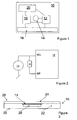
- FIG. 4 A different embodiment of a card not according to the present invention is illustrated by figures 4 and 5 .
- the card 10 comprises, at one edge, 32, a row of light emitters 40.
- the light emitters 40 are controlled by a receiver or controller 12 which receives information from a bending estimator/sensor 14.
- the bending estimator 14 may be a piezo electric element, a strain gauge, a pressure sensitive resistor or the like.
- This estimator 12 is provided on or at the side of the base material 22 (normally plastics) of the card 10 in order for the estimator 14 to be extended or compressed during bending of the card 10 into or out of the plane of the figure and outputs a signal corresponding to the compression/extension.
- the estimator and controller 12 may, as the light emitters 40, be laminated into or fixed on the surface of the base element 22 of the card 10 as is known in e.g. credit cards.
- the present card 10 is adapted to be held at the edge 34 or close to the edge 34 opposite to the edge 32 and to be "waved". This waving will make the card 10 bend, and this bending will provide information as to the movement of the waving.
- the estimator 14 is positioned close to the edge 34 in that this is the position where the bending will be the largest. Other positions may also be used, even though these will be bent less.
- the information or signal from the estimator 14 is fed to the receiver 12 which may then, also based on a timing circuit provided therein, determine either the degree of bending or the position of the edge 32. It is clear that the bending of the card 10 combined with the period of time having elapsed since e.g. a turning point in a reciprocal, waving movement, will point to the position of the edge 32.
- the receiver will be able to both estimate the movement of the edge 32 as well as the actual position of the edge 32 and the light emitters 40.
- the controller 12 When wishing to provide information using light emitted by the emitters 40, the controller 12 has therein information relating to a 2D image or the like which is to be provided.
- This image may be a picture, photo, or text. Any type of 2D information may be provided.
- the controller 12 forwards information or signals to the light emitters 40 corresponding to the position of the edge 32 in the reciprocal movement. This information is used by the controller 12 to forward the correct part of the 2D information to the emitters 40 in order for the resulting provided information to correspond to the 2D information.
- This position determination is relatively important in that the overall image seen would otherwise jump from passing to passing of the reciprocal movement.
- the controller 12 tracks the movement of the edge 32 and adapts the total reciprocal distance to the width of the 2D information in order to be able to present all of the 2D information.
- the 2D information may require (in order to have e.g. the correct resolution or the like) a minimum waving distance. If the present waving does not obtain this distance, the controller may decide to provide only a part of the 2D information. Thus, the text "Mickey is a mouse” may be provided, if the minimum distance is obtained, but only "Mickey” or “Mickey is a” is obtained if smaller distances are obtained during the waving. The same may be the situation with an image.
- the 2D information may scroll over the "surface" or "display” generated by the reciprocating movement of the emitters 40.
- This scrolling may be vertical, as the credits at the end of a movie, or horizontal as a ticker tape display displaying e.g. stock quotes.
- This embodiment may be altered to the situation where not only the relative position of the edge 32 in relation to e.g. the edge 34 is tracked but the actual position of the edge 32, whereby waving the card 10 a small distance and providing "Mickey” and then moving the card in the direction from the "M” to the “y” will make the controller provide "is a” instead, and further movement in that direction will provide the "mouse”.
- a small distance of the waving may be compensated for by a movement of the card 10 in that direction while still waving the smaller distance.
- the extent along the width W of the row of light emitters of the information provided may be varied to take into account the actual distance of the waving.
- the 2D information to be provided should have a certain relation between the direction of W and that perpendicular thereto, a smaller distance of waving may reduce the extent of the provided information along W. Waving a longer distance may make the controller 12 increase the number of light emitters used so as to also increase the extent of the information (such as an image) along the direction of W.
- the controller 12 may alter the font size for the text to be fully represented over the actual distance waved. Waving a larger distance will then make the font size increase.
- the card 10 is also adapted to output a sound.
- the controller 12 may then hold information relating to the sound.
- some bending estimators such as the piezo electric crystal, may be able to also output sound if receiving a corresponding signal.
- the bending estimator 14 may also be used for receiving a signal from the controller 12 and for outputting a corresponding sound. In order to be able to use the estimator 14 for both purposes, it may be desired to only enable the sound outputting action when no bending and light providing takes place.
- FIG. 5 illustrates the waving/bending seen from above.
- the card 10 is illustrated in one extreme position 36, and the other extreme position is illustrated at 38.
- the distance travelled by the edge 32 may be seen as that along the actual curve C which the edge travels through, or it may be taken as the position along a straight line L between the extreme points 36, 38.
- the controller 12 may correct the timing of transmitting the individual parts of the information to the emitters 40 so as to emulate the providing of the information on a flat screen. Thus, this requires that the controller 12 does not output all parts (in the direction into and out of the plane of figure 5 ) equally spaced along the curve C, but equally spaced along the line L.
- the controller 12 may not provide any information before the card 10 has been waved a few times in order for the controller 12 to obtain knowledge about the waving (distance, bending, velocity, acceleration or the like) and to determine how to provide the information at different positions of the movement. Otherwise, or in addition, the controller 12 may be adapted to adapt to changes in waving distance so as to alter the information provided during waving.
- controller 12 may provide the information when moving only in one direction (up-down or down-up in Figure 5 ) or it may provide information in both directions.
- any number of rows of light emitters may be used.
- any type of light emitter 40 may be used (LED, laser, VXEL or the like).
- monochrome light emitters 40 may be used, such as mixed with other emitters of other colours, or light emitters may be used being able to output varying colours.
- the card may be provided with multiple sets of estimator 14 and emitters 40, such as when the emitters 40 of another set is provided at another edge, such as the edge 34, and the estimator 14 relating to that set of emitters 40 is provided oppositely, that is, close to the edge 32.
- the two different sets may be used for providing two different messages or information.
- two different controllers 12 may be provided, or the controller 12 may decide which set to use by determining which estimator 14 detects the largest bending.
- 3D images or information may be provided by providing emitting means in different distances from the edge 32.
- a plurality of 2D information is to be provided, one for each set of emitting means - i.e. one for each "depth" for which information is available.
- These additional emitting means may be provided at a distance from the edge 32 on a side surface of the card 10 or inside the card, if the base material thereof is translucent.
- the controller 12 may be pre-set for any type of information or may be able to output only predetermined information.
- the controller 12 may be able to alter the information provided in any suitable manner, such as stochastically or sequentially changing between information stored therein or by communicating with external equipment adapted to enter the information to be provided into the controller 12. This communication may be wireless or via a wire.
- the card 10 may comprise a keyboard, such as keyboard of switches as illustrated in Figure 3 .
- the card 10 may comprise an optical sensor 42 connected to the controller 12.
- the optical sensor 42 may be exposed to e.g. a computer monitor which is operated to modulate radiation emitted thereby in order to transmit information to the controller 12 via the sensor 42.
- all other types of information transfer may be used, such as via the magnetic strip 18, RFID, Bluetooth, Wireless Ethernet or any other standard.
- these methods may be used for controlling a mode of operation of the controller 12 or may be used for entering into the controller 12 information which is desired provided by the emitters 40.
Landscapes
- Engineering & Computer Science (AREA)
- General Physics & Mathematics (AREA)
- Physics & Mathematics (AREA)
- Microelectronics & Electronic Packaging (AREA)
- Theoretical Computer Science (AREA)
- Computer Hardware Design (AREA)
- Business, Economics & Management (AREA)
- Accounting & Taxation (AREA)
- General Business, Economics & Management (AREA)
- Strategic Management (AREA)
- Computer Networks & Wireless Communication (AREA)
- Computer Security & Cryptography (AREA)
- Credit Cards Or The Like (AREA)
- Measurement Of The Respiration, Hearing Ability, Form, And Blood Characteristics Of Living Organisms (AREA)
- Power Sources (AREA)
- Financial Or Insurance-Related Operations Such As Payment And Settlement (AREA)
- Control Of Vending Devices And Auxiliary Devices For Vending Devices (AREA)
Priority Applications (1)
| Application Number | Priority Date | Filing Date | Title |
|---|---|---|---|
| EP11188215.5A EP2423858B1 (en) | 2007-02-28 | 2008-02-27 | An electronic payment, information, or ID card with a deformation sensing means |
Applications Claiming Priority (2)
| Application Number | Priority Date | Filing Date | Title |
|---|---|---|---|
| US90383407P | 2007-02-28 | 2007-02-28 | |
| PCT/EP2008/052377 WO2008104567A1 (en) | 2007-02-28 | 2008-02-27 | An electronic payment, information, or id card with a deformation sensing means |
Related Child Applications (1)
| Application Number | Title | Priority Date | Filing Date |
|---|---|---|---|
| EP11188215.5A Division EP2423858B1 (en) | 2007-02-28 | 2008-02-27 | An electronic payment, information, or ID card with a deformation sensing means |
Publications (2)
| Publication Number | Publication Date |
|---|---|
| EP2115666A1 EP2115666A1 (en) | 2009-11-11 |
| EP2115666B1 true EP2115666B1 (en) | 2011-11-09 |
Family
ID=38535486
Family Applications (2)
| Application Number | Title | Priority Date | Filing Date |
|---|---|---|---|
| EP11188215.5A Active EP2423858B1 (en) | 2007-02-28 | 2008-02-27 | An electronic payment, information, or ID card with a deformation sensing means |
| EP08717184A Active EP2115666B1 (en) | 2007-02-28 | 2008-02-27 | Electronic payment, information, or id card with a deformation sensing means |
Family Applications Before (1)
| Application Number | Title | Priority Date | Filing Date |
|---|---|---|---|
| EP11188215.5A Active EP2423858B1 (en) | 2007-02-28 | 2008-02-27 | An electronic payment, information, or ID card with a deformation sensing means |
Country Status (15)
| Country | Link |
|---|---|
| US (1) | US8061622B2 (OSRAM) |
| EP (2) | EP2423858B1 (OSRAM) |
| JP (3) | JP5770974B2 (OSRAM) |
| KR (2) | KR101554942B1 (OSRAM) |
| CN (1) | CN101647032B (OSRAM) |
| AT (1) | ATE533123T1 (OSRAM) |
| AU (1) | AU2008220772B2 (OSRAM) |
| BR (1) | BRPI0808147B1 (OSRAM) |
| CA (2) | CA2678793C (OSRAM) |
| DK (1) | DK2115666T3 (OSRAM) |
| ES (1) | ES2374333T3 (OSRAM) |
| MY (1) | MY151768A (OSRAM) |
| NZ (1) | NZ579102A (OSRAM) |
| WO (1) | WO2008104567A1 (OSRAM) |
| ZA (1) | ZA200905775B (OSRAM) |
Families Citing this family (34)
| Publication number | Priority date | Publication date | Assignee | Title |
|---|---|---|---|---|
| US8020775B2 (en) * | 2007-12-24 | 2011-09-20 | Dynamics Inc. | Payment cards and devices with enhanced magnetic emulators |
| JP5204676B2 (ja) * | 2009-01-19 | 2013-06-05 | パナソニック株式会社 | 入退場管理システム |
| EP2224378B1 (en) | 2009-02-25 | 2012-08-01 | Ingecom Sàrl | Method for switching an RFID tag from deep sleep to active mode |
| EP2267649A1 (fr) * | 2009-06-12 | 2010-12-29 | Gemalto SA | Dispositif électronique portable à faible consommation électrique |
| WO2011067429A1 (es) * | 2009-12-04 | 2011-06-09 | Servicios Para Medios De Pago, S.A. | Tarjeta inteligente con contactos |
| WO2011090230A1 (ko) * | 2010-01-25 | 2011-07-28 | Kang Min Soo | Led 전원용 압전회로부를 포함하는 전자식 카드 |
| US10693263B1 (en) * | 2010-03-16 | 2020-06-23 | Dynamics Inc. | Systems and methods for audio connectors for powered cards and devices |
| EP2369752A1 (fr) * | 2010-03-22 | 2011-09-28 | Gemalto SA | Dispositif portable avec batterie autonome et interface de communication radiofréquence |
| EP2390823A1 (fr) | 2010-05-31 | 2011-11-30 | Gemalto SA | Carte bancaire avec écran d'affichage |
| EP2393045A1 (fr) | 2010-06-04 | 2011-12-07 | Gemalto SA | Carte bancaire avec écran d'affichage |
| KR101102944B1 (ko) * | 2010-08-31 | 2012-01-10 | 주식회사 지투테크 | 압전회로부를 포함하는 전자식 카드 |
| DE102010052982B4 (de) | 2010-11-30 | 2021-11-25 | Giesecke+Devrient Mobile Security Gmbh | Portabler Datenträger |
| CA2779880C (en) | 2010-12-03 | 2013-06-25 | Pluritag Inc. | Auricular livestock identification tag |
| US8313037B1 (en) * | 2011-07-08 | 2012-11-20 | Thomas David Humphrey | Simulated magnetic stripe card system and method for use with magnetic stripe card reading terminals |
| US10510070B2 (en) | 2011-10-17 | 2019-12-17 | Capital One Services, Llc | System, method, and apparatus for a dynamic transaction card |
| US10223710B2 (en) | 2013-01-04 | 2019-03-05 | Visa International Service Association | Wearable intelligent vision device apparatuses, methods and systems |
| US20150012426A1 (en) * | 2013-01-04 | 2015-01-08 | Visa International Service Association | Multi disparate gesture actions and transactions apparatuses, methods and systems |
| JP6083225B2 (ja) * | 2012-12-13 | 2017-02-22 | ソニー株式会社 | カード、情報処理装置および情報処理プログラム |
| CN113850097A (zh) | 2012-12-14 | 2021-12-28 | 艾利丹尼森公司 | 配置为用于直接交互的rfid装置 |
| AU2014253051B2 (en) | 2013-04-12 | 2019-10-03 | Cardlab Aps | A card with an offset field generator |
| AU2014253050B2 (en) | 2013-04-12 | 2019-10-03 | Cardlab Aps | A card, an assembly, a method of assembling the card and a method of outputting information |
| DE102013214020A1 (de) * | 2013-07-17 | 2015-02-19 | Stabilo International Gmbh | Digitaler Stift |
| WO2016136565A1 (ja) * | 2015-02-27 | 2016-09-01 | 株式会社村田製作所 | Rfモジュール及びrfシステム |
| DE102015204018A1 (de) * | 2015-03-05 | 2016-09-08 | Bundesdruckerei Gmbh | Wert- oder Sicherheitsdokument mit einer elektronischen Schaltung und Verfahren zum Herstellen des Wert- oder Sicherheitsdokuments |
| WO2016168394A1 (en) * | 2015-04-14 | 2016-10-20 | Capital One Services, LLC. | A system, method, and apparatus for a dynamic transaction card |
| KR101593680B1 (ko) | 2015-05-13 | 2016-02-15 | 한양대학교 산학협력단 | 압전 소자를 이용한 전력 소자의 열응력 저감 장치 및 그 제조 방법 |
| US10732053B2 (en) | 2015-05-13 | 2020-08-04 | Industry-University Cooperation Foundation Hanyang University | Apparatus for measuring temperature of power device using piezoelectric device, apparatus for reducing thermal stress, and method for manufacturing the same |
| US10339433B2 (en) * | 2015-11-04 | 2019-07-02 | Visa International Service Association | Integrated power source on a payment device |
| GB2547905B (en) | 2016-03-02 | 2021-09-22 | Zwipe As | Fingerprint authorisable device |
| GB2551848A (en) * | 2016-07-01 | 2018-01-03 | Zwipe As | Biometric device with low power usage |
| US10984304B2 (en) | 2017-02-02 | 2021-04-20 | Jonny B. Vu | Methods for placing an EMV chip onto a metal card |
| USD956760S1 (en) * | 2018-07-30 | 2022-07-05 | Lion Credit Card Inc. | Multi EMV chip card |
| GB2584434A (en) * | 2019-05-31 | 2020-12-09 | Advanide Holdings Pte Ltd | Enrolment device for a biometric smart card |
| US12277543B2 (en) * | 2022-08-03 | 2025-04-15 | Capital One Services, Llc | Tone verification of a physical card |
Family Cites Families (22)
| Publication number | Priority date | Publication date | Assignee | Title |
|---|---|---|---|---|
| JPH01196518A (ja) * | 1988-01-30 | 1989-08-08 | Dainippon Printing Co Ltd | センサカード |
| JPH01287535A (ja) * | 1988-05-16 | 1989-11-20 | Minolta Camera Co Ltd | カメラ用情報伝達icカード |
| US5247164A (en) * | 1989-01-26 | 1993-09-21 | Hitachi Maxell, Ltd. | IC card and portable terminal |
| JPH02307792A (ja) | 1989-05-23 | 1990-12-20 | Canon Inc | Icカード |
| FR2728710A1 (fr) | 1994-12-23 | 1996-06-28 | Solaic Sa | Carte electronique comportant un element fonctionnel activable manuellement |
| US5791966A (en) | 1996-02-09 | 1998-08-11 | Noise Toys, Inc. | Rotating toy with electronic display |
| US6244514B1 (en) * | 1998-04-20 | 2001-06-12 | Ayao Wada | Smart card for storage and retrieval of digitally compressed color images |
| JP2001005079A (ja) * | 1999-06-22 | 2001-01-12 | Olympus Optical Co Ltd | 衝撃検出装置 |
| DE19947180A1 (de) | 1999-10-01 | 2001-04-05 | Philips Corp Intellectual Pty | Chipkarte |
| KR100376213B1 (ko) * | 2000-03-04 | 2003-03-15 | 구홍식 | 종합금융정보 전자카드수첩 |
| DE10140662C1 (de) | 2001-08-24 | 2003-03-20 | Orga Kartensysteme Gmbh | Chipkarte mit integriertem Schalter |
| DE10146804A1 (de) * | 2001-09-22 | 2003-04-10 | Philips Corp Intellectual Pty | Verfahren und Schaltungsanordnung zum Ansteuern eines Displays sowie Chipkarte mit Display |
| JP3928082B2 (ja) | 2002-03-08 | 2007-06-13 | 富士通株式会社 | Icカード及びその使用方法 |
| AU2003279502A1 (en) | 2003-01-02 | 2004-07-29 | Gyora Mihaly Pal Benedek | Rotating toy with rotation measurement means |
| DE10342054B4 (de) | 2003-09-11 | 2015-06-03 | Giesecke & Devrient Gmbh | Kartenförmiger Datenträger |
| US7681232B2 (en) | 2004-03-08 | 2010-03-16 | Cardlab Aps | Credit card and a secured data activation system |
| JP2005293485A (ja) * | 2004-04-05 | 2005-10-20 | Nippon Telegr & Teleph Corp <Ntt> | Icタグ |
| JP2006134086A (ja) * | 2004-11-05 | 2006-05-25 | Alps Electric Co Ltd | 指紋センサ付きicカード |
| US7347381B2 (en) * | 2004-12-16 | 2008-03-25 | Pitney Bowes Inc. | Secure radio frequency identification documents |
| JP2006276967A (ja) * | 2005-03-28 | 2006-10-12 | Renesas Technology Corp | 半導体装置 |
| JP2006300749A (ja) * | 2005-04-21 | 2006-11-02 | Denso Corp | ノックセンサ |
| ATE438901T1 (de) * | 2006-03-30 | 2009-08-15 | Nxp Bv | Datenträger mit dehnungsmessung |
-
2008
- 2008-02-27 KR KR1020147027036A patent/KR101554942B1/ko active Active
- 2008-02-27 AT AT08717184T patent/ATE533123T1/de active
- 2008-02-27 CN CN200880006335.7A patent/CN101647032B/zh not_active Expired - Fee Related
- 2008-02-27 KR KR1020097020302A patent/KR101593105B1/ko not_active Expired - Fee Related
- 2008-02-27 NZ NZ579102A patent/NZ579102A/en not_active IP Right Cessation
- 2008-02-27 EP EP11188215.5A patent/EP2423858B1/en active Active
- 2008-02-27 ES ES08717184T patent/ES2374333T3/es active Active
- 2008-02-27 AU AU2008220772A patent/AU2008220772B2/en not_active Ceased
- 2008-02-27 JP JP2009551198A patent/JP5770974B2/ja active Active
- 2008-02-27 US US12/086,414 patent/US8061622B2/en not_active Expired - Fee Related
- 2008-02-27 CA CA2678793A patent/CA2678793C/en not_active Expired - Fee Related
- 2008-02-27 DK DK08717184.9T patent/DK2115666T3/da active
- 2008-02-27 EP EP08717184A patent/EP2115666B1/en active Active
- 2008-02-27 WO PCT/EP2008/052377 patent/WO2008104567A1/en not_active Ceased
- 2008-02-27 CA CA2923790A patent/CA2923790C/en not_active Expired - Fee Related
- 2008-02-27 MY MYPI20093525 patent/MY151768A/en unknown
- 2008-02-27 BR BRPI0808147A patent/BRPI0808147B1/pt not_active IP Right Cessation
-
2009
- 2009-08-19 ZA ZA2009/05775A patent/ZA200905775B/en unknown
-
2013
- 2013-07-01 JP JP2013137852A patent/JP2013242885A/ja active Pending
-
2015
- 2015-03-30 JP JP2015067954A patent/JP2015149087A/ja active Pending
Also Published As
| Publication number | Publication date |
|---|---|
| JP5770974B2 (ja) | 2015-08-26 |
| KR101554942B1 (ko) | 2015-09-22 |
| AU2008220772A1 (en) | 2008-09-04 |
| BRPI0808147A2 (pt) | 2014-07-01 |
| KR101593105B1 (ko) | 2016-02-11 |
| EP2423858B1 (en) | 2016-08-03 |
| AU2008220772B2 (en) | 2013-06-27 |
| CA2678793A1 (en) | 2008-09-04 |
| HK1138663A1 (en) | 2010-08-27 |
| KR20140131552A (ko) | 2014-11-13 |
| EP2115666A1 (en) | 2009-11-11 |
| NZ579102A (en) | 2011-10-28 |
| BRPI0808147B1 (pt) | 2019-01-29 |
| CA2678793C (en) | 2016-05-24 |
| EP2423858A1 (en) | 2012-02-29 |
| ATE533123T1 (de) | 2011-11-15 |
| CN101647032B (zh) | 2013-01-23 |
| CA2923790C (en) | 2018-08-14 |
| ES2374333T3 (es) | 2012-02-15 |
| DK2115666T3 (da) | 2012-02-27 |
| KR20100014653A (ko) | 2010-02-10 |
| WO2008104567A1 (en) | 2008-09-04 |
| US20100320274A1 (en) | 2010-12-23 |
| JP2015149087A (ja) | 2015-08-20 |
| JP2010520522A (ja) | 2010-06-10 |
| CN101647032A (zh) | 2010-02-10 |
| CA2923790A1 (en) | 2008-09-04 |
| US8061622B2 (en) | 2011-11-22 |
| ZA200905775B (en) | 2018-11-28 |
| MY151768A (en) | 2014-07-14 |
| JP2013242885A (ja) | 2013-12-05 |
Similar Documents
| Publication | Publication Date | Title |
|---|---|---|
| EP2115666B1 (en) | Electronic payment, information, or id card with a deformation sensing means | |
| CN208611802U (zh) | 智能卡 | |
| US8876011B2 (en) | Payment card and methods | |
| US8282007B1 (en) | Laminated cards with manual input interfaces | |
| JP2020074129A (ja) | 光パルス及びタッチセンサ式ディスプレイを介して通信するカード及び装置のためのシステム及び方法 | |
| US20170287312A1 (en) | Proximity Monitoring Devices and Methods | |
| US8983444B2 (en) | Method for controlling portable device by using humidity sensor and portable device thereof | |
| CN113850097A (zh) | 配置为用于直接交互的rfid装置 | |
| CN112164608B (zh) | 电子设备、其控制方法和控制装置 | |
| HK1138663B (en) | Electronic payment, information, or id card with a deformation sensing means | |
| CA2773813A1 (en) | Portable electronic device and method of controlling same | |
| JP2012141911A (ja) | 表示機能付きicカード | |
| US20120274545A1 (en) | Portable electronic device and method of controlling same | |
| KR20170139483A (ko) | 지문 검출 장치를 포함하는 스마트카드 | |
| TW202518185A (zh) | 用於控制可變物理參數的控制裝置及功能裝置及方法 |
Legal Events
| Date | Code | Title | Description |
|---|---|---|---|
| PUAI | Public reference made under article 153(3) epc to a published international application that has entered the european phase |
Free format text: ORIGINAL CODE: 0009012 |
|
| 17P | Request for examination filed |
Effective date: 20090408 |
|
| AK | Designated contracting states |
Kind code of ref document: A1 Designated state(s): AT BE BG CH CY CZ DE DK EE ES FI FR GB GR HR HU IE IS IT LI LT LU LV MC MT NL NO PL PT RO SE SI SK TR |
|
| DAX | Request for extension of the european patent (deleted) | ||
| 17Q | First examination report despatched |
Effective date: 20100708 |
|
| REG | Reference to a national code |
Ref country code: HK Ref legal event code: DE Ref document number: 1138663 Country of ref document: HK |
|
| GRAP | Despatch of communication of intention to grant a patent |
Free format text: ORIGINAL CODE: EPIDOSNIGR1 |
|
| RIC1 | Information provided on ipc code assigned before grant |
Ipc: G06K 19/077 20060101AFI20110505BHEP Ipc: G07F 7/08 20060101ALI20110505BHEP |
|
| GRAS | Grant fee paid |
Free format text: ORIGINAL CODE: EPIDOSNIGR3 |
|
| GRAA | (expected) grant |
Free format text: ORIGINAL CODE: 0009210 |
|
| AK | Designated contracting states |
Kind code of ref document: B1 Designated state(s): AT BE BG CH CY CZ DE DK EE ES FI FR GB GR HR HU IE IS IT LI LT LU LV MC MT NL NO PL PT RO SE SI SK TR |
|
| REG | Reference to a national code |
Ref country code: GB Ref legal event code: FG4D |
|
| REG | Reference to a national code |
Ref country code: CH Ref legal event code: EP |
|
| REG | Reference to a national code |
Ref country code: IE Ref legal event code: FG4D |
|
| REG | Reference to a national code |
Ref country code: DE Ref legal event code: R096 Ref document number: 602008011258 Country of ref document: DE Effective date: 20120105 |
|
| REG | Reference to a national code |
Ref country code: ES Ref legal event code: FG2A Ref document number: 2374333 Country of ref document: ES Kind code of ref document: T3 Effective date: 20120215 Ref country code: NL Ref legal event code: T3 |
|
| REG | Reference to a national code |
Ref country code: DK Ref legal event code: T3 |
|
| REG | Reference to a national code |
Ref country code: SE Ref legal event code: TRGR |
|
| REG | Reference to a national code |
Ref country code: CH Ref legal event code: NV Representative=s name: MICHELI & CIE SA |
|
| LTIE | Lt: invalidation of european patent or patent extension |
Effective date: 20111109 |
|
| PG25 | Lapsed in a contracting state [announced via postgrant information from national office to epo] |
Ref country code: LT Free format text: LAPSE BECAUSE OF FAILURE TO SUBMIT A TRANSLATION OF THE DESCRIPTION OR TO PAY THE FEE WITHIN THE PRESCRIBED TIME-LIMIT Effective date: 20111109 Ref country code: IS Free format text: LAPSE BECAUSE OF FAILURE TO SUBMIT A TRANSLATION OF THE DESCRIPTION OR TO PAY THE FEE WITHIN THE PRESCRIBED TIME-LIMIT Effective date: 20120309 Ref country code: NO Free format text: LAPSE BECAUSE OF FAILURE TO SUBMIT A TRANSLATION OF THE DESCRIPTION OR TO PAY THE FEE WITHIN THE PRESCRIBED TIME-LIMIT Effective date: 20120209 |
|
| PG25 | Lapsed in a contracting state [announced via postgrant information from national office to epo] |
Ref country code: PT Free format text: LAPSE BECAUSE OF FAILURE TO SUBMIT A TRANSLATION OF THE DESCRIPTION OR TO PAY THE FEE WITHIN THE PRESCRIBED TIME-LIMIT Effective date: 20120309 Ref country code: SI Free format text: LAPSE BECAUSE OF FAILURE TO SUBMIT A TRANSLATION OF THE DESCRIPTION OR TO PAY THE FEE WITHIN THE PRESCRIBED TIME-LIMIT Effective date: 20111109 Ref country code: PL Free format text: LAPSE BECAUSE OF FAILURE TO SUBMIT A TRANSLATION OF THE DESCRIPTION OR TO PAY THE FEE WITHIN THE PRESCRIBED TIME-LIMIT Effective date: 20111109 Ref country code: LV Free format text: LAPSE BECAUSE OF FAILURE TO SUBMIT A TRANSLATION OF THE DESCRIPTION OR TO PAY THE FEE WITHIN THE PRESCRIBED TIME-LIMIT Effective date: 20111109 Ref country code: GR Free format text: LAPSE BECAUSE OF FAILURE TO SUBMIT A TRANSLATION OF THE DESCRIPTION OR TO PAY THE FEE WITHIN THE PRESCRIBED TIME-LIMIT Effective date: 20120210 Ref country code: HR Free format text: LAPSE BECAUSE OF FAILURE TO SUBMIT A TRANSLATION OF THE DESCRIPTION OR TO PAY THE FEE WITHIN THE PRESCRIBED TIME-LIMIT Effective date: 20111109 |
|
| PG25 | Lapsed in a contracting state [announced via postgrant information from national office to epo] |
Ref country code: CY Free format text: LAPSE BECAUSE OF FAILURE TO SUBMIT A TRANSLATION OF THE DESCRIPTION OR TO PAY THE FEE WITHIN THE PRESCRIBED TIME-LIMIT Effective date: 20111109 |
|
| REG | Reference to a national code |
Ref country code: HK Ref legal event code: GR Ref document number: 1138663 Country of ref document: HK |
|
| PG25 | Lapsed in a contracting state [announced via postgrant information from national office to epo] |
Ref country code: SK Free format text: LAPSE BECAUSE OF FAILURE TO SUBMIT A TRANSLATION OF THE DESCRIPTION OR TO PAY THE FEE WITHIN THE PRESCRIBED TIME-LIMIT Effective date: 20111109 Ref country code: CZ Free format text: LAPSE BECAUSE OF FAILURE TO SUBMIT A TRANSLATION OF THE DESCRIPTION OR TO PAY THE FEE WITHIN THE PRESCRIBED TIME-LIMIT Effective date: 20111109 Ref country code: BG Free format text: LAPSE BECAUSE OF FAILURE TO SUBMIT A TRANSLATION OF THE DESCRIPTION OR TO PAY THE FEE WITHIN THE PRESCRIBED TIME-LIMIT Effective date: 20120209 Ref country code: EE Free format text: LAPSE BECAUSE OF FAILURE TO SUBMIT A TRANSLATION OF THE DESCRIPTION OR TO PAY THE FEE WITHIN THE PRESCRIBED TIME-LIMIT Effective date: 20111109 |
|
| PG25 | Lapsed in a contracting state [announced via postgrant information from national office to epo] |
Ref country code: RO Free format text: LAPSE BECAUSE OF FAILURE TO SUBMIT A TRANSLATION OF THE DESCRIPTION OR TO PAY THE FEE WITHIN THE PRESCRIBED TIME-LIMIT Effective date: 20111109 |
|
| PLBE | No opposition filed within time limit |
Free format text: ORIGINAL CODE: 0009261 |
|
| STAA | Information on the status of an ep patent application or granted ep patent |
Free format text: STATUS: NO OPPOSITION FILED WITHIN TIME LIMIT |
|
| PG25 | Lapsed in a contracting state [announced via postgrant information from national office to epo] |
Ref country code: MC Free format text: LAPSE BECAUSE OF NON-PAYMENT OF DUE FEES Effective date: 20120229 |
|
| 26N | No opposition filed |
Effective date: 20120810 |
|
| REG | Reference to a national code |
Ref country code: IE Ref legal event code: MM4A |
|
| REG | Reference to a national code |
Ref country code: DE Ref legal event code: R097 Ref document number: 602008011258 Country of ref document: DE Effective date: 20120810 |
|
| PG25 | Lapsed in a contracting state [announced via postgrant information from national office to epo] |
Ref country code: IE Free format text: LAPSE BECAUSE OF NON-PAYMENT OF DUE FEES Effective date: 20120227 |
|
| PG25 | Lapsed in a contracting state [announced via postgrant information from national office to epo] |
Ref country code: FI Free format text: LAPSE BECAUSE OF FAILURE TO SUBMIT A TRANSLATION OF THE DESCRIPTION OR TO PAY THE FEE WITHIN THE PRESCRIBED TIME-LIMIT Effective date: 20111109 |
|
| PG25 | Lapsed in a contracting state [announced via postgrant information from national office to epo] |
Ref country code: MT Free format text: LAPSE BECAUSE OF FAILURE TO SUBMIT A TRANSLATION OF THE DESCRIPTION OR TO PAY THE FEE WITHIN THE PRESCRIBED TIME-LIMIT Effective date: 20111109 |
|
| PG25 | Lapsed in a contracting state [announced via postgrant information from national office to epo] |
Ref country code: TR Free format text: LAPSE BECAUSE OF FAILURE TO SUBMIT A TRANSLATION OF THE DESCRIPTION OR TO PAY THE FEE WITHIN THE PRESCRIBED TIME-LIMIT Effective date: 20111109 |
|
| PG25 | Lapsed in a contracting state [announced via postgrant information from national office to epo] |
Ref country code: HU Free format text: LAPSE BECAUSE OF FAILURE TO SUBMIT A TRANSLATION OF THE DESCRIPTION OR TO PAY THE FEE WITHIN THE PRESCRIBED TIME-LIMIT Effective date: 20080227 |
|
| REG | Reference to a national code |
Ref country code: FR Ref legal event code: PLFP Year of fee payment: 8 |
|
| REG | Reference to a national code |
Ref country code: FR Ref legal event code: PLFP Year of fee payment: 9 |
|
| REG | Reference to a national code |
Ref country code: FR Ref legal event code: PLFP Year of fee payment: 10 |
|
| REG | Reference to a national code |
Ref country code: FR Ref legal event code: PLFP Year of fee payment: 11 |
|
| PGFP | Annual fee paid to national office [announced via postgrant information from national office to epo] |
Ref country code: GB Payment date: 20200218 Year of fee payment: 13 Ref country code: DE Payment date: 20200220 Year of fee payment: 13 Ref country code: AT Payment date: 20200219 Year of fee payment: 13 Ref country code: NL Payment date: 20200218 Year of fee payment: 13 Ref country code: ES Payment date: 20200302 Year of fee payment: 13 |
|
| PGFP | Annual fee paid to national office [announced via postgrant information from national office to epo] |
Ref country code: LU Payment date: 20200218 Year of fee payment: 13 |
|
| PGFP | Annual fee paid to national office [announced via postgrant information from national office to epo] |
Ref country code: FR Payment date: 20200217 Year of fee payment: 13 |
|
| REG | Reference to a national code |
Ref country code: DE Ref legal event code: R119 Ref document number: 602008011258 Country of ref document: DE |
|
| REG | Reference to a national code |
Ref country code: AT Ref legal event code: MM01 Ref document number: 533123 Country of ref document: AT Kind code of ref document: T Effective date: 20210227 |
|
| GBPC | Gb: european patent ceased through non-payment of renewal fee |
Effective date: 20210227 |
|
| PG25 | Lapsed in a contracting state [announced via postgrant information from national office to epo] |
Ref country code: LU Free format text: LAPSE BECAUSE OF NON-PAYMENT OF DUE FEES Effective date: 20210227 Ref country code: AT Free format text: LAPSE BECAUSE OF NON-PAYMENT OF DUE FEES Effective date: 20210227 |
|
| PGFP | Annual fee paid to national office [announced via postgrant information from national office to epo] |
Ref country code: CH Payment date: 20210827 Year of fee payment: 14 |
|
| REG | Reference to a national code |
Ref country code: NL Ref legal event code: MM Effective date: 20210301 |
|
| PG25 | Lapsed in a contracting state [announced via postgrant information from national office to epo] |
Ref country code: NL Free format text: LAPSE BECAUSE OF NON-PAYMENT OF DUE FEES Effective date: 20210301 |
|
| PG25 | Lapsed in a contracting state [announced via postgrant information from national office to epo] |
Ref country code: DE Free format text: LAPSE BECAUSE OF NON-PAYMENT OF DUE FEES Effective date: 20210901 Ref country code: GB Free format text: LAPSE BECAUSE OF NON-PAYMENT OF DUE FEES Effective date: 20210227 Ref country code: FR Free format text: LAPSE BECAUSE OF NON-PAYMENT OF DUE FEES Effective date: 20210228 |
|
| REG | Reference to a national code |
Ref country code: ES Ref legal event code: FD2A Effective date: 20220513 |
|
| PG25 | Lapsed in a contracting state [announced via postgrant information from national office to epo] |
Ref country code: ES Free format text: LAPSE BECAUSE OF NON-PAYMENT OF DUE FEES Effective date: 20210228 |
|
| REG | Reference to a national code |
Ref country code: CH Ref legal event code: PL |
|
| PGFP | Annual fee paid to national office [announced via postgrant information from national office to epo] |
Ref country code: SE Payment date: 20220822 Year of fee payment: 15 |
|
| PGFP | Annual fee paid to national office [announced via postgrant information from national office to epo] |
Ref country code: BE Payment date: 20220819 Year of fee payment: 15 |
|
| PG25 | Lapsed in a contracting state [announced via postgrant information from national office to epo] |
Ref country code: LI Free format text: LAPSE BECAUSE OF NON-PAYMENT OF DUE FEES Effective date: 20220228 Ref country code: CH Free format text: LAPSE BECAUSE OF NON-PAYMENT OF DUE FEES Effective date: 20220228 |
|
| REG | Reference to a national code |
Ref country code: SE Ref legal event code: EUG |
|
| REG | Reference to a national code |
Ref country code: BE Ref legal event code: MM Effective date: 20230228 |
|
| PG25 | Lapsed in a contracting state [announced via postgrant information from national office to epo] |
Ref country code: SE Free format text: LAPSE BECAUSE OF NON-PAYMENT OF DUE FEES Effective date: 20230228 |
|
| PG25 | Lapsed in a contracting state [announced via postgrant information from national office to epo] |
Ref country code: BE Free format text: LAPSE BECAUSE OF NON-PAYMENT OF DUE FEES Effective date: 20230228 |
|
| PGFP | Annual fee paid to national office [announced via postgrant information from national office to epo] |
Ref country code: IT Payment date: 20240219 Year of fee payment: 17 |
|
| PGFP | Annual fee paid to national office [announced via postgrant information from national office to epo] |
Ref country code: DK Payment date: 20250205 Year of fee payment: 18 |