EP2114065A2 - Farbumwandlungsvorrichtung, Bildgebungsvorrichtung, Speichermedium, das das Farbumwandlungsprogramm speichert und Speichermedium, das das Bildgebungsprogramm speichert - Google Patents
Farbumwandlungsvorrichtung, Bildgebungsvorrichtung, Speichermedium, das das Farbumwandlungsprogramm speichert und Speichermedium, das das Bildgebungsprogramm speichert Download PDFInfo
- Publication number
- EP2114065A2 EP2114065A2 EP08011916A EP08011916A EP2114065A2 EP 2114065 A2 EP2114065 A2 EP 2114065A2 EP 08011916 A EP08011916 A EP 08011916A EP 08011916 A EP08011916 A EP 08011916A EP 2114065 A2 EP2114065 A2 EP 2114065A2
- Authority
- EP
- European Patent Office
- Prior art keywords
- hue
- image
- color conversion
- conversion target
- saturation
- Prior art date
- Legal status (The legal status is an assumption and is not a legal conclusion. Google has not performed a legal analysis and makes no representation as to the accuracy of the status listed.)
- Granted
Links
Images




Classifications
-
- H—ELECTRICITY
- H04—ELECTRIC COMMUNICATION TECHNIQUE
- H04N—PICTORIAL COMMUNICATION, e.g. TELEVISION
- H04N1/00—Scanning, transmission or reproduction of documents or the like, e.g. facsimile transmission; Details thereof
- H04N1/46—Colour picture communication systems
- H04N1/56—Processing of colour picture signals
- H04N1/60—Colour correction or control
- H04N1/62—Retouching, i.e. modification of isolated colours only or in isolated picture areas only
- H04N1/622—Retouching, i.e. modification of isolated colours only or in isolated picture areas only with simulation on a subsidiary picture reproducer
-
- H—ELECTRICITY
- H04—ELECTRIC COMMUNICATION TECHNIQUE
- H04N—PICTORIAL COMMUNICATION, e.g. TELEVISION
- H04N1/00—Scanning, transmission or reproduction of documents or the like, e.g. facsimile transmission; Details thereof
- H04N1/40—Picture signal circuits
- H04N1/40012—Conversion of colour to monochrome
Definitions
- the present invention relates to a color conversion apparatus, an imaging apparatus, a storage medium storing a color conversion program, and a storage medium storing an imaging program, and more particularly, to a color conversion apparatus, an imaging apparatus, a storage medium storing a color conversion program, and a storage medium storing an imaging program for converting a color of a displayed image.
- Patent Document 1 Japanese Laid-Open Patent Publication No. 8-293995
- Patent Document 1 Japanese Laid-Open Patent Publication No. 8-293995
- An image processing apparatus disclosed in the Patent Document 1 extracts hue, saturation, and brightness of a pixel corresponding to a position designated by the user, and determines maximum and minimum values of these components. Then, when the user designates a color which is desired to change to, the image processing apparatus converts colors of pixels in a previously determined range into the designated color.
- the image processing apparatus disclosed in the Patent Document 1 sets a minimum value to a maximum value of each of hue, saturation, and brightness of each of pixels corresponding to the plurality of positions as a range to be color-converted.
- the user needs to designate a plurality of positions with respect to an image in performing color conversion, and an operation becomes troublesome. If the user designates only a single position in performing color conversion, a range to be color-converted is a pinpoint, and it is considered that color conversion with respect to an image is hardly performed.
- an object of the present invention is to provide a color conversion apparatus, an imaging apparatus, a storage medium storing a color conversion program, and a storage medium storing an imaging program which are capable of performing color conversion desired by a user with respect to a displayed image in accordance with a simple operation.
- the present invention has the following features to attain the object mentioned above. It is noted that reference characters, step numbers, and supplementary explanations in parentheses are merely provided to facilitate the understanding of the present invention in relation to the later-described embodiment, rather than limiting the scope of the present invention in any way.
- a first aspect is a color conversion apparatus (1) for performing color conversion of an image displayed on a display device (12) in accordance with an output from a pointing device (13) for outputting an input position (TP).
- the color conversion apparatus comprises display image display control means (a CPU 31 executing a step 52, and hereinafter, only a step number is described), input position obtaining means (S54), hue obtaining means (S55, S56), conversion target range setting means (S56), and color conversion means (S57).
- the display image display control means is means for displaying a predetermined display image on the display device.
- the input position obtaining means is means for obtaining the input position from the pointing device (Da).
- the hue obtaining means is means for obtaining a hue of the display image corresponding to the input position obtained by the input position obtaining means.
- the conversion target range setting means is means for setting a predetermined hue range having the hue obtained by the hue obtaining means at a center thereof as a conversion target range (De).
- the color conversion means is means for changing at least one of saturation, brightness, and hue with respect to a pixel of the display image which has a hue within the conversion target range, and displaying a resultant image on the display device.
- the pointing device is an input device for designating an input position or coordinates on a screen, and realized, for example, by a touch panel, a mouse, a trackpad, a trackball, a pen tablet, a joystick, a system for detecting a screen position at which a housing of a game controller is pointed, and the like.
- a method for the color conversion means to change at least one of saturation, brightness, and hue may be realized by changing a data table (e.g. a conversion table) in which saturation, brightness, and hue for displaying the display image are defined, data indicative of at least one of saturation, brightness, and hue among image data indicative of the display image may be directly changed, or at least one of saturation, brightness, and hue may be changed by another method.
- a data table e.g. a conversion table
- the display image display control means may display on the display device the display image which is converted into an achromatic image by decreasing saturation of all pixels of a chromatic original image.
- the color conversion means returns saturation of a pixel of the display image which has a hue within the conversion target range to saturation in the original image, and displays a resultant image on the display device.
- the color conversion means may change saturation of a pixel having a hue within the conversion target range which is away from a center of the conversion target range while gradually decreasing a rate of returning the saturation of the pixel to saturation in the original image as the hue is away from the center ( FIG. 5 ).
- the color conversion means may change saturation of a pixel having a hue within the conversion target range which is away from the center of the conversion target range while linearly decreasing a rate of returning the saturation of the pixel to saturation in the original image from 100% to 0% as the hue is away from the center ( FIG. 5 ).
- the hue obtaining means may obtain a hue of the display image corresponding to each of the input positions.
- the conversion target range setting means sets predetermined hue ranges having the hues obtained by the hue obtaining means at centers thereof, respectively, as a first conversion target range and a second conversion target range.
- the color conversion means changes at least one of saturation, brightness, and hue with respect to a pixel of the display image which has a hue within the first conversion target range and a pixel of the display image which has a hue within the second conversion target range, and displays a resultant image on the display device ( FIG. 7 ).
- the color conversion means may change at least one of saturation and brightness of a pixel having a hue within the first conversion target range which is away from the center of the first conversion target range while gradually decreasing a rate of changing at least one of the saturation and the brightness of the pixel as the hue is away from the center.
- the color conversion means may change at least one of saturation and brightness of a pixel having a hue within the second conversion target range which is away from the center of the second conversion target range while gradually decreasing a rate of changing at least one of the saturation and the brightness of the pixel as the hue is away from the center.
- the color conversion means selects a higher rate among a rate of changing at least one of saturation and brightness for the first conversion target range and a rate of changing at least one of saturation and brightness for the second conversion target range, and changes at least one of saturation and brightness of a pixel having a hue within an overlapping range ( FIG. 7 ).
- the color conversion means may change at least one of saturation and brightness of a pixel having a hue within the first conversion target range which is away from the center of the first conversion target range while gradually decreasing a rate of changing at least one of the saturation and the brightness of the pixel as the hue is away from the center.
- the color conversion means may change at least one of saturation and brightness of a pixel having a hue within the second conversion target range which is away from the center of the second conversion target range while gradually decreasing a rate of changing at least one of the saturation and the brightness of the pixel as the hue is away from the center.
- the color conversion means changes a rate of changing at least one of saturation and brightness of a pixel having a hue within an overlapping range in a curved manner such that a center of the overlapping range becomes minimum.
- the color conversion apparatus may further comprise imaging means (23, 25) .
- the imaging means is means for taking an image of a vicinity of the color conversion apparatus.
- the display image display control means may display an image taken by the imaging means as the display image on the display device in real time.
- the display image display control means may display a chromatic original image as the display image on the display device.
- the color conversion means changes a hue of a pixel of the display image which has the hue within the conversion target range so as to be close to a conversion target hue, and displays a resultant image on the display device.
- the color conversion means changes a hue of a pixel having the hue which is within the conversion target range and away from a center of the conversion target range so as to be close to the conversion target hue as the hue is close to the center ( FIG. 11 ).
- the hue obtaining means when the input position obtaining means obtains a first input position, the hue obtaining means obtains a hue at the first input position in the display image as a first hue.
- the color conversion means changes, among each pixel of the display image, a hue of a pixel having the hue within a first conversion target range having at a center thereof the first hue obtained by the hue obtaining means so as to be close to a first conversion target hue, and displays a resultant image on the display device.
- the hue obtaining means obtains a hue at the second input position in the display image as a second hue.
- the color conversion means changes, among each pixel of the display image, a hue of a pixel having the hue within a second conversion target range having at a center thereof the second hue so as to be close to a second conversion target hue, and displays a resultant image on the display device.
- the color conversion means changes, with respect to a pixel having a hue within the overlapping range, a hue of the pixel which is changed for the first conversion target range so as to be close to the second conversion target hue based on the changed hue.
- the first conversion target hue and the second conversion target hue may be the same as each other or may be different from each other.
- the color conversion means sets the conversion target hue based on a hue of a pixel at the input position which is displayed on the display device immediately before the input position is obtained.
- the color conversion means sets the second conversion target hue based on a hue of a pixel at the second input position which is displayed on the display device immediately before the second input position is obtained.
- the color conversion means sequentially changes the conversion target hue as time passes, and displays a resultant image on the display device ( FIG. 10 ).
- a fifteenth aspect is an imaging apparatus for converting a color of a taken image displayed on a display device in accordance with an output from a pointing device for outputting an input position.
- the imaging apparatus comprises imaging means, taken image display control means, input position obtaining means, hue obtaining means, conversion target range setting means, and color conversion means.
- the imaging means is means for taking an image of a vicinity of the imaging apparatus.
- the taken image display control means is means for displaying a taken image taken by the imaging means on the display device in real time.
- the input position obtaining means is means for obtaining the input position from the pointing device.
- the hue obtaining means is means for obtaining a hue of the taken image corresponding to the input position obtained by the input position obtaining means.
- the conversion target range setting means is means for setting a predetermined hue range having the hue obtained by the hue obtaining means at a center thereof as a conversion target range.
- the color conversion means is means for changing at least one of saturation, brightness, hue with respect to a pixel of the taken image which has a hue within the conversion target range, and displaying a resultant image on the display device.
- a sixteenth aspect is a computer-readable storage medium storing an imaging program executed by a computer (31) for converting a color of a taken image displayed on a display device in accordance with an output from a pointing device for outputting an input position.
- the imaging program causes the computer to operate as: taken image display control means; input position obtaining means; hue obtaining means; conversion target range settingmeans; andcolorconversionmeans.
- the taken image display control means is means for displaying a taken image taken by imaging means for taking an image of a vicinity on the display device in real time.
- the input position obtaining means is means for obtaining the input position from the pointing device.
- the hue obtaining means is means for obtaining a hue of the taken image corresponding to the input position obtained by the input position obtaining means.
- the conversion target range setting means is means for setting a predetermined hue range having the hue obtained by the hue obtaining means at a center thereof as a conversion target range.
- the color conversion means is means for changing at least one of saturation, brightness, and hue with respect to a pixel of the taken image which has a hue within the conversion target range, and displaying a resultant image on the display device.
- the user only by the user once performing an operation with respect to the display image displayed on the display device to designate an input position or coordinates using the pointing device, it is possible to perform color conversion of the display image which is desired by the user. Further, when color conversion is performed with a color conversion target limited to only a hue of a pixel overlapping with the input position, it is considered that a significantly limited region (in an extreme case, only a pixel overlapping with the input position) of the display image is color-converted, and color conversion desired by the user cannot be performed. On the other hand, it is rare that the user desires to color-convert only a hue designated by the input position, and generally, the user desires hues adjacent to the hue to some extent to be color conversion targets.
- hues in a predetermined range having the hue at a center thereof are set to a range of a color conversion target.
- hues slightly different from the hue of the pixel overlapping with the touch position can be color conversion targets, thereby enabling color conversion desired by the user to be performed.
- the second aspect only by the user once performing an operation with respect to the achromatic image displayed on the display device to designate a position at which a color desired by the user is originally expressed, it is possible to perform color conversion such that the color is restored in the achromatic image.
- the saturation so as to be gradually decreased with the hue which is set corresponding to the input position as a center
- noise can be reduced in performing color conversion, and it is possible to convert into an image such that color which is originally expressed at the input position is naturally added.
- the fifth aspect when the user designates a plurality of input positions, it is possible to perform color conversion with respect to a hue corresponding to each of the input positions.
- the ninth aspect only by the user once performing an operation with respect to the chromatic image displayed on the display device to designate a position at which a color desired by the user is displayed, it is possible to perform color conversion such that the color designated in the chromatic image is converted so as to be close to a different color (a conversion target hue).
- the tenth aspect by making setting such that, with a hue set in accordance with an input position as a center, an original hue is changed so as to be gradually close to the conversion target hue as being close to the center, noise can be reduced in performing color conversion, and it is possible to convert into an image such that color is naturally changed.
- the eleventh aspect when the user performs an operation of designating a different hue with respect to the display image, it is possible to perform color conversion such that a pixel having each hue is converted so as to be close to the first conversion target hue or the second conversion target hue.
- hue conversion performed with respect to hues within a range where the color conversions overlap with each other can be smoothly connected, and it is possible to convert into an image such that a plurality of color conversion are naturally performed.
- the user when the user performs an operation of designating a different hue with respect to the display image, it is possible to perform color conversion such that a pixel having each hue is converted so as to be close to a different hue.
- the user repeating an operation of designating a position, it is possible to perform color conversion such that the designated color is sequentially changed to a different color.
- the fourteenth aspect it is possible to convert into an image such that a hue set in accordance with an input position is sequentially changed as time passes.
- the imaging apparatus and the storage medium storing the imaging program according to the present invention the same advantageous effects as those of the above color conversion apparatus can be obtained.
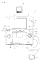
- FIG. 1 is an external view of the game apparatus 1 executing the color conversion program of the present invention.
- a hand-held game apparatus is shown as an example of the game apparatus 1.
- the game apparatus 1 includes a camera, and functions as an imaging apparatus to take an image with the camera, to display the taken image on a screen, and to store data of the taken image.
- the game apparatus 1 is a foldable hand-held game apparatus in an opened state.
- the game apparatus 1 is configured to have such a size as to be held by a user with both hands or one hand.
- the game apparatus 1 includes a lower housing 11 and an upper housing 21.
- the lower housing 11 and the upper housing 21 are connected to each other so as to be capable of being opened or closed (foldable).
- the lower housing 11 and the upper housing 21 are each formed in a plate-like shape of a horizontally long rectangle, and foldably connected to each other at long side portions thereof.
- the user uses the game apparatus 1 in the opened state.
- the user keeps the game apparatus 1 in a closed state.
- the game apparatus 1 in addition to the closed state and the opened state, the game apparatus 1 is capable of maintaining an angle between the lower housing 11 and the upper housing 21 at any angle ranging between the closed state and the opened state by frictional force generated at a connection portion, and the like.
- the upper housing 21 can be stationary at any angle with respect to the lower housing 11.
- a lower LCD (Liquid Crystal Display) 12 is provided in the lower housing 11.
- the lower LCD 12 has a horizontally long shape, and is located such that a long side direction thereof corresponds to a long side direction of the lower housing 11.
- any other display devices such as a display device using an EL (Electro Luminescence), and the like may be used.
- the game apparatus 1 can use a display device of any resolution.
- the lower LCD 12 is used mainly for displaying an image taken by a camera 23 or 25 in real time.
- operation buttons 14A to 14K and a touch panel 13 are provided as input devices. As shown in FIG. 1 , among the operation buttons 14A to 14K, the direction input button 14A, the operation button 14B, the operation button 14C, the operation button 14D, the operation button 14E, the power button 14F, the start button 14G, and the select button 14H are provided on an inner main surface of the lower housing 11 which is located inside when the upper housing 21 and the lower housing 11 are folded.
- the direction input button 14A is used, for example, for a selection operation, and the like.
- the operation buttons 14B to 14E are used, for example, for a determination operation, a cancellation operation, and the like.
- the power button 14F is used for turning on or off the power of the game apparatus 1.
- the direction input button 14A and the power button 14F are provided on the inner main surface of the lower housing 11 and on one of a left side and a right side (on the left side in FIG. 1 ) of the lower LCD 12 provided in the vicinity of a center of the inner main surface of the lower housing 11.
- the operation buttons 14B to 14E, the start button 14G, and the select button 14H are provided on the inner main surface of the lower housing 11 and on the other of the left side and the right side (on the right side in FIG. 1 ) of the lower LCD 12.
- the direction input button 14A, the operation buttons 14B to 14E, the start button 14G, and the select button 14H are used for performing various operations with respect to the game apparatus 1.
- buttons 14F to 14K are omitted in FIG. 1 .
- the L button 14I is provided at a left end of an upper surface of the lower housing 11, and the R button 14J is provided at a right end of the upper surface of the lower housing 11.
- the L button 14I and the R button 14J are used, for example, for performing a photographing instruction operation (a shutter operation) with respect to the game apparatus 1.
- the volume button 14K is provided on a left side surface of the lower housing 11.
- the volume button 14K is used for adjusting volume of speakers of the game apparatus 1.
- the game apparatus 1 further includes the touch panel 13 as another input device in addition to the operation buttons 14A to 14K.
- the touch panel 13 is mounted so as to cover a screen of the lower LCD 12.
- the touch panel 13 is, for example, a resistive film type touch panel.
- the touch panel 13 is not limited to the resistive film type, but any press-type touch panel may be used.
- the touch panel 13 used in the present embodiment has the same resolution (detection accuracy) as that of the lower LCD 12. However, the resolution of the touch panel 13 and the lower LCD 12 may not necessarily be the same as each other.
- an insertion opening (a dotted line shown in FIG. 1 ) is provided in the right side surface of the lower housing 11.
- the insertion opening is capable of accommodating a touch pen 27 which is used for performing an operation with respect to the touch panel 13.
- a touch pen 27 which is used for performing an operation with respect to the touch panel 13.
- an input with respect to the touch panel 13 is usually performed using the touch pen 27, in addition to the touch pen 27, a finger of the user can be used for operating the touch panel 13.
- an insertion opening (indicated by a two-dot chain line in FIG. 1 ) is provided for accommodating a memory card 28.
- a connector (not shown) is provided for electrically connecting the game apparatus 1 to the memory card 28.
- the memory card 28 is, for example, an SD (Secure Digital) memory card, and detachably mounted to the connector.
- the memory card 28 is used, for example, for storing an image taken by the game apparatus 1, and loading an image generated by another apparatus into the game apparatus 1.
- an insertion opening (indicated by a chain line in FIG. 1 ) is provided for accommodating a memory card 29. Inside the insertion opening, a connector (not shown) is provided for electrically connecting the game apparatus 1 to the memory card 29.
- the memory card 29 is a storage medium storing a color conversion program, a game program, and the like, and detachably mounted in the insertion opening provided in the lower housing 11.
- Three LEDs 15A to 15C are mounted to a left side part of the connection portion where the lower housing 11 and the upper housing 21 are connected to each other.
- the game apparatus 1 is capable of performing wireless communication with another apparatus, and the first LED 15A is lit up while wireless communication is established.
- the second LED 15B is lit up while the game apparatus 1 is charged.
- the third LED 15C is lit up while the power of the game apparatus 1 is ON.
- an upper LCD 22 is provided in the upper housing 21.
- the upper LCD 22 has a horizontally long shape, and is located such that a long side direction thereof corresponds to a long side direction of the upper housing 21.
- a display device of another type having any resolution may be used instead of the upper LCD 22.
- a touch panel may be provided so as to cover the upper LCD 22.
- the upper LCD 22 displays thereon an operation explanation screen for informing the user of roles of the operation buttons 14A to 14K and the touch panel 13.
- the inner camera 23 is mounted in an inner main surface of the upper housing 21 and adjacent to the connection portion.
- the outer camera 25 is mounted in a surface opposite to the surface in which the inner camera 23 is mounted, namely, in an outer main surface of the upper housing 21 (which is a surface located on the outside of the game apparatus 1 in the closed state, and a back surface of the upper housing 21 shown in FIG. 1 ).
- the outer camera 25 is indicated by a dashed line.
- the inner camera 23 is capable of taking an image in a direction in which the inner main surface of the upper housing 21 faces
- the outer camera 25 is capable of taking an image in a direction opposite to an imaging direction of the inner camera 23, namely, in a direction in which the outer main surface of the upper housing 21 faces.
- the two cameras 23 and 25 are provided such that the imaging directions thereof are opposite to each other.
- the user can take an image of a view seen from the game apparatus 1 toward the user with the inner camera 23 as well as an image of a view seen from the game apparatus 1 in a direction opposite to the user with the outer camera 25.
- a microphone (a microphone 42 shown in FIG. 10 ) as a voice input device is accommodated.
- a microphone hole 16 is formed to allow the microphone 42 to detect sound outside the game apparatus 1.
- the accommodating position of the microphone 42 and the position of the microphone hole 16 are not necessarily in the connection portion.
- the microphone 42 may be accommodated in the lower housing 11, and the microphone hole 16 may be provided in the lower housing 11 so as to correspond to the accommodating position of the microphone 42.
- a fourth LED 26 (indicated by a dashed line in FIG. 1 ) is mounted.
- the fourth LED 26 is lit up at a time when photographing is performed with the inner camera 23 or the outer camera 25 (a shutter button is pressed). Further, the fourth LED 26 is lit up while a moving picture is taken by the inner camera 23 or the outer camera 25. By the fourth LED 26, it is notified to an object person whose image is taken and people around the object person that photographing is performed (being performed) by the game apparatus 1.
- Sound holes 24 are formed in the inner main surface of the upper housing 21 and on each of left and right sides of the upper LCD 22 provided in the vicinity of a center of the inner main surface of the upper housing 21.
- the speakers are accommodated in the upper housing 21 and at the back of the sound holes 24.
- the sound holes 24 are holes for releasing sound from the speakers therethrough.
- the inner camera 23 and the outer camera 25 which are configurations for taking an image
- the upper LCD 22 which is display means for displaying mainly the operation explanation screen
- the input devices for performing an operation input with respect to the game apparatus 1 the touch panel 13 and the buttons 14A to 14I
- the lower LCD 12 which is display means for displaying a taken image are provided in the lower housing 11.
- FIG. 2 is a block diagram showing an example of the internal configuration of the game apparatus 1.
- the game apparatus 1 includes electronic components including a CPU 31, a main memory 32, a memory control circuit 33, a stored data memory 34, a preset data memory 35, a memory card interface (memory card I/F) 36, a wireless communication module 37, a local communication module 38, a real time clock (RTC) 39, a power circuit 40, an interface circuit (I/F circuit) 41, and the like.
- These electronic components are mounted on an electronic circuit substrate and accommodated in the lower housing 11 (or may be accommodated in the upper housing 21).
- the CPU 31 is information processing means for executing a predetermined program.
- the predetermined program is stored in a memory (e.g. the stored data memory 34) within the game apparatus 1 or in the memory cards 28 and/or 29, and the CPU 31 executes later-described color conversion processing by executing the predetermined program.
- the program executed by the CPU 31 may be stored in advance in a memory within the game apparatus 1, may be obtained from the memory cards 28 and/or 29, or may be obtained from another apparatus by means of communication with the other apparatus.
- the main memory 32, the memory control circuit 33, and the preset data memory 35 are connected to the CPU 31.
- the stored data memory 34 is connected to the memory control circuit 33.
- the main memory 32 is storage means used as a work area and a buffer area of the CPU 31.
- the main memory 32 stores various data used in the color conversion processing, and also stores a program obtained from the outside (the memory cards 28 and 29, another apparatus, and the like).
- a PSRAM Pseudo-SRAM
- the stored data memory 34 is storage means for storing the program executed by the CPU 31, data of images taken by the cameras 23 and 25, and the like.
- the stored data memory 34 is constructed of a nonvolatile storage means, for example, a NAND flash memory.
- the memory control circuit 33 is a circuit for controlling reading of data from the stored data memory 34 or writing of data to the stored data memory 34 in accordance with an instruction from the CPU 31.
- the preset data memory 35 is storage means for storing data (preset data) of various parameters which are set in advance in the game apparatus 1, and the like.
- a flash memory connected to the CPU 31 via an SPI (Serial Peripheral Interface) bus can be used as the preset data memory 35.
- the memory card I/F 36 is connected to the CPU 31.
- the memory card I/F 36 reads data from the memory card 28 and the memory card 29 which are mounted to the connectors or writes data to the memory card 28 and the memory card 29 in accordance with an instruction from the CPU 31.
- data of images taken by the cameras 23 and 25 are written to the memory card 28, and image data stored in the memory card 28 are read from the memory card 28 to be stored in the stored data memory 34.
- Various programs stored in the memory card 29 are read by the CPU 31 to be executed.
- the color conversion program of the present invention may be supplied to a computer system via a wired or wireless communication line, in addition to from an external storage medium such as the memory card 29, and the like.
- the color conversion program may be stored in advance in a nonvolatile storage unit within the computer system.
- An information storage medium for storing the color conversion program is not limited to the above nonvolatile storage unit, but may be a CD-ROM, a DVD, or an optical disc-shaped storage medium similar to them.
- the wireless communication module 37 functions to connect to a wireless LAN device, for example, by a method conformed to the standard of IEEE802.11.b/g.
- the local communication module 38 functions to wirelessly communicate with a game apparatus of the same type by a predetermined communication method.
- the wireless communicationmodule 37 and the local communicationmodule 38 are connected to the CPU 31.
- the CPU 31 is capable of receiving data from and sending data to another apparatus via the Internet using the wireless communication module 37, and capable of receiving data from and sending data from another game apparatus of the same type using the local communication module 38.
- the RTC 39 and the power circuit 40 are connected to the CPU 31.
- the RTC 39 counts a time, and outputs the time to the CPU 31.
- the CPU 31 is capable of calculating a current time (date), and the like based on the time counted by the RTC 39.
- the power circuit 40 controls electric power from a power supply (typically, a battery accommodated in the lower housing 11) of the game apparatus 1 to supply the electric power to each electronic component of the game apparatus 1.
- the game apparatus 1 includes the microphone 42 and an amplifier 43.
- the microphone 42 and the amplifier 43 are connected to the I/F circuit 41.
- the microphone 42 detects voice produced by the user toward the game apparatus 1, and outputs a voice signal indicative of the voice to the I/F circuit 41.
- the amplifier 43 amplifies the voice signal from the I/F circuit 41, and causes the speakers (not shown) to output the voice signal.
- the I/F circuit 41 is connected to the CPU 31.
- the touch panel 13 is connected to the I/F circuit 41.
- the I/F circuit 41 includes a voice control circuit for controlling the microphone 42 and the amplifier 43 (the speakers), and a touch panel control circuit for controlling the touch panel 13.
- the voice control circuit performs A/D conversion or D/A conversion with respect to the voice signal, and converts the voice signal into voice data in a predetermined format.
- the touch panel control circuit generates touch position data in a predetermined format based on a signal from the touch panel 13, and outputs the touch position data to the CPU 31.
- the touch position data is data indicative of coordinates of a position at which an input is performed with respect to an input surface of the touch panel 13.
- the touch panel control circuit reads a signal from the touch panel 13 and generates touch position data every a predetermined time period.
- the CPU 31 is capable of recognizing a position at which an input is performed with respect to the touch panel 13 by obtaining the touch position data.
- An operation section 14 includes the above operation buttons 14A to 14K, and is connected to the CPU 31.
- the operation section 14 outputs operation data indicative of an input state with respect to each of the buttons 14A to 14I (whether or not each button is pressed) to the CPU 31.
- the CPU 31 obtains the operation data from the operation section 14, and executes processing in accordance with an input with respect to the operation section 14.
- the cameras 23 and 25 are connected to the CPU 31.
- Each of the inner camera 23 and the outer camera 25 takes an image in accordance with an instruction from the CPU 31, and outputs data of the taken image to the CPU 31.
- the CPU 31 gives an imaging instruction to the camera 23 or 25, and the camera which has received the imaging instruction takes an image and sends image data to the CPU 31.
- the LCDs 12 and 22 are connected to the CPU 31. Each of the LCDs 12 and 22 displays an image thereon in accordance with an instruction from the CPU 31.
- the CPU 31 causes a taken image obtained from the inner camera 23 or the inner camera 25 to be displayed on the lower LCD 12, and an operation explanation screen generated by predetermined processing to be displayed on the upper LCD 12.
- a photographing instruction button explanation image is an image indicating a position of the operation button 14 for performing a photographing instruction.
- the camera change button explanation image is an image indicating a position of the operation button 14 for performing a camera change instruction.
- the camera change instruction is an instruction to change a camera for taking an image between the inner camera 23 and the outer camera 25.
- the zoom instruction button explanation image is an image indicating a position of the operation button 14 for performing a zoom change instruction.
- the zoom change instruction is an instruction to zoom in/out a taken image displayed on the lower LCD 12.
- the display image selection button explanation image is an image indicating a position of the operation button 14 for performing a display change instruction.
- the display change instruction is an instruction to select a stored image to be displayed on the lower LCD 12 in the case of displaying a stored image stored in the game apparatus 1 on the lower LCD 12.
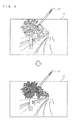
- FIG. 3 is a view showing an example of a screen display which is displayed on the lower LCD 12 and color-converted.
- FIG. 4 is a view showing an example of a hue circle used in the color conversion program.
- FIG. 5 is a view showing an example of a hue range determined as a conversion target with respect to a touch position TP and an example of changing saturation (chroma) with respect to the conversion target.
- FIG. 6 is a view showing another example of the screen display which is displayed on the lower LCD 12 and color-converted.
- FIG. 7 is a view showing an example of hue ranges determined as conversion targets with respect to a plurality of touch positions TP1 and TP2 and an example of changing saturation with respect to the conversion targets.
- a real-time image (a taken image) taken by the inner camera 23 or the outer camera 25 is displayed on the lower LCD 12 of the game apparatus 1.
- the taken image is a chromatic image, but a display image obtained by changing the taken image into a monochrome image (namely, an achromatic image obtained by changing saturation of all pixels of the taken image into 0) is displayed once on the lower LCD 12 (an upper diagram in FIG. 3 ). Then, saturation of the display image is changed in accordance with a hue of a pixel of the taken image corresponding to a touch position at which a touch operation is performed with respect to the touch panel 13, and a resultant image is displayed on the lower LCD 12 (a lower diagram in FIG. 3 ).
- the upper diagram in FIG. 3 shows an example in which a monochrome image obtained by changing saturation of each pixel of the taken image, which is the chromatic image, to 0 is displayed on the lower LCD 12.
- a touch operation at a position on the monochrome image displayed on the lower LCD 12
- color is added to only pixels having hues in the vicinity of a hue which is the same as a hue of the taken image corresponding to the position, and an resultant image is displayed on the lower LCD 12.
- the user performs a touch operation at a position at which green is originally expressed in imaging.
- the lower diagram in FIG. 3 shows a state in which a display image obtained by adding originally expressed green to only portions of the monochrome image at which green is originally expressed in imaging (portions of leaves of trees in the lower diagram in FIG. 3 ) in accordance with the touch operation.
- a color e.g. an RGB value
- a hue corresponding to the detected color of the pixel is calculated, and a predetermined range having the hue at a center thereof is set as a color conversion target. Saturation for the hue which is the color conversion target is changed to a value larger than 0.
- pixels having the hue which is the color conversion target is changed from a monochromatic color to a chromatic color, and an image in which color is added naturally such that a color at the position at which the user performs the touch operation is changed to an originally expressed color is displayed on the lower LCD 12.
- FIG. 4 shows an example of using the Munsell hue circle.
- the Munsell hue circle divides into five principal hues (red, yellow, green, blue, purple) and intermediate hues halfway between the adjacent principal colors (yellow-red, green-yellow, blue-green, purple-blue, red-purple), namely, a total of 10 hues, further divides between these hues, and arranges these hues in a circle.
- a predetermined angular range e.g. 50 degrees before and after the hue having the hue at a center thereof in the Munsell hue circle is set as a color conversion target.
- hue dividing intervals are equal to each other.
- a selected hue is either color, it is easy to set a range having the hue at a center thereof.
- another hue circle may be used.
- another color system such as a PCCS (Practical Color Co-ordinate System), an Ostwald color system, an NCS (Natural Color System), an XYZ color system, or the like, may be used.
- PCCS Manufacturing Color Co-ordinate System
- an Ostwald color system such as an Ostwald color system
- NCS Natural Color System
- XYZ color system or the like
- various color systems using at least hue as an attribute for expressing color can be used.
- FIG. 5 shows an example of the color conversion target which is set using the above Munsell hue circle, and an example of changing saturation with respect to the color conversion target.
- a color conversion range is set so as to have a hue "green” at a center thereof and so as to have 50 degrees before and after the hue "green” in the Munsell hue circle (namely, a range of a total of 100 degrees).
- the set color conversion range is divided into a range in which a rate of returning saturation to original saturation (hereinafter, referred to as a saturation reproduction rate) is 100% and a range in which the saturation reproduction rate is changed so as to be gradually decreased from 100% to 0%.
- the saturation reproduction rate is a rate of saturation of a monochromatic display image with respect to saturation of an original image (namely, a chromatic taken image), and saturation which is larger than saturation of the original image is not set.
- a saturation reproduction rate of 100% in color conversion means to change saturation of pixels of the color conversion target which are set to 0 in the monochromatic display image to saturation of the pixels in the original image to display a resultant image.
- Changing saturation at a saturation reproduction rate of 50% in color conversion means to change the saturation of the pixels of the color conversion target to half (50%) of the saturation of the pixels in the original image to display a resultant image.
- a hue corresponding to a touch position TP when a hue corresponding to a touch position TP is "green", a range between 5 degrees before and after the hue in the Munsell hue circle (namely, a range of a total of 10 degrees) is set to a range in which the saturation reproduction rate is 100%. Further, when the hue corresponding to the touch position TP is "green", ranges from 5 to 50 degrees before and after the hue in the hue are set to ranges in which the saturation reproduction rate is changed so as to be gradually decreased from 100% to 0%. In other words, saturation with respect to the range between 5 degrees before and after the detected hue corresponding to the touch position TP is changed at a saturation reproduction rate of 100%, and the saturation reproduction rate is gradually decreased as the hue is distance therefrom. More specifically, as shown in FIG. 5 , from a hue 5 degrees away from the selected hue to a hue 50 degrees away from the selected hue in the Munsell hue circle, the saturation is set so as to be linearly changed at a saturation reproduction rate of 100% to 0%.
- the saturation As described above, by gradually decreasing the saturation, it is possible to express an image such that a color originally obtained in imaging is added naturally to the monochrome image. Further, the user can easily generate an image in which a desired color is added only by performing a touch operation at one position with respect to the display image displayed on the lower LCD 12. Further, the hue which is selected in accordance with the touch operation is set at a center, and the saturation is set so as to be decreased in a phased manner. Thus, noise can be reduced in performing color conversion, and it is possible to convert into an image in which the color at the position at which the touch operation is performed is naturally added.
- An upper diagram in FIG. 6 shows another example in which a monochrome image obtained by changing saturation of each pixel of the taken image, which is the chromatic image, to 0 is displayed on the lower LCD 12. More specifically, in the upper diagram in FIG. 6 , an image of color balls of various colors is taken, and a monochrome image generated from the taken image is displayed on the lower LCD 12. For example, in the upper diagram in FIG. 6 , in the monochrome image displayed on the lower LCD 12, the user performs a touch operation with respect to a color ball whose image is taken originally in green.
- a middle diagram in FIG. 6 shows a state in which a display image obtained by adding originally expressed green only to portions (color balls of green which are indicated by slant line regions in the middle diagram in FIG. 6 ) of the monochrome image whose images are originally taken in green is displayed on the lower LCD 12 in accordance with the touch operation.
- a lower diagram in FIG. 6 in a display image obtained by adding color only to pixels of the monochrome image displayed on the lower LCD 12 which have hues in the vicinity of green which is originally obtained in imaging, the user further performs a touch operation with respect to a color ball whose image is taken originally in blue.
- the lower diagram in FIG. 6 shows a state in which a display image obtained by adding originally expressed blue to portions (color balls of blue which are indicated by filled regions in the lower diagram in FIG. 6 ) whose images are originally taken in blue, in addition to the portions of the monochrome image whose images are taken originally in green, is displayed on the lower LCD 12 in accordance with the touch operation.
- a hue of a pixel of the taken image corresponding to a first touch position TP1 by the user is green.
- a first color conversion range is set so as to have the hue "green” at a center thereof similarly as in FIG. 5 and so as to have 50 degrees before and after the hue "green” in the Munsell hue circle.
- a saturation reproduction rate for the first color conversion range is the same as that in the example described with reference to FIG. 5 , and thus the detail description thereof will be omitted.
- a hue of a pixel of the taken image corresponding to a second touch position TP2 of the user is blue.
- a second color conversion range is set so as to have a hue "blue” at a center thereof similarly as the first color conversion range and so as to have 50 degrees before and after the hue "blue” in the Munsell hue circle.
- the set second color conversion range is divided into a region in which saturation is changed at a saturation reproduction rate of 100% and a region in which saturation is changed so as to be gradually decreased at a saturation reproduction rate changed of 100% to 0%.
- a range between 5 degrees before and after the hue in the Munsell hue circle are set to a range in which saturation is changed at a saturation reproduction rate of 100%, and ranges from 5 to 50 degrees before and after the hue are set to ranges in which saturation is changed so as to be gradually decreased at a saturation reproduction rate of 100% to 0%.
- the hue "red” in the Munsell hue circle is set at a circle angular position of 0 degree
- the hue "green” is set at a circle angular position of 144 degrees
- the hue "blue” is set at a circle angular position of 216 degrees.
- the first color conversion range set for the hue "green” partially overlaps with the second color conversion range set for the hue "blue”.
- a higher saturation reproduction rate is selected among saturation reproduction rates set for the color conversion ranges (see FIG. 7 ).
- saturation reproduction rates are smoothly connected in a range where the plurality of color conversion ranges overlap with each other, thereby enabling color conversion processing to be performed without an uncomfortable feeling.
- FIG. 8 is a view showing an example of various data stored in the main memory 32 in accordance with execution of the color conversion program.
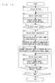
- FIG. 9 is a flow chart of the color conversion processing executed by the game apparatus 1 executing the color conversion program.
- a program for executing these processing is included in a program stored in the memory card 28 or the memory card 29, and read out from the memory card 28 or the memory card 29 via the memory card I/F 36 into the main memory 32 to be executed by the CPU 31 when the power of the game apparatus 1 is turned on.
- programs read out from the memory card 28 and the memory card 29, and temporal data generated in the color conversion processing are stored in the main memory 32.
- touch coordinate data Da, taken image data Db, taken image RGB data Dc, touch position RGB data Dd, conversion target hue data De, conversion table data Df, display image data Dg, and the like are stored.
- touch coordinate data Da data of touch coordinates indicative of a touch position TP in a screen coordinate system at which a player touches the touch panel 13 is stored.
- touch coordinates are obtained at intervals of a time unit at which the game apparatus 1 performs a game process (e.g. every 1/60 sec.), and accordingly, data indicative of the touch coordinates is stored in the touch coordinate data Da for updating the touch coordinate data Da.
- the taken image data Db data of a real-time image taken by the inner camera 23 or the outer camera 25 is stored.
- an image is taken by the inner camera 23 or the outer camera 25 at intervals of a predetermined time unit (e.g. every 1/60 sec.), and accordingly, data of the taken image is stored in the taken image data Db for updating the taken image data Db.
- a predetermined time unit e.g. every 1/60 sec.
- data of the taken image is stored in the taken image data Db for updating the taken image data Db.
- the taken image RGB data Dc data indicative of an RGB value of each pixel of the image taken by the inner camera 23 or the outer camera 25 is stored.
- the touch position RGB data Dd data indicative of an RGB data of a pixel of the taken image corresponding to a touch position TP is stored. For example, in accordance with a touch position TP at which a touch-on is performed with respect to the touch panel 13, a pointed position which is designated in a display image displayed on the lower LCD 12 (e.g. a position to which the touch position TP is perspectively projected in the display image) is calculated. Then, a pixel corresponding to the calculated pointed position is extracted, and data indicative of an RGB value of the pixel is stored in the touch position RGB data Dd.
- the conversion target hue data De data indicative of the aforementioned color conversion range is stored. For example, a hue corresponding to the RGB value at the touch position TP which is stored in the touch position RGB data Dd is calculated, and data indicative of a predetermined range (a color conversion range) having the hue at a center thereof is stored in the conversion target hue data De.
- the conversion table data Df data indicative of a conversion table used in converting an image taken by the inner camera 23 or the outer camera 25 into a display image to be displayed on the lower LCD 12 is stored.
- data indicative of a color which corresponds to an RGB value and is to be displayed on the lower LCD 12 is stored. More specifically, a hue, brightness (value), and saturation which correspond to each RGB value are described in the conversion table, and an RGB value of each pixel of the taken image is converted into a color described in the conversion table to generate a display image.
- the display image data Dg data indicative of the display image obtained by conversion with the conversion table is stored.
- a boot program (not shown) is executed by the CPU 31 to load the color conversion program stored in the memory card 28 or 29 into the main memory 32.
- steps shown in FIG. 9 (abbreviated as "S" in FIG. 9 ) are executed.
- a processing loop of steps 51 to 58 shown in FIG. 9 is executed every a predetermined time period (e.g. every 1/60 sec.).
- the CPU 31 performs initial setting for the color conversion processing (a step 50), and advances the processing to the next step. For example, as the initial setting executed at the step 50, the CPU 31 initializes each of parameters stored in the main memory 32 to a predetermined value.
- the conversion table stored in the conversion table data Df is initialized to a table in which a color for each RGB value is converted into a color having a saturation value of 0 (namely, an achromatic color).
- the CPU 31 obtains data of a real-time image taken by the inner camera 23 or the outer camera 25 (the step 51), and advances the processing to the next step.
- a chromatic image is taken in real time by one of the inner camera 23 and the outer camera 25, and the taken image data Db and the taken image RGB data Dc are updated with data indicative of an RGB value of each pixel of the taken image, and the like.
- the CPU 31 converts a color of each pixel of the taken image with the conversion table to display a resultant image on the lower LCD 12 (the step 52), and advances the processing to the next step.
- the CPU 31 converts the RGB value of each pixel of the taken image which is stored in the taken image RGB data Dc into a color stored in the conversion table data Df with the conversion table to generate a display image, and updates the display image data Dg with the display image. Then, the CPU 31 displays the display image stored in the display image data Dg on the lower LCD 12.
- the conversion table stored in the conversion table data Df is in an initial state (namely, in a set state in which a color for each RGB value is converted into a color having a saturation value of 0, the chromatic taken image is converted into an achromatic (monochrome) display image, and displayed on the lower LCD 12.
- the CPU 31 determines whether or not a touch input has been performed with respect to the touch panel 13 (the step 53). When the touch input has been performed, the CPU 31 advances the processing to the next step 54. On the other hand, when the touch input has not been performed, the CPU 31 advances the processing to the step 58.
- the CPU 31 obtains touch coordinates indicative of a touch position TP in the screen coordinate system at which the touch panel 13 has been touched, and advances the processing to the next step. For example, the CPU 31 updates the touch coordinates stored in the touch coordinate data Da with the obtained touch coordinates.
- the CPU 31 obtains an RGB value of the taken image corresponding to the touch position TP obtained at the step 54 (the step 55), and advances the processing to the next step. For example, the CPU 31 calculates a pointed position which is designated in the display image displayed on the lower LCD 12 (e.g. a position to which the touch position TP is perspectively projected in the display image) in accordance with the touch position TP. Then, the CPU 31 refers to the taken image RGB data Dc, extracts a pixel of the taken image corresponding to the calculated pointed position, and updates the touch position RGB data Dd with data indicative of the RGB value of the pixel.
- a pointed position which is designated in the display image displayed on the lower LCD 12 (e.g. a position to which the touch position TP is perspectively projected in the display image) in accordance with the touch position TP.
- the CPU 31 refers to the taken image RGB data Dc, extracts a pixel of the taken image corresponding to the calculated pointed position, and updates the touch position RGB data Dd with data indicative of
- the CPU 31 calculates a conversion target range based on the RGB value obtained at the step 55 (the step 56), and advances the processing to the next step. For example, the CPU 31 converts the RGB value obtained at the step 55 into a hue, and calculates a predetermined circle angular range having the hue at a center thereof in the Munsell hue circle (see FIG. 4 ) as a conversion target range (see FIGS. 5 and 7 ). Then, the CPU 31 updates the conversion target hue data De with the calculated conversion target range.
- the CPU 31 changes saturation in the conversion table with respect to the conversion target range calculated at the step 56 (the step 57), and advances the processing to the next step. For example, the CPU 31 sets a range between 5 degrees before and after the hue at the center of the conversion target range to a range in which saturation is changed at a saturation reproduction rate of 100%, and sets ranges from 5 to 50 degrees before and after the hue to ranges in which saturation is changed so as to be gradually decreased at a saturation reproduction rate of 100% to 0% (see FIG. 5 ).
- the CPU 31 sets a range in the conversion table in which hues within the conversion target range are described as a target whose saturation is to be changed, and changes saturation of colors described in the conversion table at the saturation reproduction rates according to the described hues to update the conversion table data Df.
- the saturation is changed and written in the conversion table for each of hues which newly become change targets.
- a region in the conversion table in which saturation is set to a value other than 0 is increased every time the processing is performed.
- the CPU 31 selects a higher saturation reproduction rate, and changes the saturation for the hue at the selected saturation reproduction rate (see FIG. 7 ).
- the conversion table is updated with a conversion table in which saturation for the predetermined range having at the center thereof the hue corresponding to the position at which the touch operation is performed is changed to saturation larger than 0 to have a chromatic color. Then, by executing the step 52 after the update of the conversion table, the taken image in which hues within the predetermined range having at the center thereof the hue corresponding to the position at which the touch operation is performed are added is displayed on the lower LCD 12.
- the CPU 31 determines whether or not to terminate the color conversion processing (the step 58).
- a condition for terminating the color conversion processing includes, for example, satisfaction of conditions to terminate the color conversion processing, an operation performed by the user for terminating the color conversion processing, and the like.
- the CPU 31 returns to the step 51, and repeats the processing.
- terminating the color conversion processing the CPU 31 terminates the processing by the flow chart.
- the game apparatus 1 is capable of performing color conversion desired by the user only by the user once touching an image displayed on the lower LCD 12 at a position at which a color desired by the user is originally expressed. Further, when a color conversion target is limited only to a hue of a pixel overlapping with a position at which a touch operation is performed and color conversion is performed, it is considered that a significantly limited region (in an extreme case, only a pixel overlapping with a touch position) is color-converted in a display image, and color conversion desired by the user cannot be performed.
- the game apparatus 1 sets not only a hue according to the touch operation but also hues within a predetermined range having the hue at a center thereof as a range of a color conversion target.
- hues slightly away from a hue of a pixel overlapping with the touch position can be color conversion targets, thereby enabling color conversion desired by the user to be performed.
- saturation is set so as to be decreased from 100% to 0% at a linear rate.
- saturation may be decreased from 100% to 0% in another manner.
- the saturation may be set so as to be decreased from 100% to 0% at a curved rate using a quadratic function curve, a cubic function curve, a sine curve, a cosine curve, a spline interpolation, or the like.
- the saturation reproduction rates may be combined in another manner.
- the saturation reproduction rates in the overlapping range may be smoothly connected in a curvedmanner.
- the saturation reproduction rates are connected so as to vary in a curved manner such that a center of the overlapping range becomes minimum to combine the saturation reproduction rates.
- the saturation reproduction rates set for a plurality of color conversion ranges are complemented in a curvedmanner to be combined, the saturation reproduction rates in the overlapping range of the plurality of color conversion ranges are smoothly connected, thereby enabling color conversion processing to be performed without an uncomfortable feeling.
- the RGB value corresponding to the touch position TP is obtained using the pixel of the taken image corresponding to the pointed position.
- the RGB value corresponding to the touch position TP may be obtained using a plurality of pixels of the taken image in the vicinity of the pointed position. For example, in accordance with a touch position TP at which the user performs a touch operation with respect to the touch panel 13, a pointed position which is designated in a display image displayed on the lower LCD 12 (e.g. a position to which the touch position TP is perspectively projected in the display image) is calculated.
- the taken image RGB data Dc pixels of the taken image within a predetermined distance from the calculated pointed position are extracted, and a representative RGB value for these pixels is calculated using data indicative of RGB values of these pixels.
- the representative RGB value is an RGB value indicative of a main color in the pixels of the taken image within the predetermined distance from the pointed position.
- an RGB value which is set most frequently is set as the representative RGB value.
- an average of the RGB values set for the pixels of the taken image within the predetermined distance from the pointed position is set as the representative RGB value.
- the hues within the predetermined range having at a center thereof the hue according to the touch operation performed by the user with respect to the image displayed on the lower LCD 12 are set as a range of the color conversion target.
- Color conversion processing of increasing saturation is performed for pixels having the hues within the range.
- other color conversion processing may be performed for the pixels.
- color conversion processing of decreasing saturation is performed for the pixels having the hues within the range of the color conversion target.
- a real-time chromatic image taken by the inner camera 23 or the outer camera 25 (typically, a display image which is a taken image without change) is displayed on the lower LCD 12, and hues within a predetermined range having at a center thereof a hue according to a touch operation performed by the user with respect the chromatic image are set as a range of the color conversion target.
- color conversion processing of decreasing saturation is performed for pixels having the hues within the range, whereby the taken image in which only a color selected by the user is changed to a monochrome color is displayed on the lower LCD 12.
- color conversion processing of increasing brightness is performed for the pixels having the hues within the range of the color conversion target.
- a display image obtained by changing brightness of all pixels of a real-time image taken by the inner camera 23 or the outer camera 25 to 0 namely, a black image whose surface is filled with black
- a hue of the taken image according to a touch operation performed by the user with respect to the black image displayed on the lower LCD 12 is extracted, and hues within a predetermined range having the hue at a center thereof are set as a range of the color conversion target.
- the color conversion processing of increasing brightness is performed for pixels having the hues within the range, whereby the taken image in which only a color selected by the user appears on the black image is displayed on the lower LCD 12.
- color conversion processing of decreasing brightness is performed for the pixels having the hues within the range of the color conversion target.
- a real-time chromatic image taken by the inner camera 23 or the outer camera 25 (typically, a display image which is a taken image without change) is displayed on the lower LCD 12, and hues within a predetermined range having at a center thereof a hue according to a touch operation performed by the user with respect the chromatic image are set as a range of the color conversion target.
- the color conversion processing of decreasing brightness is performed for the pixels having the hue within the range, whereby the taken image in which only a color selected by the user is changed to a dark color is displayed on the lower LCD 12.
- color conversion processing of sequentially changing hue is performed for the pixels having the hues within the range of the color conversion target.
- a real-time chromatic image taken by the inner camera 23 or the outer camera 25 (typically, a display image which is a taken image without change) is displayed on the lower LCD 12, and hues within a predetermined range having at a center thereof a hue according to a touch operation performed by the user with respect the chromatic image are set as a range of the color conversion target. Then, for pixels having the hues within the range, the hues are changed sequentially as time passes.
- the color conversion processing of sequentially changing hue the taken image in which only a color selected by the user is gradually changed is displayed on the lower LCD 12.
- the color conversion processing in the fourth example can be performed by the game apparatus 1 executing color conversion processing of a flow chart shown in FIG. 10 .
- the CPU 31 executes the same processing as those at the above steps 50 to 56 to calculate a hue range of the conversion target.
- the CPU 31 circularly changes hues in the conversion table with respect to the conversion target range calculated at the step 66 (a step 67), and advances the processing to the next step 68.
- the CPU 31 sequentially changes the hues within the conversion target range in order of a forward direction of hues arranged in the Munsell hue circle (namely, in order ofred,yellow-red,yellow,green-yellow,green,blue-green, blue, purple-blue, purple, red-purple, and red) or in order of a reverse direction.
- the CPU 31 executes the same processing as those at the above steps 51 and 52.
- the CPU 31 determines whether or not a predetermined constant time period has elapsed (a step 70). When the constant time period has elapsed, the CPU 31 returns to the step 67, and repeats the processing. On the other hand, when the constant time period has not elapsed, the CPU 31 determines whether to terminate the color conversion processing similarly at the step 58. When not terminating the color conversion processing, the CPU 31 returns to the step 58, and repeats the processing. When terminating the color conversion processing, the CPU 31 terminates the processing by the flow chart.
- color conversion processing of changing hue in accordance with a color conversion relational expression is performed for the pixels having the hues within the range of the color conversion target.
- a real-time chromatic image taken by the inner camera 23 or the outer camera 25 (typically, a display image which is a taken image without change) is displayed on the lower LCD 12, and hues within a predetermined range having at a center thereof a hue in accordance with a touch operation performed by the user with respect the chromatic image are set as a range of the color conversion target.
- the hues are changed to predetermined hues (e.g. changed to hues having diagonal relationships in the Munsell hue circle, or hues away therefrom by a predetermined circle angle in the Munsell hue circle).
- the set color conversion target range is set to have a range in which hues before conversion are changed to predetermined hues (referred to as conversion target hues) and a range in which hues before conversion are changed so as to be gradually increased to be close to the conversion target hues.
- conversion target hues a range in which hues before conversion are changed to predetermined hues
- hues before conversion are changed so as to be gradually increased to be close to the conversion target hues.
- FIG. 11 represents an example of a color conversion relational expression in which a hue before color conversion (a real-time chromatic image taken by the inner camera 23 or the outer camera 25) is indicated as a hue angle X in the Munsell hue circle along a horizontal axis, and a hue after color conversion is indicated as a hue angle Y in the Munsell hue circle along a vertical axis.
- a graph indicating a relational expression between the hue angle Y and the hue angle X is represented using a heavy line.
- a hue of a pixel of a taken image which corresponds to a touch position TP by the user is green, and the green is color-converted into purple.
- a hue angle X of the hue (e.g. the hue "green") of the pixel of the taken image which corresponds to the touch position TP is set to X0
- a hue angle Y of the above conversion target hue e.g. the hue "purple”
- a range having a hue angle of ⁇ Xs + ⁇ Xg before and after the hue "green” (the hue angle X0) as a center thereof in the Munsell hue circle i.e. a range having a hue angle of 2 ⁇ Xs + 2 ⁇ Xg) is set as the range of the color conversion target.
- a hue angle which is smaller than the hue angle X0 by a hue angle of ⁇ Xs is Xls
- a hue angle which is larger than the hue angle X0 by the hue angle of ⁇ Xs is Xrs.
- all hues which belong to a range having a hue angle of ⁇ Xs before and after the hue "green" (the hue angle X0) as a center thereof in the Munsell hue circle namely, all hues of hue angles X which belong to a range from the hue angle Xls to the hue angle Xrs, are converted into the conversion target hue (the hue angle Y0).
- a hue angle which is smaller than the hue angle Xls by a hue angle of ⁇ Xg is Xle.
- dif 360 ⁇ ° - Y ⁇ 0 - X .
- hue angle which is larger than the hue angle Xrs by the hue angle of ⁇ Xg is Xre.
- the hue angles X are converted into the hue angles Y of which hues are maintained without change.
- the hue angle X and the hue angle Y are set in polar coordinates.
- the color conversion processing operation in the fifth example is smilar to the above operation based on the flow chart in FIG. 9 , but instead of "changing saturation in the conversion table" at the step 57, "hue in the conversion table is changed" in accordance with the above color conversion relational expression.
- a hue before color conversion is color-converted so as to be gradually increased to be close to the conversion target hue while hues away within a predetermined hue angle from the hue of the pixel corresponding to the touch position TP are color-converted
- a color which is originally obtained in imaging can be expressed so as to be naturally changed to a predetermined color.
- the user can generate an image in which a desired color is converted into another color only by performing a touch operation at one point with respect to the display image displayed on the lower LCD 12.
- hues which belong to hue angles adjacent to the center are color-converted so as to be gradually close to the conversion target hue, other color conversion may be performed.
- all hues which belong to hue angles within the range of the color conversion target may be cooler-converted into the above conversion target hue.
- the above description is an example in the case of only once performing color conversion in accordance with a touch operation by the user with respect to a displayed image from a state where an original image (a real-time chromatic image taken by the inner camera 23 or the outer camera 25) is displayed, color conversion may be repeatedly performed after the color conversion is performed.
- the conversion target hue is set as the hue angle Y which is a fixed value
- the conversion target hue may be a value which is changed in accordance with a touch operation by the user. The following will describe a case where the conversion target hue is changed in accordance with a touch operation by the user and color conversion is repeatedly performed.
- a hue angle X of pixels of a taken image is changed to a hue angle f(X) by color conversion processing performed last time, and a resultant image is displayed on the screen. It is assumed that in this state, the user performs a touch operation again to further perform color conversion, the hue angle X of the pixels of the taken image is changed to a hue angle f' (X), and a resultant image is displayed on the screen.
- a range having a hue angle of ⁇ Xs + ⁇ Xg before and after the hue angle X0 as a center thereof in the Munsell hue circle i.e. a range having a hue angle of 2 ⁇ Xs + 2 ⁇ Xg) is set as the range of the color conversion target this time.
- the hue of the pixel corresponding to the touch position TP which is displayed on the screen is the hue angle Y1.
- the conversion target hue of this time is the hue angle Y1.
- hue angle X of the hue of the pixel of the taken image which corresponds to the touch position TP is changed to the hue angle f (X) by the color conversion processing performed last time
- Y1 is a hue angle of the conversion target hue which is newly set in the color conversion processing of this time.
- hue angle X of the hue of the pixel of the taken image which corresponds to the touch position TP is changed to the hue angle f(X) by the color conversion processing performed last time
- a hue within a second color conversion range having at a center thereof a hue of the other pixel may be converted into a second hue.
- a different color conversion range is set in accordance with the touch position TP, and another conversion target hue is set in accordance with the color conversion range.
- a hue is changed with a different hue being set as a conversion target for each touch operation.
- a conversion target hue which is set with respect to the first color conversion range may be the same as a conversion target hue which is set with respect to the second color conversion range. In this case, even when the user performs a touch operation at positions of different hues with respect to the above real-time chromatic image, the hues which the touch operation is performed with respect to are color-converted into the same hue.
- a hue angle may be set by another method.
- a hue angle which is set with respect to each color conversion range a hue angle which is changed more largely (namely, a hue angle which is changed more largely from an original image) is selected.
- hue angles after conversion are smoothly connected in accordance with largeness of the overlapping range between the first color conversion range and the second color conversion range. As described above, even when the hue angles in the overlapping range between the first color conversion range and the second color conversion range are combined, it is possible to perform color conversion processing without an uncomfortable feeling by smoothly connecting the hue angles in the overlapping range.
- the color conversion processing of changing one of color attributes is performed for the pixels having the hues within the range of the color conversion target.
- the color conversion processing may be performed for pixels having hues outside the range.
- processing which is different from the color conversion processing performed for the pixels having the hues within the range e.g. a color attribute to be changed is different, or a color attribute to be changed is the same but a direction of change is different
- a color attribute to be changed is different, or a color attribute to be changed is the same but a direction of change is different
- color conversion processing of increasing saturation or brightness within the range when the color conversion processing of increasing saturation or brightness within the range is performed, color conversion processing of decreasing saturation or brightness outside the range is performed.
- color conversion processing of changing the hues within the range is performed in order of the forward direction in a color system
- color conversion processing of changing the hues outside the range is performed in order of the reverse direction in the color system.
- an RGB value of each pixel of a taken image is converted into a hue using the conversion table to generate a display image, and color conversion is performed such that at least one of saturation, brightness, and hue which are described in the conversion table is changed.
- color conversion may be performed by another method.
- image data may be changed by directly changing at least one of saturation, brightness, and hue of an image being displayed (e. g. a taken image) without changing the conversion table with respect to a calculated conversion target range.
- a real-time image (a taken image) taken by the inner camera 23 or the outer camera 25 is used as an image to be color-converted.
- another image may be the image to be color-converted.
- the game apparatus 1 is capable of performing a photographing instruction by the user pressing a predetermined button, and an image taken in accordance with the photographing instruction may be an image to be treated with the color conversion processing of the present invention.
- the user can perform a instruction to perform photographing using the inner camera 23 or the outer camera 25 by pressing the operation button 14G or the operation button 14H of the game apparatus 1. Then, by the photographing processing, an image taken by the inner camera 23 or the outer camera 25 can be stored in the stored data memory 34 or the memory card 28. If, at the step 51, the CPU 31 obtains the image obtained by such photographing processing, the image stored once in the stored data memory 34 or the memory card 28 can be used as an image to be treated with the color conversion processing of the present invention.
- the image stored in the stored data memory 34 or the memory card 28 is not limited to an image taken by the game apparatus 1, and even if the image stored in the stored data memory 34 or the memory card 28 is another image (an image taken by another apparatus, an image obtained by communication with another apparatus, an image pre-installed in the stored data memory 34 or the memory card 28, and the like), the image may be used as an object to be treated with the color conversion processing of the present invention. Further, an image pre-installed in the memory card 29 (e.g. a game image displayed by a game program stored in the memory card 29) may be used as the object to be treated with the color conversion processing of the present invention. In these cases, it should be understood that even if the game apparatus 1 does not have an imaging function, such as the inner camera 23, the outer camera 25, and the like, the present invention can be realized.
- an imaging function such as the inner camera 23, the outer camera 25, and the like
- the game apparatus 1 takes and stores a still image using the inner camera 23 and the outer camera 25 has been described as an example.
- the game apparatus 1 may take and store a moving image using the inner camera 23 or the outer camera 25.
- the moving image taken and stored using the inner camera 23 or the outer camera 25 is used as an image to be treated with the color conversion processing of the present invention.
- the game apparatus 1 may change an LCD for displaying a real-time image taken by the inner camera 23 or the outer camera 25, for example, between the upper LCD 22 and the lower LCD 12 in accordance with a change instruction from the user, or may cause a real-time image taken by the inner camera 23 or the outer camera 25 to be displayed on both LCDs.
- a taken image namely, a display image which has been treated with the color conversion processing of the present invention, is also displayed on the upper LCD 22.
- the case where the lower LCD 12 and the upper LCD 22 physically separated from each other are arranged one above the other has been described as an example of a LCD display section having two screens.
- a configuration of a display section having two screens may be another configuration.
- the lower LCD 12 and the upper LCD 22 may be arranged on a main surface of the lower housing 11 laterally side by side.
- a vertically long LCD having the same width as that of the lower LCD 12 and a vertical length which is twice as large as that of the lower LCD 12 (namely, an LCD which is physically one unit and has a display size with a vertical length equal to a sum of vertical lengths of two screens may be provided in the main surface of the lower housing 11, and the above two images (namely, a display image obtained by changing a taken image to a monochrome image, and an image showing an operation explanation screen) may be displayed one above the other (displayed so as to be adjacent to each other without a boundary portion between above and below).
- a horizontally long LCD having the same vertical length as that of the lower LCD 12 and a width which is twice as large as that of the lower LCD 12 may be provided in the main surface of the lower housing 11, and the two game images may be displayed laterally side by side (displayed so as to be adjacent to each other without a boundary portion between left and right).
- a physically one screen may be divided into two and used to display two images.
- the touch panel 13 may be provided on an entirety of the screen.
- the game apparatus 1 is provided integrally with the touch panel 13.
- the touch panel 13 may be provided on an upper surface of the upper LCD 22, and the display image displayed on the lower LCD 12 may be displayed on the upper LCD 22.
- the two display screens are provided in the above embodiment, only one display screen may be provided.
- the upper LCD 22 may not be provided, only the lower LCD 12 may be provided as a display screen, and the touch panel 13 may be provided on the lower LCD 12.
- the lower LCD 12 may not be provided, the touch panel 13 may be provided on the upper surface of the upper LCD 22, and the display image displayed on the lower LCD 12 may be displayed on the upper LCD 22.
- the touch panel 13 is used as input means of the game apparatus 1 for realizing an coordinate input.
- the touch panel 13 is used as input means of the game apparatus 1 for realizing an coordinate input.
- the pointing device is an input device for designating an input position or coordinates on a screen, and, for example, a mouse, a trackpad, a trackball, or the like is used as the input device.
- position information in a screen coordinate system calculated from an output value outputted from the input device is used, the present invention can be realized similarly.
- the present invention can be realized.
- existence/nonexistence of or change in another input from the input means which is different from the input of the position information is used.
- a determination as to whether or not an operation button provided in the input means is pressed e. g. right click or left click of the mouse is used instead of the determination of the touch-on or the touch-off.
- a pointing device in another form is considered.
- a camera fixed to a housing of the game controller can be used as the pointing device.
- an image taken by the camera is changed.
- coordinates at which the housing is pointed with respect to a display image can be calculated.
- the present invention can be realized.
- existence/nonexistence of or change in another input from the game controller which is different from the coordinate input is used.
- a determination as to whether or not an operation button provided in the game controller is pressed e.g. a touch-on is performed when an A button is pressed
- the game controller includes two housings.
- a camera is provided in one of the two housings, and a detection section, such as an acceleration sensor for outputting a signal in accordance with movement of the other housing, and the like, is fixed to the other housing.
- a determination in accordance with the movement of the other housing e.g. a touch-on is performed when the housing is inclined in a predetermined direction
- voice input means such as a microphone or the like is provided in the housing of the game controller. In this case, a determination to switch between a touch-on and a touch-off when the player produces a predetermined voice is used instead.
- the present invention may be realized by an information processing unit, such as a common personal computer and the like, executing the color conversion processing program of the present invention.
- the shape of the above game apparatus 1, and the shapes, numbers, and installed positions of the operation buttons 14 and the touch panel 13 provided therein are merely an example, and the present invention can be realized with other shapes, numbers and installed positions.
- the set values and the determination values which are used in the above color conversion processing are merely an example, and the present invention can be realized with other values.
- the color conversion apparatus, the imaging apparatus, the storage medium storing the color conversion program, and the storage medium storing the imaging program according to the present invention are useful as apparatuses which are capable of performing color conversion desired by the user with respect to a displayed image in accordance with an easy operation and perform color conversion of various images such as taken images, and the like, and as programs executed by these apparatuses, and the like.
Landscapes
- Engineering & Computer Science (AREA)
- Multimedia (AREA)
- Signal Processing (AREA)
- Image Processing (AREA)
- Processing Or Creating Images (AREA)
- Facsimile Image Signal Circuits (AREA)
- Color Image Communication Systems (AREA)
- Processing Of Color Television Signals (AREA)
Applications Claiming Priority (2)
| Application Number | Priority Date | Filing Date | Title |
|---|---|---|---|
| JP2008120380 | 2008-05-02 | ||
| JP2008161222 | 2008-06-20 |
Publications (3)
| Publication Number | Publication Date |
|---|---|
| EP2114065A2 true EP2114065A2 (de) | 2009-11-04 |
| EP2114065A3 EP2114065A3 (de) | 2011-11-16 |
| EP2114065B1 EP2114065B1 (de) | 2017-08-23 |
Family
ID=39674856
Family Applications (1)
| Application Number | Title | Priority Date | Filing Date |
|---|---|---|---|
| EP08011916.7A Active EP2114065B1 (de) | 2008-05-02 | 2008-07-02 | Farbumwandlungsvorrichtung, Bildgebungsvorrichtung, Speichermedium, das das Farbumwandlungsprogramm speichert und Speichermedium, das das Bildgebungsprogramm speichert |
Country Status (2)
| Country | Link |
|---|---|
| EP (1) | EP2114065B1 (de) |
| JP (1) | JP4282744B1 (de) |
Cited By (1)
| Publication number | Priority date | Publication date | Assignee | Title |
|---|---|---|---|---|
| WO2023125160A1 (zh) * | 2021-12-29 | 2023-07-06 | 维沃移动通信有限公司 | 图像处理方法、装置、电子设备及可读存储介质 |
Families Citing this family (4)
| Publication number | Priority date | Publication date | Assignee | Title |
|---|---|---|---|---|
| JP2011062921A (ja) * | 2009-09-17 | 2011-03-31 | Fuji Xerox Co Ltd | 画像形成装置およびプログラム |
| JP6345612B2 (ja) * | 2015-02-06 | 2018-06-20 | 株式会社ソニー・インタラクティブエンタテインメント | 撮像装置、情報処理システム、マット、および画像生成方法 |
| JP6698277B2 (ja) * | 2015-03-26 | 2020-05-27 | 株式会社バンダイナムコエンターテインメント | プログラム及びゲームシステム |
| JP6922446B2 (ja) * | 2017-06-06 | 2021-08-18 | セイコーエプソン株式会社 | プロファイル調整方法 |
Citations (1)
| Publication number | Priority date | Publication date | Assignee | Title |
|---|---|---|---|---|
| JPH08293995A (ja) | 1995-04-24 | 1996-11-05 | Canon Inc | 画像処理装置及び方法 |
Family Cites Families (3)
| Publication number | Priority date | Publication date | Assignee | Title |
|---|---|---|---|---|
| JP4403397B2 (ja) * | 2004-07-21 | 2010-01-27 | ソニー株式会社 | ユーザインタフェース提供装置 |
| JP4684595B2 (ja) * | 2004-08-05 | 2011-05-18 | ソニー株式会社 | 画像表示装置 |
| JP4438741B2 (ja) * | 2005-11-30 | 2010-03-24 | ソニー株式会社 | 色調整装置、印刷装置、画像処理装置、色調整方法、プログラム |
-
2008
- 2008-07-02 EP EP08011916.7A patent/EP2114065B1/de active Active
- 2008-09-26 JP JP2008249017A patent/JP4282744B1/ja active Active
Patent Citations (1)
| Publication number | Priority date | Publication date | Assignee | Title |
|---|---|---|---|---|
| JPH08293995A (ja) | 1995-04-24 | 1996-11-05 | Canon Inc | 画像処理装置及び方法 |
Cited By (1)
| Publication number | Priority date | Publication date | Assignee | Title |
|---|---|---|---|---|
| WO2023125160A1 (zh) * | 2021-12-29 | 2023-07-06 | 维沃移动通信有限公司 | 图像处理方法、装置、电子设备及可读存储介质 |
Also Published As
| Publication number | Publication date |
|---|---|
| EP2114065A3 (de) | 2011-11-16 |
| JP2010028780A (ja) | 2010-02-04 |
| JP4282744B1 (ja) | 2009-06-24 |
| EP2114065B1 (de) | 2017-08-23 |
Similar Documents
| Publication | Publication Date | Title |
|---|---|---|
| US8451287B2 (en) | Color conversion apparatus, imaging apparatus, storage medium storing color conversion program, and storage medium storing imaging program | |
| US8482572B2 (en) | Storage medium having stored thereon color conversion program, and color conversion apparatus | |
| US8723893B2 (en) | Color conversion apparatus, imaging apparatus, storage medium storing color conversion program and storage medium storing imaging program | |
| CN101049008B (zh) | 图像处理设备和图像处理方法 | |
| CN112037123B (zh) | 唇妆特效的显示方法、装置、设备及存储介质 | |
| US7242409B2 (en) | Interpolated color transform for changing color of an application user interface | |
| CN104364732B (zh) | 图像处理设备 | |
| EP2114065B1 (de) | Farbumwandlungsvorrichtung, Bildgebungsvorrichtung, Speichermedium, das das Farbumwandlungsprogramm speichert und Speichermedium, das das Bildgebungsprogramm speichert | |
| CN108200420B (zh) | 图像调节方法、装置、可读存储介质及终端 | |
| CN115330610B (zh) | 图像处理方法、装置、电子设备以及存储介质 | |
| US8643679B2 (en) | Storage medium storing image conversion program and image conversion apparatus | |
| US10325569B2 (en) | Method and apparatus for coding image information for display | |
| SG187168A1 (en) | Image processing apparatus, image processing method, and computer-readable recording medium | |
| CN112634155B (zh) | 图像处理方法、装置、电子设备及存储介质 | |
| JP6243112B2 (ja) | 情報処理装置、情報処理方法、および記録媒体 | |
| CN112969088A (zh) | 投屏控制方法、装置、电子设备和可读存储介质 | |
| US20160343158A1 (en) | Effect control device, effect control method, and program | |
| CN112738606B (zh) | 音频文件的处理方法、装置、终端及存储介质 | |
| JPWO2010058678A1 (ja) | 指定色領域画定回路、検出回路及びそれを用いた画像処理装置 | |
| JP2007140834A (ja) | プログラム、情報記憶媒体、写真印刷装置及び写真印刷方法 | |
| EP3007137A1 (de) | Bildverarbeitungsvorrichtung, bildverarbeitungsverfahren und programm | |
| CN112346686B (zh) | 显示方法、装置以及存储介质 | |
| CN114518828A (zh) | 屏幕色彩调节方法、装置、终端及计算机可读存储介质 | |
| JP2014062959A (ja) | 表示制御装置、表示装置、投影装置、ポインタ装置及びシステム | |
| CN117119317A (zh) | 图像处理方法、装置、电子设备及可读存储介质 |
Legal Events
| Date | Code | Title | Description |
|---|---|---|---|
| PUAI | Public reference made under article 153(3) epc to a published international application that has entered the european phase |
Free format text: ORIGINAL CODE: 0009012 |
|
| AK | Designated contracting states |
Kind code of ref document: A2 Designated state(s): AT BE BG CH CY CZ DE DK EE ES FI FR GB GR HR HU IE IS IT LI LT LU LV MC MT NL NO PL PT RO SE SI SK TR |
|
| AX | Request for extension of the european patent |
Extension state: AL BA MK RS |
|
| PUAL | Search report despatched |
Free format text: ORIGINAL CODE: 0009013 |
|
| AK | Designated contracting states |
Kind code of ref document: A3 Designated state(s): AT BE BG CH CY CZ DE DK EE ES FI FR GB GR HR HU IE IS IT LI LT LU LV MC MT NL NO PL PT RO SE SI SK TR |
|
| AX | Request for extension of the european patent |
Extension state: AL BA MK RS |
|
| RIC1 | Information provided on ipc code assigned before grant |
Ipc: H04N 1/62 20060101AFI20111011BHEP Ipc: H04N 1/40 20060101ALI20111011BHEP |
|
| RAP1 | Party data changed (applicant data changed or rights of an application transferred) |
Owner name: NINTENDO CO., LTD. |
|
| 17P | Request for examination filed |
Effective date: 20120509 |
|
| AKX | Designation fees paid |
Designated state(s): AT BE BG CH CY CZ DE DK EE ES FI FR GB GR HR HU IE IS IT LI LT LU LV MC MT NL NO PL PT RO SE SI SK TR |
|
| 17Q | First examination report despatched |
Effective date: 20140319 |
|
| GRAP | Despatch of communication of intention to grant a patent |
Free format text: ORIGINAL CODE: EPIDOSNIGR1 |
|
| INTG | Intention to grant announced |
Effective date: 20170208 |
|
| GRAS | Grant fee paid |
Free format text: ORIGINAL CODE: EPIDOSNIGR3 |
|
| GRAA | (expected) grant |
Free format text: ORIGINAL CODE: 0009210 |
|
| AK | Designated contracting states |
Kind code of ref document: B1 Designated state(s): AT BE BG CH CY CZ DE DK EE ES FI FR GB GR HR HU IE IS IT LI LT LU LV MC MT NL NO PL PT RO SE SI SK TR |
|
| REG | Reference to a national code |
Ref country code: GB Ref legal event code: FG4D |
|
| REG | Reference to a national code |
Ref country code: CH Ref legal event code: EP |
|
| REG | Reference to a national code |
Ref country code: AT Ref legal event code: REF Ref document number: 922460 Country of ref document: AT Kind code of ref document: T Effective date: 20170915 |
|
| REG | Reference to a national code |
Ref country code: IE Ref legal event code: FG4D |
|
| REG | Reference to a national code |
Ref country code: DE Ref legal event code: R096 Ref document number: 602008051713 Country of ref document: DE |
|
| REG | Reference to a national code |
Ref country code: NL Ref legal event code: MP Effective date: 20170823 |
|
| REG | Reference to a national code |
Ref country code: LT Ref legal event code: MG4D |
|
| REG | Reference to a national code |
Ref country code: AT Ref legal event code: MK05 Ref document number: 922460 Country of ref document: AT Kind code of ref document: T Effective date: 20170823 |
|
| PG25 | Lapsed in a contracting state [announced via postgrant information from national office to epo] |
Ref country code: HR Free format text: LAPSE BECAUSE OF FAILURE TO SUBMIT A TRANSLATION OF THE DESCRIPTION OR TO PAY THE FEE WITHIN THE PRESCRIBED TIME-LIMIT Effective date: 20170823 Ref country code: FI Free format text: LAPSE BECAUSE OF FAILURE TO SUBMIT A TRANSLATION OF THE DESCRIPTION OR TO PAY THE FEE WITHIN THE PRESCRIBED TIME-LIMIT Effective date: 20170823 Ref country code: LT Free format text: LAPSE BECAUSE OF FAILURE TO SUBMIT A TRANSLATION OF THE DESCRIPTION OR TO PAY THE FEE WITHIN THE PRESCRIBED TIME-LIMIT Effective date: 20170823 Ref country code: AT Free format text: LAPSE BECAUSE OF FAILURE TO SUBMIT A TRANSLATION OF THE DESCRIPTION OR TO PAY THE FEE WITHIN THE PRESCRIBED TIME-LIMIT Effective date: 20170823 Ref country code: SE Free format text: LAPSE BECAUSE OF FAILURE TO SUBMIT A TRANSLATION OF THE DESCRIPTION OR TO PAY THE FEE WITHIN THE PRESCRIBED TIME-LIMIT Effective date: 20170823 Ref country code: NO Free format text: LAPSE BECAUSE OF FAILURE TO SUBMIT A TRANSLATION OF THE DESCRIPTION OR TO PAY THE FEE WITHIN THE PRESCRIBED TIME-LIMIT Effective date: 20171123 Ref country code: NL Free format text: LAPSE BECAUSE OF FAILURE TO SUBMIT A TRANSLATION OF THE DESCRIPTION OR TO PAY THE FEE WITHIN THE PRESCRIBED TIME-LIMIT Effective date: 20170823 |
|
| PG25 | Lapsed in a contracting state [announced via postgrant information from national office to epo] |
Ref country code: BG Free format text: LAPSE BECAUSE OF FAILURE TO SUBMIT A TRANSLATION OF THE DESCRIPTION OR TO PAY THE FEE WITHIN THE PRESCRIBED TIME-LIMIT Effective date: 20171123 Ref country code: IS Free format text: LAPSE BECAUSE OF FAILURE TO SUBMIT A TRANSLATION OF THE DESCRIPTION OR TO PAY THE FEE WITHIN THE PRESCRIBED TIME-LIMIT Effective date: 20171223 Ref country code: ES Free format text: LAPSE BECAUSE OF FAILURE TO SUBMIT A TRANSLATION OF THE DESCRIPTION OR TO PAY THE FEE WITHIN THE PRESCRIBED TIME-LIMIT Effective date: 20170823 Ref country code: LV Free format text: LAPSE BECAUSE OF FAILURE TO SUBMIT A TRANSLATION OF THE DESCRIPTION OR TO PAY THE FEE WITHIN THE PRESCRIBED TIME-LIMIT Effective date: 20170823 Ref country code: GR Free format text: LAPSE BECAUSE OF FAILURE TO SUBMIT A TRANSLATION OF THE DESCRIPTION OR TO PAY THE FEE WITHIN THE PRESCRIBED TIME-LIMIT Effective date: 20171124 Ref country code: PL Free format text: LAPSE BECAUSE OF FAILURE TO SUBMIT A TRANSLATION OF THE DESCRIPTION OR TO PAY THE FEE WITHIN THE PRESCRIBED TIME-LIMIT Effective date: 20170823 |
|
| PG25 | Lapsed in a contracting state [announced via postgrant information from national office to epo] |
Ref country code: DK Free format text: LAPSE BECAUSE OF FAILURE TO SUBMIT A TRANSLATION OF THE DESCRIPTION OR TO PAY THE FEE WITHIN THE PRESCRIBED TIME-LIMIT Effective date: 20170823 Ref country code: RO Free format text: LAPSE BECAUSE OF FAILURE TO SUBMIT A TRANSLATION OF THE DESCRIPTION OR TO PAY THE FEE WITHIN THE PRESCRIBED TIME-LIMIT Effective date: 20170823 Ref country code: CZ Free format text: LAPSE BECAUSE OF FAILURE TO SUBMIT A TRANSLATION OF THE DESCRIPTION OR TO PAY THE FEE WITHIN THE PRESCRIBED TIME-LIMIT Effective date: 20170823 |
|
| REG | Reference to a national code |
Ref country code: DE Ref legal event code: R097 Ref document number: 602008051713 Country of ref document: DE |
|
| PG25 | Lapsed in a contracting state [announced via postgrant information from national office to epo] |
Ref country code: IT Free format text: LAPSE BECAUSE OF FAILURE TO SUBMIT A TRANSLATION OF THE DESCRIPTION OR TO PAY THE FEE WITHIN THE PRESCRIBED TIME-LIMIT Effective date: 20170823 Ref country code: SK Free format text: LAPSE BECAUSE OF FAILURE TO SUBMIT A TRANSLATION OF THE DESCRIPTION OR TO PAY THE FEE WITHIN THE PRESCRIBED TIME-LIMIT Effective date: 20170823 Ref country code: EE Free format text: LAPSE BECAUSE OF FAILURE TO SUBMIT A TRANSLATION OF THE DESCRIPTION OR TO PAY THE FEE WITHIN THE PRESCRIBED TIME-LIMIT Effective date: 20170823 |
|
| REG | Reference to a national code |
Ref country code: FR Ref legal event code: PLFP Year of fee payment: 11 |
|
| PLBE | No opposition filed within time limit |
Free format text: ORIGINAL CODE: 0009261 |
|
| STAA | Information on the status of an ep patent application or granted ep patent |
Free format text: STATUS: NO OPPOSITION FILED WITHIN TIME LIMIT |
|
| 26N | No opposition filed |
Effective date: 20180524 |
|
| PG25 | Lapsed in a contracting state [announced via postgrant information from national office to epo] |
Ref country code: SI Free format text: LAPSE BECAUSE OF FAILURE TO SUBMIT A TRANSLATION OF THE DESCRIPTION OR TO PAY THE FEE WITHIN THE PRESCRIBED TIME-LIMIT Effective date: 20170823 |
|
| REG | Reference to a national code |
Ref country code: CH Ref legal event code: PL |
|
| PG25 | Lapsed in a contracting state [announced via postgrant information from national office to epo] |
Ref country code: LU Free format text: LAPSE BECAUSE OF NON-PAYMENT OF DUE FEES Effective date: 20180702 Ref country code: MC Free format text: LAPSE BECAUSE OF FAILURE TO SUBMIT A TRANSLATION OF THE DESCRIPTION OR TO PAY THE FEE WITHIN THE PRESCRIBED TIME-LIMIT Effective date: 20170823 |
|
| REG | Reference to a national code |
Ref country code: BE Ref legal event code: MM Effective date: 20180731 |
|
| REG | Reference to a national code |
Ref country code: IE Ref legal event code: MM4A |
|
| PG25 | Lapsed in a contracting state [announced via postgrant information from national office to epo] |
Ref country code: IE Free format text: LAPSE BECAUSE OF NON-PAYMENT OF DUE FEES Effective date: 20180702 Ref country code: CH Free format text: LAPSE BECAUSE OF NON-PAYMENT OF DUE FEES Effective date: 20180731 Ref country code: LI Free format text: LAPSE BECAUSE OF NON-PAYMENT OF DUE FEES Effective date: 20180731 |
|
| PG25 | Lapsed in a contracting state [announced via postgrant information from national office to epo] |
Ref country code: BE Free format text: LAPSE BECAUSE OF NON-PAYMENT OF DUE FEES Effective date: 20180731 |
|
| PG25 | Lapsed in a contracting state [announced via postgrant information from national office to epo] |
Ref country code: MT Free format text: LAPSE BECAUSE OF NON-PAYMENT OF DUE FEES Effective date: 20180702 |
|
| PG25 | Lapsed in a contracting state [announced via postgrant information from national office to epo] |
Ref country code: TR Free format text: LAPSE BECAUSE OF FAILURE TO SUBMIT A TRANSLATION OF THE DESCRIPTION OR TO PAY THE FEE WITHIN THE PRESCRIBED TIME-LIMIT Effective date: 20170823 |
|
| PG25 | Lapsed in a contracting state [announced via postgrant information from national office to epo] |
Ref country code: PT Free format text: LAPSE BECAUSE OF FAILURE TO SUBMIT A TRANSLATION OF THE DESCRIPTION OR TO PAY THE FEE WITHIN THE PRESCRIBED TIME-LIMIT Effective date: 20170823 Ref country code: HU Free format text: LAPSE BECAUSE OF FAILURE TO SUBMIT A TRANSLATION OF THE DESCRIPTION OR TO PAY THE FEE WITHIN THE PRESCRIBED TIME-LIMIT; INVALID AB INITIO Effective date: 20080702 |
|
| PG25 | Lapsed in a contracting state [announced via postgrant information from national office to epo] |
Ref country code: CY Free format text: LAPSE BECAUSE OF FAILURE TO SUBMIT A TRANSLATION OF THE DESCRIPTION OR TO PAY THE FEE WITHIN THE PRESCRIBED TIME-LIMIT Effective date: 20170823 |
|
| P01 | Opt-out of the competence of the unified patent court (upc) registered |
Effective date: 20230428 |
|
| PGFP | Annual fee paid to national office [announced via postgrant information from national office to epo] |
Ref country code: GB Payment date: 20250529 Year of fee payment: 18 |
|
| PGFP | Annual fee paid to national office [announced via postgrant information from national office to epo] |
Ref country code: FR Payment date: 20250610 Year of fee payment: 18 |
|
| PGFP | Annual fee paid to national office [announced via postgrant information from national office to epo] |
Ref country code: DE Payment date: 20250528 Year of fee payment: 18 |