EP2113775B1 - Ausgleichssimulator mit Übungssequenzerfassung für ein Oszilloskop - Google Patents
Ausgleichssimulator mit Übungssequenzerfassung für ein Oszilloskop Download PDFInfo
- Publication number
- EP2113775B1 EP2113775B1 EP09251155.9A EP09251155A EP2113775B1 EP 2113775 B1 EP2113775 B1 EP 2113775B1 EP 09251155 A EP09251155 A EP 09251155A EP 2113775 B1 EP2113775 B1 EP 2113775B1
- Authority
- EP
- European Patent Office
- Prior art keywords
- training sequence
- digitized waveform
- waveform record
- oscilloscope
- record
- Prior art date
- Legal status (The legal status is an assumption and is not a legal conclusion. Google has not performed a legal analysis and makes no representation as to the accuracy of the status listed.)
- Active
Links
Images


Classifications
-
- H—ELECTRICITY
- H04—ELECTRIC COMMUNICATION TECHNIQUE
- H04L—TRANSMISSION OF DIGITAL INFORMATION, e.g. TELEGRAPHIC COMMUNICATION
- H04L25/00—Baseband systems
- H04L25/02—Details ; arrangements for supplying electrical power along data transmission lines
- H04L25/0202—Channel estimation
- H04L25/0212—Channel estimation of impulse response
- H04L25/0216—Channel estimation of impulse response with estimation of channel length
-
- H—ELECTRICITY
- H04—ELECTRIC COMMUNICATION TECHNIQUE
- H04L—TRANSMISSION OF DIGITAL INFORMATION, e.g. TELEGRAPHIC COMMUNICATION
- H04L25/00—Baseband systems
- H04L25/02—Details ; arrangements for supplying electrical power along data transmission lines
- H04L25/0202—Channel estimation
- H04L25/0224—Channel estimation using sounding signals
- H04L25/0228—Channel estimation using sounding signals with direct estimation from sounding signals
-
- G—PHYSICS
- G01—MEASURING; TESTING
- G01R—MEASURING ELECTRIC VARIABLES; MEASURING MAGNETIC VARIABLES
- G01R13/00—Arrangements for displaying electric variables or waveforms
- G01R13/02—Arrangements for displaying electric variables or waveforms for displaying measured electric variables in digital form
-
- H—ELECTRICITY
- H04—ELECTRIC COMMUNICATION TECHNIQUE
- H04L—TRANSMISSION OF DIGITAL INFORMATION, e.g. TELEGRAPHIC COMMUNICATION
- H04L25/00—Baseband systems
- H04L25/02—Details ; arrangements for supplying electrical power along data transmission lines
- H04L25/03—Shaping networks in transmitter or receiver, e.g. adaptive shaping networks
- H04L25/03006—Arrangements for removing intersymbol interference
- H04L2025/03433—Arrangements for removing intersymbol interference characterised by equaliser structure
- H04L2025/03439—Fixed structures
- H04L2025/03445—Time domain
- H04L2025/03471—Tapped delay lines
-
- H—ELECTRICITY
- H04—ELECTRIC COMMUNICATION TECHNIQUE
- H04L—TRANSMISSION OF DIGITAL INFORMATION, e.g. TELEGRAPHIC COMMUNICATION
- H04L25/00—Baseband systems
- H04L25/02—Details ; arrangements for supplying electrical power along data transmission lines
- H04L25/03—Shaping networks in transmitter or receiver, e.g. adaptive shaping networks
- H04L25/03006—Arrangements for removing intersymbol interference
- H04L2025/03592—Adaptation methods
- H04L2025/03598—Algorithms
- H04L2025/03605—Block algorithms
-
- H—ELECTRICITY
- H04—ELECTRIC COMMUNICATION TECHNIQUE
- H04L—TRANSMISSION OF DIGITAL INFORMATION, e.g. TELEGRAPHIC COMMUNICATION
- H04L25/00—Baseband systems
- H04L25/02—Details ; arrangements for supplying electrical power along data transmission lines
- H04L25/03—Shaping networks in transmitter or receiver, e.g. adaptive shaping networks
- H04L25/03006—Arrangements for removing intersymbol interference
- H04L25/03012—Arrangements for removing intersymbol interference operating in the time domain
- H04L25/03019—Arrangements for removing intersymbol interference operating in the time domain adaptive, i.e. capable of adjustment during data reception
Definitions
- High speed serial data link systems 10 are composed of a transmitter 12, a channel 14 and a receiver 16 as shown in Figure 1 .
- equalization techniques become necessary to maintain system performance in the presence of channel loss, reflection, cross talk, noise and other factors that degrade the system performance.
- the system performance can be measured in various ways including bit error rate, eye opening, and jitter measurements.
- Industry standards start defining measurement based on equalization measurement or simulation, such as methods proposed to SAS-2 6G standard committee.
- One equalization or simulation method is based on knowing a training sequence, and having the averaged sampled analog data pattern waveform to equalize.
- An equalization adaptation algorithm 20 uses both inputs to optimize equalizer taps as depicted in Figure 2 .
- this method doesn't explicitly take into account the signal components that are not correlated to data pattern, such as periodic and random jitter/noise for equalizer tap optimization.
- the real-time oscilloscopes capture signals without aliasing, so all the frequency dependent information is preserved.
- the equalizer taps are optimized in the sense that all the frequency dependent information has been taken into account. For example, when the sinusoidal noise has energy concentrated at different frequencies, the optimized taps will have different values so that the optimal system performance is achieved accordingly to the specific sinusoidal noise distribution.
- Real-time oscilloscopes have the flexibility to capture any waveforms, even when triggers are difficult or impossible to be obtained precisely. Without any trigger, a real-time oscilloscope can take a long record single shot acquisition to record the waveform, and then process the waveform with equalization simulation.
- WO 2005/101652 relates to a method of controlling a feed forward filter of an equalizer.
- US 2003/072363 relates to the adaptive equalization of a digital modulating signal recovered from an amplitude-modulated signal subject to multipath.
- US 2006/176984 relates to header acquisition techniques for locating a header symbol sequence in a data stream.
- an equalization simulator with training sequence detection for use in an oscilloscope generating a digitized waveform record from acquiring samples of an analog waveform signal from a serial data link as set out in claim 1, and a method of equalization simulation using on oscilloscope as set out in claim 5.
- the present invention is an equalization simulator with training sequence detection for use in an oscilloscope generating a digitized waveform record from acquiring samples of an analog waveform signal from a serial data link.
- the equalization simulator has a training sequence detector receiving the digitized waveform record and generating a training sequence, an equalization adapter receiving the digitized waveform record and the training sequence and generating equalizer taps, and an equalizer receiving the equalizer taps and the digitized waveform record and generating an equalized digitized waveform record of the analog waveform signal.
- the training sequence detector has an input signal processor receiving the digitized waveform and producing a processed digitized waveform record having channel effects of the serial data link removed.
- the input signal processor may be a de-embed filter generated using S- or T- Parameters representing channel characteristics of the serial data link.
- the de-embed filter receives the digitized waveform record and generates a de-embedded processed digitized waveform record.
- the input signal processor may also be a detection equalizer receiving the digitized waveform record and generating an equalized processed digitized waveform record. The output of the input signal processor is applied to the sequence detector.
- the equalization adapter has a means for recovering a clock from the digitized waveform record having a clock rate equal to the bit rate of the analog waveform signal and a re-sampler receiving the digitized waveform record and the recovered clock and generating a re-sampled digitized waveform record using the recovered clock signal according the bit rate of the analog waveform signal.
- the equalization adapter also has means for aligning the re-sampled digitized waveform record with the training sequence to generate an training sequence aligned with the re-sampled digitized waveform record, and means for generating equalizer taps using the re-sampled digitized waveform record and the aligned training sequence.
- the method of equalization simulation with a training sequence detector using an oscilloscope starts with acquiring samples of an analog waveform signal for a digitized waveform record using the oscilloscope.
- a training sequence is detected from the digitized waveform record.
- a clock signal is recovered from the digitized waveform record having a clock rate equal to the bit rate of the analog waveform signal and the digitized waveform record is re-sampled according the bit rate of the analog waveform signal using the recovered clock signal.
- De-emphasis is applied at the center of the bits in the re-sampled digitized waveform record and the detected training sequence is aligned with the de-emphasized re-sampled digitized waveform record.
- Equalizer taps are generated using the re-sampled digitized waveform record and the aligned training sequence. The generated equalizer taps are used in an equalizer to equalizing the digitized waveform record.
- the training sequence detecting step includes at least one of the steps of channel de-embedding, pre-equalization, decreasing the bit rate of the analog waveform signal and acquiring samples of the analog waveform signal at the transmitter end of the channel for a digitized waveform record.
- a channel de-embed filter is generated as a function of the channel characteristics, and a de-embedded digitized waveform record is generated by applying the digitized waveform record to the de-embed filter.
- a multi-tap equalizer generates an equalized digitized waveform record using the digitized waveform record as an input.
- the de-embedded or equalized digitized waveform record is an applied to the sequence detector for detecting the training sequence.
- the training sequence detecting step may include the steps of decreasing the bit rate of the analog waveform signal and acquiring samples of the decreased bit rate analog waveform signal using the oscilloscope for detecting the training sequence.
- the bit rate of the analog waveform signal is increased and samples of the increased bit rate analog waveform signal are acquired using the oscilloscope to generate another digitized waveform record for recovering the clock signal and re-sampling the other digitized waveform record.
- the training sequence detecting step may include the steps of connecting a measurement probe at a transmitter end of a channel and acquiring samples of the analog waveform signal at the transmitter end of the channel using the oscilloscope for detecting the training sequence.
- the measurement probe is connected at a receiver end of the channel, and samples are acquired of the analog waveform signal at the receiver end of the channel using the oscilloscope to generate another digitized waveform record for recovering the clock signal and re-sampling the other digitized waveform record.
- the step of applying de-emphasis on the center of the bits in the re-sampled digitized waveform record includes the step of defining a de-emphasis value as a function of transition density of the de-emphasized re-sampled digitized waveform record being approximate to the transition density of the detected training sequence and providing a minimal mean square error.
- the aligning step further has the step of cross correlating the detected training sequence with the de-emphasized re-sampled digitized waveform record to find a peak value to determine the correct alignment.
- an oscilloscope 40 such as the DPO71000 Series or TDS71 000 Series Real Time Oscilloscope manufactured and sold by Tektronix, Inc.
- the oscilloscope 40 has multiple accessory interfaces 42 for connecting one or more accessory devices 44 to the oscilloscope, such as the P7313, P7313SMA Differential Probes and the P7500 Series TriModeTM Probes manufactured and sold by Tektronix, Inc.
- the accessory interface 42 provides voltage power from the oscilloscope 40 to the measurement probe 44 and bi-directional communications between the oscilloscope 40 and the probe 44.
- the differential measurement probe 44 is coupled via SMA coaxial cables 48, in the case of a P7313SMA probe, to a device under test 46, such as a test fixture coupled to a SAS 6G cable 50 acting as the channel in a high speed serial data link system.
- the measurement probe 44 may also consist of a control box connected to the oscilloscope and a probing head coupled by a signal cable to the control box.
- the P7313 probe is one such measurement probe where the probe head is coupled to the text fixture 46 using probing contacts.
- the oscilloscope 40 has a display device 52 on which is displayed a graphical user interface and processed signals from a device under test 46.
- the measurement test instrument 40 includes front panel controls 54, such as rotatable knobs, push buttons and the like for controlling the settings of the instrument. Alternatively, the front panel controls may be graphically generated and displayed on the display device 52 and controllable by the user.
- FIG. 5 there is shown a representative block diagram of a real time oscilloscope 40 using the equalization simulator with training sequence detection according to the present invention.
- the oscilloscope 40 has separate signal channels 60 coupled to the accessory interfaces 42 with two channels represented in Figure 5 .
- Each signal channel 60 has a separate acquisition system 62 for receiving an analog waveform signal from the DUT 46.
- Each of the analog waveforms signals coupled to the signal channels 60 is also coupled to trigger circuitry 64 in the oscilloscope 40.
- the acquisition systems 62 and the trigger circuitry 64 are coupled to a controller 66 via a system bus 68.
- the system bus 68 is also coupled to a memory 70 that represents RAM, ROM and cache memory with the RAM memory storing volatile data, such as a waveform record of the digitized samples of the analog waveform signal generated by the acquisition systems 62.
- the system bus 68 is further coupled to display circuitry 72 controlling the display device 52, a mass storage unit or units 74, such as a hard disk drive, CD ROM drive, tape drive, floppy drive or the like that reads from and/or writes to appropriate mass storage media, and the front panel controls 54. It is understood that any number of signal channels 60 may be included in the oscilloscope 40 with each channel having separate acquisitions systems 62.
- the oscilloscope controller 66 may include one or more microprocessors, such as manufactured and sold by Intel, Corp., Santa Clara, CA, and controlled using a Windows® Operating System, such a Windows XP®, manufactured and sold by Microsoft, Corp, Redmond, WA.
- the oscilloscope controller 66 may also be implemented using multiple controllers and digital signal processing devices.
- a second controller such as a Power PC microprocessor manufactured and sold by Motorola, Inc., Schaumburg, IL, may be included to control the acquisition and processing of the electrical signals.
- the display circuitry 72 may include a display controller receiving display instructions from an oscilloscope controller 66 and receiving display data from a digital signal processing device.
- a bus controller may also be included to monitor the receptacle interface 42 for connected measurement probes 44, and provide communications between the measurement probes 44 and the oscilloscope controller 66 via communications bus 76, such as an I 2 C bus, IEEE 1494 bus, USB bus or the like, that provides bi-directional communications.
- a power supply 78 receives control signals from the controller 66 for providing electrical power to the probes 44 via voltage lines 80 and the accessory interfaces 42.
- a transmitter 12 in a high speed serial data link system 10 generates an analog waveform signal that is coupled through the channel 14 in the form of a SAS cable to the oscilloscope 40 via the test fixture DUT 46 and measurement probe 44.
- the analog waveform signal is sampled and digitized by the acquisition system 62 with the digitized analog waveform stored in memory 70 as a waveform record via the system bus 68.
- the digitized waveform record is processed to generate equalization taps that may be applied to an equalizer in the receiver 16 to offset the channel losses, reflections, cross talk, noise, inter-symbol interference (ISI) and other factors that degrade the system performance.
- ISI inter-symbol interference
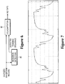
- Training sequence detection 80 may use algorithms or hardware circuitry to produce a detected training sequence from the digitized waveform record.
- Equalization adaptation (EQ) 82 may use algorithms or hardware circuitry to generate equalizer taps for the receiver 16 using the digitized waveform record and the detected training sequence. Equalizer adaptation 82 has a much better chance of succeeding when the training sequence is detected and becomes available. This solution is targeted to the real-time oscilloscopes, but the concept of this solution can be applied to sampling oscilloscopes as well.
- the detection of the training sequence 80 shown in Figure 6 takes the digitized waveform record as input and outputs a detected training bit sequence.
- the digitized waveform record acquired at the receiver end of channel 14 is substantially degraded such that its bit sequence doesn't appear apparent.
- the waveform generated using the digitized waveform record shown in Figure 7 is an example of a signal at the receiver end of the channel 14 having large ISI. If the bit sequence can be detected, then the equalization adaptation 82 can use the training bit sequence with the effects of the channel degradation being substantially reduced.
- One method to detect the training sequence is to provide an input signal processor to remove channel effects of channel 14 prior to sequence detection.
- the input signal processor may be a de-embed filter 84 that characterizes the channel 14 as is shown in Figure 8 .
- the channel 14 may be characterized using S- or T- parameters of the channel 14 and the de-embed filter is generated based on the channel characteristics.
- the digitized waveform record is de-embedded 84 using the de-embed filter to remove the effect of the channel so that the training sequence can be easily identified.
- the de-embedded digitized waveform record is provided to a sequence detector 86 that detects the training sequence. This method works the best when large ISI is introduced by the channel.
- the detection equalizer 88 is a detection equalizer 88 that generates an equalized digitized waveform record.
- the sequence detector 86 receives the equalized digitized waveform record and outputs a detected training sequence as is represented by Figure 9 . This method assumes no knowledge of the channel 14 characteristics.
- the detection equalizer 88 employs a Feed Forward Equalizer (FFE), a Decision Feedback equalizer (DFE), a Continuous-Time Linear Equalizer (CTLE) or the like for producing an equalized waveform output.
- FFE Feed Forward Equalizer
- DFE Decision Feedback equalizer
- CTLE Continuous-Time Linear Equalizer
- the detection equalizer 88 is part of the detection of the training sequence 80 of Figure 6 and not the equalizer in the EQ adaptation block 82.
- SAS-2 6G standard calls for 3-tap DFE as the receiver equalizer, which defines the output taps of the EQ adaptation block 82.
- the detection equalizer 88 shown in Figure 9 can have a multi-tap FFE/DFE, which has better capability to compensate the channel allowing the pattern sequence can be detected correctly.
- Figure 10 shows the waveform equalized with a multi-tap FFE, from which the sequence is reliably detected.
- Optional methods may exist for detecting training sequence if the test setup allows.
- One option is to use an analog waveform signal having a lower bit rate.
- Some transmitter chips 12 may be switchable, such as from 6 Gb/s to 3 Gb/s. On the same lossy channel 14, it is usually much easier to detect the training sequence from a 3Gb/s analog waveform signal than to detect the same training sequence from a 6Gb/s analog waveform signal.
- the analog waveform signal is sampled by the oscilloscope at the lower bit rate and a digitized waveform record is generated.
- the digitized waveform record at the lower bit rate is used for detecting the training sequence.
- the transmitter chip 12 is switched to the higher bit rate and another digitized waveform record of the analog waveform signal is acquired.
- the higher bit rate digitized waveform record is applied to the equalization adaptation 82 to generate a recovered clock and a re-sampled digitized waveform record.
- the measurement probe 44 is connected to the transmitter end 12 of the channel 14 and samples of the analog waveform signal are acquired by the oscilloscope to generate a digitized waveform record.
- the digitized waveform record of the analog waveform signal acquired at the transmitter is used for detecting the training sequence.
- the measurement probe 44 is connected to the receiver end 16 of the channel 14 and samples of the analog waveform signal are acquired by the oscilloscope to generate another digitized waveform record.
- the digitized waveform record acquired at the receiver end 16 of the channel 14 is applied to the equalization adaptation algorithms or hardware circuits 82 to generate a recovered clock and a re-sampled digitized waveform record.
- the digitized waveform record is processed for detection of the training sequence 80 using one or a combination of the above described methods and produces a detected training sequence.
- Sequence detection processes are well known in the art and need not to be described here.
- the detected training sequence can be saved for future use.
- a user interface 90 for activating the training sequence detection and saving the detected training sequence is shown in Figure 11 .
- a detect icon 92 is displayed on the interface 90 which when clicked with a mouse or touched with a finger activates detection algorithms for detecting the training sequence.
- the detected bit sequence is displayed in box 94 with the pattern length shown in display box 96.
- a file name box 98 is provided where a user enters a file name for the detected training sequence.
- a load icon 100 is clicked or touched that loads the detected training sequence into a file having the user defined file name.
- a save icon 102 is clicked or touched to save the training sequence file in the memory 70 of the oscilloscope 40.
- equalizer adaptation algorithms or hardware circuits 82 can use the training sequence to adapt the DFE taps of the SAS-2 6G equalizer standard or taps of other equalizers, such as FFE, on the waveform generated using the digitized waveform record, as shown in Figure 7 .
- Equalizer adaptation algorithms or hardware circuitry 82 in Figure 6 are shown in greater detail in the Figure 12 .
- the equalization adaptation algorithms or hardware circuits 82 initially recovers the clock 110 in the digitized waveform record.
- a clock recovery algorithm may be implemented in the oscilloscope 40, such as a clock recovery based on the nonlinear spectral line technique.
- the software clock recovery can be designed to emulate various PLLs.
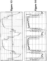
- Figure 13 shows the recovered clock 112 (dots) along with the waveform shown in Figure 7 .
- the distance between the clock recovery dots represents the clock period or unit interval of the digitized waveform record.
- the digitized waveform record signal is resampled 114 according to the signal bit rate.
- Real-time scopes usually sample at fixed sample rates that usually are not synchronized to the signal bit rates.
- resampling the digitized waveform record can be done accurately since the digitized waveform record is band limited by the scopes.
- De-emphasis is added on the digitized samples of the waveform record at bit center with the proper de-emphasis value based on the following criteria: 1) the transition density of the de-emphasized digitized waveform record should approximate the transition density of the training sequence; and 2) the de-emphasis value that provides the less mean square error is better.
- the re-sampled, de-emphasized digital samples of the digitized waveform record is cross correlated with the aligned training sequence to find the peak for determining the correct alignment.
- Figure 14 shows the training sequence aligned with the re-sampled digital samples of the digitized waveform record that has been properly de-emphasized.
- the de-emphasized digitized waveform samples (stars) have good correlation with the aligned training bit sequence (dots).
- standard equalization adaptation algorithms 118 can be executed to optimize the equalizer taps, such as the 3-tap DFE equalizer defined in the proposed SAS-2 6G standard.
- equalizer adaptation 82 the oscilloscope 40 can equalize the acquired digital waveform record using the adapted taps in a DFE equalizer.
- Figure 15 shows the eye diagram 120 of the digitized waveform record shown in Figure 7 , which is closed, and the eye diagram 122 opened by the equalizer using the optimized taps.
- the coefficients of the equalizer taps for the DFE equalizer defined in the proposed SAS-2 6G standard may be stored in the oscilloscope 60 and used in the design of DFE equalizers.
- a training sequence detection procedure using the real-time scopes has been described.
- the procedure uses the information about channel, or uses flexible equalization scheme, or uses available test setup to detect a training sequence even the sequence is difficult to recognize without special data processing.
- An equalization adaptation procedure is then introduced that uses the detected training sequence, and uses a de-emphasis technique to help sequence alignment.
Landscapes
- Engineering & Computer Science (AREA)
- Power Engineering (AREA)
- Computer Networks & Wireless Communication (AREA)
- Signal Processing (AREA)
- Dc Digital Transmission (AREA)
- Cable Transmission Systems, Equalization Of Radio And Reduction Of Echo (AREA)
- Signal Processing For Digital Recording And Reproducing (AREA)
Claims (11)
- Entzerrungssimulator mit Übungssequenzerfassung zur Verwendung in einem Oszilloskop (40), der eine digitalisierte Wellenformaufzeichnung aus einem Aufnehmen von Abtastungen eines analogen Wellenformsignals aus einer seriellen Datenverbindung erzeugt, umfassend:einen Eingangssignalprozessor (84, 88), der dazu angepasst ist, die digitalisierte Wellenformaufzeichnung zu empfangen und eine verarbeitete digitalisierte Wellenformaufzeichnung zu erstellen, bei der Kanaleffekte der seriellen Datenverbindung entfernt sind;einen Sequenzerfasser (86), der dazu angepasst ist, die verarbeitete digitalisierte Wellenformaufzeichnung zu empfangen und eine Übungssequenz zu erzeugen;einen Entzerrungsadapter (82), der dazu angepasst ist, die verarbeitete digitalisierte Wellenformaufzeichnung und die Übungssequenz zu empfangen und Entzerrerabgriffe zu erzeugen; undeinen Entzerrer, der dazu angepasst ist, die Entzerrerabgriffe und die verarbeitete digitalisierte Wellenformaufzeichnung zu empfangen und eine entzerrte digitalisierte Wellenformaufzeichnung zu erzeugen.
- Entzerrungssimulator mit Übungssequenzerfassung zur Verwendung in einem Oszilloskop (40) nach Anspruch 1, wobei der Eingangssignalprozessor (84) ein Enteinbettungsfilter umfasst, das Kanaleigenschaften der seriellen Datenverbindung darstellt, und wobei das Enteinbettungsfilter dazu angepasst ist, die digitalisierte Wellenformaufzeichnung zu empfangen und eine auf den Sequenzerfasser angewandte enteingebettete verarbeitete digitalisierte Wellenformaufzeichnung zu erzeugen.
- Entzerrungssimulator mit Übungssequenzerfassung zur Verwendung in einem Oszilloskop (40) nach Anspruch 1, wobei der Eingangssignalprozessor (88) einen Erfassungsentzerrer umfasst, der dazu angepasst ist, die digitalisierte Wellenformaufzeichnung zu empfangen und eine auf den Sequenzerfasser angewandte entzerrte verarbeitete digitalisierte Wellenformaufzeichnung zu erzeugen.
- Entzerrungssimulator mit Übungssequenzerfassung zur Verwendung in einem Oszilloskop (40) nach Anspruch 1, wobei der Entzerrungsadapter (82) ferner Folgendes umfasst:Mittel, die dazu angepasst sind, einen Taktgeber (110) aus der verarbeiteten digitalisierten Wellenformaufzeichnung wiederherzustellen, der eine Taktrate aufweist, die gleich der Bitrate des analogen Wellenformsignals ist;einen Wiederabtaster (114), der dazu angepasst ist, die verarbeitete digitalisierte Wellenformaufzeichnung und den wiederhergestellten Taktgeber zu empfangen und eine wiederabgetastete digitalisierte Wellenformaufzeichnung gemäß der Abtast-Bitrate des analogen Wellenformsignals unter Verwendung des wiederhergestellten Taktsignals zu erzeugen;Mittel, die dazu angepasst sind, die wiederabgetastete digitalisierte Wellenformaufzeichnung mit der Übungssequenz abzugleichen (116), um eine mit der wiederabgetasteten digitalisierten Wellenformaufzeichnung abgeglichene Übungssequenz zu erzeugen; undMittel, die dazu angepasst sind, die wiederabgetastete analoge Wellenform und die abgeglichene Übungssequenz zu empfangen (118) und Entzerrerabgriffe zu erzeugen.
- Verfahren zur Entzerrungssimulation unter Verwendung eines Oszilloskops (40), das die folgenden Schritte umfasst:a) Aufnehmen von Abtastungen eines analogen Wellenformsignals zum Erzeugen einer digitalisierten Wellenformaufzeichnung unter Verwendung des Oszilloskops (40);b) Erfassen einer Übungssequenz aus der digitalisierten Wellenformaufzeichnung;c) Wiederherstellen eines Taktsignals aus der digitalisierten Wellenformaufzeichnung, das eine Taktrate aufweist, die gleich der Bitrate des analogen Wellenformsignals ist;d) Wiederabtasten der digitalisierten Wellenformaufzeichnung gemäß der Bitrate des analogen Wellenformsignals unter Verwendung des wiederhergestellten Taktsignals;e) Anwenden von Deemphase an der Mitte der Bits in der wiederabgetasteten digitalisierten Wellenformaufzeichnung;f) Abgleichen der erfassten Übungssequenz mit der deemphasierten wiederabgetasteten digitalisierten Wellenformaufzeichnung;g) Erzeugen von Entzerrerabgriffen unter Verwendung der wiederabgetasteten digitalisierten Wellenformaufzeichnung und der abgeglichenen Übungssequenz; undh) Erzeugen einer entzerrten digitalisierten Wellenformaufzeichnung unter Verwendung der Entzerrerabgriffe und der wiederabgetasteten digitalisierten Wellenformaufzeichnung.
- Verfahren zur Entzerrungssimulation unter Verwendung eines Oszilloskops (40) nach Anspruch 5, wobei der Schritt des Erfassens der Übungssequenz die folgenden Schritte umfasst:b.1) Erzeugen eines Kanal-Enteinbettungsfilters als eine Funktion der Kanaleigenschaften; undb.2) Erzeugen einer enteingebetteten digitalisierten Wellenformaufzeichnung zum Erfassen der Übungssequenz durch Anwenden der digitalisierten Wellenformaufzeichnung auf das Enteinbettungsfilter.
- Verfahren zur Entzerrungssimulation unter Verwendung eines Oszilloskops (40) nach Anspruch 5, wobei der Schritt des Erfassens der Übungssequenz den Schritt des Erzeugens einer entzerrten digitalisierten Wellenformaufzeichnung zum Erfassen der Übungssequenz unter Verwendung eines Mehrfachabgriffentzerrers umfasst.
- Verfahren zur Entzerrungssimulation unter Verwendung eines Oszilloskops (40) nach Anspruch 5, wobei der Schritt des Erfassens der Übungssequenz die folgenden Schritte umfasst:b.1) Senken der Bitrate des analogen Wellenformsignals;b.2) Aufnehmen von Abtastungen des analogen Wellenformsignals mit gesenkter Bitrate unter Verwendung des Oszilloskops zum Erzeugen einer digitalisierten Wellenformaufzeichnung zum Erfassen der Übungssequenz;b.3) Erhöhen der Bitrate des analogen Wellenformsignals; undb.4) Aufnehmen von Abtastungen des analogen Wellenformsignals mit erhöhter Bitrate unter Verwendung des Oszilloskops zum Erzeugen einer weiteren digitalisierten Wellenformaufzeichnung zum Wiederherstellen des Taktsignals und Wiederabtasten der anderen digitalisierten Wellenformaufzeichnung.
- Verfahren zur Entzerrungssimulation unter Verwendung eines Oszilloskops (40) nach Anspruch 5, wobei der Schritt des Erfassens der Übungssequenz die folgenden Schritte umfasst:b.1) Anschließen einer Messsonde an einer Sendeseite eines Kanals;b.2) Aufnehmen von Abtastungen des analogen Wellenformsignals an der Sendeseite des Kanals unter Verwendung des Oszilloskops zum Erzeugen einer digitalisierten Wellenformaufzeichnung zum Erfassen der Übungssequenz;b.3) Anschließen der Messsonde an einer Empfangsseite des Kanals; undb.4) Aufnehmen von Abtastungen des analogen Wellenformsignals an der Empfangsseite des Kanals unter Verwendung des Oszilloskops zum Erzeugen einer weiteren digitalisierten Wellenformaufzeichnung zum Wiederherstellen des Taktsignals und Wiederabtasten der anderen digitalisierten Wellenformaufzeichnung.
- Verfahren zur Entzerrungssimulation unter Verwendung eines Oszilloskops (40) nach Anspruch 5, wobei der Schritt des Anwendens von Deemphase den Schritt des Definierens eines Deemphasewerts als eine Funktion der Übergangsdichte der deemphasierten wiederabgetasteten digitalisierten Wellenformaufzeichnung umfasst, die annähernd der Übergangsdichte der erfassten Übungssequenz entspricht und einen minimalen mittleren quadratischen Fehler bereitstellt.
- Verfahren zur Entzerrungssimulation unter Verwendung eines Oszilloskops (40) nach Anspruch 5, wobei der Schritt des Abgleichens ferner den Schritt des Kreuzkorrelierens der erfassten Übungssequenz mit der deemphasierten wiederabgetasteten digitalisierten Wellenformaufzeichnung zum Finden eines Spitzenwerts zum Bestimmen des korrekten Abgleichs umfasst.
Applications Claiming Priority (2)
| Application Number | Priority Date | Filing Date | Title |
|---|---|---|---|
| US4929808P | 2008-04-30 | 2008-04-30 | |
| US12/423,604 US8374231B2 (en) | 2008-04-30 | 2009-04-14 | Equalization simulator with training sequence detection for an oscilloscope |
Publications (2)
| Publication Number | Publication Date |
|---|---|
| EP2113775A1 EP2113775A1 (de) | 2009-11-04 |
| EP2113775B1 true EP2113775B1 (de) | 2017-09-13 |
Family
ID=40872374
Family Applications (1)
| Application Number | Title | Priority Date | Filing Date |
|---|---|---|---|
| EP09251155.9A Active EP2113775B1 (de) | 2008-04-30 | 2009-04-22 | Ausgleichssimulator mit Übungssequenzerfassung für ein Oszilloskop |
Country Status (4)
| Country | Link |
|---|---|
| US (1) | US8374231B2 (de) |
| EP (1) | EP2113775B1 (de) |
| JP (1) | JP5344342B2 (de) |
| CN (1) | CN101581734B (de) |
Families Citing this family (21)
| Publication number | Priority date | Publication date | Assignee | Title |
|---|---|---|---|---|
| US9048941B2 (en) * | 2010-01-22 | 2015-06-02 | Mentor Graphics Corporation | Characteristic response extraction for non-linear transmit channels |
| TW201202921A (en) * | 2010-07-08 | 2012-01-16 | Hon Hai Prec Ind Co Ltd | SAS interface testing tool |
| US9191245B2 (en) | 2011-03-08 | 2015-11-17 | Tektronix, Inc. | Methods and systems for providing optimum decision feedback equalization of high-speed serial data links |
| US8855186B2 (en) | 2011-03-08 | 2014-10-07 | Tektronix, Inc. | Methods and systems for providing optimum decision feedback equalization of high-speed serial data links |
| US10073750B2 (en) * | 2012-06-11 | 2018-09-11 | Tektronix, Inc. | Serial data link measurement and simulation system |
| US8977139B2 (en) * | 2012-10-29 | 2015-03-10 | Finisar Corporation | Integrated circuits in optical receivers |
| US20150084655A1 (en) * | 2013-09-25 | 2015-03-26 | Tektronix, Inc. | Switched load time-domain reflectometer de-embed probe |
| US20150084660A1 (en) * | 2013-09-25 | 2015-03-26 | Tektronix, Inc. | Time-domain reflectometer de-embed probe |
| DE102013221394A1 (de) * | 2013-10-22 | 2015-04-23 | Rohde & Schwarz Gmbh & Co. Kg | Messgerät und Verfahren zur Messung eines Hochfrequenzsignals mit Deembedding |
| CN105282065B (zh) | 2014-07-18 | 2020-09-15 | 特克特朗尼克公司 | 用于提供高速串行数据链路的最优dfe的方法和系统 |
| US9596074B2 (en) * | 2015-05-01 | 2017-03-14 | Tektronix, Inc. | Clock recovery for data signals |
| US11018964B2 (en) * | 2016-01-19 | 2021-05-25 | Tektronix, Inc. | Selective extraction of network link training information |
| US9729119B1 (en) * | 2016-03-04 | 2017-08-08 | Atmel Corporation | Automatic gain control for received signal strength indication |
| US10209276B2 (en) | 2016-08-15 | 2019-02-19 | Tektronix, Inc. | Jitter and eye contour at BER measurements after DFE |
| US9800438B1 (en) * | 2016-10-25 | 2017-10-24 | Xilinx, Inc. | Built-in eye scan for ADC-based receiver |
| EP3361269B1 (de) * | 2017-02-10 | 2022-03-30 | Rohde & Schwarz GmbH & Co. KG | Dynamisches messsystem und verfahren zum messen eines dynamischen datensignals |
| US10075286B1 (en) * | 2017-03-13 | 2018-09-11 | Tektronix, Inc. | Equalizer for limited intersymbol interference |
| US10069653B1 (en) * | 2017-05-12 | 2018-09-04 | Seagate Technology Llc | Blind partial response equalization |
| US10255448B1 (en) | 2017-10-11 | 2019-04-09 | International Business Machines Corporation | Data security using high speed serial equalization |
| FR3124881A1 (fr) * | 2021-06-30 | 2023-01-06 | Universite de Bordeaux | Système et méthode pour la génération de signaux destinés à des tests pédagogiques |
| US11804991B2 (en) * | 2021-10-18 | 2023-10-31 | Mediatek Inc. | Sequence detection device using path-selective sequence detection and associated sequence detection method |
Family Cites Families (13)
| Publication number | Priority date | Publication date | Assignee | Title |
|---|---|---|---|---|
| JPH03238361A (ja) * | 1990-02-16 | 1991-10-24 | Yokogawa Electric Corp | デジタルオシロスコープ |
| US5245630A (en) * | 1991-04-09 | 1993-09-14 | Tektronix, Inc. | Equalized eye pattern instrument |
| JPH07218548A (ja) * | 1994-01-31 | 1995-08-18 | Sony Tektronix Corp | 波形測定装置 |
| JP2001285152A (ja) * | 2000-03-21 | 2001-10-12 | Motorola Inc | マルチパスデジタル無線通信において複数の遅延波を検出する方法および受信機 |
| US7050491B2 (en) * | 2001-10-15 | 2006-05-23 | Mcdonald James Douglas | Adaptive equalization of digital modulating signal recovered from amplitude-modulated signal subject to multipath |
| CN101438494B (zh) * | 2004-04-09 | 2012-02-22 | 上海奇普科技有限公司 | 由从信道接收的信号的采样导出均衡值的装置和方法 |
| US20060182231A1 (en) * | 2005-01-27 | 2006-08-17 | Kan Tan | Apparatus and method for processing acquired signals for measuring the impedance of a device under test |
| US7660372B2 (en) * | 2005-02-09 | 2010-02-09 | Broadcom Corporation | Efficient header acquisition |
| US20070276614A1 (en) * | 2006-05-25 | 2007-11-29 | Kan Tan | De-embed method for multiple probes coupled to a device under test |
| US7460983B2 (en) * | 2006-08-23 | 2008-12-02 | Tektronix, Inc. | Signal analysis system and calibration method |
| US20070276622A1 (en) * | 2006-05-25 | 2007-11-29 | Pickerd John J | Calibration method and apparatus using a trigger signal synchronous with a signal under test |
| CN100512457C (zh) * | 2006-03-15 | 2009-07-08 | 天津市德力电子仪器有限公司 | 数字电视信号综合分析仪 |
| US7408363B2 (en) * | 2006-08-23 | 2008-08-05 | Tektronix, Inc. | Signal analysis system and calibration method for processing acquires signal samples with an arbitrary load |
-
2009
- 2009-04-14 US US12/423,604 patent/US8374231B2/en active Active
- 2009-04-22 EP EP09251155.9A patent/EP2113775B1/de active Active
- 2009-04-22 JP JP2009104394A patent/JP5344342B2/ja active Active
- 2009-04-30 CN CN200910141999.0A patent/CN101581734B/zh active Active
Non-Patent Citations (1)
| Title |
|---|
| None * |
Also Published As
| Publication number | Publication date |
|---|---|
| EP2113775A1 (de) | 2009-11-04 |
| CN101581734B (zh) | 2014-03-05 |
| US8374231B2 (en) | 2013-02-12 |
| JP2009271063A (ja) | 2009-11-19 |
| CN101581734A (zh) | 2009-11-18 |
| JP5344342B2 (ja) | 2013-11-20 |
| US20100085362A1 (en) | 2010-04-08 |
Similar Documents
| Publication | Publication Date | Title |
|---|---|---|
| EP2113775B1 (de) | Ausgleichssimulator mit Übungssequenzerfassung für ein Oszilloskop | |
| US8855186B2 (en) | Methods and systems for providing optimum decision feedback equalization of high-speed serial data links | |
| US9191245B2 (en) | Methods and systems for providing optimum decision feedback equalization of high-speed serial data links | |
| KR102164627B1 (ko) | 송신기와 수신기 사이에서 데이터 신호를 전달하는 채널을 포함하는 고속 링크를 최적화하는 시스템 및 그 방법, 그리고 송신기와 수신기 사이의 채널을 특성화하는 방법 | |
| US9148315B1 (en) | Method and apparatus for reducing jitter in overlaid traces of an eye diagram of a recovered signal generated based on a received data signal | |
| CN107770107B (zh) | 测试和测量系统以及在测试和测量系统中采用dfe的方法 | |
| US8599909B2 (en) | Serial link voltage margin determination in mission mode | |
| JP2022183142A (ja) | 通信リンク等化処理、コンピューティング装置及びイコライザ最適化方法 | |
| CN106100817B (zh) | 用于数据信号的改善的时钟恢复 | |
| US8705601B2 (en) | Apparatus and method for varying inter symbol interference and bandwidth extension pre-emphasis on a high speed digital signal | |
| CN108574652B (zh) | 用于受限符号间干扰的均衡器 | |
| US20190068411A1 (en) | Equalizer For Limited Intersymbol Interference | |
| CN105282065B (zh) | 用于提供高速串行数据链路的最优dfe的方法和系统 | |
| JP2023168323A (ja) | 試験測定装置及びイコライザ・タップ値を求める方法 | |
| US20250097080A1 (en) | Digital serializer/deserializer circuit and data eye monitoring method thereof | |
| US12519565B1 (en) | Method and system for equalizing digital signals using partial response maximum likelihood sequence equalization | |
| US7236550B1 (en) | Method and apparatus for tail cancellation equalization | |
| CN1983832A (zh) | 一种确定滤波器系数的方法和系统 | |
| US20230204629A1 (en) | Method of ctle estimation using channel step-response for transmitter link equalization test | |
| US20060215745A1 (en) | Direct determination equalizer system | |
| JP2025010062A (ja) | 試験測定装置及びトランスミッタの校正方法 | |
| CN117061018A (zh) | 发射机均衡器抽头提取 |
Legal Events
| Date | Code | Title | Description |
|---|---|---|---|
| PUAI | Public reference made under article 153(3) epc to a published international application that has entered the european phase |
Free format text: ORIGINAL CODE: 0009012 |
|
| AK | Designated contracting states |
Kind code of ref document: A1 Designated state(s): AT BE BG CH CY CZ DE DK EE ES FI FR GB GR HR HU IE IS IT LI LT LU LV MC MK MT NL NO PL PT RO SE SI SK TR |
|
| 17P | Request for examination filed |
Effective date: 20100428 |
|
| 17Q | First examination report despatched |
Effective date: 20100531 |
|
| GRAP | Despatch of communication of intention to grant a patent |
Free format text: ORIGINAL CODE: EPIDOSNIGR1 |
|
| INTG | Intention to grant announced |
Effective date: 20170518 |
|
| GRAS | Grant fee paid |
Free format text: ORIGINAL CODE: EPIDOSNIGR3 |
|
| GRAA | (expected) grant |
Free format text: ORIGINAL CODE: 0009210 |
|
| AK | Designated contracting states |
Kind code of ref document: B1 Designated state(s): AT BE BG CH CY CZ DE DK EE ES FI FR GB GR HR HU IE IS IT LI LT LU LV MC MK MT NL NO PL PT RO SE SI SK TR |
|
| REG | Reference to a national code |
Ref country code: GB Ref legal event code: FG4D |
|
| REG | Reference to a national code |
Ref country code: CH Ref legal event code: EP |
|
| REG | Reference to a national code |
Ref country code: IE Ref legal event code: FG4D |
|
| REG | Reference to a national code |
Ref country code: AT Ref legal event code: REF Ref document number: 928681 Country of ref document: AT Kind code of ref document: T Effective date: 20171015 |
|
| REG | Reference to a national code |
Ref country code: DE Ref legal event code: R096 Ref document number: 602009048296 Country of ref document: DE |
|
| REG | Reference to a national code |
Ref country code: NL Ref legal event code: MP Effective date: 20170913 |
|
| REG | Reference to a national code |
Ref country code: LT Ref legal event code: MG4D |
|
| PG25 | Lapsed in a contracting state [announced via postgrant information from national office to epo] |
Ref country code: NO Free format text: LAPSE BECAUSE OF FAILURE TO SUBMIT A TRANSLATION OF THE DESCRIPTION OR TO PAY THE FEE WITHIN THE PRESCRIBED TIME-LIMIT Effective date: 20171213 Ref country code: SE Free format text: LAPSE BECAUSE OF FAILURE TO SUBMIT A TRANSLATION OF THE DESCRIPTION OR TO PAY THE FEE WITHIN THE PRESCRIBED TIME-LIMIT Effective date: 20170913 Ref country code: FI Free format text: LAPSE BECAUSE OF FAILURE TO SUBMIT A TRANSLATION OF THE DESCRIPTION OR TO PAY THE FEE WITHIN THE PRESCRIBED TIME-LIMIT Effective date: 20170913 Ref country code: HR Free format text: LAPSE BECAUSE OF FAILURE TO SUBMIT A TRANSLATION OF THE DESCRIPTION OR TO PAY THE FEE WITHIN THE PRESCRIBED TIME-LIMIT Effective date: 20170913 Ref country code: LT Free format text: LAPSE BECAUSE OF FAILURE TO SUBMIT A TRANSLATION OF THE DESCRIPTION OR TO PAY THE FEE WITHIN THE PRESCRIBED TIME-LIMIT Effective date: 20170913 |
|
| REG | Reference to a national code |
Ref country code: AT Ref legal event code: MK05 Ref document number: 928681 Country of ref document: AT Kind code of ref document: T Effective date: 20170913 |
|
| PG25 | Lapsed in a contracting state [announced via postgrant information from national office to epo] |
Ref country code: ES Free format text: LAPSE BECAUSE OF FAILURE TO SUBMIT A TRANSLATION OF THE DESCRIPTION OR TO PAY THE FEE WITHIN THE PRESCRIBED TIME-LIMIT Effective date: 20170913 Ref country code: BG Free format text: LAPSE BECAUSE OF FAILURE TO SUBMIT A TRANSLATION OF THE DESCRIPTION OR TO PAY THE FEE WITHIN THE PRESCRIBED TIME-LIMIT Effective date: 20171213 Ref country code: GR Free format text: LAPSE BECAUSE OF FAILURE TO SUBMIT A TRANSLATION OF THE DESCRIPTION OR TO PAY THE FEE WITHIN THE PRESCRIBED TIME-LIMIT Effective date: 20171214 Ref country code: LV Free format text: LAPSE BECAUSE OF FAILURE TO SUBMIT A TRANSLATION OF THE DESCRIPTION OR TO PAY THE FEE WITHIN THE PRESCRIBED TIME-LIMIT Effective date: 20170913 |
|
| PG25 | Lapsed in a contracting state [announced via postgrant information from national office to epo] |
Ref country code: NL Free format text: LAPSE BECAUSE OF FAILURE TO SUBMIT A TRANSLATION OF THE DESCRIPTION OR TO PAY THE FEE WITHIN THE PRESCRIBED TIME-LIMIT Effective date: 20170913 |
|
| PG25 | Lapsed in a contracting state [announced via postgrant information from national office to epo] |
Ref country code: CZ Free format text: LAPSE BECAUSE OF FAILURE TO SUBMIT A TRANSLATION OF THE DESCRIPTION OR TO PAY THE FEE WITHIN THE PRESCRIBED TIME-LIMIT Effective date: 20170913 Ref country code: RO Free format text: LAPSE BECAUSE OF FAILURE TO SUBMIT A TRANSLATION OF THE DESCRIPTION OR TO PAY THE FEE WITHIN THE PRESCRIBED TIME-LIMIT Effective date: 20170913 Ref country code: PL Free format text: LAPSE BECAUSE OF FAILURE TO SUBMIT A TRANSLATION OF THE DESCRIPTION OR TO PAY THE FEE WITHIN THE PRESCRIBED TIME-LIMIT Effective date: 20170913 |
|
| PG25 | Lapsed in a contracting state [announced via postgrant information from national office to epo] |
Ref country code: SK Free format text: LAPSE BECAUSE OF FAILURE TO SUBMIT A TRANSLATION OF THE DESCRIPTION OR TO PAY THE FEE WITHIN THE PRESCRIBED TIME-LIMIT Effective date: 20170913 Ref country code: IS Free format text: LAPSE BECAUSE OF FAILURE TO SUBMIT A TRANSLATION OF THE DESCRIPTION OR TO PAY THE FEE WITHIN THE PRESCRIBED TIME-LIMIT Effective date: 20180113 Ref country code: AT Free format text: LAPSE BECAUSE OF FAILURE TO SUBMIT A TRANSLATION OF THE DESCRIPTION OR TO PAY THE FEE WITHIN THE PRESCRIBED TIME-LIMIT Effective date: 20170913 Ref country code: EE Free format text: LAPSE BECAUSE OF FAILURE TO SUBMIT A TRANSLATION OF THE DESCRIPTION OR TO PAY THE FEE WITHIN THE PRESCRIBED TIME-LIMIT Effective date: 20170913 Ref country code: IT Free format text: LAPSE BECAUSE OF FAILURE TO SUBMIT A TRANSLATION OF THE DESCRIPTION OR TO PAY THE FEE WITHIN THE PRESCRIBED TIME-LIMIT Effective date: 20170913 |
|
| REG | Reference to a national code |
Ref country code: DE Ref legal event code: R097 Ref document number: 602009048296 Country of ref document: DE |
|
| PLBE | No opposition filed within time limit |
Free format text: ORIGINAL CODE: 0009261 |
|
| STAA | Information on the status of an ep patent application or granted ep patent |
Free format text: STATUS: NO OPPOSITION FILED WITHIN TIME LIMIT |
|
| PG25 | Lapsed in a contracting state [announced via postgrant information from national office to epo] |
Ref country code: DK Free format text: LAPSE BECAUSE OF FAILURE TO SUBMIT A TRANSLATION OF THE DESCRIPTION OR TO PAY THE FEE WITHIN THE PRESCRIBED TIME-LIMIT Effective date: 20170913 |
|
| 26N | No opposition filed |
Effective date: 20180614 |
|
| PGFP | Annual fee paid to national office [announced via postgrant information from national office to epo] |
Ref country code: GB Payment date: 20180427 Year of fee payment: 10 |
|
| PG25 | Lapsed in a contracting state [announced via postgrant information from national office to epo] |
Ref country code: MC Free format text: LAPSE BECAUSE OF FAILURE TO SUBMIT A TRANSLATION OF THE DESCRIPTION OR TO PAY THE FEE WITHIN THE PRESCRIBED TIME-LIMIT Effective date: 20170913 Ref country code: SI Free format text: LAPSE BECAUSE OF FAILURE TO SUBMIT A TRANSLATION OF THE DESCRIPTION OR TO PAY THE FEE WITHIN THE PRESCRIBED TIME-LIMIT Effective date: 20170913 |
|
| REG | Reference to a national code |
Ref country code: CH Ref legal event code: PL |
|
| REG | Reference to a national code |
Ref country code: BE Ref legal event code: MM Effective date: 20180430 |
|
| REG | Reference to a national code |
Ref country code: IE Ref legal event code: MM4A |
|
| PG25 | Lapsed in a contracting state [announced via postgrant information from national office to epo] |
Ref country code: LU Free format text: LAPSE BECAUSE OF NON-PAYMENT OF DUE FEES Effective date: 20180422 |
|
| PG25 | Lapsed in a contracting state [announced via postgrant information from national office to epo] |
Ref country code: CH Free format text: LAPSE BECAUSE OF NON-PAYMENT OF DUE FEES Effective date: 20180430 Ref country code: BE Free format text: LAPSE BECAUSE OF NON-PAYMENT OF DUE FEES Effective date: 20180430 Ref country code: LI Free format text: LAPSE BECAUSE OF NON-PAYMENT OF DUE FEES Effective date: 20180430 |
|
| PG25 | Lapsed in a contracting state [announced via postgrant information from national office to epo] |
Ref country code: IE Free format text: LAPSE BECAUSE OF NON-PAYMENT OF DUE FEES Effective date: 20180422 Ref country code: FR Free format text: LAPSE BECAUSE OF NON-PAYMENT OF DUE FEES Effective date: 20180430 |
|
| GBPC | Gb: european patent ceased through non-payment of renewal fee |
Effective date: 20190422 |
|
| PG25 | Lapsed in a contracting state [announced via postgrant information from national office to epo] |
Ref country code: GB Free format text: LAPSE BECAUSE OF NON-PAYMENT OF DUE FEES Effective date: 20190422 Ref country code: MT Free format text: LAPSE BECAUSE OF NON-PAYMENT OF DUE FEES Effective date: 20180422 |
|
| PG25 | Lapsed in a contracting state [announced via postgrant information from national office to epo] |
Ref country code: TR Free format text: LAPSE BECAUSE OF FAILURE TO SUBMIT A TRANSLATION OF THE DESCRIPTION OR TO PAY THE FEE WITHIN THE PRESCRIBED TIME-LIMIT Effective date: 20170913 |
|
| PG25 | Lapsed in a contracting state [announced via postgrant information from national office to epo] |
Ref country code: PT Free format text: LAPSE BECAUSE OF FAILURE TO SUBMIT A TRANSLATION OF THE DESCRIPTION OR TO PAY THE FEE WITHIN THE PRESCRIBED TIME-LIMIT Effective date: 20170913 Ref country code: HU Free format text: LAPSE BECAUSE OF FAILURE TO SUBMIT A TRANSLATION OF THE DESCRIPTION OR TO PAY THE FEE WITHIN THE PRESCRIBED TIME-LIMIT; INVALID AB INITIO Effective date: 20090422 |
|
| PG25 | Lapsed in a contracting state [announced via postgrant information from national office to epo] |
Ref country code: CY Free format text: LAPSE BECAUSE OF FAILURE TO SUBMIT A TRANSLATION OF THE DESCRIPTION OR TO PAY THE FEE WITHIN THE PRESCRIBED TIME-LIMIT Effective date: 20170913 Ref country code: MK Free format text: LAPSE BECAUSE OF NON-PAYMENT OF DUE FEES Effective date: 20170913 |
|
| P01 | Opt-out of the competence of the unified patent court (upc) registered |
Effective date: 20230530 |
|
| PGFP | Annual fee paid to national office [announced via postgrant information from national office to epo] |
Ref country code: DE Payment date: 20250428 Year of fee payment: 17 |