EP2113696B1 - Dispositif de soupape - Google Patents
Dispositif de soupape Download PDFInfo
- Publication number
- EP2113696B1 EP2113696B1 EP20090010697 EP09010697A EP2113696B1 EP 2113696 B1 EP2113696 B1 EP 2113696B1 EP 20090010697 EP20090010697 EP 20090010697 EP 09010697 A EP09010697 A EP 09010697A EP 2113696 B1 EP2113696 B1 EP 2113696B1
- Authority
- EP
- European Patent Office
- Prior art keywords
- valve
- arrangement according
- valve arrangement
- pilot
- main
- Prior art date
- Legal status (The legal status is an assumption and is not a legal conclusion. Google has not performed a legal analysis and makes no representation as to the accuracy of the status listed.)
- Active
Links
- 239000012530 fluid Substances 0.000 claims description 12
- 238000000034 method Methods 0.000 claims description 3
- 238000011144 upstream manufacturing Methods 0.000 claims description 3
- 230000005540 biological transmission Effects 0.000 claims 1
- 238000005452 bending Methods 0.000 description 12
- 230000001276 controlling effect Effects 0.000 description 12
- 230000010355 oscillation Effects 0.000 description 11
- 239000012528 membrane Substances 0.000 description 10
- 210000002023 somite Anatomy 0.000 description 5
- 230000008901 benefit Effects 0.000 description 4
- 230000001105 regulatory effect Effects 0.000 description 4
- 230000008859 change Effects 0.000 description 3
- 239000004020 conductor Substances 0.000 description 3
- 230000007423 decrease Effects 0.000 description 3
- 230000001939 inductive effect Effects 0.000 description 3
- ATUOYWHBWRKTHZ-UHFFFAOYSA-N Propane Chemical compound CCC ATUOYWHBWRKTHZ-UHFFFAOYSA-N 0.000 description 2
- 230000000712 assembly Effects 0.000 description 2
- 238000000429 assembly Methods 0.000 description 2
- 238000010276 construction Methods 0.000 description 2
- 210000004072 lung Anatomy 0.000 description 2
- 230000002829 reductive effect Effects 0.000 description 2
- 230000009471 action Effects 0.000 description 1
- 230000004913 activation Effects 0.000 description 1
- 239000003990 capacitor Substances 0.000 description 1
- 239000000919 ceramic Substances 0.000 description 1
- 230000008878 coupling Effects 0.000 description 1
- 238000010168 coupling process Methods 0.000 description 1
- 238000005859 coupling reaction Methods 0.000 description 1
- 230000003247 decreasing effect Effects 0.000 description 1
- 238000010586 diagram Methods 0.000 description 1
- 230000000694 effects Effects 0.000 description 1
- 238000009429 electrical wiring Methods 0.000 description 1
- 230000005284 excitation Effects 0.000 description 1
- 239000012212 insulator Substances 0.000 description 1
- 239000000463 material Substances 0.000 description 1
- 239000002184 metal Substances 0.000 description 1
- 230000003534 oscillatory effect Effects 0.000 description 1
- 230000003071 parasitic effect Effects 0.000 description 1
- 230000036961 partial effect Effects 0.000 description 1
- 239000001294 propane Substances 0.000 description 1
- 230000010349 pulsation Effects 0.000 description 1
- 230000009467 reduction Effects 0.000 description 1
- 230000000284 resting effect Effects 0.000 description 1
- 230000002441 reversible effect Effects 0.000 description 1
- XLYOFNOQVPJJNP-UHFFFAOYSA-N water Substances O XLYOFNOQVPJJNP-UHFFFAOYSA-N 0.000 description 1
Images


Classifications
-
- F—MECHANICAL ENGINEERING; LIGHTING; HEATING; WEAPONS; BLASTING
- F16—ENGINEERING ELEMENTS AND UNITS; GENERAL MEASURES FOR PRODUCING AND MAINTAINING EFFECTIVE FUNCTIONING OF MACHINES OR INSTALLATIONS; THERMAL INSULATION IN GENERAL
- F16K—VALVES; TAPS; COCKS; ACTUATING-FLOATS; DEVICES FOR VENTING OR AERATING
- F16K31/00—Actuating devices; Operating means; Releasing devices
- F16K31/12—Actuating devices; Operating means; Releasing devices actuated by fluid
- F16K31/36—Actuating devices; Operating means; Releasing devices actuated by fluid in which fluid from the circuit is constantly supplied to the fluid motor
- F16K31/40—Actuating devices; Operating means; Releasing devices actuated by fluid in which fluid from the circuit is constantly supplied to the fluid motor with electrically-actuated member in the discharge of the motor
- F16K31/402—Actuating devices; Operating means; Releasing devices actuated by fluid in which fluid from the circuit is constantly supplied to the fluid motor with electrically-actuated member in the discharge of the motor acting on a diaphragm
-
- Y—GENERAL TAGGING OF NEW TECHNOLOGICAL DEVELOPMENTS; GENERAL TAGGING OF CROSS-SECTIONAL TECHNOLOGIES SPANNING OVER SEVERAL SECTIONS OF THE IPC; TECHNICAL SUBJECTS COVERED BY FORMER USPC CROSS-REFERENCE ART COLLECTIONS [XRACs] AND DIGESTS
- Y10—TECHNICAL SUBJECTS COVERED BY FORMER USPC
- Y10T—TECHNICAL SUBJECTS COVERED BY FORMER US CLASSIFICATION
- Y10T137/00—Fluid handling
- Y10T137/206—Flow affected by fluid contact, energy field or coanda effect [e.g., pure fluid device or system]
-
- Y—GENERAL TAGGING OF NEW TECHNOLOGICAL DEVELOPMENTS; GENERAL TAGGING OF CROSS-SECTIONAL TECHNOLOGIES SPANNING OVER SEVERAL SECTIONS OF THE IPC; TECHNICAL SUBJECTS COVERED BY FORMER USPC CROSS-REFERENCE ART COLLECTIONS [XRACs] AND DIGESTS
- Y10—TECHNICAL SUBJECTS COVERED BY FORMER USPC
- Y10T—TECHNICAL SUBJECTS COVERED BY FORMER US CLASSIFICATION
- Y10T137/00—Fluid handling
- Y10T137/8593—Systems
- Y10T137/87917—Flow path with serial valves and/or closures
- Y10T137/87925—Separable flow path section, valve or closure in each
Definitions
- the invention relates to a valve arrangement, which is particularly suitable for gas applications, and a method for controlling such a valve arrangement.
- servo valves are often used, which are controlled by a pilot valve.
- a valve arrangement is for example the DE 100 06 600 B4 refer to.
- This valve arrangement has a main valve with a valve closure member, which is associated with a valve seat.
- a spring biases the valve closure member against the valve seat.
- a fluid-operated drive means in the form of a housing arranged in a membrane, which is connected via a valve rod with the valve closure member.
- an electromagnetic pilot valve is provided, which is designed as a changeover valve.
- the valve assembly with small electrical Open or close services.
- the solenoid of the pilot valve must be constantly energized. Even if a holding current reduction is performed here, this leads to a non-negligible power consumption. This can not be reduced arbitrarily.
- the pilot valve must switch safely in case of power failure in the required to effect the closed position of the valve assembly position.
- a corresponding return spring is required, which is able to safely overcome all the remanence forces that can occur in a magnetic circuit.
- the holding current of the pilot valve must then be dimensioned in order to overcome the closing spring in the controlled state.
- valve arrangement does not permit modulation of the gas flow. Rather, it is an on / off valve with the intermediate values can not be set permanently. If gas appliances with varying power requirements are to be controlled by such a valve, additional modulation valves are required.
- valve body can be brought by a magnetic drive to oscillate. This measure serves to reduce and regulate the flow rate.
- the operation of the pilot valve with AC voltage opens the possibility to use the main valve not only as open / close valve but also as a modulation valve, which can be set between the open position and the closed position various intermediate positions. With a corresponding stepless adjustment of the control signal of the pilot valve thus a continuous adjustment of the main valve can be achieved.
- To adjust the passage of the pilot valve it is possible to change the drive amplitude of the AC voltage or its frequency. However, it is preferred to operate with constant frequency and amplitude and square wave signals whose duty cycle is changed according to a default signal. By means of the pulse-pause ratio of the alternating voltage driving the pilot valve, it is thus possible to control the pilot fluid flow and thus also the opening of the main valve.
- a valve arrangement can be operated for example as part of a control device as a pressure regulator or as a flow regulator to produce a desired constant gas pressure or a desired predetermined gas flow.
- the control device is connected to a pressure sensor or flow meter placed at a suitable place.
- the corresponding AC signal can be generated easily and with low loss.
- the operation of the pilot valve is inaudible.
- the opening and closing intervals of the piezoelectric actuator follow at such a high speed that the pilot fluid flow is uniform and the main valve driving means does not vibrate. Ultimately, this is achieved by the drive means forms a mechanical low-pass filter, wherein the operating frequency of the pilot valve is far above the corner frequency.
- the modulation of the pilot valve and thus also the opening of the main valve by modulating the duty cycle of the AC voltage can be done in stages, almost infinitely or completely continuously. This can be achieved with low-loss digital means and can be carried out for example by a microcomputer.
- the piezoelectric actuator a device connected in parallel, which allows a galvanic current flow.
- a resistor can be used for this purpose, which dissipates charges which are seated on the piezoelement in the event of a fault.
- such resistance is always associated with power losses.
- the piezoelectric pilot valve is designed such that, by design, a gas flow can only occur if the piezoelectric actuator vibrates, can be dispensed with a parallel to the piezoelectric actuator current path.
- an inductive component for example a coil
- this forms with the piezoelectric component a parallel resonant circuit whose resonant frequency is lower than the frequency of the driving AC voltage or coincides with this.
- This ensures that only a small parasitic current flow through the inductive component occurs and the electrical losses are kept low.
- the supply current which must apply the control device, particularly low and free of reactive power.
- relatively high oscillation amplitudes can be achieved on the piezoelectric actuator with low control currents.
- the coil causes an immediate discharge of the piezoelectric actuator, ie its short circuit, so that it returns to its relaxed state practically instantaneously.
- the pilot valve is designed to vibrate only when it is in electrical resonance with the connected coil, then the drive frequency must be relatively consistent with the resonant frequency to open the pilot valve. This has the advantage of additional security for itself.
- the pilot valve remains closed when no voltage is applied, when any voltage is applied, or when there is vibration at a frequency other than the resonant frequency. An error case in which random but undesirably just the resonance frequency is generated is very unlikely.
- the piezoelectric component is preferably a bending oscillator. With this, a sufficient stroke can be achieved at an oscillation frequency of a few tens of kilohertz in order to release suitable gas flows for controlling gas valves. It can be used to create gas valves that are suitable for controlling gas flows in the range of a few kilowatts to over a hundred kilowatts.
- bending vibrator can serve a conventional piezoceramic strip or bar whose flat sides carry electrodes.
- a bending oscillator instead of a conventional bending oscillator, which has a substantially nostinunver Sliches element and arranged parallel to this and connected to this a longer-variable piezo stack.
- This arrangement has the advantage of achieving high deflections with low drive voltages, so that relatively large pilot gas flows can be controlled.
- the pilot valve on two alternately releasable outputs, which are both closed in the idle state of the pilot valve, ie without controlling the same.
- driving the piezoelectric actuator with positive or negative polarity either only one or only the other output is released. Both outputs can thus not simultaneously, but only temporally nested, that are released alternately. This is achieved, for example, by controlling both outputs of the pilot valve from one and the same piezoelectric actuator, for example flexible oscillators be, which bulges alternately in one direction or the other when driving.
- the correspondingly assigned outputs can be released alternately by these two valve closure members when the bending oscillator vibrates.
- a pilot valve for example, two successively arranged main valves can be controlled. Both main valves only receive gas when the flexural vibrates. The two outputs of the pilot valve then deliver in rapid succession intermittently small gas portions, which combine in each case to a pilot gas flow for controlling the first and the second main valve.
- the valve arrangement according to the invention which only opens when the piezoelectric actuator of the pilot valve oscillates, offers extremely high safety.
- the two series-connected main valves can be controlled by the oscillating switching pilot valve separately pulse width modulated.
- a bipolar AC voltage is used, the positive and negative wave of which are independently pulse width modulated can.
- the two main gas valves arranged in series can be controlled independently, whereby, for example, a very large control range, Zündgas horr or other modes can be realized.
- the first valve can be used as a pressure regulator and the second as a modulation valve.
- the two piezo-controlled main valves before or after a magnetically actuated open / close valve or to replace one of the main valves by such.
- the known and recognized safety properties of inexpensive solenoid valves can be connected to the possibilities of good controllability of the piezo-controlled servo valves.
- the solenoid valve provides the classification in the desired safety class and with the controlled by the piezo pilot valve main valve (s) can be set to the desired gas pressure and / or the desired flow.
- the space enclosed by the housing of the pilot valve serves as a buffer.
- the housing leads an input, which is associated with a valve closure member.
- From the housing leads out an exit, which is also associated with a valve closure member.
- Both valve closure members are moved, for example, by one and the same piezoelectric element, both valve closure members sit on their respective valve seat when the actuator is not activated, ie relaxed and at rest.
- the actuator is preferably a bending oscillator. Because both valve closure members spaced from each other are arranged on the bending oscillator can the input is opened when the flexural resonator swings in one direction while the input is closed and the output is opened when the actuator bulges in the opposite direction.
- Such a pilot valve can be used to directly control small gas flows as well as to drive servovalves. It has the advantage that it only lets gas through when the actuator vibrates. A deflection of the actuator only in one or only in the other direction causes no permanent gas flow but only the admission or omission of a minimum gas portion.
- the valve can also be used as a gas meter. For a given gas pressure, the number of vibration cycles corresponds to a quantity of gas passed. An electronic counter connected to the drive AC voltage of the valve thus indicates a value proportional to the amount of gas passed.
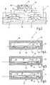
- FIG. 1 a valve assembly 1 is illustrated, which is in principle for controlling different fluid media, but in particular for controlling a gas flow can be used.
- To the valve assembly 1 includes two main valves 2, 3, which are arranged in a line 4 behind each other.
- the main valves 2, 3 are controlled by a common pilot valve 5, which may be formed as a separate module or combined with one of the main valves 2, 3 or with both main valves 2, 3 to form an assembly.
- the main valves 2, 3 may for example be housed in a common housing. They are each designed as so-called servo valves and each have a drive device 6, 7, which, as FIG. 2 can be formed by a membrane 8, 9.
- the membrane 8, 9 is arranged in a housing 10, 11. This can, as in FIG.
- FIG. 2 schematically illustrates part of a valve housing 12 be.
- the housings 10, 11 may also be offset from the valve housing 12.
- the membranes 8, 9 divide in the housings 10, 11 from at least one working chamber 13, 14, which are connected via fluid channels 15, 16 throttled connected to the main valves 2, 3 upstream portion of the line 4.
- the membranes 8, 9 are connected, for example, via push rods or valve spindles each with a valve closure member 17, 18.
- the valve closure members 17, 18, as FIG. 2 illustrated by a central portion or part of the membrane 8, 9 or a directly connected to the membrane 8, 9 part formed.
- valve closing springs 19, 20 are provided, which bias the valve closure members 17, 18 against valve seats 21, 22.
- the path from the inlet 23 to the outlet 24 of the valve assembly 1 is blocked by two main valves 2, 3.
- an intermediate chamber 25 is formed between the main valves 2, 3.
- sensors may be attached.
- a flow sensor can be used to detect the flow. On the basis of the detected flow value can be adjusted with the valve 3, for example, a desired flow value.
- a desired flow can then be e.g. be set with the valve 3 by this is adjusted according to its known characteristic to a corresponding opening value.
- the desired flow can then be regulated or adjusted with the valve 3 fairly accurately.
- the working chambers 13, 14 are connected via suitable lines or channels 26, 27 with a first and a second input 28, 29 of the pilot valve 5.
- This has a housing 30 in which one or more piezoelectric actuators 31 are arranged. These lie with a designed as a valve closure member surface area 32, 33 at valve seats, which are associated with the inputs 28, 29.
- the actuators 31 own spring action is in FIG. 2 illustrated by a spring symbol. From the housing 30th leads out a channel which is connected via a line 34 to the downstream side of the valve assembly 1, ie the output 24.
- the valve assembly 1 is connected to a control device 35, which controls the piezoelectric actuator 31.
- the latter is for example a bending oscillator, which is supplied by the control device 35 for opening the main valves 2, 3 with an AC voltage. This applies both when the surfaces 32, 33 on one and the same piezoelectric actuator 31 as well as when they are provided on separate actuators.
- the actuator or actuators are driven so that the surfaces 32, 33 move in opposite directions, i. that the inputs 28, 29 are alternately released.
- the control device 35 outputs an AC signal to the actuator 31 (or the actuators, if there are several) so that they oscillate.
- the surfaces 32, 33 thus periodically lift from their respective valve seats.
- the actuator 31 preferably oscillates inaudibly at a frequency above 20 kHz or below 20 Hz or 16 Hz, ie with an ultrasonic or infrasonic frequency.
- the inputs 28, 29 are released, that is connected via the line 34 to the output 24.
- the flow resistance of the thus released channel is low, at least less than the flow resistance of the channels 15, 16.
- the valve closure members 17, 18 lift off from their valve seats 21, 22 and release the gas flow.
- the flow resistance can be varied, flows with the fluid or gas from the working chambers 13, 14.
- the position of the valve closure members 17, 18 can be selectively regulated in order to release the gas flow neither completely nor to block completely but to throttle in the desired manner, for example, to achieve a constant gas pressure or a constant gas flow.
- the main valve 2 can be used as a pressure regulator for keeping constant Gas pressure in the intermediate chamber 5 can be used.
- the following in the flow direction of the main valve 3 can then be used for example as a flow regulator to regulate starting from a constant form in the intermediate chamber 25, the gas flow.
- FIG. 4 illustrates a preferred embodiment of the pilot valve 5.
- the actuator 31 is formed by a piezo bending oscillator, which is connected at one end 36 to the housing 30 and fixed there, for example, firmly clamped.
- the piezoelectric vibrator is formed for example by a narrow flat strip of piezoceramic material. It is provided with electrodes and is designed so that when exposed to a voltage of a first polarity, such as FIG. 5 illustrated bulges in a first direction while buckling in the opposite direction upon connection of a voltage with reverse polarity, such as FIG. 6 illustrated.
- the surfaces 32, 33 are formed, for example, on smaller projections which are arranged on a common flat side of the actuating member 31. They close the inputs 28, 29 when the actuator 31 is de-energized. This condition is in FIG. 4 illustrated.
- the actuator 31 When the actuator 31 is connected to a voltage of a first polarity, the surface 33 lifts from the associated valve seat and the input 29 is released. In this case, the piezoelectric actuator 31 is supported with the surface 32 on the valve seat of the input 28, which thus remains closed.
- the piezoelectric actuator 31 If the piezoelectric actuator 31 is acted upon by an opposing voltage, it bulges in the opposite direction. It now rests with its surface 33 against the valve seat of the inlet 29, while the surface 32 lifts off from the valve seat of the inlet 28. Thus, the input 28 is enabled while the input 29 remains closed.
- the actuator 31 is biased with a bias in the direction of the inputs 28, 29.
- This bias is in FIGS. 4, 5 and 6 symbolized by an arrow 37.
- the bias voltage is thus supported over the surface 32 or the surface 33. If there is no activation, the bias voltage according to arrow 37 is transmitted via both surfaces 32, 33.
- the bias can be generated by a separate spring element or by the actuator 31 inherent elasticity.
- the pilot valve 5 according to the FIGS. 4 to 6 is particularly suitable for controlling the main valves 2, 3 according to FIG. 2 and 3 ,
- the two working chambers 13, 14 are only relieved of pressure when the actuator 31 oscillates. If it does not oscillate but in one or the other position according to FIG. 5 or FIG. 6 remains, at least one of the main valves 2, 3 is closed. Thus, each failure of the control device 35 leads to the closing of at least one of the valves 2, 3.
- the piezoelectric actuator 31 has been discharged by external resistors, by internal resistance or other measures, and the state to FIG. 4 assumes both main valves 2, 3 are closed.
- the actuation of the actuating member 31 can with an AC voltage according to FIGS. 11 and 12 respectively.
- the alternating voltage is preferably bipolar, ie it has a positive wave I and a negative wave II with respect to the reference voltage zero.
- the positive shaft I controls, for example, the bending of the actuator 31 according to FIG. 5 while the negative wave II, the bending of the actuator 31 according to FIG. 6 affected.
- Both waves I, II can be modulated in terms of their pulse-pause ratio, as the wave trains III, IV show.
- the wave trains V, VI can take different pulse-pause ratios.
- the gas outflows through the inputs 28, 29 are independently controllable. For example, as the waves VII, VIII show, opening of one of the valves can be almost or completely dispensed with, so that the actuating member 31 opens only one of the main valves 2, 3 and leaves the other closed.
- ignition gas is discharged from the intermediate chamber 25 via a connection 38.
- the pilot valve 5 is actuated in an oscillating manner, wherein the control alternating voltage, for example according to FIG. 12 is so asymmetrical that only the upstream main valve 2 is opened, the main valve 3, however, remains closed.
- Ignition gas can be discharged via port 38, whereby the ignition gas quantity is also modulated by modulating the opening of the main valve 2 is controllable.
- the modulation can be achieved by determining a suitable duty ratio of the curve VIII (FIG. FIG. 12 ), which serves to control the main valve 2.
- FIG. 8 1 illustrates an embodiment for a pilot valve 5, which has two actuators 31a, 31b, which are actuated independently of each other and connected to corresponding outputs of the control device 35.
- Both control elements 31a, 31b each have the surfaces 32, 33 already discussed for closing the associated inputs 28, 29.
- the actuators 31a, 31b close the inputs 28, 29.
- the actuators 31a, 31b are each set in oscillating motion, wherein the frequency and / or the duty ratio and / or the Amplitude of the flow resistance is regulated at the respective valve seat. Otherwise, the previous description applies.
- FIG. 9 illustrates the structure of the actuator 31 in one embodiment. It consists of a support 39, which is elongated and strip-shaped and in FIG. 9 is arranged horizontally.
- the bendable, but hardly stretchable, ie, stretch-resistant support 39 is, for example, a metal tongue or a ceramic tongue.
- a stack structure consisting of individual piezo elements 40, 41, 42, etc. applied, which change their thickness when subjected to voltage, based on the in FIG. 9 horizontal longitudinal direction of the carrier 39 is measured parallel to this.
- the individual piezo elements 40 to 42 are separated from each other by insulator layers and each provided with two electrodes.
- Left electrodes are each connected to a first conductor 44.
- FIG. 9 Left electrodes are each connected to a first conductor 44.
- each piezo element 40 to 42 are connected to a second conductor 45. Between the comb-like interdigitated electrodes of the conductors 44, 45, the piezoelectric elements 40, 41, 42 and in each case between said insulating layers are alternately provided.
- Such a stack construction has at relatively low applied control voltages a relatively large change in length, which is converted by the fixed connection to the carrier 39 in a bending movement.
- FIG. 10 illustrates the electrical wiring of the piezoelectric actuator 31 having outer electrodes and itself forms a vibratable system. It is externally connected to an inductance L in order to form with the capacitance of the actuating element 31 a resonant circuit whose resonant frequency is at or below the frequency of the connected, output from the control device 35 AC voltage.
- the inductive element L closes the actuator 31 short, ie it causes its discharge and thus the return to its extended position in which the connected valves are closed.
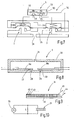
- FIGS. 13 to 15 illustrate a further developed embodiment of the pilot valve 5, which can be used to control a single main valve 2 as well as in duplicate for controlling two main valves 2, 3. It can also be used for direct control of relatively small, for example, high energy Gas flows, eg for small propane gas appliances, serve.
- This pilot valve 5 is in its construction largely with the pilot valve 5 after the FIGS. 4 to 6 however, the output leading to line 34 is missing.
- the terminals 28, 29, for example the terminal 28 as usual the input while the other, also referred to above as the input terminal 29, now designated 46 and forms an output. Otherwise, the previous description applies without restriction.
- the actuator 31 includes with its surfaces 32, 33, both the input 28 and the output 46.
- the actuator 31 is biased to the corresponding valve seats.
- the bias is by a in the FIGS. 13 to 15 drawn spring 47 causes, said spring may be both formed and provided as a separate element and may be formed by the bias of the actuator 31 itself.
- the input 28 and the output 46 can not be enabled at the same time. You can only open alternately by the actuator 31 is deflected in one direction or the other direction.
- FIG. 14 illustrates the release of the output 46 with the input 28 closed at the same time.
- FIG. 15 on the other hand illustrates the release of the input 28 while closing the output 46.
- the control of this pilot valve 5 is preferably carried out with a symmetrical AC voltage, for example according to FIG. 11 right. If the gas flow to be throttled, for example, to a waveform according to FIG. 11 left, whereby the opening times of input 28 and output 46 are smaller and thus the transmitted gas portions are smaller. Thus, the gas flow through the pilot valve 5 can be steplessly controlled.
- the gas flow by increasing or decreasing the drive frequency and thus the oscillation frequency of the actuator 31. Since exactly one gas portion is allowed to pass through each oscillation cycle, the gas flow increases with increasing frequency. Likewise, it can be influenced to a small extent by influencing the oscillation amplitude.
- the pilot valve 5 after the FIGS. 13 to 15 is intrinsically safe. It can not be opened by forward or backward gas pressure. In each case at least one of the two partial valves at the inlet 28 or outlet 46 is closed. In addition, it can not be opened by applying a DC voltage in one direction or the other (polarity). To release a gas flow, the application of an alternating voltage is required, which leads to a sufficiently large oscillation of the actuating member 31, preferably in the ultrasonic range.
- the pilot valve 5 is suitable for metering small gas flows or other compressible fluid media. Incompressible media (water, oil) can be controlled with this valve if the housing 30 is elastic, has an elastic portion or if there is some other elastic buffer between the inlet and the outlet.
- a valve arrangement has for control purposes a pilot valve 5 with piezoelectric actuator 31.
- the pilot valve 5 is driven with an alternating voltage, so that its actuating member 31 oscillates to release a gas flow.
Claims (14)
- Agencement de vannes (1), en particulier agencement de vannes de gaz, comprenant deux vannes principales (2, 3) qui sont disposées l'une derrière l'autre et qui comportent chacune un organe de fermeture de vanne (17, 18) relié à un dispositif d'entraînement actionné par fluide (6, 7), comprenant une vanne pilote (5) qui est reliée aux dispositifs d'entraînement (6, 7) pour commander celles-ci par un flux de fluide pilote respectif et qui comporte au moins un organe d'actionnement piézoélectrique (31, 31a, 31b) pour influencer le flux de fluide pilote, et comprenant un dispositif de commande (35) qui est relié à la vanne pilote (5) et qui applique à celle-ci une tension alternative pour ouvrir les vannes principales (2, 3).
- Agencement de vannes selon la revendication 1, caractérisé en ce que la tension alternative présente une forme de signal rectangulaire.
- Agencement de vannes selon la revendication 2, caractérisé en ce que le dispositif de commande (35) est conçu pour moduler le rapport cyclique de la tension alternative.
- Agencement de vannes selon la revendication 1, caractérisé en ce que le composant piézoélectrique (31) est un résonateur de flexion.
- Agencement de vannes selon la revendication 4, caractérisé en ce que le résonateur de flexion présente une pile d'éléments piézoélectriques (41, 42, 43) dont la longueur est variable piézoélectriquement.
- Agencement de vannes selon la revendication 5, caractérisé en ce que la pile d'éléments piézoélectriques (41, 42, 43) est reliée d'un côté à un élément porteur rigide en extension (39) qui s'étend parallèlement à la direction longitudinale de la pile d'éléments piézoélectriques (41, 42, 43).
- Agencement de vannes selon la revendication 1, caractérisé en ce que la vanne pilote (5) présente deux raccords (28, 29, 46) pouvant être ouverts alternativement, lesquels peuvent être reliés aux dispositifs d'entraînement (6, 7) des vannes principales (2, 3).
- Agencement de vannes selon la revendication 1, caractérisé en ce que le dispositif de commande (35) est conçu pour délivrer une tension alternative bipolaire.
- Agencement de vannes selon la revendication 8, caractérisé en ce que la tension alternative est modulable en largeur d'impulsion dans au moins une polarité.
- Agencement de vannes selon la revendication 1, caractérisé en ce qu'un capteur relié au dispositif de commande (35) est disposé dans ou sur une chambre (25) faisant suite à la vanne principale (2).
- Agencement de vannes selon la revendication 10, caractérisé en ce que le capteur est un capteur de pression et en ce que le dispositif de commande régule la pression qui règne dans la chambre (25) au moyen de la vanne principale (2).
- Agencement de vannes selon les revendications 7 et 11, caractérisé en ce que, pour régler des flux de gaz souhaités, le dispositif de commande (35) règle la deuxième vanne principale (3) à des positions correspondantes, définissant les flux de gaz souhaités, en fonction de sa caractéristique de passage.
- Agencement de vannes selon la revendication 1, caractérisé en ce qu'une vanne à commande électromagnétique est implantée en amont ou en aval de la vanne principale (2).
- Procédé de commande d'un agencement de vannes selon la revendication 1, comprenant deux vannes principales (2, 3) et au moins une vanne pilote, (5) qui les commande, procédé dans lequel, pour ouvrir les vannes principales (2, 3), on actionne la vanne pilote (5) de manière oscillante entre position d'ouverture et position de fermeture en lui appliquant une tension alternative.
Applications Claiming Priority (2)
| Application Number | Priority Date | Filing Date | Title |
|---|---|---|---|
| DE200510018730 DE102005018730B4 (de) | 2005-04-22 | 2005-04-22 | Ventilanordung mit Piezosteuerung |
| EP20060002520 EP1715229B1 (fr) | 2005-04-22 | 2006-02-08 | Dispositif de soupape |
Related Parent Applications (2)
| Application Number | Title | Priority Date | Filing Date |
|---|---|---|---|
| EP20060002520 Division EP1715229B1 (fr) | 2005-04-22 | 2006-02-08 | Dispositif de soupape |
| EP06002520.2 Division | 2006-02-08 |
Publications (3)
| Publication Number | Publication Date |
|---|---|
| EP2113696A2 EP2113696A2 (fr) | 2009-11-04 |
| EP2113696A3 EP2113696A3 (fr) | 2010-06-02 |
| EP2113696B1 true EP2113696B1 (fr) | 2011-07-20 |
Family
ID=36685942
Family Applications (2)
| Application Number | Title | Priority Date | Filing Date |
|---|---|---|---|
| EP20060002520 Expired - Fee Related EP1715229B1 (fr) | 2005-04-22 | 2006-02-08 | Dispositif de soupape |
| EP20090010697 Active EP2113696B1 (fr) | 2005-04-22 | 2006-02-08 | Dispositif de soupape |
Family Applications Before (1)
| Application Number | Title | Priority Date | Filing Date |
|---|---|---|---|
| EP20060002520 Expired - Fee Related EP1715229B1 (fr) | 2005-04-22 | 2006-02-08 | Dispositif de soupape |
Country Status (4)
| Country | Link |
|---|---|
| US (1) | US7520487B2 (fr) |
| EP (2) | EP1715229B1 (fr) |
| CN (1) | CN100472109C (fr) |
| DE (2) | DE102005018730B4 (fr) |
Cited By (16)
| Publication number | Priority date | Publication date | Assignee | Title |
|---|---|---|---|---|
| US8839815B2 (en) | 2011-12-15 | 2014-09-23 | Honeywell International Inc. | Gas valve with electronic cycle counter |
| US8899264B2 (en) | 2011-12-15 | 2014-12-02 | Honeywell International Inc. | Gas valve with electronic proof of closure system |
| US8905063B2 (en) | 2011-12-15 | 2014-12-09 | Honeywell International Inc. | Gas valve with fuel rate monitor |
| US8947242B2 (en) | 2011-12-15 | 2015-02-03 | Honeywell International Inc. | Gas valve with valve leakage test |
| US9074770B2 (en) | 2011-12-15 | 2015-07-07 | Honeywell International Inc. | Gas valve with electronic valve proving system |
| US9234661B2 (en) | 2012-09-15 | 2016-01-12 | Honeywell International Inc. | Burner control system |
| US9557059B2 (en) | 2011-12-15 | 2017-01-31 | Honeywell International Inc | Gas valve with communication link |
| DE102016106909A1 (de) * | 2016-04-14 | 2017-10-19 | Hoerbiger Automatisierungstechnik Holding Gmbh | Elektropneumatische Ventilgruppe |
| US9995486B2 (en) | 2011-12-15 | 2018-06-12 | Honeywell International Inc. | Gas valve with high/low gas pressure detection |
| US10024439B2 (en) | 2013-12-16 | 2018-07-17 | Honeywell International Inc. | Valve over-travel mechanism |
| US10203049B2 (en) | 2014-09-17 | 2019-02-12 | Honeywell International Inc. | Gas valve with electronic health monitoring |
| US10215291B2 (en) | 2013-10-29 | 2019-02-26 | Honeywell International Inc. | Regulating device |
| US10564062B2 (en) | 2016-10-19 | 2020-02-18 | Honeywell International Inc. | Human-machine interface for gas valve |
| US10697815B2 (en) | 2018-06-09 | 2020-06-30 | Honeywell International Inc. | System and methods for mitigating condensation in a sensor module |
| US10851993B2 (en) | 2011-12-15 | 2020-12-01 | Honeywell International Inc. | Gas valve with overpressure diagnostics |
| US11073281B2 (en) | 2017-12-29 | 2021-07-27 | Honeywell International Inc. | Closed-loop programming and control of a combustion appliance |
Families Citing this family (15)
| Publication number | Priority date | Publication date | Assignee | Title |
|---|---|---|---|---|
| US20090032746A1 (en) * | 2007-07-31 | 2009-02-05 | Caterpillar Inc. | Piezo-electric actuated valve |
| US9103335B2 (en) * | 2008-06-27 | 2015-08-11 | Ge Oil & Gas Compression Systems, Llc | System and devices including valves coupled to electric devices and methods of making, using, and operating the same |
| JP5631631B2 (ja) * | 2010-05-21 | 2014-11-26 | 株式会社サタケ | 圧電式バルブ及び該圧電式バルブを利用する光学式粒状物選別機 |
| US9846440B2 (en) | 2011-12-15 | 2017-12-19 | Honeywell International Inc. | Valve controller configured to estimate fuel comsumption |
| US9835265B2 (en) | 2011-12-15 | 2017-12-05 | Honeywell International Inc. | Valve with actuator diagnostics |
| CN102797872B (zh) * | 2012-09-01 | 2014-01-15 | 安徽理工大学 | 一种基于超磁致伸缩薄膜驱动器的平面线圈驱动式微阀 |
| US10422531B2 (en) | 2012-09-15 | 2019-09-24 | Honeywell International Inc. | System and approach for controlling a combustion chamber |
| US9841122B2 (en) | 2014-09-09 | 2017-12-12 | Honeywell International Inc. | Gas valve with electronic valve proving system |
| US10503181B2 (en) | 2016-01-13 | 2019-12-10 | Honeywell International Inc. | Pressure regulator |
| JP6714397B2 (ja) | 2016-03-08 | 2020-06-24 | 株式会社サタケ | 圧電式バルブ、該圧電式バルブの駆動方法、及び該圧電式バルブを利用した噴風手段を備える光学式粒状物選別機 |
| DE102017105039A1 (de) | 2017-03-09 | 2018-09-13 | Marco Systemanalyse Und Entwicklung Gmbh | Verfahren zur Regelung einer piezoelektrischen Stellvorrichtung |
| CN109424535B (zh) * | 2017-08-21 | 2021-03-09 | 研能科技股份有限公司 | 共振式压电气体泵的节能控制方法 |
| DE102017131101B4 (de) * | 2017-12-22 | 2023-04-20 | Bürkert Werke GmbH & Co. KG | Ventilbaugruppe |
| IL268254A (en) * | 2019-07-24 | 2021-01-31 | Ham Let Israel Canada Ltd | Flow control accessory |
| EP4314571A1 (fr) * | 2021-03-26 | 2024-02-07 | Scuola Superiore di Studi Universitari e di Perfezionamento Sant'Anna | Dispositif et système servant à la régulation d'un écoulement de fluide |
Family Cites Families (13)
| Publication number | Priority date | Publication date | Assignee | Title |
|---|---|---|---|---|
| DE3315972A1 (de) * | 1983-05-02 | 1984-11-08 | Automatic Switch Co., Florham Park, N. J. | Ventil |
| DE3739048C2 (de) * | 1987-11-17 | 2001-08-09 | Buerkert Gmbh | Mehrwegeventil |
| FR2635163B1 (fr) * | 1988-08-02 | 1990-11-16 | Intertechnique Sa | Dispositif d'alimentation en fluide, a clapet pilote |
| DE3929889A1 (de) * | 1989-09-08 | 1991-03-14 | Bauknecht Hausgeraete | Sicherheitseinrichtung fuer einen wasserzulauf |
| DE3936619A1 (de) * | 1989-11-03 | 1991-05-08 | Man Nutzfahrzeuge Ag | Verfahren zum einspritzen eines brennstoffes in einen brennraum einer luftverdichtenden, selbstzuendenden brennkraftmaschine, sowie vorrichtungen zur durchfuehrung dieses verfahrens |
| US5251148A (en) * | 1990-06-01 | 1993-10-05 | Valtek, Inc. | Integrated process control valve |
| AT396392B (de) * | 1991-09-30 | 1993-08-25 | Hoerbiger Fluidtechnik Gmbh | Piezo-ventil |
| US6357335B1 (en) * | 1999-12-23 | 2002-03-19 | Sox Corporation | Pneumatic volume booster for valve positioner |
| DE10006600B4 (de) * | 2000-02-15 | 2004-02-26 | Hans-Jochen Dr. Schwarz | Gasventil und Verfahren zum Betrieb eines Gasventils |
| ATE284490T1 (de) * | 2000-05-25 | 2004-12-15 | Festo Ag & Co | Ventileinrichtung |
| FR2821915B1 (fr) * | 2001-03-06 | 2004-03-05 | App S Electro Mecaniques Du Fa | Dispositif de commande et de securite de debit gazeux |
| DE10303856B3 (de) * | 2003-01-30 | 2004-04-29 | Dbt Automation Gmbh | Vorrichtung zum Schalten eines Ventils |
| JP4344164B2 (ja) * | 2003-04-18 | 2009-10-14 | 株式会社サタケ | 圧電式エアバルブおよび複合圧電式エアバルブ |
-
2005
- 2005-04-22 DE DE200510018730 patent/DE102005018730B4/de not_active Expired - Fee Related
-
2006
- 2006-02-08 EP EP20060002520 patent/EP1715229B1/fr not_active Expired - Fee Related
- 2006-02-08 EP EP20090010697 patent/EP2113696B1/fr active Active
- 2006-02-08 DE DE200650005149 patent/DE502006005149D1/de active Active
- 2006-04-11 US US11/402,360 patent/US7520487B2/en not_active Expired - Fee Related
- 2006-04-21 CN CNB2006100792877A patent/CN100472109C/zh not_active Expired - Fee Related
Cited By (19)
| Publication number | Priority date | Publication date | Assignee | Title |
|---|---|---|---|---|
| US8839815B2 (en) | 2011-12-15 | 2014-09-23 | Honeywell International Inc. | Gas valve with electronic cycle counter |
| US8899264B2 (en) | 2011-12-15 | 2014-12-02 | Honeywell International Inc. | Gas valve with electronic proof of closure system |
| US8905063B2 (en) | 2011-12-15 | 2014-12-09 | Honeywell International Inc. | Gas valve with fuel rate monitor |
| US8947242B2 (en) | 2011-12-15 | 2015-02-03 | Honeywell International Inc. | Gas valve with valve leakage test |
| US9074770B2 (en) | 2011-12-15 | 2015-07-07 | Honeywell International Inc. | Gas valve with electronic valve proving system |
| US9557059B2 (en) | 2011-12-15 | 2017-01-31 | Honeywell International Inc | Gas valve with communication link |
| US10851993B2 (en) | 2011-12-15 | 2020-12-01 | Honeywell International Inc. | Gas valve with overpressure diagnostics |
| US10697632B2 (en) | 2011-12-15 | 2020-06-30 | Honeywell International Inc. | Gas valve with communication link |
| US9995486B2 (en) | 2011-12-15 | 2018-06-12 | Honeywell International Inc. | Gas valve with high/low gas pressure detection |
| US9234661B2 (en) | 2012-09-15 | 2016-01-12 | Honeywell International Inc. | Burner control system |
| US10215291B2 (en) | 2013-10-29 | 2019-02-26 | Honeywell International Inc. | Regulating device |
| US10024439B2 (en) | 2013-12-16 | 2018-07-17 | Honeywell International Inc. | Valve over-travel mechanism |
| US10203049B2 (en) | 2014-09-17 | 2019-02-12 | Honeywell International Inc. | Gas valve with electronic health monitoring |
| US10619655B2 (en) | 2016-04-14 | 2020-04-14 | Hoerbiger Automatsierungstechnik Holding Gmbh | Electropneumatic valve assembly |
| DE102016106909A8 (de) * | 2016-04-14 | 2017-12-14 | Hoerbiger Automatisierungstechnik Holding Gmbh | Elektropneumatische Ventilgruppe |
| DE102016106909A1 (de) * | 2016-04-14 | 2017-10-19 | Hoerbiger Automatisierungstechnik Holding Gmbh | Elektropneumatische Ventilgruppe |
| US10564062B2 (en) | 2016-10-19 | 2020-02-18 | Honeywell International Inc. | Human-machine interface for gas valve |
| US11073281B2 (en) | 2017-12-29 | 2021-07-27 | Honeywell International Inc. | Closed-loop programming and control of a combustion appliance |
| US10697815B2 (en) | 2018-06-09 | 2020-06-30 | Honeywell International Inc. | System and methods for mitigating condensation in a sensor module |
Also Published As
| Publication number | Publication date |
|---|---|
| CN1877171A (zh) | 2006-12-13 |
| CN100472109C (zh) | 2009-03-25 |
| US7520487B2 (en) | 2009-04-21 |
| US20060260701A1 (en) | 2006-11-23 |
| DE502006005149D1 (de) | 2009-12-03 |
| EP2113696A3 (fr) | 2010-06-02 |
| EP1715229B1 (fr) | 2009-10-21 |
| EP1715229A2 (fr) | 2006-10-25 |
| EP1715229A3 (fr) | 2007-06-20 |
| DE102005018730A1 (de) | 2006-10-26 |
| EP2113696A2 (fr) | 2009-11-04 |
| DE102005018730B4 (de) | 2008-04-03 |
Similar Documents
| Publication | Publication Date | Title |
|---|---|---|
| EP2113696B1 (fr) | Dispositif de soupape | |
| DE69737377T2 (de) | Steuerventil und Flüssigkeitszuführungs-/Entleerungs- system | |
| DE3926348C2 (fr) | ||
| EP0366605B1 (fr) | Dispositif de commande électrohydraulique ou -pneumatique | |
| DE1963745A1 (de) | Kompensiertes elektromechanisches Regelventil | |
| DE1523502A1 (de) | Monostabiler Stroemungsmittel-Schalter | |
| DE3137609T5 (en) | Gas-flow regulating system | |
| WO2011050784A1 (fr) | Actionneur | |
| CH713460A2 (de) | Schwingsaitensensor und Schwingsaite für einen Schwingsaitensensor. | |
| DE19825210C2 (de) | Schaltungsanordnung zur dynamischen Ansteuerung von keramischen Festkörperaktoren | |
| DE102010035747A1 (de) | Ventileinheit | |
| DE102005038891A1 (de) | Aktoreinrichtung, insbesondere für eine Einspritzvorrichtung | |
| DE102013111025A1 (de) | Ventileinrichtung zum gesteuerten Einleiten eines Blasmediums | |
| DE1437412B2 (de) | Elektrostatischer elektroakustischer wandler | |
| DE102015103936A1 (de) | Schalldämmeinrichtung mit einer Membran und einer Masse | |
| WO2007082601A1 (fr) | Contrôleur à modulation d'impulsions en durée à auto-excitation destiné à un moteur à ultrasons monophase | |
| DE102006048307A1 (de) | Mittels des inversen Piezoeffekts betätigbares Federelement | |
| EP2923183B1 (fr) | Débitmètre à ultrasons | |
| DE19834673B4 (de) | Spannungstransformator und dessen Verwendung | |
| EP1086499A1 (fr) | Dispositif d'entrainement | |
| DE102017214697A1 (de) | Schaltungsanordnung und Ansteuerungsverfahren für einen piezohydraulischen Aktor | |
| DE3627325A1 (de) | Elektrische druckumwandlungs-steuervorrichtung | |
| WO1992015812A1 (fr) | Procede de commande d'une vanne a tiroir conçue comme une vanne magnetique et vanne magnetique permettant de mettre en ×uvre le procede | |
| DE102005015765B4 (de) | Mittels des inversen Piezoeffekts betätigter Antrieb | |
| DE3116316A1 (de) | Elektromagnetische stelleinrichtung fuer ein stellglied |
Legal Events
| Date | Code | Title | Description |
|---|---|---|---|
| PUAI | Public reference made under article 153(3) epc to a published international application that has entered the european phase |
Free format text: ORIGINAL CODE: 0009012 |
|
| 17P | Request for examination filed |
Effective date: 20090820 |
|
| AC | Divisional application: reference to earlier application |
Ref document number: 1715229 Country of ref document: EP Kind code of ref document: P |
|
| AK | Designated contracting states |
Kind code of ref document: A2 Designated state(s): DE FR GB IT |
|
| PUAL | Search report despatched |
Free format text: ORIGINAL CODE: 0009013 |
|
| AK | Designated contracting states |
Kind code of ref document: A3 Designated state(s): DE FR GB IT |
|
| RIC1 | Information provided on ipc code assigned before grant |
Ipc: F16K 31/02 20060101AFI20110127BHEP |
|
| GRAP | Despatch of communication of intention to grant a patent |
Free format text: ORIGINAL CODE: EPIDOSNIGR1 |
|
| GRAS | Grant fee paid |
Free format text: ORIGINAL CODE: EPIDOSNIGR3 |
|
| GRAA | (expected) grant |
Free format text: ORIGINAL CODE: 0009210 |
|
| AC | Divisional application: reference to earlier application |
Ref document number: 1715229 Country of ref document: EP Kind code of ref document: P |
|
| AK | Designated contracting states |
Kind code of ref document: B1 Designated state(s): DE FR GB IT |
|
| REG | Reference to a national code |
Ref country code: GB Ref legal event code: FG4D Free format text: NOT ENGLISH |
|
| REG | Reference to a national code |
Ref country code: DE Ref legal event code: R096 Ref document number: 502006009876 Country of ref document: DE Effective date: 20110915 |
|
| PLBE | No opposition filed within time limit |
Free format text: ORIGINAL CODE: 0009261 |
|
| STAA | Information on the status of an ep patent application or granted ep patent |
Free format text: STATUS: NO OPPOSITION FILED WITHIN TIME LIMIT |
|
| 26N | No opposition filed |
Effective date: 20120423 |
|
| REG | Reference to a national code |
Ref country code: DE Ref legal event code: R097 Ref document number: 502006009876 Country of ref document: DE Effective date: 20120423 |
|
| REG | Reference to a national code |
Ref country code: FR Ref legal event code: PLFP Year of fee payment: 10 |
|
| PGFP | Annual fee paid to national office [announced via postgrant information from national office to epo] |
Ref country code: DE Payment date: 20150527 Year of fee payment: 10 |
|
| PGFP | Annual fee paid to national office [announced via postgrant information from national office to epo] |
Ref country code: FR Payment date: 20150529 Year of fee payment: 10 |
|
| REG | Reference to a national code |
Ref country code: DE Ref legal event code: R119 Ref document number: 502006009876 Country of ref document: DE |
|
| REG | Reference to a national code |
Ref country code: FR Ref legal event code: ST Effective date: 20161028 |
|
| PG25 | Lapsed in a contracting state [announced via postgrant information from national office to epo] |
Ref country code: DE Free format text: LAPSE BECAUSE OF NON-PAYMENT OF DUE FEES Effective date: 20160901 Ref country code: FR Free format text: LAPSE BECAUSE OF NON-PAYMENT OF DUE FEES Effective date: 20160229 |
|
| PGFP | Annual fee paid to national office [announced via postgrant information from national office to epo] |
Ref country code: IT Payment date: 20230223 Year of fee payment: 18 |
|
| PGFP | Annual fee paid to national office [announced via postgrant information from national office to epo] |
Ref country code: GB Payment date: 20240219 Year of fee payment: 19 |