EP2112126A1 - Low-loss ferrite and electronic component using the same - Google Patents
Low-loss ferrite and electronic component using the same Download PDFInfo
- Publication number
- EP2112126A1 EP2112126A1 EP08710864A EP08710864A EP2112126A1 EP 2112126 A1 EP2112126 A1 EP 2112126A1 EP 08710864 A EP08710864 A EP 08710864A EP 08710864 A EP08710864 A EP 08710864A EP 2112126 A1 EP2112126 A1 EP 2112126A1
- Authority
- EP
- European Patent Office
- Prior art keywords
- ferrite
- loss
- low
- mol
- mass
- Prior art date
- Legal status (The legal status is an assumption and is not a legal conclusion. Google has not performed a legal analysis and makes no representation as to the accuracy of the status listed.)
- Granted
Links
Images


Classifications
-
- C—CHEMISTRY; METALLURGY
- C04—CEMENTS; CONCRETE; ARTIFICIAL STONE; CERAMICS; REFRACTORIES
- C04B—LIME, MAGNESIA; SLAG; CEMENTS; COMPOSITIONS THEREOF, e.g. MORTARS, CONCRETE OR LIKE BUILDING MATERIALS; ARTIFICIAL STONE; CERAMICS; REFRACTORIES; TREATMENT OF NATURAL STONE
- C04B35/00—Shaped ceramic products characterised by their composition; Ceramics compositions; Processing powders of inorganic compounds preparatory to the manufacturing of ceramic products
- C04B35/01—Shaped ceramic products characterised by their composition; Ceramics compositions; Processing powders of inorganic compounds preparatory to the manufacturing of ceramic products based on oxide ceramics
- C04B35/26—Shaped ceramic products characterised by their composition; Ceramics compositions; Processing powders of inorganic compounds preparatory to the manufacturing of ceramic products based on oxide ceramics based on ferrites
-
- H—ELECTRICITY
- H01—ELECTRIC ELEMENTS
- H01F—MAGNETS; INDUCTANCES; TRANSFORMERS; SELECTION OF MATERIALS FOR THEIR MAGNETIC PROPERTIES
- H01F17/00—Fixed inductances of the signal type
- H01F17/0006—Printed inductances
- H01F17/0013—Printed inductances with stacked layers
-
- C—CHEMISTRY; METALLURGY
- C04—CEMENTS; CONCRETE; ARTIFICIAL STONE; CERAMICS; REFRACTORIES
- C04B—LIME, MAGNESIA; SLAG; CEMENTS; COMPOSITIONS THEREOF, e.g. MORTARS, CONCRETE OR LIKE BUILDING MATERIALS; ARTIFICIAL STONE; CERAMICS; REFRACTORIES; TREATMENT OF NATURAL STONE
- C04B35/00—Shaped ceramic products characterised by their composition; Ceramics compositions; Processing powders of inorganic compounds preparatory to the manufacturing of ceramic products
- C04B35/01—Shaped ceramic products characterised by their composition; Ceramics compositions; Processing powders of inorganic compounds preparatory to the manufacturing of ceramic products based on oxide ceramics
- C04B35/26—Shaped ceramic products characterised by their composition; Ceramics compositions; Processing powders of inorganic compounds preparatory to the manufacturing of ceramic products based on oxide ceramics based on ferrites
- C04B35/265—Compositions containing one or more ferrites of the group comprising manganese or zinc and one or more ferrites of the group comprising nickel, copper or cobalt
-
- C—CHEMISTRY; METALLURGY
- C04—CEMENTS; CONCRETE; ARTIFICIAL STONE; CERAMICS; REFRACTORIES
- C04B—LIME, MAGNESIA; SLAG; CEMENTS; COMPOSITIONS THEREOF, e.g. MORTARS, CONCRETE OR LIKE BUILDING MATERIALS; ARTIFICIAL STONE; CERAMICS; REFRACTORIES; TREATMENT OF NATURAL STONE
- C04B35/00—Shaped ceramic products characterised by their composition; Ceramics compositions; Processing powders of inorganic compounds preparatory to the manufacturing of ceramic products
- C04B35/622—Forming processes; Processing powders of inorganic compounds preparatory to the manufacturing of ceramic products
- C04B35/626—Preparing or treating the powders individually or as batches ; preparing or treating macroscopic reinforcing agents for ceramic products, e.g. fibres; mechanical aspects section B
- C04B35/62605—Treating the starting powders individually or as mixtures
- C04B35/6261—Milling
- C04B35/6262—Milling of calcined, sintered clinker or ceramics
-
- C—CHEMISTRY; METALLURGY
- C04—CEMENTS; CONCRETE; ARTIFICIAL STONE; CERAMICS; REFRACTORIES
- C04B—LIME, MAGNESIA; SLAG; CEMENTS; COMPOSITIONS THEREOF, e.g. MORTARS, CONCRETE OR LIKE BUILDING MATERIALS; ARTIFICIAL STONE; CERAMICS; REFRACTORIES; TREATMENT OF NATURAL STONE
- C04B35/00—Shaped ceramic products characterised by their composition; Ceramics compositions; Processing powders of inorganic compounds preparatory to the manufacturing of ceramic products
- C04B35/622—Forming processes; Processing powders of inorganic compounds preparatory to the manufacturing of ceramic products
- C04B35/626—Preparing or treating the powders individually or as batches ; preparing or treating macroscopic reinforcing agents for ceramic products, e.g. fibres; mechanical aspects section B
- C04B35/62605—Treating the starting powders individually or as mixtures
- C04B35/62645—Thermal treatment of powders or mixtures thereof other than sintering
-
- H—ELECTRICITY
- H01—ELECTRIC ELEMENTS
- H01F—MAGNETS; INDUCTANCES; TRANSFORMERS; SELECTION OF MATERIALS FOR THEIR MAGNETIC PROPERTIES
- H01F1/00—Magnets or magnetic bodies characterised by the magnetic materials therefor; Selection of materials for their magnetic properties
- H01F1/01—Magnets or magnetic bodies characterised by the magnetic materials therefor; Selection of materials for their magnetic properties of inorganic materials
- H01F1/03—Magnets or magnetic bodies characterised by the magnetic materials therefor; Selection of materials for their magnetic properties of inorganic materials characterised by their coercivity
- H01F1/12—Magnets or magnetic bodies characterised by the magnetic materials therefor; Selection of materials for their magnetic properties of inorganic materials characterised by their coercivity of soft-magnetic materials
- H01F1/34—Magnets or magnetic bodies characterised by the magnetic materials therefor; Selection of materials for their magnetic properties of inorganic materials characterised by their coercivity of soft-magnetic materials non-metallic substances, e.g. ferrites
-
- H—ELECTRICITY
- H01—ELECTRIC ELEMENTS
- H01F—MAGNETS; INDUCTANCES; TRANSFORMERS; SELECTION OF MATERIALS FOR THEIR MAGNETIC PROPERTIES
- H01F1/00—Magnets or magnetic bodies characterised by the magnetic materials therefor; Selection of materials for their magnetic properties
- H01F1/01—Magnets or magnetic bodies characterised by the magnetic materials therefor; Selection of materials for their magnetic properties of inorganic materials
- H01F1/03—Magnets or magnetic bodies characterised by the magnetic materials therefor; Selection of materials for their magnetic properties of inorganic materials characterised by their coercivity
- H01F1/12—Magnets or magnetic bodies characterised by the magnetic materials therefor; Selection of materials for their magnetic properties of inorganic materials characterised by their coercivity of soft-magnetic materials
- H01F1/34—Magnets or magnetic bodies characterised by the magnetic materials therefor; Selection of materials for their magnetic properties of inorganic materials characterised by their coercivity of soft-magnetic materials non-metallic substances, e.g. ferrites
- H01F1/342—Oxides
- H01F1/344—Ferrites, e.g. having a cubic spinel structure (X2+O)(Y23+O3), e.g. magnetite Fe3O4
-
- H—ELECTRICITY
- H01—ELECTRIC ELEMENTS
- H01F—MAGNETS; INDUCTANCES; TRANSFORMERS; SELECTION OF MATERIALS FOR THEIR MAGNETIC PROPERTIES
- H01F27/00—Details of transformers or inductances, in general
- H01F27/24—Magnetic cores
- H01F27/255—Magnetic cores made from particles
-
- C—CHEMISTRY; METALLURGY
- C04—CEMENTS; CONCRETE; ARTIFICIAL STONE; CERAMICS; REFRACTORIES
- C04B—LIME, MAGNESIA; SLAG; CEMENTS; COMPOSITIONS THEREOF, e.g. MORTARS, CONCRETE OR LIKE BUILDING MATERIALS; ARTIFICIAL STONE; CERAMICS; REFRACTORIES; TREATMENT OF NATURAL STONE
- C04B2235/00—Aspects relating to ceramic starting mixtures or sintered ceramic products
- C04B2235/02—Composition of constituents of the starting material or of secondary phases of the final product
- C04B2235/30—Constituents and secondary phases not being of a fibrous nature
- C04B2235/32—Metal oxides, mixed metal oxides, or oxide-forming salts thereof, e.g. carbonates, nitrates, (oxy)hydroxides, chlorides
- C04B2235/3205—Alkaline earth oxides or oxide forming salts thereof, e.g. beryllium oxide
- C04B2235/3208—Calcium oxide or oxide-forming salts thereof, e.g. lime
-
- C—CHEMISTRY; METALLURGY
- C04—CEMENTS; CONCRETE; ARTIFICIAL STONE; CERAMICS; REFRACTORIES
- C04B—LIME, MAGNESIA; SLAG; CEMENTS; COMPOSITIONS THEREOF, e.g. MORTARS, CONCRETE OR LIKE BUILDING MATERIALS; ARTIFICIAL STONE; CERAMICS; REFRACTORIES; TREATMENT OF NATURAL STONE
- C04B2235/00—Aspects relating to ceramic starting mixtures or sintered ceramic products
- C04B2235/02—Composition of constituents of the starting material or of secondary phases of the final product
- C04B2235/30—Constituents and secondary phases not being of a fibrous nature
- C04B2235/32—Metal oxides, mixed metal oxides, or oxide-forming salts thereof, e.g. carbonates, nitrates, (oxy)hydroxides, chlorides
- C04B2235/3262—Manganese oxides, manganates, rhenium oxides or oxide-forming salts thereof, e.g. MnO
- C04B2235/3263—Mn3O4
-
- C—CHEMISTRY; METALLURGY
- C04—CEMENTS; CONCRETE; ARTIFICIAL STONE; CERAMICS; REFRACTORIES
- C04B—LIME, MAGNESIA; SLAG; CEMENTS; COMPOSITIONS THEREOF, e.g. MORTARS, CONCRETE OR LIKE BUILDING MATERIALS; ARTIFICIAL STONE; CERAMICS; REFRACTORIES; TREATMENT OF NATURAL STONE
- C04B2235/00—Aspects relating to ceramic starting mixtures or sintered ceramic products
- C04B2235/02—Composition of constituents of the starting material or of secondary phases of the final product
- C04B2235/30—Constituents and secondary phases not being of a fibrous nature
- C04B2235/32—Metal oxides, mixed metal oxides, or oxide-forming salts thereof, e.g. carbonates, nitrates, (oxy)hydroxides, chlorides
- C04B2235/327—Iron group oxides, their mixed metal oxides, or oxide-forming salts thereof
- C04B2235/3279—Nickel oxides, nickalates, or oxide-forming salts thereof
-
- C—CHEMISTRY; METALLURGY
- C04—CEMENTS; CONCRETE; ARTIFICIAL STONE; CERAMICS; REFRACTORIES
- C04B—LIME, MAGNESIA; SLAG; CEMENTS; COMPOSITIONS THEREOF, e.g. MORTARS, CONCRETE OR LIKE BUILDING MATERIALS; ARTIFICIAL STONE; CERAMICS; REFRACTORIES; TREATMENT OF NATURAL STONE
- C04B2235/00—Aspects relating to ceramic starting mixtures or sintered ceramic products
- C04B2235/02—Composition of constituents of the starting material or of secondary phases of the final product
- C04B2235/30—Constituents and secondary phases not being of a fibrous nature
- C04B2235/32—Metal oxides, mixed metal oxides, or oxide-forming salts thereof, e.g. carbonates, nitrates, (oxy)hydroxides, chlorides
- C04B2235/3281—Copper oxides, cuprates or oxide-forming salts thereof, e.g. CuO or Cu2O
-
- C—CHEMISTRY; METALLURGY
- C04—CEMENTS; CONCRETE; ARTIFICIAL STONE; CERAMICS; REFRACTORIES
- C04B—LIME, MAGNESIA; SLAG; CEMENTS; COMPOSITIONS THEREOF, e.g. MORTARS, CONCRETE OR LIKE BUILDING MATERIALS; ARTIFICIAL STONE; CERAMICS; REFRACTORIES; TREATMENT OF NATURAL STONE
- C04B2235/00—Aspects relating to ceramic starting mixtures or sintered ceramic products
- C04B2235/02—Composition of constituents of the starting material or of secondary phases of the final product
- C04B2235/30—Constituents and secondary phases not being of a fibrous nature
- C04B2235/32—Metal oxides, mixed metal oxides, or oxide-forming salts thereof, e.g. carbonates, nitrates, (oxy)hydroxides, chlorides
- C04B2235/3284—Zinc oxides, zincates, cadmium oxides, cadmiates, mercury oxides, mercurates or oxide forming salts thereof
-
- C—CHEMISTRY; METALLURGY
- C04—CEMENTS; CONCRETE; ARTIFICIAL STONE; CERAMICS; REFRACTORIES
- C04B—LIME, MAGNESIA; SLAG; CEMENTS; COMPOSITIONS THEREOF, e.g. MORTARS, CONCRETE OR LIKE BUILDING MATERIALS; ARTIFICIAL STONE; CERAMICS; REFRACTORIES; TREATMENT OF NATURAL STONE
- C04B2235/00—Aspects relating to ceramic starting mixtures or sintered ceramic products
- C04B2235/02—Composition of constituents of the starting material or of secondary phases of the final product
- C04B2235/30—Constituents and secondary phases not being of a fibrous nature
- C04B2235/32—Metal oxides, mixed metal oxides, or oxide-forming salts thereof, e.g. carbonates, nitrates, (oxy)hydroxides, chlorides
- C04B2235/3293—Tin oxides, stannates or oxide forming salts thereof, e.g. indium tin oxide [ITO]
-
- C—CHEMISTRY; METALLURGY
- C04—CEMENTS; CONCRETE; ARTIFICIAL STONE; CERAMICS; REFRACTORIES
- C04B—LIME, MAGNESIA; SLAG; CEMENTS; COMPOSITIONS THEREOF, e.g. MORTARS, CONCRETE OR LIKE BUILDING MATERIALS; ARTIFICIAL STONE; CERAMICS; REFRACTORIES; TREATMENT OF NATURAL STONE
- C04B2235/00—Aspects relating to ceramic starting mixtures or sintered ceramic products
- C04B2235/02—Composition of constituents of the starting material or of secondary phases of the final product
- C04B2235/30—Constituents and secondary phases not being of a fibrous nature
- C04B2235/32—Metal oxides, mixed metal oxides, or oxide-forming salts thereof, e.g. carbonates, nitrates, (oxy)hydroxides, chlorides
- C04B2235/3298—Bismuth oxides, bismuthates or oxide forming salts thereof, e.g. zinc bismuthate
-
- C—CHEMISTRY; METALLURGY
- C04—CEMENTS; CONCRETE; ARTIFICIAL STONE; CERAMICS; REFRACTORIES
- C04B—LIME, MAGNESIA; SLAG; CEMENTS; COMPOSITIONS THEREOF, e.g. MORTARS, CONCRETE OR LIKE BUILDING MATERIALS; ARTIFICIAL STONE; CERAMICS; REFRACTORIES; TREATMENT OF NATURAL STONE
- C04B2235/00—Aspects relating to ceramic starting mixtures or sintered ceramic products
- C04B2235/02—Composition of constituents of the starting material or of secondary phases of the final product
- C04B2235/30—Constituents and secondary phases not being of a fibrous nature
- C04B2235/34—Non-metal oxides, non-metal mixed oxides, or salts thereof that form the non-metal oxides upon heating, e.g. carbonates, nitrates, (oxy)hydroxides, chlorides
- C04B2235/3418—Silicon oxide, silicic acids or oxide forming salts thereof, e.g. silica sol, fused silica, silica fume, cristobalite, quartz or flint
-
- C—CHEMISTRY; METALLURGY
- C04—CEMENTS; CONCRETE; ARTIFICIAL STONE; CERAMICS; REFRACTORIES
- C04B—LIME, MAGNESIA; SLAG; CEMENTS; COMPOSITIONS THEREOF, e.g. MORTARS, CONCRETE OR LIKE BUILDING MATERIALS; ARTIFICIAL STONE; CERAMICS; REFRACTORIES; TREATMENT OF NATURAL STONE
- C04B2235/00—Aspects relating to ceramic starting mixtures or sintered ceramic products
- C04B2235/02—Composition of constituents of the starting material or of secondary phases of the final product
- C04B2235/50—Constituents or additives of the starting mixture chosen for their shape or used because of their shape or their physical appearance
- C04B2235/54—Particle size related information
- C04B2235/5409—Particle size related information expressed by specific surface values
-
- C—CHEMISTRY; METALLURGY
- C04—CEMENTS; CONCRETE; ARTIFICIAL STONE; CERAMICS; REFRACTORIES
- C04B—LIME, MAGNESIA; SLAG; CEMENTS; COMPOSITIONS THEREOF, e.g. MORTARS, CONCRETE OR LIKE BUILDING MATERIALS; ARTIFICIAL STONE; CERAMICS; REFRACTORIES; TREATMENT OF NATURAL STONE
- C04B2235/00—Aspects relating to ceramic starting mixtures or sintered ceramic products
- C04B2235/70—Aspects relating to sintered or melt-casted ceramic products
- C04B2235/72—Products characterised by the absence or the low content of specific components, e.g. alkali metal free alumina ceramics
- C04B2235/724—Halogenide content
-
- C—CHEMISTRY; METALLURGY
- C04—CEMENTS; CONCRETE; ARTIFICIAL STONE; CERAMICS; REFRACTORIES
- C04B—LIME, MAGNESIA; SLAG; CEMENTS; COMPOSITIONS THEREOF, e.g. MORTARS, CONCRETE OR LIKE BUILDING MATERIALS; ARTIFICIAL STONE; CERAMICS; REFRACTORIES; TREATMENT OF NATURAL STONE
- C04B2235/00—Aspects relating to ceramic starting mixtures or sintered ceramic products
- C04B2235/70—Aspects relating to sintered or melt-casted ceramic products
- C04B2235/72—Products characterised by the absence or the low content of specific components, e.g. alkali metal free alumina ceramics
- C04B2235/725—Metal content
-
- C—CHEMISTRY; METALLURGY
- C04—CEMENTS; CONCRETE; ARTIFICIAL STONE; CERAMICS; REFRACTORIES
- C04B—LIME, MAGNESIA; SLAG; CEMENTS; COMPOSITIONS THEREOF, e.g. MORTARS, CONCRETE OR LIKE BUILDING MATERIALS; ARTIFICIAL STONE; CERAMICS; REFRACTORIES; TREATMENT OF NATURAL STONE
- C04B2235/00—Aspects relating to ceramic starting mixtures or sintered ceramic products
- C04B2235/70—Aspects relating to sintered or melt-casted ceramic products
- C04B2235/72—Products characterised by the absence or the low content of specific components, e.g. alkali metal free alumina ceramics
- C04B2235/726—Sulfur content
-
- C—CHEMISTRY; METALLURGY
- C04—CEMENTS; CONCRETE; ARTIFICIAL STONE; CERAMICS; REFRACTORIES
- C04B—LIME, MAGNESIA; SLAG; CEMENTS; COMPOSITIONS THEREOF, e.g. MORTARS, CONCRETE OR LIKE BUILDING MATERIALS; ARTIFICIAL STONE; CERAMICS; REFRACTORIES; TREATMENT OF NATURAL STONE
- C04B2235/00—Aspects relating to ceramic starting mixtures or sintered ceramic products
- C04B2235/70—Aspects relating to sintered or melt-casted ceramic products
- C04B2235/72—Products characterised by the absence or the low content of specific components, e.g. alkali metal free alumina ceramics
- C04B2235/727—Phosphorus or phosphorus compound content
-
- C—CHEMISTRY; METALLURGY
- C04—CEMENTS; CONCRETE; ARTIFICIAL STONE; CERAMICS; REFRACTORIES
- C04B—LIME, MAGNESIA; SLAG; CEMENTS; COMPOSITIONS THEREOF, e.g. MORTARS, CONCRETE OR LIKE BUILDING MATERIALS; ARTIFICIAL STONE; CERAMICS; REFRACTORIES; TREATMENT OF NATURAL STONE
- C04B2235/00—Aspects relating to ceramic starting mixtures or sintered ceramic products
- C04B2235/70—Aspects relating to sintered or melt-casted ceramic products
- C04B2235/74—Physical characteristics
- C04B2235/77—Density
-
- C—CHEMISTRY; METALLURGY
- C04—CEMENTS; CONCRETE; ARTIFICIAL STONE; CERAMICS; REFRACTORIES
- C04B—LIME, MAGNESIA; SLAG; CEMENTS; COMPOSITIONS THEREOF, e.g. MORTARS, CONCRETE OR LIKE BUILDING MATERIALS; ARTIFICIAL STONE; CERAMICS; REFRACTORIES; TREATMENT OF NATURAL STONE
- C04B2235/00—Aspects relating to ceramic starting mixtures or sintered ceramic products
- C04B2235/70—Aspects relating to sintered or melt-casted ceramic products
- C04B2235/74—Physical characteristics
- C04B2235/78—Grain sizes and shapes, product microstructures, e.g. acicular grains, equiaxed grains, platelet-structures
- C04B2235/785—Submicron sized grains, i.e. from 0,1 to 1 micron
-
- C—CHEMISTRY; METALLURGY
- C04—CEMENTS; CONCRETE; ARTIFICIAL STONE; CERAMICS; REFRACTORIES
- C04B—LIME, MAGNESIA; SLAG; CEMENTS; COMPOSITIONS THEREOF, e.g. MORTARS, CONCRETE OR LIKE BUILDING MATERIALS; ARTIFICIAL STONE; CERAMICS; REFRACTORIES; TREATMENT OF NATURAL STONE
- C04B2235/00—Aspects relating to ceramic starting mixtures or sintered ceramic products
- C04B2235/70—Aspects relating to sintered or melt-casted ceramic products
- C04B2235/74—Physical characteristics
- C04B2235/78—Grain sizes and shapes, product microstructures, e.g. acicular grains, equiaxed grains, platelet-structures
- C04B2235/786—Micrometer sized grains, i.e. from 1 to 100 micron
-
- C—CHEMISTRY; METALLURGY
- C04—CEMENTS; CONCRETE; ARTIFICIAL STONE; CERAMICS; REFRACTORIES
- C04B—LIME, MAGNESIA; SLAG; CEMENTS; COMPOSITIONS THEREOF, e.g. MORTARS, CONCRETE OR LIKE BUILDING MATERIALS; ARTIFICIAL STONE; CERAMICS; REFRACTORIES; TREATMENT OF NATURAL STONE
- C04B2235/00—Aspects relating to ceramic starting mixtures or sintered ceramic products
- C04B2235/70—Aspects relating to sintered or melt-casted ceramic products
- C04B2235/94—Products characterised by their shape
-
- H—ELECTRICITY
- H01—ELECTRIC ELEMENTS
- H01F—MAGNETS; INDUCTANCES; TRANSFORMERS; SELECTION OF MATERIALS FOR THEIR MAGNETIC PROPERTIES
- H01F17/00—Fixed inductances of the signal type
- H01F17/04—Fixed inductances of the signal type with magnetic core
- H01F2017/048—Fixed inductances of the signal type with magnetic core with encapsulating core, e.g. made of resin and magnetic powder
-
- H—ELECTRICITY
- H01—ELECTRIC ELEMENTS
- H01F—MAGNETS; INDUCTANCES; TRANSFORMERS; SELECTION OF MATERIALS FOR THEIR MAGNETIC PROPERTIES
- H01F41/00—Apparatus or processes specially adapted for manufacturing or assembling magnets, inductances or transformers; Apparatus or processes specially adapted for manufacturing materials characterised by their magnetic properties
- H01F41/02—Apparatus or processes specially adapted for manufacturing or assembling magnets, inductances or transformers; Apparatus or processes specially adapted for manufacturing materials characterised by their magnetic properties for manufacturing cores, coils, or magnets
- H01F41/0206—Manufacturing of magnetic cores by mechanical means
- H01F41/0246—Manufacturing of magnetic circuits by moulding or by pressing powder
-
- H—ELECTRICITY
- H01—ELECTRIC ELEMENTS
- H01F—MAGNETS; INDUCTANCES; TRANSFORMERS; SELECTION OF MATERIALS FOR THEIR MAGNETIC PROPERTIES
- H01F41/00—Apparatus or processes specially adapted for manufacturing or assembling magnets, inductances or transformers; Apparatus or processes specially adapted for manufacturing materials characterised by their magnetic properties
- H01F41/02—Apparatus or processes specially adapted for manufacturing or assembling magnets, inductances or transformers; Apparatus or processes specially adapted for manufacturing materials characterised by their magnetic properties for manufacturing cores, coils, or magnets
- H01F41/04—Apparatus or processes specially adapted for manufacturing or assembling magnets, inductances or transformers; Apparatus or processes specially adapted for manufacturing materials characterised by their magnetic properties for manufacturing cores, coils, or magnets for manufacturing coils
- H01F41/041—Printed circuit coils
- H01F41/046—Printed circuit coils structurally combined with ferromagnetic material
Definitions
- the present invention relates to low-temperature-sinterable, low-loss ferrite with little variation of characteristics in a wide temperature range even under stress, and an electronic device having inductors formed by such ferrite.
- Various mobile electronic gears comprise pluralities of DC/DC converters as power conversion apparatuses for converting the voltage of contained cells to operation voltage.
- DC/DC converters are arranged near digital signal processors (DSP), micro processing units (MPU), etc.
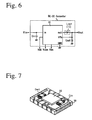
- Fig. 6 shows a step-down DC-DC converter comprising an input capacitor Cin, an output capacitor Cout, an output inductor Lout, and an integrated circuit semiconductor IC including a switching device and a control circuit as discrete circuits on a printed circuit board.
- Ton Ton
- Toff a time period in which the switching device is turned off
- An LC circuit comprising an output inductor Lout storing and discharging current energy, and an output capacitor Cout storing and discharging voltage energy acts as a filter circuit (smoothing circuit) for outputting DC voltage.
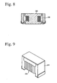
- An output inductor Lout widely used at present comprises a conductor wire 230 wound around a magnetic core 220.
- Used for the magnetic core 220 is high-resistance ferrite such as Ni-Zn ferrite, Ni-Cu-Zn ferrite, etc., so that a conductor wire can be wound directly around it.
- JP 2002-289421 A discloses Ni-Cu-Zn ferrite comprising 46-50% by mol of Fe 2 O 3 , 2-13% by mol of CuO, 24-30.5% by mol of ZnO, and 3.5% by mol or less of Mn 2 O 3 , the balance being NiO, which has a high saturation magnetic flux density and low loss.
- Mn 2 O 3 provides this ferrite with reduced loss at a magnetic flux density of 150 mT and a frequency of 50 kHz.
- this reference does not propose any measures to achieve loss reduction at high frequencies, and to cope with the deterioration of characteristics under stress and the change of characteristics with temperature.
- Inductors are also required to have stability under stress (little variation of inductance and less increase in loss under stress).
- stress includes stress caused by the difference in a linear thermal expansion coefficient between an inductor and a printed circuit board, stress caused by the deformation of a printed circuit board, stress caused by the curing of a molding resin when an inductor is sealed with a resin, stress caused by shrinkage difference when internal conductors and ferrite are simultaneously sintered to produce a laminated inductor, stress caused by plating external terminals, etc.
- DC/DC converters are exposed to heat generated by integrated circuit semiconductors IC, etc., inductors used therein are required to exhibit stable characteristics at use temperatures; little variation of inductance with temperature.
- JP 05-326243 A discloses Ni-Cu-Zn ferrite comprising 100% by mass of main components comprising 46.5-49.5% by mol of Fe 2 O 3 , 5.0-12.0% by mol of CuO, and 2.0-30.0% by mol of ZnO, the balance being NiO, and sub-components comprising 0.05-0.6% by mass of Co 3 O 4 , 0.5-2% by mass of Bi 2 O 3 , and 0.1-2% by mass in total of SiO 2 and SnO 2 .
- this Ni-Cu-Zn ferrite does not contain Mn (Mn 2 O 3 ) though it contains SnO 2 .
- an object of the present invention is to provide a low-loss ferrite sinterable at lower temperatures than the melting point of Ag, having low loss at high frequencies of 2 MHz or more, and suffering little variation of characteristics in a wide temperature range even under stress, and an electronic device using such low-loss ferrite.
- the low-loss ferrite of the present invention comprises as main components 47.1-49.3% by mol of Fe 2 O 3 , 20-26% by mol of ZnO, and 6-14% by mol of CuO, the balance being NiO, and 0.1-2% by mass (as SnO 2 ) of Sn and 0.05-2% by mass (as Mn 3 O 4 ) of Mn based on 100% by mass of the main components, and having an average crystal grain size of 0.5-3 ⁇ m.
- the low-loss ferrite of the present invention preferably has core loss of 2700 kW/m 3 or less at a frequency of 2 MHz and at an operating magnetic flux density Bm of 33 mT, and 430 kW/m 3 or less at a frequency of 5 MHz and at an operating magnetic flux density Bm of 10 mT, and saturation magnetic flux density Bs of 390 mT or more in a magnetic field of 4000 A/m.
- the first electronic device of the present invention comprises a magnetic core made of the above low-loss ferrite, and at least one coil wound around the magnetic core.
- the second electronic device of the present invention comprises an integrally sintered laminate comprising pluralities of ferrite layers made of the above low-loss ferrite, and at least one coil formed by Ag-containing electrodes in the laminate.
- a semiconductor device including at least one switch device, at least one capacitor and at least one resistance device preferably are mounted, at least the semiconductor device being mounted on an electrode on the surface of the laminate.
- Fig. 1 is a perspective view showing a laminated inductor using the low-loss ferrite of the present invention.
- Fig. 2 is a graph showing the change ratio of inductance under stress in low-loss ferrite samples having different Sn contents.
- Fig. 3 is a graph showing the change ratio of core loss under stress in low-loss ferrite samples having different Sn contents.
- Fig. 4 is a graph showing the change ratio of inductance under stress in low-loss ferrite samples having different Mn contents.
- Fig. 5 is a graph showing the change ratio of core loss under stress in low-loss ferrite samples having different Mn contents.
- Fig. 6 is a view showing an equivalent circuit of a DC/DC converter.
- Fig. 7 is a perspective view showing a DC/DC converter using the low-loss ferrite of the present invention.
- Fig. 8 is a cross-sectional view showing one example of inductors comprising a ferrite magnetic core.
- Fig. 9 is a perspective view showing the inductor of Fig. 8 .
- the low-loss ferrite of the present invention (Ni-Cu-Zn ferrite) comprises as main components 47.1-49.3% by mol of Fe 2 O 3 , 20-26% by mol of ZnO, and 6-14% by mol of CuO, the balance being NiO.
- Fe 2 O 3 When Fe 2 O 3 is less than 47.1 % by mol, the ferrite has large core loss Pcv at 2 MHz and 5 MHz, and does not have sufficient permeability. When Fe 2 O 3 is more than 49.3% by mol, the ferrite is not sufficiently sintered at a temperature equal to or lower than 960°C, the melting point of Ag, and has poor magnetic properties and low mechanical strength. Fe 2 O 3 is preferably 47.5-49.0% by mol.
- the ferrite When ZnO is less than 20% by mol, the ferrite has large core loss at a frequency of 2 MHz and an operating magnetic flux density of 33 mT, and low permeability. When ZnO is more than 26% by mol, the ferrite has large core loss at a frequency of 5 MHz and an operating magnetic flux density of 10 mT. ZnO is preferably 21-26% by mol.
- the ferrite When CuO is less than 6% by mol or more than 14% by mol, the ferrite has a low saturation magnetic flux density Bs of less than 390 mT. Decrease in the saturation magnetic flux density Bs undesirably results in the deterioration of DC superimposition characteristics.
- CuO contributing to lowering sintering temperatures is less than 6% by mol, the ferrite is likely to have an insufficient sintering density.
- CuO is preferably 7-11% by mol.
- NiO is the balance of main components.
- a molar ratio of NiO/CuO is preferably 1.0-3.1.
- the low-loss ferrite of the present invention comprises 0.1-2% by mass (as SnO 2 ) of Sn, and 0.05-2% by mass (as Mn 3 O 4 ) of Mn as sub-components, per 100% by mass of the main components.
- Sn provides the ferrite with decreased saturation magnetic flux density Bs and increased coercivity Hc.
- Sn is dissolved in crystal grains as stable tetravalent ions to reduce lattice strain, thereby reducing a saturation magnetostriction constant ⁇ s and a magnetic anisotropy constant K1, and thus suppressing inductance change and core loss increase due to stress.
- the saturation magnetic flux density Bs and the magnetic anisotropy constant K1 decrease, but the addition of 2% by mass or less (as SnO 2 ) of Sn makes it possible to adjust the saturation magnetic flux density Bs and the magnetic anisotropy constant K1 at use temperatures, thereby reducing the change of initial permeability ⁇ i with temperatures.
- SnO 2 When SnO 2 is more than 2% by mass, part of it enters grain boundaries to hinder sintering, so that the sintering density does not increase at 960°C or lower, resulting in deteriorated magnetic properties such as permeability, etc. It is thus undesirable for a laminate device integrally sintered with Ag electrodes, etc. When SnO 2 is less than 0.05% by mass, sufficient effect of adding SnO 2 cannot be obtained. The preferred amount of Sn is 0.25-2% by mass as SnO 2 .
- the low-loss ferrite of the present invention contains 0.05-2% by mass (as Mn 3 O 4 ) of Mn.
- Mn reduces lattice strain, increases initial permeability ⁇ i, improves the linearity of a BH loop, and reduces coercivity Hc in a minor loop and hysteresis loss.
- Mn suppresses the movement of electrons between Fe 3+ and Fe 2+ , it increases resistivity p and reduces eddy current loss.
- the addition of Mn 3 O 4 tends to deteriorate the stress characteristics of core loss Pcv and inductance. Accordingly, the amount of Mn 3 O 4 is preferably 0.1-1.5% by mass.
- the low-loss ferrite of the present invention may further contain 1.5% by mass or less (as CaO) of Ca, and 1.5% by mass or less (as SiO 2 ) of Si. They suppress the growth of crystal grains, resulting in decreased permeability and increased resistivity. To alleviate the reduction of sinterability by the addition of Sn, 0.3% by mass or less (as Bi 2 O 3 ) of Bi may be added.
- the amounts of inevitable impurities contained in the ferrite-forming materials are preferably as small as possible, and their industrially permitted ranges are 0.05% by mass or less in total. Particularly less than 5 ppm of Cl and less than 8 ppm of P are advantageous for low loss.
- the amounts of the main components and the sub-components are determined by fluorescent X-ray analysis and ICP atomic emission spectroscopy. Elements contained are first qualitatively analyzed by fluorescent X-ray, and then quantitatively analyzed by a calibration method comparing with a standard sample.
- the low-loss ferrite of the present invention has an average crystal grain size of 0.5-3 ⁇ m.
- the average crystal grain size of 3 ⁇ m or less reduces eddy current loss, residual loss because of decrease in magnetic domain walls, and core loss at high frequencies.
- grain boundaries act as pinning points of magnetic domain walls, resulting in decrease in permeability and increase in core loss.
- the average crystal grain size is more than 3 ⁇ m, the eddy current loss and the residual loss have large influence, resulting in remarkable increase in loss at high frequencies (for instance, 5 MHz).
- the calcined ferrite powder to be sintered preferably has a BET specific surface area of 5-10 m 2 /g. Because a larger BET specific surface area provides larger reactivity, densification is accelerated from low sintering temperatures.
- the BET specific surface area of the calcined ferrite powder is 5-10 m 2 /g, dense ferrite having a small and uniform crystal grain size is obtained even at as low sintering temperatures as 960°C or lower.
- the sintered ferrite may have an average crystal grain size of more than 3 ⁇ m.
- the BET specific surface area is more than 10 m 2 /g, the calcined ferrite powder easily aggregates and adsorbs water, so that calcined ferrite powder slurry containing a water-soluble resin such as polyvinyl butyral as a binder easily has an aggregated structure, providing green sheets with a lot of pores, which serve as paths for water to intrude into the electronic device.
- the preferred BET specific surface area of the calcined ferrite powder is 5.5-8 m 2 /g.
- the initial permeability ⁇ i of ferrite is parallel to Bs 2 /(aK1 + b ⁇ s ⁇ ), wherein Bs represents a saturation magnetic flux density, K1 represents a magnetic anisotropy constant, ⁇ s represents a magnetostriction constant, ⁇ represents stress, and a and b represent constants. Because Ni-Cu-Zn ferrite has a negative magnetostriction constant, the initial permeability ⁇ i increases to the maximum and then decreases with compression stress. When an inductor is provided with a magnetic gap in its magnetic circuit to improve its DC superimposition characteristics, its effective permeability is reduced. Accordingly, the permeability of the ferrite is preferably 150 or more.
- Fig. 1 shows a laminated inductor containing a coil (inductor), as an electronic device using the low-loss ferrite of the present invention.
- This laminated inductor 10 can be produced by forming green sheets of low-loss ferrite by a doctor blade method, etc., forming a coil pattern 3 on each sheet with a conductor paste of Ag or its alloy, etc., further printing a ferrite paste and a non-magnetic paste, if necessary, laminating the green sheets, integrally sintering them, and forming external terminals 200a, 200b on the side surfaces of a laminate 2 on which the conductor patterns are exposed.
- Fig. 7 shows a DC/DC converter module comprising an integrated-circuit semiconductor IC and capacitors Cin, Cout mounted on the surface electrodes of an inductor-containing laminate substrate 10 to have electric connection to the inductor.
- an inductor and an integrated-circuit semiconductor IC may be mounted on a capacitor-containing laminate substrate to constitute a module.
- various modifications may, of course, be added unless they deviate from the scope of the present invention.
- the main components of Fe 2 O 3 , ZnO, CuO and NiO, and the sub-components of SnO 2 and Mn 3 O 4 were wet-mixed at proportions shown in Tables 1 and 2, dried, and then calcined at 800°C for 2 hours.
- the resultant the calcined powder was charged into a ball mill together with ion-exchanged water, and pulverized for about 20 hours until its BET specific surface area became 6.5 m 2 /g.
- Each calcined powder was mixed with polyvinyl alcohol, granulated by a spray-drying method, molded, and sintered at a temperature in a range of 875-950°C shown in Tables 1 and 2 for 2 hours in the air, to obtain ring samples of 8 mm in outer diameter, 4 mm in inner diameter and 2 mm in thickness, and squarely annular samples of 8 mm x 8 mm in outer size, 4 mm x 4 mm in inner size, and 2 mm in thickness.
- the density, average crystal grain size, initial permeability ⁇ i, saturation magnetic flux density Bs, residual magnetic flux density Br, coercivity Hc, resistivity, core loss Pcv, and relative temperature coefficient ⁇ ir of initial permeability ⁇ i of each sample were measured by the following methods. The measurement results are shown in Tables 3 and 4.
- the density was calculated from the size and weight of a ring sample.
- a straight line having an arbitrary length L 1 was drawn on an electron photomicrograph (magnification: 10,000 times) of a ring sample to count the number N 1 of particles existing on this straight line, and the length L 1 was divided by the number of N 1 particles to calculate L 1 /N 1 .
- the values of L 1 /N 1 obtained on pluralities of straight lines were averaged to determine the average crystal grain size.
- Initial permeability ⁇ i was measured with respect to each sample adjusted to -40°C to + 80°C in an electronic constant-temperature chamber.
- T 1 + 20°C
- T 2 -40°C
- ⁇ i 1 initial permeability at + 20°C
- ⁇ i 2 initial permeability at -40°C.
- T 1 + 20°C
- T 2 + 80°C
- ⁇ i 1 initial permeability at + 20°C
- ⁇ i 2 represents initial permeability at + 80°C.
- a major loop of the hysteresis of each ring sample was measured by a B-H analyzer in a magnetic field of 4000 A/m and a frequency of 10 kHz.
- the saturation magnetic flux density Bs was determined from this hysteresis loop.
- the residual magnetic flux density Br was determined from the above hysteresis loop.
- the coercivity Hc was determined from the above hysteresis loop.
- the ring sample was cut to half to obtain a test piece, whose cut surface was coated with a conductive resin and dried, and the resistivity of the test piece was measured by an insulation resistance meter at DC voltage of 50 V.
- Copper wires were wound around a ring sample by 7 turns on both primary and secondary sides, to measure Pcv at room temperature (25°C) under the conditions of 100 kHz and 50 mT, 2 MHz and 33 mT, and 5 MHz and 10 mT, respectively.
- Sample 1 comprising 47% by mol of Fe 2 O 3 had large coercivity Hc and core loss Pcv, and Sample 10 comprising 49.5% by mol of Fe 2 O 3 had a low sintering density and extremely large core loss Pcv, extremely poor magnetic properties.
- Sample 11 containing no sub-component had large core loss Pcv at high frequencies.
- Sample 12 containing Bi 2 O 3 in place of the sub-component had a large average crystal grain size, and extremely poor core loss Pcv.
- Samples 5 and 6 containing 0.5% by mass of Bi 2 O 3 together with Sn and Mn were in an abnormally sintered state having a crystal structure comprising both crystal grains of about 30 ⁇ m and crystal grains of about 1 ⁇ m in particle size, and had extremely poor core loss Pcv at 5 MHz.
- Sample 36 containing no Sn had large core loss Pcv, and Sample 40 containing 3.0% by mass of Sn suffered insufficient sintering, having extremely poor magnetic properties and large core loss.
- Increase in the amount of SnO reduced the relative temperature coefficient ⁇ ir, and when the amount of SnO exceeded 1% by mass, the relative temperature coefficient ⁇ ir became negative. It is thus clear that a proper amount of SnO reduces the change of inductance with temperature.
- the addition of Mn reduced core loss Pcv, and increased resistivity.
- the relative temperature coefficient ⁇ ir increased along with the amount of Mn added, contrary to the addition of Sn.
- a copper wire was wound by 12 turns around each of rectangularly annular Samples 2, 13, 36, 37, 39, 44, 47 and 48, and each Sample was attached to a pressure jig equipped with a tensiometer.
- a compression force was applied to each Sample in one direction at room temperature, to continuously measure inductance at a frequency of 1 MHz and current of 1 mA, and core loss at a frequency of 2 MHz and an operating magnetic flux density Bm of 33 mT.
- the change ratios of inductance and core loss were calculated from them by the following formulae, to evaluate the stability of each Sample under stress. The results are shown in Figs. 2-5 .
- Fig. 2 shows the stability of inductance under stress
- Fig. 3 shows the stability of core loss under stress. As the amount of Sn increased, the change ratios of inductance and core loss under stress decreased.
- Fig. 4 shows the stability of inductance under stress
- Fig. 5 shows the stability of core loss under stress.
- the change ratios of inductance and core loss under stress increased.
- Sample 48 containing 2.1 % by mass of Mn 2 O 3 had poorer stability under stress than those containing no Sn.
- Each ferrite powder of Samples 2, 13 was pulverized together with a binder comprising polyvinyl butyral as a main component and ethanol in a ball mill, and the resultant slurry was applied onto a polyester film by a doctor blade method after the adjustment of viscosity, to form green sheets having dry thickness of 30 ⁇ m.
- Each ferrite green sheet was printed with an Ag paste to form pluralities of conductor coil patterns. If necessary, the green sheet was further printed with a ferrite paste and a non-magnetic paste.
- Pluralities of green sheets having conductor patterns were pressure-bonded, and the resultant laminate was cut to a post-sintering size of 3.2 mm x 1.6 mm x 1.0 mm, deprived of the binder, and then sintered at 900°C for 3 hours in the air.
- Conductor-pattern-exposing side surfaces of the laminate were printed with an Ag paste, and baked at 600°C to from external terminals 200a, 200b.
- a laminated inductor 10 containing a coil 3 in the laminate 2 was produced.
- Fig. 1 shows its appearance.
- the laminated inductor 10 was assembled in a step-down DC/DC converter shown in Fig. 6 , which had a switching frequency fs of 2 MHz, input voltage Vin of 3.6 V, and output voltage Vout of 1.5 V, to measure DC/DC conversion efficiency.
- Sample 2 was about 1% higher than Sample 13 in conversion efficiency. Sample 2 has high DC/DC conversion efficiency, presumably because it has low loss and an extremely small change ratio of Pcv under stress.
- the low-loss ferrite of the present invention is sinterable at a temperature equal to or lower than 960°C, the melting point of Ag, has low loss at high frequencies of 2 MHz or more, and suffers little variation of characteristics in a wide temperature range even in an environment in which stress and large superimposed DC current are applied. Accordingly, the low-loss ferrite of the present invention is suitable for electronic devices such as laminated inductors, coil-containing laminate substrates, etc.
Landscapes
- Engineering & Computer Science (AREA)
- Chemical & Material Sciences (AREA)
- Ceramic Engineering (AREA)
- Manufacturing & Machinery (AREA)
- Power Engineering (AREA)
- Materials Engineering (AREA)
- Structural Engineering (AREA)
- Organic Chemistry (AREA)
- Inorganic Chemistry (AREA)
- Dispersion Chemistry (AREA)
- Physics & Mathematics (AREA)
- Thermal Sciences (AREA)
- Microelectronics & Electronic Packaging (AREA)
- Magnetic Ceramics (AREA)
- Soft Magnetic Materials (AREA)
- Coils Or Transformers For Communication (AREA)
- Inorganic Compounds Of Heavy Metals (AREA)
Abstract
Description
- The present invention relates to low-temperature-sinterable, low-loss ferrite with little variation of characteristics in a wide temperature range even under stress, and an electronic device having inductors formed by such ferrite.
- Various mobile electronic gears (cell phones, mobile information terminals PDA, note-type personal computers, DVD players, CD players, MD players, digital cameras, digital video cameras, etc.) comprise pluralities of DC/DC converters as power conversion apparatuses for converting the voltage of contained cells to operation voltage. In note-type personal computers, for instance, DC/DC converters are arranged near digital signal processors (DSP), micro processing units (MPU), etc.
- As one example of DC/DC converters,
Fig. 6 shows a step-down DC-DC converter comprising an input capacitor Cin, an output capacitor Cout, an output inductor Lout, and an integrated circuit semiconductor IC including a switching device and a control circuit as discrete circuits on a printed circuit board. By operating the switching device based on a control signal from the control circuit, output voltage Vout expressed by Vout = Ton/(Ton + Toff) x Vin, wherein Ton is a time period in which the switching device is turned on, and Toff is a time period in which the switching device is turned off, is obtained from DC input voltage Vin. Even with the variation of the input voltage Vin, stable output voltage Vout can be obtained by adjusting a Ton/Toff ratio. An LC circuit comprising an output inductor Lout storing and discharging current energy, and an output capacitor Cout storing and discharging voltage energy acts as a filter circuit (smoothing circuit) for outputting DC voltage. - An output inductor Lout widely used at present, as shown in
Figs. 8 and 9 , comprises aconductor wire 230 wound around amagnetic core 220. Used for themagnetic core 220 is high-resistance ferrite such as Ni-Zn ferrite, Ni-Cu-Zn ferrite, etc., so that a conductor wire can be wound directly around it. - The reduction of the operation voltage of LSI (large scale integration) constituting DSP and MPU has recently been accelerated to expand the usable time period of cells. Operation voltage has been lowered to 2.5 V, and further to 1.8 V, for high-speed-operation parts such as MPU and DSP. Because of such decrease of operation voltage, the voltage margin of LSI is reduced relative to the variation (ripple) of the output voltage of DC/DC converters, so that LSI is more influenced by noise. To cope with this, the switching frequencies of DC/DC converters have been increased from conventional 500 kHz to 1 MHz or more to suppress ripple.
- Higher switching frequencies reduce inductance required for an output inductor Lout, enabling the size reduction of the inductor and a power supply circuit. However, higher switching frequencies contribute to the reduction of conversion efficiency due to loss generated in switching devices and inductors. Although power loss by inductors is caused predominantly by the DC resistance of conductor lines and output current at low frequencies, AC resistance (AC resistance of conductor lines and core loss of ferrite) is not negligible at high frequencies. Accordingly, to operate DC/DC converters efficiently at high frequencies exceeding 1 MHz, the core loss of ferrite constituting inductors should be reduced. The core loss of ferrite is determined by hysteresis loss, eddy current loss and residual loss. It is known that these losses depend on the magnetic properties (coercivity, saturation magnetization, magnetic domain wall resonance, etc.), crystal grain size, resistivity, etc. of ferrite.
-
JP 2002-289421 A - Inductors are also required to have stability under stress (little variation of inductance and less increase in loss under stress). Such stress includes stress caused by the difference in a linear thermal expansion coefficient between an inductor and a printed circuit board, stress caused by the deformation of a printed circuit board, stress caused by the curing of a molding resin when an inductor is sealed with a resin, stress caused by shrinkage difference when internal conductors and ferrite are simultaneously sintered to produce a laminated inductor, stress caused by plating external terminals, etc. Also, because DC/DC converters are exposed to heat generated by integrated circuit semiconductors IC, etc., inductors used therein are required to exhibit stable characteristics at use temperatures; little variation of inductance with temperature.
- As ferrite having improved stability and temperature characteristics under stress,
JP 05-326243 A - Accordingly, an object of the present invention is to provide a low-loss ferrite sinterable at lower temperatures than the melting point of Ag, having low loss at high frequencies of 2 MHz or more, and suffering little variation of characteristics in a wide temperature range even under stress, and an electronic device using such low-loss ferrite.
- The low-loss ferrite of the present invention comprises as main components 47.1-49.3% by mol of Fe2O3, 20-26% by mol of ZnO, and 6-14% by mol of CuO, the balance being NiO, and 0.1-2% by mass (as SnO2) of Sn and 0.05-2% by mass (as Mn3O4) of Mn based on 100% by mass of the main components, and having an average crystal grain size of 0.5-3 µm.
- The low-loss ferrite of the present invention preferably has core loss of 2700 kW/m3 or less at a frequency of 2 MHz and at an operating magnetic flux density Bm of 33 mT, and 430 kW/m3 or less at a frequency of 5 MHz and at an operating magnetic flux density Bm of 10 mT, and saturation magnetic flux density Bs of 390 mT or more in a magnetic field of 4000 A/m.
- The first electronic device of the present invention comprises a magnetic core made of the above low-loss ferrite, and at least one coil wound around the magnetic core.
- The second electronic device of the present invention comprises an integrally sintered laminate comprising pluralities of ferrite layers made of the above low-loss ferrite, and at least one coil formed by Ag-containing electrodes in the laminate. In this electronic device, a semiconductor device including at least one switch device, at least one capacitor and at least one resistance device preferably are mounted, at least the semiconductor device being mounted on an electrode on the surface of the laminate.
-
Fig. 1 is a perspective view showing a laminated inductor using the low-loss ferrite of the present invention. -
Fig. 2 is a graph showing the change ratio of inductance under stress in low-loss ferrite samples having different Sn contents. -
Fig. 3 is a graph showing the change ratio of core loss under stress in low-loss ferrite samples having different Sn contents. -
Fig. 4 is a graph showing the change ratio of inductance under stress in low-loss ferrite samples having different Mn contents. -
Fig. 5 is a graph showing the change ratio of core loss under stress in low-loss ferrite samples having different Mn contents. -
Fig. 6 is a view showing an equivalent circuit of a DC/DC converter. -
Fig. 7 is a perspective view showing a DC/DC converter using the low-loss ferrite of the present invention. -
Fig. 8 is a cross-sectional view showing one example of inductors comprising a ferrite magnetic core. -
Fig. 9 is a perspective view showing the inductor ofFig. 8 . - [1] Low-loss ferrite
- (A) Composition
- (1) Main components
- The low-loss ferrite of the present invention (Ni-Cu-Zn ferrite) comprises as main components 47.1-49.3% by mol of Fe2O3, 20-26% by mol of ZnO, and 6-14% by mol of CuO, the balance being NiO.
- When Fe2O3 is less than 47.1 % by mol, the ferrite has large core loss Pcv at 2 MHz and 5 MHz, and does not have sufficient permeability. When Fe2O3 is more than 49.3% by mol, the ferrite is not sufficiently sintered at a temperature equal to or lower than 960°C, the melting point of Ag, and has poor magnetic properties and low mechanical strength. Fe2O3 is preferably 47.5-49.0% by mol.
- When ZnO is less than 20% by mol, the ferrite has large core loss at a frequency of 2 MHz and an operating magnetic flux density of 33 mT, and low permeability. When ZnO is more than 26% by mol, the ferrite has large core loss at a frequency of 5 MHz and an operating magnetic flux density of 10 mT. ZnO is preferably 21-26% by mol.
- When CuO is less than 6% by mol or more than 14% by mol, the ferrite has a low saturation magnetic flux density Bs of less than 390 mT. Decrease in the saturation magnetic flux density Bs undesirably results in the deterioration of DC superimposition characteristics. When CuO contributing to lowering sintering temperatures is less than 6% by mol, the ferrite is likely to have an insufficient sintering density. CuO is preferably 7-11% by mol.
- The amount of NiO is the balance of main components. To obtain the desired permeability and a high saturation magnetic flux density Bs, a molar ratio of NiO/CuO is preferably 1.0-3.1.
- (2) Sub-components
- The low-loss ferrite of the present invention comprises 0.1-2% by mass (as SnO2) of Sn, and 0.05-2% by mass (as Mn3O4) of Mn as sub-components, per 100% by mass of the main components.
- The addition of Sn provides the ferrite with decreased saturation magnetic flux density Bs and increased coercivity Hc. Sn is dissolved in crystal grains as stable tetravalent ions to reduce lattice strain, thereby reducing a saturation magnetostriction constant λs and a magnetic anisotropy constant K1, and thus suppressing inductance change and core loss increase due to stress.
As the temperature elevates, the saturation magnetic flux density Bs and the magnetic anisotropy constant K1 decrease, but the addition of 2% by mass or less (as SnO2) of Sn makes it possible to adjust the saturation magnetic flux density Bs and the magnetic anisotropy constant K1 at use temperatures, thereby reducing the change of initial permeability µi with temperatures. When SnO2 is more than 2% by mass, part of it enters grain boundaries to hinder sintering, so that the sintering density does not increase at 960°C or lower, resulting in deteriorated magnetic properties such as permeability, etc. It is thus undesirable for a laminate device integrally sintered with Ag electrodes, etc. When SnO2 is less than 0.05% by mass, sufficient effect of adding SnO2 cannot be obtained. The preferred amount of Sn is 0.25-2% by mass as SnO2. - The low-loss ferrite of the present invention contains 0.05-2% by mass (as Mn3O4) of Mn. The addition of Mn reduces lattice strain, increases initial permeability µi, improves the linearity of a BH loop, and reduces coercivity Hc in a minor loop and hysteresis loss. Because Mn suppresses the movement of electrons between Fe3+ and Fe2+, it increases resistivity p and reduces eddy current loss. However, the addition of Mn3O4 tends to deteriorate the stress characteristics of core loss Pcv and inductance. Accordingly, the amount of Mn3O4 is preferably 0.1-1.5% by mass.
- The valency of Mn added partially changes, obviating decrease in the initial permeability µi and increase in the coercivity Hc due to the addition of Sn. Accordingly, the addition of both Sn and Mn provides ferrite with excellent stability under stress and remarkably reduced loss.
- (3) Other components
- The low-loss ferrite of the present invention may further contain 1.5% by mass or less (as CaO) of Ca, and 1.5% by mass or less (as SiO2) of Si. They suppress the growth of crystal grains, resulting in decreased permeability and increased resistivity. To alleviate the reduction of sinterability by the addition of Sn, 0.3% by mass or less (as Bi2O3) of Bi may be added.
- The amounts of inevitable impurities contained in the ferrite-forming materials, such as Na, S, Cl, P, W, B, etc., are preferably as small as possible, and their industrially permitted ranges are 0.05% by mass or less in total. Particularly less than 5 ppm of Cl and less than 8 ppm of P are advantageous for low loss.
- The amounts of the main components and the sub-components are determined by fluorescent X-ray analysis and ICP atomic emission spectroscopy. Elements contained are first qualitatively analyzed by fluorescent X-ray, and then quantitatively analyzed by a calibration method comparing with a standard sample.
- (B) Structure and properties
- The low-loss ferrite of the present invention has an average crystal grain size of 0.5-3 µm. The average crystal grain size of 3 µm or less reduces eddy current loss, residual loss because of decrease in magnetic domain walls, and core loss at high frequencies. However, when the average crystal grain size is less than 0.5 µm, grain boundaries act as pinning points of magnetic domain walls, resulting in decrease in permeability and increase in core loss. When the average crystal grain size is more than 3 µm, the eddy current loss and the residual loss have large influence, resulting in remarkable increase in loss at high frequencies (for instance, 5 MHz).
- To obtain the average crystal grain size of 3 µm or less, the calcined ferrite powder to be sintered preferably has a BET specific surface area of 5-10 m2/g. Because a larger BET specific surface area provides larger reactivity, densification is accelerated from low sintering temperatures. When the BET specific surface area of the calcined ferrite powder is 5-10 m2/g, dense ferrite having a small and uniform crystal grain size is obtained even at as low sintering temperatures as 960°C or lower.
- When the BET specific surface area of the calcined ferrite powder is less than 5 m2/g, the sintered ferrite may have an average crystal grain size of more than 3 µm. When the BET specific surface area is more than 10 m2/g, the calcined ferrite powder easily aggregates and adsorbs water, so that calcined ferrite powder slurry containing a water-soluble resin such as polyvinyl butyral as a binder easily has an aggregated structure, providing green sheets with a lot of pores, which serve as paths for water to intrude into the electronic device. The preferred BET specific surface area of the calcined ferrite powder is 5.5-8 m2/g.
- The initial permeability µi of ferrite is parallel to Bs2/(aK1 + bλsσ), wherein Bs represents a saturation magnetic flux density, K1 represents a magnetic anisotropy constant, λs represents a magnetostriction constant, σ represents stress, and a and b represent constants. Because Ni-Cu-Zn ferrite has a negative magnetostriction constant, the initial permeability µi increases to the maximum and then decreases with compression stress. When an inductor is provided with a magnetic gap in its magnetic circuit to improve its DC superimposition characteristics, its effective permeability is reduced. Accordingly, the permeability of the ferrite is preferably 150 or more.
- [2] Electronic device
-
Fig. 1 shows a laminated inductor containing a coil (inductor), as an electronic device using the low-loss ferrite of the present invention. Thislaminated inductor 10 can be produced by forming green sheets of low-loss ferrite by a doctor blade method, etc., forming a coil pattern 3 on each sheet with a conductor paste of Ag or its alloy, etc., further printing a ferrite paste and a non-magnetic paste, if necessary, laminating the green sheets, integrally sintering them, and formingexternal terminals laminate 2 on which the conductor patterns are exposed. - As another example of the electronic devices,
Fig. 7 shows a DC/DC converter module comprising an integrated-circuit semiconductor IC and capacitors Cin, Cout mounted on the surface electrodes of an inductor-containinglaminate substrate 10 to have electric connection to the inductor. Alternatively, an inductor and an integrated-circuit semiconductor IC may be mounted on a capacitor-containing laminate substrate to constitute a module. Apart from them, various modifications may, of course, be added unless they deviate from the scope of the present invention. - The present invention will be explained in further detail by Examples below without intention of restricting the present invention thereto.
- Example 1
- The main components of Fe2O3, ZnO, CuO and NiO, and the sub-components of SnO2 and Mn3O4 were wet-mixed at proportions shown in Tables 1 and 2, dried, and then calcined at 800°C for 2 hours. The resultant the calcined powder was charged into a ball mill together with ion-exchanged water, and pulverized for about 20 hours until its BET specific surface area became 6.5 m2/g. Each calcined powder was mixed with polyvinyl alcohol, granulated by a spray-drying method, molded, and sintered at a temperature in a range of 875-950°C shown in Tables 1 and 2 for 2 hours in the air, to obtain ring samples of 8 mm in outer diameter, 4 mm in inner diameter and 2 mm in thickness, and squarely annular samples of 8 mm x 8 mm in outer size, 4 mm x 4 mm in inner size, and 2 mm in thickness.
-
Table 1 No. Main Components (mol %) Sub-Components (% by mass) Sintering Temperature (°C) Fe2O3 ZnO NiO CuO SnO2 Mn3O4 Bi2O3 *1 47.0 23.9 20.3 8.8 0.50 0.10 - 900 2 47.5 23.9 19.8 8.8 0.50 0.10 - 900 3 47.5 23.9 19.8 8.8 0.50 0.10 0.25 875 4 47.5 23.9 19.8 8.8 0.50 0.10 0.25 900 *5 47.5 23.9 19.8 8.8 0.50 0.10 0.5 875 *6 47.5 23.9 19.8 8.8 0.50 0.10 0.5 900 7 48.0 23.9 19.3 8.8 0.50 0.10 - 900 8 48.5 23.9 18.8 8.8 0.50 0.10 - 900 9 49.0 23.9 18.3 8.8 0.50 0.10 - 900 *10 49.5 23.9 17.8 8.8 0.50 0.10 - 900 *11 48.0 21.0 18.0 13.0 - - - 900 *12 47.5 23.9 19.8 8.8 - - 0.5 900 *13 49.0 21.0 17.0 13.0 - 0.10 - 900 *14 48.5 19.0 23.7 8.8 0.50 0.10 - 900 15 48.5 21.0 21.7 8.8 0.50 0.10 - 900 16 48.5 22.0 20.7 8.8 0.50 0.10 - 900 17 48.5 23.0 19.7 8.8 0.50 0.10 - 900 18 48.5 23.9 18.8 8.8 0.50 0.10 - 900 19 48.5 25.0 17.7 8.8 0.50 0.10 - 900 20 48.5 25.0 17.7 8.8 0.50 0.10 0.3 875 21 48.5 26.0 16.7 8.8 0.50 0.10 - 900 *22 48.5 28.0 14.7 8.8 0.50 0.10 - 900 *23 48.5 29.0 11.5 11.0 0.50 0.10 - 900 *24 48.5 30.0 12.5 9.0 0.50 0.10 - 900 *25 48.5 31.0 11.7 8.8 0.50 0.10 - 900 -
Table 2 No. Main Components (mol %) Sub-Components (% by mass) Sintering Temperature (°C) Fe2O3 ZnO NiO CuO SnO2 Mn3O4 Bi2O3 26 48.7 25.0 17.5 8.8 0.50 0.10 - 900 27 48.9 25.0 17.3 8.8 0.50 0.10 - 900 28 49.3 25.0 16.9 8.8 0.50 0.10 - 950 *29 49.5 25.0 16.7 8.8 0.50 0.10 - 950 *30 47.5 23.9 23.6 5.0 0.50 0.10 - 900 31 47.5 23.9 21.6 7.0 0.50 0.10 - 900 32 47.5 23.9 19.6 9.0 0.50 0.10 - 900 33 47.5 23.9 17.6 11.0 0.50 0.10 - 900 34 47.5 23.9 15.6 13.0 0.50 0.10 - 900 *35 47.5 23.9 13.6 15.0 0.50 0.10 - 900 *36 47.5 23.9 19.8 8.8 - 0.10 - 900 37 47.5 23.9 19.8 8.8 0.25 0.10 - 900 38 47.5 23.9 19.8 8.8 0.75 0.10 - 900 39 47.5 23.9 19.8 8.8 1.00 0.10 - 900 *40 47.5 23.9 19.8 8.8 3.00 0.10 - 900 *41 47.5 23.9 19.8 8.8 0.50 - - 900 42 47.5 23.9 19.8 8.8 0.50 0.35 - 900 43 47.5 23.9 19.8 8.8 0.50 0.60 - 875 44 47.5 23.9 19.8 8.8 0.50 0.60 - 900 45 47.5 23.9 19.8 8.8 0.50 0.60 - 925 46 47.5 23.9 19.8 8.8 0.50 0.85 - 900 47 47.5 23.9 19.8 8.8 0.50 1.10 - 900 *48 47.5 23.9 19.8 8.8 0.50 2.10 - 900 Note: * Samples outside the scope of the present invention. - The density, average crystal grain size, initial permeability µi, saturation magnetic flux density Bs, residual magnetic flux density Br, coercivity Hc, resistivity, core loss Pcv, and relative temperature coefficient αµir of initial permeability µi of each sample were measured by the following methods. The measurement results are shown in Tables 3 and 4.
- (1) Density
- The density was calculated from the size and weight of a ring sample.
- (2) Average crystal grain size
- A straight line having an arbitrary length L1 was drawn on an electron photomicrograph (magnification: 10,000 times) of a ring sample to count the number N1 of particles existing on this straight line, and the length L1 was divided by the number of N1 particles to calculate L1/N1. The values of L1/N1 obtained on pluralities of straight lines were averaged to determine the average crystal grain size.
- (3) Initial permeability µi
- A copper wire was wound around a ring sample by 7 turns to produce an inductor, whose inductance L was measured by an LCR meter at a frequency of 1 MHz and current of 1 mA, to calculate initial permeability µi by the following formula:

wherein le represents the length of a magnetic path, L represents inductance, µ0 represents the permeability of vacuum, which is 4π x 10-7 (H/m), Ae represents the cross section area of a sample, and N represents the number of turns of a coil. - (4) Relative temperature coefficient αµir of initial permeability µi
- The relative temperature coefficient αµir of initial permeability µi is expressed by the following formula:

wherein T1 and T2 represent measurement temperatures, µi1 represents initial permeability at the temperature T1, and µi2 represents initial permeability at the temperature T2. - Initial permeability µi was measured with respect to each sample adjusted to -40°C to + 80°C in an electronic constant-temperature chamber. In the case of a relative temperature coefficient αµir from -40°C to + 20°C, T1 = + 20°C, and T2 = -40°C, µi1 represents initial permeability at + 20°C, and µi2 represents initial permeability at -40°C. In the case of relative temperature coefficient αµir from + 20°C to + 80°C, T1 = + 20°C, T2 = + 80°C, µi1 represents initial permeability at + 20°C, and µi2 represents initial permeability at + 80°C.
- (5) Saturation magnetic flux density Bs
- A major loop of the hysteresis of each ring sample was measured by a B-H analyzer in a magnetic field of 4000 A/m and a frequency of 10 kHz.
The saturation magnetic flux density Bs was determined from this hysteresis loop. - (6) Residual magnetic flux density Br
- The residual magnetic flux density Br was determined from the above hysteresis loop.
- (7) Coercivity Hc
- The coercivity Hc was determined from the above hysteresis loop.
- (8) Resistivity
- The ring sample was cut to half to obtain a test piece, whose cut surface was coated with a conductive resin and dried, and the resistivity of the test piece was measured by an insulation resistance meter at DC voltage of 50 V.
- (9) Core loss Pcv
- Copper wires were wound around a ring sample by 7 turns on both primary and secondary sides, to measure Pcv at room temperature (25°C) under the conditions of 100 kHz and 50 mT, 2 MHz and 33 mT, and 5 MHz and 10 mT, respectively.
-


-


- Sample 1 comprising 47% by mol of Fe2O3 had large coercivity Hc and core loss Pcv, and
Sample 10 comprising 49.5% by mol of Fe2O3 had a low sintering density and extremely large core loss Pcv, extremely poor magnetic properties. Sample 11 containing no sub-component had large core loss Pcv at high frequencies. Sample 12 containing Bi2O3 in place of the sub-component had a large average crystal grain size, and extremely poor core loss Pcv.Samples 5 and 6 containing 0.5% by mass of Bi2O3 together with Sn and Mn were in an abnormally sintered state having a crystal structure comprising both crystal grains of about 30 µm and crystal grains of about 1 µm in particle size, and had extremely poor core loss Pcv at 5 MHz. - When the amount of ZnO increased while the amount of NiO decreased, the saturation magnetic flux density Bs, the residual magnetic flux density Br and the coercivity Hc decreased, while the initial permeability µi increased. At 2 MHz, increase in ZnO resulted in decrease in core loss Pcv, but at 5 MHz, Sample 17 containing 23% by mol of ZnO had small core loss Pcv, which increased regardless of whether the amount of ZnO increased or decreased.
- The substitution of part of Ni with a small amount of Cu provided poor sinterability, decreased initial permeability µi and saturation magnetic flux density Bs, and increased coercivity Hc and core loss Pcv. Alternatively, a large amount of Cu provided a low saturation magnetic flux density Bs.
- Sample 36 containing no Sn had large core loss Pcv, and
Sample 40 containing 3.0% by mass of Sn suffered insufficient sintering, having extremely poor magnetic properties and large core loss. Increase in the amount of SnO reduced the relative temperature coefficient αµir, and when the amount of SnO exceeded 1% by mass, the relative temperature coefficient αµir became negative. It is thus clear that a proper amount of SnO reduces the change of inductance with temperature. The addition of Mn reduced core loss Pcv, and increased resistivity. The relative temperature coefficient αµir increased along with the amount of Mn added, contrary to the addition of Sn. - A copper wire was wound by 12 turns around each of rectangularly
annular Samples Figs. 2-5 . - (1) Change ratio of inductance

wherein L1 represents inductance when compressed in one direction, and L0 represents inductance when not compressed in one direction. - (2) Change ratio of core loss

wherein Pcv1 represents core loss at 2 MHz and 33 mT when compressed in one direction, and Pcv0 represents core loss at 2 MHz and 33 mT when not compressed in one direction. - With respect to
Samples 2, 13, 36, 37 and 39 containing different amounts of Sn,Fig. 2 shows the stability of inductance under stress, andFig. 3 shows the stability of core loss under stress. As the amount of Sn increased, the change ratios of inductance and core loss under stress decreased. - With respect to
Samples Fig. 4 shows the stability of inductance under stress, andFig. 5 shows the stability of core loss under stress. As the amount of Mn increased, the change ratios of inductance and core loss under stress increased.Sample 48 containing 2.1 % by mass of Mn2O3 had poorer stability under stress than those containing no Sn. - Example 2
- Each ferrite powder of
Samples 2, 13 was pulverized together with a binder comprising polyvinyl butyral as a main component and ethanol in a ball mill, and the resultant slurry was applied onto a polyester film by a doctor blade method after the adjustment of viscosity, to form green sheets having dry thickness of 30 µm. Each ferrite green sheet was printed with an Ag paste to form pluralities of conductor coil patterns. If necessary, the green sheet was further printed with a ferrite paste and a non-magnetic paste. Pluralities of green sheets having conductor patterns were pressure-bonded, and the resultant laminate was cut to a post-sintering size of 3.2 mm x 1.6 mm x 1.0 mm, deprived of the binder, and then sintered at 900°C for 3 hours in the air. Conductor-pattern-exposing side surfaces of the laminate were printed with an Ag paste, and baked at 600°C to fromexternal terminals laminated inductor 10 containing a coil 3 in thelaminate 2 was produced.Fig. 1 shows its appearance. - The
laminated inductor 10 was assembled in a step-down DC/DC converter shown inFig. 6 , which had a switching frequency fs of 2 MHz, input voltage Vin of 3.6 V, and output voltage Vout of 1.5 V, to measure DC/DC conversion efficiency.Sample 2 was about 1% higher than Sample 13 in conversion efficiency.Sample 2 has high DC/DC conversion efficiency, presumably because it has low loss and an extremely small change ratio of Pcv under stress. - The low-loss ferrite of the present invention is sinterable at a temperature equal to or lower than 960°C, the melting point of Ag, has low loss at high frequencies of 2 MHz or more, and suffers little variation of characteristics in a wide temperature range even in an environment in which stress and large superimposed DC current are applied. Accordingly, the low-loss ferrite of the present invention is suitable for electronic devices such as laminated inductors, coil-containing laminate substrates, etc.
Claims (5)
- Low-loss ferrite comprising as main components 47.1-49.3% by mol of Fe2O3, 20-26% by mol of ZnO, and 6-14% by mol of CuO, the balance being NiO, and 0.1-2% by mass (as SnO2) of Sn and 0.05-2% by mass (as Mn3O4) of Mn based on 100% by mass of said main components, and having an average crystal grain size of 0.5-3 µm.
- The low-loss ferrite according to claim 1, which has core loss of 2700 kW/m3 or less at a frequency of 2 MHz and at an operating magnetic flux density Bm of 33 mT, and 430 kW/m3 or less at a frequency of 5 MHz and at an operating magnetic flux density Bm of 10 mT, and saturation magnetic flux density of 390 mT or more in a magnetic field of 4000 A/m.
- An electronic device comprising a magnetic core made of the low-loss ferrite recited in claim 1 or 2, and at least one coil wound around said magnetic core.
- An electronic device comprising an integrally sintered laminate comprising pluralities of ferrite layers made of the low-loss ferrite recited in claim 1 or 2, and at least one coil formed by Ag-containing electrodes in said laminate.
- The electronic device according to claim 4, on which a semiconductor device including at least one switch device, at least one capacitor and at least one resistor are mounted, at least said semiconductor device being mounted on an electrode on the surface of said laminate.
Applications Claiming Priority (2)
| Application Number | Priority Date | Filing Date | Title |
|---|---|---|---|
| JP2007027727 | 2007-02-07 | ||
| PCT/JP2008/051968 WO2008096795A1 (en) | 2007-02-07 | 2008-02-06 | Low-loss ferrite and electronic component using the same |
Publications (3)
| Publication Number | Publication Date |
|---|---|
| EP2112126A1 true EP2112126A1 (en) | 2009-10-28 |
| EP2112126A4 EP2112126A4 (en) | 2011-11-30 |
| EP2112126B1 EP2112126B1 (en) | 2013-10-16 |
Family
ID=39681701
Family Applications (1)
| Application Number | Title | Priority Date | Filing Date |
|---|---|---|---|
| EP08710864.3A Active EP2112126B1 (en) | 2007-02-07 | 2008-02-06 | Low-loss ferrite and electronic component using the same |
Country Status (6)
| Country | Link |
|---|---|
| US (1) | US8237529B2 (en) |
| EP (1) | EP2112126B1 (en) |
| JP (3) | JP4914448B2 (en) |
| KR (1) | KR101429207B1 (en) |
| CN (1) | CN101668719B (en) |
| WO (1) | WO2008096795A1 (en) |
Cited By (1)
| Publication number | Priority date | Publication date | Assignee | Title |
|---|---|---|---|---|
| CN110418774A (en) * | 2017-03-15 | 2019-11-05 | 日立金属株式会社 | Ni-based ferrite sintered body, coil component, and method for producing Ni-based ferrite sintered body |
Families Citing this family (26)
| Publication number | Priority date | Publication date | Assignee | Title |
|---|---|---|---|---|
| JP2010165964A (en) * | 2009-01-19 | 2010-07-29 | Murata Mfg Co Ltd | Multilayer coil and method of manufacturing the same |
| CN101555133B (en) * | 2009-05-15 | 2012-12-26 | 上海华源磁业有限公司 | Mn-Zn wide-temperature soft magnetic ferrite material and preparation method thereof |
| US8180618B2 (en) * | 2010-12-07 | 2012-05-15 | General Electric Company | Method and system for inductor power loss analysis |
| KR101603827B1 (en) * | 2011-06-15 | 2016-03-16 | 가부시키가이샤 무라타 세이사쿠쇼 | Multilayer coil part |
| JP6149386B2 (en) * | 2012-04-13 | 2017-06-21 | 株式会社村田製作所 | Multilayer electronic components |
| CN103515043A (en) * | 2012-06-28 | 2014-01-15 | 比亚迪股份有限公司 | Soft magnetic material and preparation method thereof |
| WO2014125895A1 (en) * | 2013-02-13 | 2014-08-21 | 株式会社村田製作所 | Electronic component |
| JP6147638B2 (en) * | 2013-10-07 | 2017-06-14 | Tdk株式会社 | Ferrite composition and electronic component |
| JP5880517B2 (en) | 2013-10-16 | 2016-03-09 | Tdk株式会社 | Ferrite composition and electronic component |
| CN105097169B (en) * | 2014-05-15 | 2018-05-04 | Tdk株式会社 | FERRITE CORE, electronic unit and supply unit |
| WO2016072428A1 (en) * | 2014-11-06 | 2016-05-12 | 株式会社村田製作所 | Laminated coil component |
| KR102052765B1 (en) | 2014-11-21 | 2019-12-09 | 삼성전기주식회사 | ferrite and chip electronic component comprising the same |
| JP2017145177A (en) * | 2016-02-18 | 2017-08-24 | Tdk株式会社 | Ferrite sintered body, and ferrite core |
| ES2973648T3 (en) | 2017-06-13 | 2024-06-21 | Proterial Ltd | Coil and antenna device |
| JP7114985B2 (en) * | 2018-03-29 | 2022-08-09 | スミダコーポレーション株式会社 | Coil components, electronic devices, metal magnetic powders and support equipment |
| US11166373B2 (en) * | 2018-10-09 | 2021-11-02 | Delta Electronics, Inc. | Voltage regulator module |
| EP3637446A1 (en) | 2018-10-09 | 2020-04-15 | Delta Electronics, Inc. | Voltage regulator module |
| EP3637444A1 (en) | 2018-10-09 | 2020-04-15 | Delta Electronics, Inc. | Voltage regulator module |
| US12695023B2 (en) | 2018-10-09 | 2026-07-28 | Delta Electronics, Inc. | Power module |
| US11488773B2 (en) * | 2019-12-26 | 2022-11-01 | Taiyo Yuden Co., Ltd. | Method for manufacturing magnetic body and coil component containing magnetic body |
| CN111211755A (en) * | 2020-03-05 | 2020-05-29 | 中电科技德清华莹电子有限公司 | Surface acoustic wave device and manufacturing method thereof |
| CN111792925B (en) * | 2020-07-23 | 2022-12-02 | 中国电子科技集团公司第九研究所 | A kind of high magnetic permeability wide temperature power type nickel-zinc LTCF material, its preparation method and application |
| JP7669743B2 (en) * | 2020-08-28 | 2025-04-30 | 株式会社プロテリアル | NiZn-based ferrite, magnetic core using same, and noise filter |
| CN112466591A (en) * | 2020-11-30 | 2021-03-09 | 越峰电子(广州)有限公司 | Nickel-zinc ferrite with low temperature coefficient and preparation method and application thereof |
| CN115108821A (en) * | 2021-03-19 | 2022-09-27 | 日立金属株式会社 | NiZn-based ferrite |
| CN115490507B (en) * | 2022-09-23 | 2023-05-12 | 中山市东晨磁性电子制品有限公司 | Broadband high-strength heat shock-resistant nickel-zinc ferrite core and preparation method thereof |
Family Cites Families (17)
| Publication number | Priority date | Publication date | Assignee | Title |
|---|---|---|---|---|
| GB8621268D0 (en) * | 1986-09-03 | 1986-10-08 | Univ Strathclyde | Separation of substances |
| JP2530769B2 (en) * | 1991-06-08 | 1996-09-04 | 日立金属株式会社 | Low loss oxide magnetic material for magnetic elements used in high frequency power supplies |
| JP3147496B2 (en) | 1992-05-25 | 2001-03-19 | 株式会社村田製作所 | Ferrite material |
| JPH0661033A (en) | 1992-08-06 | 1994-03-04 | Murata Mfg Co Ltd | Low-loss oxide magnetic material |
| JP2552417B2 (en) | 1992-10-01 | 1996-11-13 | 日立金属株式会社 | Ferrite core for high frequency power supply and method of manufacturing the same |
| JPH06267724A (en) * | 1993-03-12 | 1994-09-22 | Murata Mfg Co Ltd | Oxide magnetic material |
| JPH097816A (en) | 1995-06-22 | 1997-01-10 | Samsung Corning Co Ltd | Ni-Cu-Zn oxide magnetic material |
| JPH09219306A (en) * | 1996-02-08 | 1997-08-19 | Kawasaki Steel Corp | Low-loss oxide magnetic material and method for producing the same |
| JP3410293B2 (en) | 1996-06-19 | 2003-05-26 | 日立金属株式会社 | High magnetic flux density low loss Ni-Cu-Zn ferrite sintered body and transformer for DC-DC converter |
| JP2002064972A (en) | 2000-08-17 | 2002-02-28 | Taiyo Yuden Co Ltd | DC / DC converter drive control method and DC / DC converter |
| JP4384346B2 (en) * | 2000-10-13 | 2009-12-16 | 東光株式会社 | Ni-Cu-Zn ferrite magnetic material |
| JP2002198212A (en) | 2000-12-27 | 2002-07-12 | Fdk Corp | Low loss oxide magnetic material |
| JP4302904B2 (en) | 2001-03-23 | 2009-07-29 | Tdk株式会社 | Choke coil and power transformer |
| JP2003272912A (en) | 2002-03-15 | 2003-09-26 | Murata Mfg Co Ltd | Oxide magnetic material and multilayer electronic component using the same |
| JP4835969B2 (en) | 2005-03-28 | 2011-12-14 | 日立金属株式会社 | Magnetic oxide material and multilayer inductor using the same |
| JP5065603B2 (en) * | 2005-03-29 | 2012-11-07 | 京セラ株式会社 | Coil-embedded substrate and electronic device |
| JP4683327B2 (en) * | 2005-03-31 | 2011-05-18 | 日立金属株式会社 | Ferrite sintered body and manufacturing method thereof |
-
2008
- 2008-02-06 CN CN2008800040694A patent/CN101668719B/en active Active
- 2008-02-06 WO PCT/JP2008/051968 patent/WO2008096795A1/en not_active Ceased
- 2008-02-06 JP JP2008536667A patent/JP4914448B2/en active Active
- 2008-02-06 KR KR1020097016836A patent/KR101429207B1/en active Active
- 2008-02-06 US US12/526,138 patent/US8237529B2/en active Active
- 2008-02-06 EP EP08710864.3A patent/EP2112126B1/en active Active
-
2010
- 2010-03-08 JP JP2010051176A patent/JP4573065B2/en active Active
- 2010-08-09 JP JP2010178973A patent/JP5126316B2/en active Active
Non-Patent Citations (2)
| Title |
|---|
| No further relevant documents disclosed * |
| See also references of WO2008096795A1 * |
Cited By (4)
| Publication number | Priority date | Publication date | Assignee | Title |
|---|---|---|---|---|
| CN110418774A (en) * | 2017-03-15 | 2019-11-05 | 日立金属株式会社 | Ni-based ferrite sintered body, coil component, and method for producing Ni-based ferrite sintered body |
| EP3597617A4 (en) * | 2017-03-15 | 2020-12-30 | Hitachi Metals, Ltd. | NI-BASED FERRITE INTERBODY, COIL COMPONENTS AND NI-BASED METHOD FOR MANUFACTURING A NI-BASED FERRITE INTERBODY |
| US11242288B2 (en) | 2017-03-15 | 2022-02-08 | Hitachi Metals, Ltd. | Sintered Ni ferrite body, coil device, and method for producing sintered Ni ferrite body |
| CN110418774B (en) * | 2017-03-15 | 2022-09-13 | 日立金属株式会社 | Ni-based ferrite sintered body, coil component, and method for producing Ni-based ferrite sintered body |
Also Published As
| Publication number | Publication date |
|---|---|
| WO2008096795A1 (en) | 2008-08-14 |
| JP2011018913A (en) | 2011-01-27 |
| JP4914448B2 (en) | 2012-04-11 |
| EP2112126A4 (en) | 2011-11-30 |
| KR101429207B1 (en) | 2014-08-14 |
| JPWO2008096795A1 (en) | 2010-05-27 |
| CN101668719A (en) | 2010-03-10 |
| CN101668719B (en) | 2013-01-02 |
| JP4573065B2 (en) | 2010-11-04 |
| JP2010180125A (en) | 2010-08-19 |
| EP2112126B1 (en) | 2013-10-16 |
| US20100321140A1 (en) | 2010-12-23 |
| KR20090115938A (en) | 2009-11-10 |
| JP5126316B2 (en) | 2013-01-23 |
| US8237529B2 (en) | 2012-08-07 |
Similar Documents
| Publication | Publication Date | Title |
|---|---|---|
| EP2112126B1 (en) | Low-loss ferrite and electronic component using the same | |
| EP2141137B1 (en) | Low-loss ferrite, and electronic component using the same | |
| US8436708B2 (en) | Multilayer inductor and power converter comprising it | |
| EP2707883B1 (en) | Procedure for magnetic grain boundary engineered ferrite core materials | |
| EP2040272A1 (en) | Laminated component | |
| JP6558505B2 (en) | Ni-based ferrite sintered body, coil component, and manufacturing method of Ni-based ferrite sintered body | |
| JP2003272912A (en) | Oxide magnetic material and multilayer electronic component using the same | |
| KR102362501B1 (en) | Ferrite composition and multilayer electronic component | |
| JP4936110B2 (en) | Method for producing composite magnetic material | |
| CN114093588A (en) | Composite magnetic body and electronic component |
Legal Events
| Date | Code | Title | Description |
|---|---|---|---|
| PUAI | Public reference made under article 153(3) epc to a published international application that has entered the european phase |
Free format text: ORIGINAL CODE: 0009012 |
|
| 17P | Request for examination filed |
Effective date: 20090903 |
|
| AK | Designated contracting states |
Kind code of ref document: A1 Designated state(s): AT BE BG CH CY CZ DE DK EE ES FI FR GB GR HR HU IE IS IT LI LT LU LV MC MT NL NO PL PT RO SE SI SK TR |
|
| DAX | Request for extension of the european patent (deleted) | ||
| A4 | Supplementary search report drawn up and despatched |
Effective date: 20111102 |
|
| RIC1 | Information provided on ipc code assigned before grant |
Ipc: C04B 35/26 20060101ALI20111026BHEP Ipc: H01F 1/34 20060101ALI20111026BHEP Ipc: H01F 27/255 20060101ALI20111026BHEP Ipc: C04B 35/30 20060101AFI20111026BHEP |
|
| RIC1 | Information provided on ipc code assigned before grant |
Ipc: H01F 27/255 20060101ALI20130227BHEP Ipc: H01F 1/34 20060101ALI20130227BHEP Ipc: C04B 35/30 20060101AFI20130227BHEP Ipc: C04B 35/26 20060101ALI20130227BHEP |
|
| GRAP | Despatch of communication of intention to grant a patent |
Free format text: ORIGINAL CODE: EPIDOSNIGR1 |
|
| INTG | Intention to grant announced |
Effective date: 20130419 |
|
| GRAS | Grant fee paid |
Free format text: ORIGINAL CODE: EPIDOSNIGR3 |
|
| GRAA | (expected) grant |
Free format text: ORIGINAL CODE: 0009210 |
|
| AK | Designated contracting states |
Kind code of ref document: B1 Designated state(s): AT BE BG CH CY CZ DE DK EE ES FI FR GB GR HR HU IE IS IT LI LT LU LV MC MT NL NO PL PT RO SE SI SK TR |
|
| REG | Reference to a national code |
Ref country code: GB Ref legal event code: FG4D |
|
| REG | Reference to a national code |
Ref country code: CH Ref legal event code: EP |
|
| REG | Reference to a national code |
Ref country code: IE Ref legal event code: FG4D |
|
| REG | Reference to a national code |
Ref country code: AT Ref legal event code: REF Ref document number: 636410 Country of ref document: AT Kind code of ref document: T Effective date: 20131115 |
|
| REG | Reference to a national code |
Ref country code: DE Ref legal event code: R096 Ref document number: 602008028115 Country of ref document: DE Effective date: 20131212 |
|
| REG | Reference to a national code |
Ref country code: NL Ref legal event code: VDEP Effective date: 20131016 |
|
| REG | Reference to a national code |
Ref country code: AT Ref legal event code: MK05 Ref document number: 636410 Country of ref document: AT Kind code of ref document: T Effective date: 20131016 |
|
| REG | Reference to a national code |
Ref country code: LT Ref legal event code: MG4D |
|
| PG25 | Lapsed in a contracting state [announced via postgrant information from national office to epo] |
Ref country code: HR Free format text: LAPSE BECAUSE OF FAILURE TO SUBMIT A TRANSLATION OF THE DESCRIPTION OR TO PAY THE FEE WITHIN THE PRESCRIBED TIME-LIMIT Effective date: 20131016 Ref country code: FI Free format text: LAPSE BECAUSE OF FAILURE TO SUBMIT A TRANSLATION OF THE DESCRIPTION OR TO PAY THE FEE WITHIN THE PRESCRIBED TIME-LIMIT Effective date: 20131016 Ref country code: LT Free format text: LAPSE BECAUSE OF FAILURE TO SUBMIT A TRANSLATION OF THE DESCRIPTION OR TO PAY THE FEE WITHIN THE PRESCRIBED TIME-LIMIT Effective date: 20131016 Ref country code: NO Free format text: LAPSE BECAUSE OF FAILURE TO SUBMIT A TRANSLATION OF THE DESCRIPTION OR TO PAY THE FEE WITHIN THE PRESCRIBED TIME-LIMIT Effective date: 20140116 Ref country code: SE Free format text: LAPSE BECAUSE OF FAILURE TO SUBMIT A TRANSLATION OF THE DESCRIPTION OR TO PAY THE FEE WITHIN THE PRESCRIBED TIME-LIMIT Effective date: 20131016 Ref country code: BE Free format text: LAPSE BECAUSE OF FAILURE TO SUBMIT A TRANSLATION OF THE DESCRIPTION OR TO PAY THE FEE WITHIN THE PRESCRIBED TIME-LIMIT Effective date: 20131016 Ref country code: IS Free format text: LAPSE BECAUSE OF FAILURE TO SUBMIT A TRANSLATION OF THE DESCRIPTION OR TO PAY THE FEE WITHIN THE PRESCRIBED TIME-LIMIT Effective date: 20140216 Ref country code: NL Free format text: LAPSE BECAUSE OF FAILURE TO SUBMIT A TRANSLATION OF THE DESCRIPTION OR TO PAY THE FEE WITHIN THE PRESCRIBED TIME-LIMIT Effective date: 20131016 |
|
| PG25 | Lapsed in a contracting state [announced via postgrant information from national office to epo] |
Ref country code: CY Free format text: LAPSE BECAUSE OF FAILURE TO SUBMIT A TRANSLATION OF THE DESCRIPTION OR TO PAY THE FEE WITHIN THE PRESCRIBED TIME-LIMIT Effective date: 20131016 Ref country code: LV Free format text: LAPSE BECAUSE OF FAILURE TO SUBMIT A TRANSLATION OF THE DESCRIPTION OR TO PAY THE FEE WITHIN THE PRESCRIBED TIME-LIMIT Effective date: 20131016 Ref country code: ES Free format text: LAPSE BECAUSE OF FAILURE TO SUBMIT A TRANSLATION OF THE DESCRIPTION OR TO PAY THE FEE WITHIN THE PRESCRIBED TIME-LIMIT Effective date: 20131016 Ref country code: AT Free format text: LAPSE BECAUSE OF FAILURE TO SUBMIT A TRANSLATION OF THE DESCRIPTION OR TO PAY THE FEE WITHIN THE PRESCRIBED TIME-LIMIT Effective date: 20131016 |
|
| PG25 | Lapsed in a contracting state [announced via postgrant information from national office to epo] |
Ref country code: PT Free format text: LAPSE BECAUSE OF FAILURE TO SUBMIT A TRANSLATION OF THE DESCRIPTION OR TO PAY THE FEE WITHIN THE PRESCRIBED TIME-LIMIT Effective date: 20140217 |
|
| REG | Reference to a national code |
Ref country code: DE Ref legal event code: R097 Ref document number: 602008028115 Country of ref document: DE |
|
| PG25 | Lapsed in a contracting state [announced via postgrant information from national office to epo] |
Ref country code: EE Free format text: LAPSE BECAUSE OF FAILURE TO SUBMIT A TRANSLATION OF THE DESCRIPTION OR TO PAY THE FEE WITHIN THE PRESCRIBED TIME-LIMIT Effective date: 20131016 |
|
| PLBE | No opposition filed within time limit |
Free format text: ORIGINAL CODE: 0009261 |
|
| STAA | Information on the status of an ep patent application or granted ep patent |
Free format text: STATUS: NO OPPOSITION FILED WITHIN TIME LIMIT |
|
| PG25 | Lapsed in a contracting state [announced via postgrant information from national office to epo] |
Ref country code: SK Free format text: LAPSE BECAUSE OF FAILURE TO SUBMIT A TRANSLATION OF THE DESCRIPTION OR TO PAY THE FEE WITHIN THE PRESCRIBED TIME-LIMIT Effective date: 20131016 Ref country code: PL Free format text: LAPSE BECAUSE OF FAILURE TO SUBMIT A TRANSLATION OF THE DESCRIPTION OR TO PAY THE FEE WITHIN THE PRESCRIBED TIME-LIMIT Effective date: 20131016 Ref country code: RO Free format text: LAPSE BECAUSE OF FAILURE TO SUBMIT A TRANSLATION OF THE DESCRIPTION OR TO PAY THE FEE WITHIN THE PRESCRIBED TIME-LIMIT Effective date: 20131016 Ref country code: CZ Free format text: LAPSE BECAUSE OF FAILURE TO SUBMIT A TRANSLATION OF THE DESCRIPTION OR TO PAY THE FEE WITHIN THE PRESCRIBED TIME-LIMIT Effective date: 20131016 Ref country code: IT Free format text: LAPSE BECAUSE OF FAILURE TO SUBMIT A TRANSLATION OF THE DESCRIPTION OR TO PAY THE FEE WITHIN THE PRESCRIBED TIME-LIMIT Effective date: 20131016 |
|
| 26N | No opposition filed |
Effective date: 20140717 |
|
| PG25 | Lapsed in a contracting state [announced via postgrant information from national office to epo] |
Ref country code: MC Free format text: LAPSE BECAUSE OF FAILURE TO SUBMIT A TRANSLATION OF THE DESCRIPTION OR TO PAY THE FEE WITHIN THE PRESCRIBED TIME-LIMIT Effective date: 20131016 Ref country code: LU Free format text: LAPSE BECAUSE OF FAILURE TO SUBMIT A TRANSLATION OF THE DESCRIPTION OR TO PAY THE FEE WITHIN THE PRESCRIBED TIME-LIMIT Effective date: 20140206 Ref country code: DK Free format text: LAPSE BECAUSE OF FAILURE TO SUBMIT A TRANSLATION OF THE DESCRIPTION OR TO PAY THE FEE WITHIN THE PRESCRIBED TIME-LIMIT Effective date: 20131016 |
|
| REG | Reference to a national code |
Ref country code: CH Ref legal event code: PL |
|
| REG | Reference to a national code |
Ref country code: DE Ref legal event code: R097 Ref document number: 602008028115 Country of ref document: DE Effective date: 20140717 |
|
| PG25 | Lapsed in a contracting state [announced via postgrant information from national office to epo] |
Ref country code: LI Free format text: LAPSE BECAUSE OF NON-PAYMENT OF DUE FEES Effective date: 20140228 Ref country code: CH Free format text: LAPSE BECAUSE OF NON-PAYMENT OF DUE FEES Effective date: 20140228 |
|
| REG | Reference to a national code |
Ref country code: IE Ref legal event code: MM4A |
|
| PG25 | Lapsed in a contracting state [announced via postgrant information from national office to epo] |
Ref country code: IE Free format text: LAPSE BECAUSE OF NON-PAYMENT OF DUE FEES Effective date: 20140206 |
|
| PG25 | Lapsed in a contracting state [announced via postgrant information from national office to epo] |
Ref country code: SI Free format text: LAPSE BECAUSE OF FAILURE TO SUBMIT A TRANSLATION OF THE DESCRIPTION OR TO PAY THE FEE WITHIN THE PRESCRIBED TIME-LIMIT Effective date: 20131016 |
|
| REG | Reference to a national code |
Ref country code: FR Ref legal event code: PLFP Year of fee payment: 9 |
|
| PG25 | Lapsed in a contracting state [announced via postgrant information from national office to epo] |
Ref country code: MT Free format text: LAPSE BECAUSE OF FAILURE TO SUBMIT A TRANSLATION OF THE DESCRIPTION OR TO PAY THE FEE WITHIN THE PRESCRIBED TIME-LIMIT Effective date: 20131016 |
|
| PG25 | Lapsed in a contracting state [announced via postgrant information from national office to epo] |
Ref country code: BG Free format text: LAPSE BECAUSE OF FAILURE TO SUBMIT A TRANSLATION OF THE DESCRIPTION OR TO PAY THE FEE WITHIN THE PRESCRIBED TIME-LIMIT Effective date: 20131016 |
|
| PG25 | Lapsed in a contracting state [announced via postgrant information from national office to epo] |
Ref country code: GR Free format text: LAPSE BECAUSE OF FAILURE TO SUBMIT A TRANSLATION OF THE DESCRIPTION OR TO PAY THE FEE WITHIN THE PRESCRIBED TIME-LIMIT Effective date: 20140117 |
|
| PG25 | Lapsed in a contracting state [announced via postgrant information from national office to epo] |
Ref country code: TR Free format text: LAPSE BECAUSE OF FAILURE TO SUBMIT A TRANSLATION OF THE DESCRIPTION OR TO PAY THE FEE WITHIN THE PRESCRIBED TIME-LIMIT Effective date: 20131016 Ref country code: HU Free format text: LAPSE BECAUSE OF FAILURE TO SUBMIT A TRANSLATION OF THE DESCRIPTION OR TO PAY THE FEE WITHIN THE PRESCRIBED TIME-LIMIT; INVALID AB INITIO Effective date: 20080206 |
|
| REG | Reference to a national code |
Ref country code: FR Ref legal event code: PLFP Year of fee payment: 10 |
|
| REG | Reference to a national code |
Ref country code: FR Ref legal event code: PLFP Year of fee payment: 11 |
|
| PGFP | Annual fee paid to national office [announced via postgrant information from national office to epo] |
Ref country code: FR Payment date: 20251231 Year of fee payment: 19 |
|
| PGFP | Annual fee paid to national office [announced via postgrant information from national office to epo] |
Ref country code: GB Payment date: 20260106 Year of fee payment: 19 |
|
| PGFP | Annual fee paid to national office [announced via postgrant information from national office to epo] |
Ref country code: DE Payment date: 20251230 Year of fee payment: 19 |