EP2112098A1 - Transportvorrichtung - Google Patents
Transportvorrichtung Download PDFInfo
- Publication number
- EP2112098A1 EP2112098A1 EP09005221A EP09005221A EP2112098A1 EP 2112098 A1 EP2112098 A1 EP 2112098A1 EP 09005221 A EP09005221 A EP 09005221A EP 09005221 A EP09005221 A EP 09005221A EP 2112098 A1 EP2112098 A1 EP 2112098A1
- Authority
- EP
- European Patent Office
- Prior art keywords
- bearing
- conveyor
- transport device
- conveyor table
- roller
- Prior art date
- Legal status (The legal status is an assumption and is not a legal conclusion. Google has not performed a legal analysis and makes no representation as to the accuracy of the status listed.)
- Granted
Links
Images


Classifications
-
- B—PERFORMING OPERATIONS; TRANSPORTING
- B65—CONVEYING; PACKING; STORING; HANDLING THIN OR FILAMENTARY MATERIAL
- B65G—TRANSPORT OR STORAGE DEVICES, e.g. CONVEYORS FOR LOADING OR TIPPING, SHOP CONVEYOR SYSTEMS OR PNEUMATIC TUBE CONVEYORS
- B65G21/00—Supporting or protective framework or housings for endless load-carriers or traction elements of belt or chain conveyors
- B65G21/10—Supporting or protective framework or housings for endless load-carriers or traction elements of belt or chain conveyors movable, or having interchangeable or relatively movable parts; Devices for moving framework or parts thereof
- B65G21/105—Supporting or protective framework or housings for endless load-carriers or traction elements of belt or chain conveyors movable, or having interchangeable or relatively movable parts; Devices for moving framework or parts thereof having demountable driving or return heads
-
- B—PERFORMING OPERATIONS; TRANSPORTING
- B65—CONVEYING; PACKING; STORING; HANDLING THIN OR FILAMENTARY MATERIAL
- B65G—TRANSPORT OR STORAGE DEVICES, e.g. CONVEYORS FOR LOADING OR TIPPING, SHOP CONVEYOR SYSTEMS OR PNEUMATIC TUBE CONVEYORS
- B65G2207/00—Indexing codes relating to constructional details, configuration and additional features of a handling device, e.g. Conveyors
- B65G2207/30—Modular constructions
Definitions
- the invention relates to a transport device according to the features of the preamble of claim 1.
- a transport device for a balance in which the conveyor table has a driven by a belt-driven motor endless belt and cooperates with a load cell.
- the conveyor table can be removed from the load cell for cleaning.
- a conveyor device having a removable belt body over which a driven endless belt is guided.
- the band body is formed in two parts and held in a separate bearing frame. To remove the two-piece band body is bent and a clutch disconnected to the drive motor.
- the invention has for its object to provide a transport device that is structurally simple and easy to clean and requires low maintenance.
- the transport device has a conveyor frame with a two-part bearing for supporting the transport roller or the guide roller of a conveyor table. By separating the two parts of the bearing, the transport roller or the guide roller is released.
- the conveyor table is connected during operation of the transport device via the guide roller and / or the transport roller to the conveyor frame, thus the conveyor table can be easily solved by opening this connection.
- the separation of the two parts can be done manually in a simple manner by z. B. a quick release is opened, which connects the two parts of the bearing in operating position with each other.
- the quick release can be designed as a manually opening tension lock or latch closure or toggle closure.
- the tension lock connects the two bearing parts via a spring-loaded clamp.
- the latch closure connects the two bearing parts via a spring-loaded latch.
- the toggle fastener connects the two bearing parts via a spring-loaded toggle. This makes it possible on the one hand to achieve a mechanically secure and stable connection of the two bearing parts and on the other hand to separate the bearing parts without tools simply by manually opening the quick release.
- the first part of the bearing is firmly connected to the conveyor frame.
- the second Part of the bearing is pivotally attached to the conveyor frame or to the first part. This allows a separation of the two parts of the bearing by means of a simple pivoting movement. In addition, so the two parts are captive with each other or connected to the transport device.
- a tension lock connects the two parts of the bearing with each other.
- the tension lock has a resilient clamp and a clamp for clamping the clamp. It can be provided that each deflection roller or transport roller has two such tension locks. However, it is sufficient if a clamping lock on one side of the roller is arranged and the other side of the roller z. B. is held by inserting an axle extension in a precisely fitting recess.
- the transport roller is driven by a motor.
- the motor can be integrated in the transport roller for this purpose.
- the motor may be arranged on the conveyor frame and drive the transport roller via a gear or a toothed belt.
- Weight determination is particularly important to keep the weight of the conveyor table low, this acts as a preload on the load cell and its own weight affects their sensitivity.
- the bearing has a receptacle for holding the transport roller, which is formed by a recess whose distance from the motor is tuned to the length of the tensioned toothed belt.
- the recess is also shaped so that it supports the transport roller from below and this is securely supported even when the bearing is open in the recess. This prevents that when opening the shutter or separating the bearing parts of the conveyor table z. B. falls down or is pulled down due to the strained toothed belt. Since the transport roller is not to lift with a tensioned toothed belt, it must first be relaxed when removing the conveyor table.
- the bearing has a link curve or a slide track, along which the transport roller can be guided in the direction of the engine to relax the toothed belt.
- the transport roller has a designed as a sliding block adapter on. To attach the adapter is provided that this can be screwed or glued to the axis of the transport roller.
- the adapter may be formed as a round socket having at its periphery a closed circumferential groove into which engage the two bearing parts for guiding the axis. about This groove is on the one hand an insertion when inserting the transport roller in the slotted guide and on the other a positive guidance of the transport roller guaranteed. At the same time, the groove secures the transport roller against axial displacement.
- the slide curve is arranged in the first, fixed part of the bearing. This ensures that the transport roller is securely guided even when the bearing halves are separate.
- a recess is provided in the second, pivotable part of the bearing, which is dimensioned and arranged so that it covers the link curve in the operating position, ie in interconnected bearing parts. In the operating position, the two directly adjoining recesses of the two bearing parts form a recess which is dimensioned so that the transport roller or an adapter of the transport roller in this recess can be recorded accurately and in particular without play.
- the conveyor table is pivotable about an axis. So z.
- a sorter or a load cell e.g. for checkweighers or checkweighers.
- the pivotable conveyor table is used to sort out parcels from a conveyor plane out. This is preferably done by means of a Swivel drive, which automatically pivots the conveyor table.
- the rotary actuator can attack in the pivot axis of the conveyor table. It is preferably provided that the pivot axis of a conveyor table extends through the driven transport roller. In particular, it is advantageous if the transport roller forms the pivot axis of the respective conveyor table. This allows a structurally particularly simple structure, since the rotatable transport roller as such at the same time forms the pivot bearing of the conveyor table.
- the pivot drive can be designed as a linear drive, which acts on the belt body of the conveyor table.
- the connection of the linear drive and conveyor table is designed as a two-part receptacle, which is to be opened via a manually operable tension lock.
- This embodiment has the advantage that the conveyor table as a whole is removable and that no additional support frame is required.
- the transport device in a load cell of the conveyor table can be pivoted on the basis of the weight of transported piece goods about its pivot axis.
- a variable weight which can be determined by means of a load cell.
- transport device Use of the transport device is e.g. in the production of foodstuffs packed as general cargo. However, the use of the transport device in all areas of manufacturing or logistics such as e.g. For parcel services where maintenance or hygiene is important.
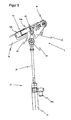
- the FIG. 1 shows a side view of a transport device 1.
- the transport device 1 is designed as a device for sorting piece goods. It has a conveyor frame 17, on which two pivotable conveyor tables 12 and 13 are supported.
- the conveyor frame 17 is provided on its underside with feet 18, which can be adjusted via an adjusting thread in height to allow a horizontal alignment of the transport device even on uneven ground.
- conveyor tables 12 and 13 are shown in a swung-out position. In normal operating position or neutral position, the two conveyor tables 12 and 13 are arranged in a common conveying plane in alignment with each other.
- conveyor belts can be connected to z. B. from the left side of cargo to the transport device and dissipate on the right side of the presentation piece goods. The presentation of the FIG. 1 is selected so that the conveying direction runs from left to right.
- General cargo is sorted out by the transport device by the piece goods from the left on the transport device, ie on the first conveyor table 12 is promoted this is lowered as shown below and sorted out the cargo down.
- the second conveyor table 13 is at the same time ie synchronously pivoted with the first conveyor table 12 upwards, so that on the one hand, the resulting gap between the two conveyor tables 12 and 13, a large free Has height and on the other hand, the respective pivoting for the individual conveyor table 12 and 13 may be relatively low.
- the cargo is conveyed down along the conveyor table 12 and can be transported there by means of another conveyor belt or recorded in a collection box.
- the transport device has a pivot drive 2 with a linear drive, wherein each conveyor table own lifting cylinders 21 and 22 are assigned. Each conveyor table two lifting cylinders are provided, which attack at the same height to both sides of a conveyor table. In the figures, only the front lifting cylinder is shown in the side view.
- the lifting cylinders are pivotally mounted at its lower end to a holding plate 23.
- the holding plate 23 is fixedly connected to the conveyor frame 17 by screws or rivets.
- the holding plate has a mechanical guide 27 by means of horizontally displaceable holders for the lifting cylinders 21, 22.
- the two conveyor tables 12 and 13 are arranged in mirror image to each other, and constructed of the same components.
- the description can be limited to a single conveyor table, the description then automatically applies simultaneously for the second conveyor table.
- the two conveyor tables 12, 13 are designed to be manually detachable via tension locks. This means, each of the conveyor tables 12 and 13, respectively can be removed by loosening the fasteners with a few simple steps of the conveyor frame 17. Subsequently, the removed conveyor table can be cleaned or a new or repaired conveyor table can be connected to the conveyor frame 17. The connecting of the conveyor table is done analogously by closing the buckles.
- the pivot drive 2 for the conveyor tables 12 and 13 comprises on the one hand the pivotable mounting of the conveyor tables about the pivot axis A and B as the other the linear drive comprising a fixed to the conveyor frame support plate 23 on which the two lifting cylinders 21 and 22 are mounted.
- Their power is supplied via pneumatic lines, not shown, which supply them with compressed air via valve connections of the lifting cylinders 26a and 26b.
- the compressed air comes from a separate compressed air network or is provided by a compressor, not shown.
- the two conveyor tables 12 and 13 are mounted on the conveyor frame 17 in each case via a pivot bearing 3.
- the conveyor table 12 and 13 each have a belt body 16 over which an endless belt is guided.
- the endless belt is deflected by means of rollers which, viewed in the conveying direction, are arranged at the two ends of the conveyor table 12 and 13, respectively.
- the guide rollers are configured once as a driven transport roller 14 and once as a loosely moving guide roller 15, wherein the transport roller 14 is arranged in each case in the region of the pivot bearing 3 and the guide roller 15 is arranged at the opposite end of the conveyor table 12 and 13 respectively.
- Around Deflection roller 15 is a receptacle 5 is provided which supports a lifting cylinder of the linear drive.
- the pivoting operation of the conveyor tables 12 and 13 is controlled by a control device 19.
- the control device 19 has arranged on the support feet 18 valve blocks 19 a and 19 b and controls the power supply or compressed air supply to the terminals 26 a and 26 b of the lifting cylinder via these valve blocks.
- the control device controls the two conveyor tables 12 and 13 so that the first, upstream conveying table, as seen in the conveying direction, as in FIG. 1 is shown pivoted down, and seen in the conveying direction second, downstream table is pivoted upwards.
- control device may also control the conveyor tables 12, 13 in such a way that the first table 12 seen in the conveying direction is pivoted upwards and the second table 13, viewed in the conveying direction, is pivoted downwards.
- first table 12 seen in the conveying direction is pivoted upwards
- second table 13 viewed in the conveying direction is pivoted downwards.
- this application not shown in the figures, is transported from the first conveyor table 12 from the piece goods to an overhead conveyor belt, at the same time, for example, via the second conveyor table 13 delivered from a lower feed belt can be taken.
- the conveyor table 12 has a band body 16 over which an endless belt is guided, wherein the endless belt is guided at the ends of the belt body via the deflection roller 15 and via the transport roller 14.
- the endless belt is guided at the ends of the belt body via the deflection roller 15 and via the transport roller 14.
- On the upper side of the belt body 16 runs the upper run of the endless belt and on the underside of the belt body 16 runs the lower run 11b of the endless belt.
- the conveyor table 12 is connected via a lifting cylinder 21 and the bearing 3 with the conveyor frame 17. With a decrease of the conveyor table 12 of the conveyor frame 17, only the connection of the conveyor table 12 has to be solved to the pivot bearing and the lifting cylinder.
- the pivot bearing 3 is designed in two parts, wherein the two parts in the operating position, in the FIG. 2 is shown, are arranged partially overlapping each other.
- the pivot bearing 3 is shown in the open position.
- the conveyor table 12 can be removed by lifting the conveyor table upwards, or a connection between a conveyor table 12 newly inserted into the bearing 3 and the conveyor frame can be made by closing the bearing 3.
- the two parts 31 and 32 of the bearing 3 are shown pivoted against each other. The shape of the two parts 31 and 32 is thus from the FIG. 3 better visible.
- two identically constructed pivot bearings 3 are used, which support the transport roller 14 on both sides of the belt body 16. In the Side view of the figures, only the front pivot bearing 3 is shown in each case.
- the two parts of the bearing 31 and 32 are connected to each other via a tension lock 33.
- the tension lock 33 has a resilient clamp 33a, which engages over a screw 33c arranged on the first part 31 of the bearing and connects the two parts to one another via a bracket 33b arranged on the second part of the bearing 32.
- the two interconnected parts hold in the in FIG. 2 illustrated, locked position, the drive roller 14 in a bearing shell, which is formed by the two parts 31 and 32, respectively.
- Each of the two parts 31 and 32 has for this purpose a recess whose contour is formed so that the two connected via the tension lock 33 parts 31 and 32 together form a bearing shell in which an adapter or a bushing 34 of the transport roller is supported. This ensures that when closing the tension lock 33, the transport roller 14 is held securely and largely free of play in the pivot bearing 3.
- an automatic adjustment of the transport roller 14 is achieved by tensioning the tension lock 33 via the positioning of the bushing 34 within the recess.
- the drive roller 14 has in extension of its axis on a socket 34 which engages in the bearing shell of the bearing 3.
- the sleeve is secured in the pivot bearing 3 against axial displacement by the sleeve 34 has a circumferential groove whose dimensions are matched to the two parts of the bearing 31 and 32, so that These engage in the groove and record the socket fit.
- the guide roller 15 is arranged.
- a receptacle 5 is arranged, which is fixedly connected to the belt body 16 and via which the lifting cylinder 21 is releasably connected to the conveyor table 12.
- the lifting cylinder 21 has a cylinder housing 24 and a piston rod 25.
- the lifting cylinder 21 is designed as a pneumatic cylinder and is supplied via two valve ports 26a and 26b with compressed air.
- the lifting cylinder 21 is a double-acting lifting cylinder and is driven in both working cycles, ie both when lifting and when lowering via compressed air.
- a single-acting lifting cylinder could be used, in which then only one power stroke, either lifting or lowering, is driven by compressed air, and the second power stroke is then performed by a spring arranged within the lifting cylinder.
- the receptacle 5 is formed in two parts. It has a first part 51, which is fixedly connected to the conveyor belt body 16 and a second part 52 which is pivotally mounted on the first part on.
- FIG. 5 a detailed representation of the open receptacle 5 is shown.
- the two parts of the receptacle 51 and 52 are connected to each other via a pivot point 58, and are by means of a clamping closure 53 in the in the FIG. 2 shown locked position firmly connected.
- This tension lock 53 must be solved.
- the tension lock 53 has a resilient clamp 53a on which a screw arranged on the second part of the receptacle 52 surrounds and can be tensioned by means of a bracket 53b arranged on the belt body 16 or on the first part 51.
- the axis 54 is first inserted into the recess between the open parts of the receptacle 51 and 52. Subsequently, the receptacle 5 is locked by closing the tension lock 53.
- the two interconnected parts 51 and 52 support in the in FIG. 2 illustrated, locked position, the piston rod 25 in a two-part bearing shell of the receptacle 5, which is formed by the two parts 51 and 52, respectively.
- Each of the two parts 51 and 52 has for this purpose a recess, the contour of which is formed so that the two connected via the tension lock 53 parts 51 and 52 together form a bearing shell in which a port 54 of the piston rod 25 is supported.
- the open position of the receptacle 5 can be seen from the FIG. 5 remove.
- connection 54 is designed as a connection axis, and connects the two transverse to the conveying direction at the same height of the conveyor table 12 arranged lifting cylinder with each other, so that they are mechanically connected to each other not only on the conveyor belt body 16 but on the additional axis 54 and thus stabilized.
- This additional axis 54 causes the connected lifting cylinders stabilize each other with the delivery table 12 removed.
- the connecting shaft 54 is in each case movably mounted in the piston rods 25.
- the deflection roller 15 is variably configured in its distance from the conveyor belt body 16 in which the distance can be set via a cam and an adjustment screw supported on this cam.
- the belt tension of the revolving endless belt is adjusted to z. B. to allow a fine adjustment of the conveyor belt on the belt body 16.
- To decrease the conveyor belt whose belt tension is reduced which is done by turning a lever which acts on a cam of the guide roller 15 and thus reduces their distance from the belt body 16.
- the relaxed endless belt can be removed and replaced with a new one.
- FIG. 3 the open pivot bearing 3 is shown.
- the first part 31 of the bearing 3 is fixedly connected to the conveyor frame 17 by a base 39 is provided on its underside, which is fastened to the conveyor frame 16 via screws or rivets.
- a pivot 38 is provided which rotatably supports the second part of the bearing 32. After opening the tension lock 33, the second part 32 of the bearing 3 can be pivoted in the direction of the arrow can.
- a drive motor 4 is supported.
- the drive motor 4 is at least indirectly connected via the first part 31 of the bearing 3 with the conveyor frame 17 and held mechanically stable.
- the drive motor 4 is provided only on one side of the conveyor table.
- the rear pivot bearing 3, which lies behind in the representation of the figures and therefore not shown, has no drive motor 4 by default.
- both pivot bearings may have a separate drive motor 4.
- the drive motor 4 is designed as an electric motor and has as a drive pulley or a gear 42 through which a toothed belt 41, the in FIG. 4 is shown in more detail, is performed.
- the toothed belt 41 meshes on one side with the output of the electric motor 4 and on the other side with a gear, which is fixedly connected to the transport roller 14 of the conveyor table.
- the toothed belt 41 For trouble-free operation of the drive, it is necessary that the toothed belt 41 is well tensioned. To remove the conveyor table, however, the toothed belt must be relaxed, since the conveyor table 41 would not be removable due to the forces prevailing due to the tension when the toothed belt 41 is tensioned.
- the pivot bearing 3 on a backdrop curve 35 which has a recess 36 on the one hand, the adapter 34 in normal operation the transport roller holds.
- the position of the recess 36 is dimensioned so that the distance from the transport roller to the electric motor 4 exactly matches the length of the tensioned toothed belt 41, so that it is well tensioned in the operating position.
- the slide guide 35 has a further recess 37.
- the further recess 37 connects directly to the recess 36 and provides a guide for the sleeve 34 of the transport roller 14 by the groove of the sleeve 34 slides along the contour of the slide curve.
- the guiding of the bushing 34 along the sliding cam 35 reduces the distance of the transport roller 14 to the drive motor 4, so that when the transport roller is guided along the sliding cam 35 towards the receptacle 37, the toothed belt 41 is relaxed.
- the relaxed toothed belt 41 can now be easily removed from the pinion 42 of the electric motor, and thus lift the conveyor belt body 16 of the pivot bearing 3.
- the open receptacle 5 is shown. It is designed as a two-part bearing.
- the receptacle 5 has a first part 51, which is fixed to the band body 16 is connected, preferably screwed or riveted thereto, and a second part 52 which is rotatably supported by a fulcrum 58 on the first part 51.
- the part 51 and the part 52 each have a recess, the dimensions of which are in turn adapted to the axis 54 of the lifting cylinder 21, so that it can be accommodated accurately and without play in the recess formed between the part 51 and the part 52.
Landscapes
- Engineering & Computer Science (AREA)
- Mechanical Engineering (AREA)
- Structure Of Belt Conveyors (AREA)
Abstract
Description
- Die Erfindung betrifft eine Transportvorrichtung gemäß den Merkmalen des Oberbegriffs des Anspruchs 1.
- Bei Transportvorrichtungen mit Förderbändern besteht in der Praxis oftmals die Notwendigkeit, Teile des Förderbandes abnehmen zu können.
- So ist aus der
DE 10 2004 034 653 A1 eine Transportvorrichtung für eine Waage bekannt, bei der der Fördertisch ein über einen Motor mit Riementrieb angetriebenes Endlosband aufweist und mit einer Wägezelle zusammenwirkt. Der Fördertisch kann zum Reinigen von der Wägezelle abgenommen werden. - In der
DE 602 01 211 T2 ist eine Fördervorrichtung gezeigt, die einen abnehmbaren Bandkörper aufweist, über den ein angetriebenes Endlosband geführt ist. Der Bandkörper ist zweiteilig ausgebildet und in einem separaten Lagerrahmen gehaltert. Zum Abnehmen wird der zweiteilige Bandkörper abgeknickt und eine Kupplung zum Antriebsmotor getrennt. - Der Erfindung liegt die Aufgabe zugrunde eine Transportvorrichtung zu schaffen, die konstruktiv einfach aufgebaut ist und dabei einfach zu reinigen ist und einen geringen Wartungsaufwand benötigt.
- Diese Aufgabe wird erfindungsgemäß mit einer Transportvorrichtung gemäß den Merkmalen des Anspruchs 1 gelöst.
- Die Transportvorrichtung weist einen Förderrahmen mit einem zweiteiligen Lager zum Haltern der Transportwalze bzw. der Umlenkwalze eines Fördertisches auf. Durch Trennen der beiden Teile des Lagers wird die Transportwalze bzw. die Umlenkwalze freigegeben. Der Fördertisch ist im Betrieb der Transportvorrichtung über die Umlenkwalze und/oder die Transportwalze mit dem Förderrahmen verbunden, somit kann der Fördertisch einfach durch Öffnen dieser Verbindung gelöst werden. Das Trennen der beiden Teile kann auf einfache Art und Weise manuell erfolgen, indem z. B. ein Schnellverschluss geöffnet wird, der die beiden Teile des Lagers in Betriebstellung miteinander verbindet.
- Der Schnellverschluss kann als ein manuell zu öffnender Spannverschluss oder Riegelverschluss oder Knebelverschluss ausgebildet sein. Der Spannverschluss verbindet die beiden Lagerteile über eine federbelastete Klammer. Der Riegelverschluss verbindet die beiden Lagerteile über einen federbelasteten Riegel. Der Knebelverschluss verbindet die beiden Lagerteile über einen federbelasteten Knebel. Dadurch ist es möglich einerseits eine mechanisch sichere und stabile Verbindung der beiden Lagerteile zu erreichen und andererseits die Lagerteile ohne Werkzeug einfach durch manuelles Öffnen des Schnellverschlusses zu trennen.
- In einer Ausführung ist vorgesehen, dass das erste Teil des Lagers fest mit dem Förderrahmen verbunden ist. Das zweite Teil des Lagers ist schwenkbar an dem Förderrahmen oder an dem ersten Teil befestigt. Das ermöglicht ein Trennen der beiden Teile des Lagers mittels einer einfachen Schwenkbewegung. Zudem sind so die beiden Teile unverlierbar miteinander bzw. mit der Transportvorrichtung verbunden.
- Um eine mechanisch sichere und passgenaue Halterung des Fördertisches zu erreichen ist vorgesehen, dass ein Spannverschluss die beiden Teile des Lagers miteinander verbindet. Der Spannverschluss weist eine federnde Klammer und einen Spannbügel zum Spannen der Klammer auf. Es kann vorgesehen sein, dass jede Umlenkwalze bzw. Transportwalze zwei solcher Spannverschlüsse aufweist. Jedoch genügt es bereits, wenn ein Spannverschluss auf einer Seite der Walze angeordnet ist und die andere Seite der Walze z. B. durch Einführen einer Achsverlängerung in eine passgenaue Aussparung gehaltert wird.
- In einer Ausgestaltung ist vorgesehen, dass die Transportwalze über einen Motor angetrieben ist. Der Motor kann dazu in der Transportwalze integriert sein. Dies stellt eine besonders platzsparende Lösung dar. In einer alternativen Ausführung kann der Motor am Förderrahmen angeordnet sein und die Transportwalze über ein Getriebe oder einen Zahnriemen antreiben. Dies stellt eine Lösung dar, bei der ein kostengünstiger Antriebsmotor verwendet werden kann und zugleich die Masse des Fördertisches verringert wird. Letzteres ist von besonderer Bedeutung, wenn der Fördertisch automatisch angetrieben verschwenkt werden soll, oder wenn der Fördertisch mit einer Wägezelle zur Gewichtsermittlung von Stückgut zusammenwirkt. Bei der Gewichtsermittlung kommt es insbesondere darauf an, das Gewicht des Fördertisches gering zu halten, das dieser als Vorlast auf die Wägezelle wirkt und mit seinem Eigengewicht deren Empfindlichkeit beeinflusst.
- Um bei einem Antrieb über einen Zahnriemen sicherzustellen dass dieser im Betrieb die notwendige Spannung aufweist, weist das Lager eine Aufnahme zur Halterung der Transportwalze auf, die durch eine Aussparung gebildet ist, deren Entfernung zum Motor auf die Länge des gespannten Zahnriemens abgestimmt ist. Die Aussparung ist zudem so geformt, dass sie die Transportwalze von unten her stützt und diese auch bei geöffnetem Lager in der Aussparung sicher gehaltert ist. Dies verhindert, dass beim Öffnen des Verschlusses bzw. Trennen der Lagerteile der Fördertisch z. B. nach unten fällt bzw. aufgrund des gespannten Zahnriemens nach unten gezogen wird. Da die Transportwalze bei gespanntem Zahnriemen nicht anzuheben ist, muss dieser beim Abnehmen des Fördertisches zunächst entspannt werden.
- Dazu kann vorgesehen sein, dass das Lager eine Kulissenkurve bzw. eine Kulissenbahn aufweist, entlang derer die Transportwalze in Richtung zum Motor hin geführt werden kann, um den Zahnriemen zu entspannen. In ihrer axialen Verlängerung weist die Transportwalze einen als Kulissenstein ausgebildeten Adapter,auf. Zur Befestigung des Adapters ist vorgesehen, dass dieser mit der Achse der Transportwalze verschraubt oder verklebt werden kann. Der Adapter kann als runde Buchse ausgebildet sein, die an ihrem Umfang eine geschlossen umlaufende Nut aufweist, in die die beiden Lagerteile zum Führen der Achse eingreifen. Über diese Nut wird zum einen eine Einführhilfe beim Einsetzen der Transportwalze in die Kulissenführung und zum anderen eine Zwangsführung der Transportwalze gewährleistet. Zugleich sichert die Nut die Transportwalze gegen ein axiales Verschieben.
- In einer Ausgestaltung ist vorgesehen, dass die Kulissenkurve in dem ersten, feststehenden Teil des Lagers angeordnet ist. So wird gewährleistet, dass die Transportwalze auch bei getrennten Lagerhälften sicher geführt wird. In dem zweiten, verschwenkbaren Teil des Lagers ist eine Aussparung vorgesehen, die so bemessen und angeordnet ist, dass sie die Kulissenkurve in Betriebsstellung, also bei miteinander verbundenen Lagerteilen, abdeckt. In der Betriebsstellung bilden die beiden unmittelbar aneinanderliegenden Aussparungen der beiden Lagerteile eine Aussparung, die so bemessen ist, dass die Transportwalze bzw. ein Adapter der Transportwalze in dieser Aussparung passgenau und insbesondere spielfrei aufgenommen werden kann.
- In einer Ausgestaltung ist vorgesehen, dass der Fördertisch um eine Achse schwenkbar ist. So kann z. B. mit einem schwenkbaren Fördertisch eine Sortiervorrichtung oder eine Wägezelle, z.B. für Kontrollwaagen oder Checkweigher aufgebaut werden.
- Bei der Anwendung der Transportvorrichtung bei einer Sortiervorrichtung wird der schwenkbare Fördertisch dazu verwendet, um Stückgut aus einer Förderebene heraus zu sortieren. Dies geschieht vorzugsweise mittels eines Schwenkantriebs, der den Fördertisch automatisch verschwenkt. Der Schwenkantrieb kann dabei in der Schwenkachse des Fördertisches angreifen. Vorzugsweise ist vorgesehen, dass die Schwenkachse eines Fördertisches durch dessen angetriebene Transportwalze hindurch verläuft. Insbesondere ist es vorteilhaft, wenn die Transportwalze die Schwenkachse des jeweiligen Fördertisches bildet. Dies ermöglicht einen konstruktiv besonders einfachen Aufbau, da die drehbare Transportwalze als solche gleichzeitig das Drehlager des Fördertisches bildet.
- In einer weiteren Ausgestaltung kann der Schwenkantrieb als Linearantrieb ausgebildet sein, der an dem Bandkörper des Fördertisches angreift. In letzterem Falle ist vorgesehen, dass auch die Verbindung von Linearantrieb und Fördertisch als zweiteilige Aufnahme ausgestaltet ist, die über einen manuell betätigbaren Spannverschluss zu öffnen ist. Somit kann durch Lösen der manuell zu betätigenden Spannverschlüsse von Schwenklager und Aufnahme der Fördertisch komplett abgenommen werden. Diese Ausgestaltung hat den Vorteil, dass der Fördertisch als Ganzes abnehmbar ist und dass kein zusätzlicher Halterahmen erforderlich ist.
- Bei einer Anwendung der Transportvorrichtung bei einer Wägezelle kann der Fördertisch anhand des Gewichtes von transportiertem Stückguts um seine Schwenkachse verschwenkt werden. Beim Fördern des Stückguts entlang des Fördertisches entsteht so eine variable Gewichtskraft, die mittels einer Kraftmesszelle ermittelt werden kann.
- Eine Verwendung der Transportvorrichtung ist z.B. bei der Herstellung von Lebensmitteln, die als Stückgut verpackt werden, vorgesehen. Jedoch ist die Verwendung der Transportvorrichtung in allen Bereichen der Fertigung oder Logistik wie z.B. bei Paketdiensten möglich, in denen auf Wartungsfreundlichkeit oder Hygiene Wert gelegt wird.
- Weitere Ausführungsbeispiele der Erfindung sind in den Figuren dargestellt und der dazugehörenden Beschreibung beschrieben.
-
- Figur 1:
- Ein Ausführungsbeispiel der erfindungsgemäßen Transportvorrichtung bei einer Sortiervorrichtung.
- Figur 2:
- Eine schematische Darstellung eines einzelnen Fördertisches in ausgeschwenkter Position.
- Figur 3:
- Eine vergrößerte Darstellung des Schwenklagers eines Fördertisches.
- Figur 4:
- Eine vergrößerte Darstellung des Schwenklagers eines Fördertisches bei dessen Demontage vom Förderrahmen.
- Figur 5:
- Eine Detaildarstellung des Anschlusses eines Hubzylinders an den Fördertisch.
- Die
Figur 1 zeigt eine Seitenansicht einer Transportvorrichtung 1. Die Transportvorrichtung 1 ist als Vorrichtung zum Sortieren von Stückgut ausgebildet. Sie weist einen Förderrahmen 17 auf, an dem zwei schwenkbare Fördertische 12 und 13 gehaltert sind. Der Förderrahmen 17 ist an seiner Unterseite mit Standfüßen 18 versehen, die über ein Justiergewinde in der Höhe verstellt werden können, um auch bei unebenem Untergrund eine horizontale Aufstellung der Transportvorrichtung zu ermöglichen. - In der Darstellung der
Figur 1 sind beide Fördertische 12 und 13 in einer ausgeschwenkten Position dargestellt. In normaler Betriebsstellung oder Neutralstellung sind die beiden Fördertische 12 und 13 in einer gemeinsamen Förderebene fluchtend zueinander angeordnet. An die Transportvorrichtung links bzw. rechts in der Darstellung derFigur 1 können weitere, nicht dargestellte Förderbänder angeschlossen werden, um z. B. von der linken Seite aus Stückgut zu der Transportvorrichtung zuzuführen und auf der rechten Seite der Darstellung Stückgut abzuführen. Die Darstellung derFigur 1 ist so gewählt, dass die Förderrichtung von links nach rechts verläuft. - Stückgut wird von der Transportvorrichtung aussortiert, indem das Stückgut von links auf die Transportvorrichtung d.h. auf den ersten Fördertisch 12 gefördert wird dieser wie dargestellt nach unten abgesenkt ist und das Stückgut nach unten aussortiert. Der zweite Fördertisch 13 wird zeitgleich d. h. synchron mit dem ersten Fördertisch 12 nach oben verschwenkt, sodass zum einen der entstehende Zwischenraum zwischen den beiden Fördertischen 12 und 13 eine große freie Höhe aufweist und zum anderen der jeweilige Schwenkweg für den einzelnen Fördertisch 12 und 13 relativ gering sein kann. Das Stückgut wird entlang des Fördertisches 12 nach unten gefördert und kann dort mittels eines weiteren Förderbandes weitertransportiert oder in einer Sammelbox aufgenommen werden.
- Die Transportvorrichtung weist einen Schwenkantrieb 2 mit einem Linearantrieb auf, wobei jedem Fördertisch eigene Hubzylinder 21 bzw. 22 zugeordnet sind. Je Fördertisch sind zwei Hubzylinder vorgesehen, die auf gleicher Höhe zu beiden Seiten eines Fördertisches angreifen. In den Figuren ist in der Seitenansicht jeweils nur der vordere Hubzylinder dargestellt. Die Hubzylinder sind an ihrem unteren Ende an einer Halteplatte 23 schwenkbar gelagert. Die Halteplatte 23 ist über Schrauben oder Nieten fest mit dem Förderrahmen 17 verbunden. An Ihrem oberen Bereich weist die Halteplatte eine mechanische Führung 27 mittels horizontal verschiebbaren Halterungen für die Hubzylinder 21, 22 auf.
- Die beiden Fördertische 12 und 13 sind spiegelbildlich zueinander angeordnet, und aus den gleichen Bauteilen aufgebaut. Somit kann sich die Beschreibung auf einen einzelnen Fördertisch beschränken, wobei die Beschreibung dann automatisch auch gleichzeitig für zweiten Fördertisch gilt.
- Um eine gute Reinigung und/oder Wartung der Transportvorrichtung 1 zu ermöglichen, sind die beiden Fördertische 12, 13 über Spannverschlüsse manuell abnehmbar ausgebildet. Das bedeutet, jeder der Fördertische 12 bzw. 13 kann durch Lösen der Spannverschlüsse mit wenigen Handgriffen von dem Förderrahmen 17 abgenommen werden. Anschließend kann der abgenommene Fördertisch gereinigt werden oder ein neuer bzw. reparierter Fördertisch kann mit dem Förderrahmen 17 verbunden werden. Das Verbinden des Fördertisches erfolgt sinngemäß durch Schließen der Spannverschlüsse.
- Der Schwenkantrieb 2 für die Fördertische 12 und 13 umfasst zum einen die schwenkbare Lagerung der Fördertische um deren Schwenkachse A bzw. B wie zum anderen den Linearantrieb umfassend einen an dem Förderrahmen befestigte Halteplatte 23 an der die beiden Hubzylinder 21 und 22 gelagert sind. Deren Energieversorgung erfolgt über nicht dargestellte Pneumatikleitungen die über Ventilanschlüsse der Hubzylinder 26a und 26b diese mit Druckluft versorgen. Die Druckluft kommt von einem separaten Druckluftnetz bzw. wird von einem nicht dargestellten Kompressor bereitgestellt. Die beiden Fördertische 12 und 13 sind an dem Förderrahmen 17 jeweils über ein Schwenklager 3 gelagert.
- Die Fördertisch 12 bzw. 13 weisen jeweils einen Bandkörper 16 auf über den ein Endlosband geführt wird. Das Endlosband wird über Walzen umgelenkt, die in Förderrichtung gesehen an den beiden Enden des Fördertisches 12 bzw. 13 angeordnet sind. Die Umlenkwalzen sind einmal als angetriebene Transportwalze 14 und einmal als lose laufende Umlenkwalze 15 ausgestaltet, wobei die Transportwalze 14 jeweils im Bereich des Schwenklagers 3 angeordnet ist und die Umlenkwalze 15 an dem gegenüberliegenden Ende des Fördertisches 12 bzw. 13 angeordnet ist. Im Bereich der Umlenkwalze 15 ist eine Aufnahme 5 vorgesehen, die einen Hubzylinder des Linearantriebs haltert.
- Der Schwenkvorgang der Fördertische 12 bzw. 13 wird über eine Steuervorrichtung 19 gesteuert. Die Steuervorrichtung 19 weist an den Haltefüßen 18 angeordnete Ventilblöcke 19a bzw. 19b auf und steuert über diese Ventilblöcke die Energie- bzw. Druckluftzufuhr zu den Anschlüssen 26a und 26b der Hubzylinder. Die Steuervorrichtung steuert die beiden Fördertische 12 bzw. 13 so an, dass der in Förderrichtung gesehene erste, stromaufwärts liegende Fördertisch, wie in der
Figur 1 dargestellt nach unten verschwenkt wird, und der in Förderrichtung gesehene zweite, stromabwärts liegende Tisch nach oben verschwenkt wird. Das hat den Vorteil, dass der Sortiervorgang des Stückguts von der Schwerkraft unterstützt abläuft, indem das Stückgut sozusagen bergab aussortiert wird und mit seinem Eigengewicht, den Sortiervorgang unterstützt. Alternativ dazu kann die Steuervorrichtung die Fördertische 12, 13 auch so ansteuern, dass der in Förderrichtung gesehen erste Tisch 12 nach oben verschwenkt wird und der in Förderrichtung gesehen zweite Tisch 13 nach unten verschwenkt wird. In diesem, in den Figuren nicht dargestellten Anwendungsfall, wird von dem ersten Fördertisch 12 aus das Stückgut zu einem oben liegenden Förderband transportiert, wobei gleichzeitig z.B. über den zweiten Fördertisch 13 ein von einem unten liegenden Zuführband geliefertes Stückgut aufgenommen werden kann. - In der
Figur 2 ist ein Fördertisch im Detail dargestellt. Der Fördertisch 12 weist einen Bandkörper 16 auf, über den ein Endlosband geführt ist, wobei das Endlosband an den Enden des Bandkörpers über die Umlenkwalze 15 und über die Transportwalze 14 geführt wird. Auf der Oberseite des Bandkörpers 16 verläuft das obere Trum des Endlosbandes und an der Unterseite des Bandkörpers 16 verläuft das untere Trum 11b des Endlosbandes. - Der Fördertisch 12 ist über einen Hubzylinder 21 und über das Lager 3 mit dem Förderrahmen 17 verbunden. Bei einer Abnahme des Fördertisches 12 von dem Förderrahmen 17, muss lediglich die Verbindung des Fördertisches 12 zu dem Schwenklager und dem Hubzylinder gelöst werden.
- Das Schwenklager 3 ist zweiteilig ausgestaltet, wobei die beiden Teile in der Betriebsstellung, die in der
Figur 2 dargestellt ist, einander teilweise überdeckend angeordnet sind. - In der
Figur 3 wird dagegen das Schwenklager 3 in geöffneter Position dargestellt. Bei geöffnetem Lager 3 kann eine Entnahme des Fördertisches 12 durch Abheben des Fördertisches nach oben erfolgen oder eine Verbindung eines neu in das Lager 3 eingesetzten Fördertisches 12 mit dem Förderrahmen durch Schließen des Lagers 3 erfolgen. In derFigur 3 sind die beiden Teile 31 bzw. 32 des Lagers 3 gegeneinander verschwenkt dargestellt. Die Form der beiden Teile 31 bzw. 32 ist somit aus derFigur 3 besser ersichtlich. Zum Haltern der Transportwalze 14 des Fördertisches 12 werden zwei gleichartig aufgebaute Schwenklager 3 verwendet, die die Transportwalze 14 zu beiden Seiten des Bandkörpers 16 haltern. In der Seitendarstellung der Figuren ist jeweils nur das vordere Schwenklager 3 dargestellt. - Die beiden Teile des Lagers 31 bzw. 32 sind über einen Spannverschluss 33 miteinander verbunden. Der Spannverschluss 33 weist eine federnde Klammer 33a auf die über eine an dem ersten Teil 31 des Lagers angeordnete Schraube 33c an diesem eingreift und über einen an dem zweiten Teil des Lagers 32 angeordneten Bügel 33b die beiden Teile miteinander verbindet. Die beiden miteinander verbundenen Teile haltern in der in
Figur 2 dargestellten, verriegelten Position die Antriebswalze 14 in einer Lagerschale, die durch die beiden Teile 31 bzw. 32 geformt wird. Jedes der beiden Teile 31 und 32 weist dazu eine Ausnehmung auf, deren Kontur so ausgeformt ist, dass die beiden über den Spannverschluss 33 verbundenen Teile 31 und 32 gemeinsam eine Lagerschale ausbilden in der ein Adapter bzw. eine Buchse 34 der Transportwalze gehaltert wird. So wird sichergestellt, dass beim Schließen des Spannverschlusses 33 die Transportwalze 14 sicher und weitgehend spielfrei in dem Schwenklager 3 gehaltert wird. Zudem wird durch das Spannen des Spannverschlusses 33 über die Positionierung der Buchse 34 innerhalb der Ausnehmung eine automatische Justierung der Transportwalze 14 erreicht. - Die Antriebswalze 14 weist in Verlängerung ihrer Achse eine Buchse 34 auf, die in die Lagerschale des Lagers 3 eingreift. Die Buchse wird in dem Schwenklager 3 gegen axiales Verschieben gesichert, indem die Buchse 34 eine umlaufende Nut aufweist, deren Abmessungen genau auf die beiden Teile des Lagers 31 und 32 abgestimmt ist, sodass diese in die Nut eingreifen und die Buchse passgenau aufnehmen.
- An dem stromabwärts liegenden Ende des Fördertisches 12 ist die Umlenkwalze 15 angeordnet. In deren Bereich ist eine Aufnahme 5 angeordnet, die mit dem Bandkörper 16 fest verbunden ist und über die der Hubzylinder 21 mit dem Fördertisch 12 lösbar verbunden ist.
- Der Hubzylinder 21 weist ein Zylindergehäuse 24 und eine Kolbenstange 25 auf. Der Hubzylinder 21 ist als Pneumatikzylinder ausgebildet und wird über zwei Ventilanschlüsse 26a und 26b mit Druckluft versorgt. Der Hubzylinder 21 ist ein doppelt wirkender Hubzylinder und wird in beiden Arbeitstakten, also sowohl beim Heben als auch beim Senken über Druckluft angetrieben. Alternativ könnte auch ein einfach wirkender Hubzylinder verwendet werden, bei dem dann nur ein Arbeitstakt, entweder Heben oder Senken, von Druckluft angetrieben wird, und der zweite Arbeitstakt dann von einer innerhalb des Hubzylinders angeordneten Feder ausgeführt wird.
- Am oberen Ende der Kolbenstange 25 ist ein als Achse ausgebildeter Anschluss 54 vorgesehen, der in einer Aussparung der Aufnahme 5 gehaltert ist. Die Aufnahme 5 ist dazu zweiteilig ausgebildet. Sie weist ein erstes Teil 51, welches fest mit dem Förderbandkörper 16 verbunden ist und ein zweites Teil 52, das an dem ersten Teil schwenkbar gelagert ist, auf.
- In der
Figur 5 ist eine Detaildarstellung der geöffneten Aufnahme 5 dargestellt. Die beiden Teile der Aufnahme 51 und 52 sind über einen Drehpunkt 58 miteinander verbunden, und werden mittels eines Spannverschlusses 53 bei der in derFigur 2 dargestellten verriegelten Position fest miteinander verbunden. Zur Abnahme des Fördertisches muss dieser Spannverschluss 53 gelöst werden. Der Spannverschluss 53 weist eine federnde Klammer 53a auf die eine an dem zweiten Teil der Aufnahme 52 angeordnete Schraube umgreift und mittels eines an dem Bandkörper 16 bzw. an dem ersten Teil 51 angeordneten Bügel 53b gespannt werden kann. Beim Verbinden des Fördertisches mit dem Hubzylinder wird zunächst die Achse 54 in die Aussparung zwischen die geöffneten Teile der Aufnahme 51 und 52 eingeführt. Anschließend wird durch Schließen des Spannverschlusses 53 die Aufnahme 5 verriegelt. - Die beiden miteinander verbundenen Teile 51 und 52 haltern in der in
Figur 2 dargestellten, verriegelten Position die Kolbenstange 25 in einer zweiteiligen Lagerschale der Aufnahme 5, die durch die beiden Teile 51 bzw. 52 geformt wird. Jedes der beiden Teile 51 und 52 weist dazu eine Ausnehmung auf, deren Kontur so ausgeformt ist, dass die beiden über den Spannverschluss 53 verbundenen Teile 51 und 52 gemeinsam eine Lagerschale ausbilden in der ein Anschluss 54 der Kolbenstange 25 gehaltert wird. Die geöffnete Position der Aufnahme 5 kann man aus derFigur 5 entnehmen. - Der Anschluss 54 ist als Verbindungsachse ausgebildet, und verbindet die beiden quer zur Förderrichtung auf gleicher Höhe des Fördertisches 12 angeordneten Hubzylinder miteinander, sodass diese nicht nur über den Förderbandkörper 16 sondern über die zusätzliche Achse 54 miteinander mechanisch verbunden und somit stabilisiert sind. Diese zusätzliche Achse 54 bewirkt, dass sich die verbundenen Hubzylinder bei abgenommenem Fördertisch 12 gegenseitig stabilisieren. Um Toleranzen auszugleichen ist vorgesehen, dass die Verbindungsachse 54 in den Kolbenstangen 25 jeweils beweglich gelagert ist.
- Die Umlenkwalze 15 ist in ihrem Abstand zum Förderbandkörper 16 variabel ausgestaltet, in dem über einen Nocken und eine sich auf diesem Nocken abstützende Verstellschraube der Abstand eingestellt werden kann. Durch variieren des Abstandes der Umlenkwalze 15 von dem Förderbandkörper 16 wird die Bandspannung des umlaufenden Endlosbandes eingestellt, um z. B. eine Feinjustierung des Förderbandes auf dem Bandkörper 16 zu ermöglichen. Zur Abnahme des Förderbandes wird dessen Bandspannung reduziert, was durch drehen eines Hebels erfolgt der auf einen Nocken der Umlenkwalze 15 wirkt und somit deren Abstand zum Bandkörper 16 verringert. Dadurch kann das entspannte Endlosband abgenommen und gegen ein neues getauscht werden.
- In der
Figur 3 ist das geöffnete Schwenklager 3 dargestellt. Der erste Teil 31 des Lagers 3 ist fest mit dem Förderrahmen 17 verbunden, indem an seiner Unterseite ein Sockel 39 vorgesehen ist, der über Schrauben oder Nieten an dem Förderrahmen 16 befestigt wird. Ein Drehpunkt 38 ist vorgesehen, der das zweite Teil des Lagers 32 drehbar lagert. Nach Öffnen des Spannverschlusses 33 kann das zweite Teil 32 des Lagers 3 in Pfeilrichtung aufgeschwenkt werden kann. An dem ersten Teil des Lagers 31 ist ein Antriebsmotor 4 gehaltert. Der Antriebsmotor 4 ist über den ersten Teil 31 des Lagers 3 zumindest mittelbar mit dem Förderrahmen 17 verbunden und mechanisch stabil gehaltert. Der Antriebsmotor 4 ist nur auf einer Seite des Fördertisches vorgesehen. Das in der Darstellung der Figuren hintenliegende und daher nicht gezeigte hintere Schwenklager 3 weist standarmäßig keinen Antriebsmotor 4 auf. - Es sind jedoch von der Darstellung der Figuren abweichende Ausführungen denkbar, bei denen es auf eine hohe Antriebsleistung ankommt. Bei diesen Anwendungen können beide Schwenklager einen separaten Antriebsmotor 4 aufweisen.
- Der Antriebsmotor 4 ist als Elektromotor ausgestaltet und weist als Abtrieb eine Riemenscheibe bzw. ein Zahnrad 42 auf, über das ein Zahnriemen 41, der in
Figur 4 näher dargestellt ist, geführt wird. Der Zahnriemen 41 kämmt auf einer Seite mit dem Abtrieb des Elektromotors 4 und auf der anderen Seite mit einem Zahnrad, welches fest mit der Transportrolle 14 des Fördertisches verbunden ist. - Für einen fehlerfreien Betrieb des Antriebs ist es erforderlich, dass der Zahnriemen 41 gut gespannt ist. Zum Abnehmen des Fördertisches, muss der Zahnriemen jedoch entspannt werden, da bei gespannten Zahnriemen 41 der Fördertisch aufgrund der durch die Spannung herrschenden Kräfte nicht abnehmbar wäre. Zu diesem Zweck weist das Schwenklager 3 eine Kulissenkurve 35 auf, die zum einen eine Aussparung 36 aufweist, die im Normalbetrieb den Adapter 34 der Transportwalze haltert. Die Lage der Aussparung 36 ist so bemessen, dass der Abstand von der Transportwalze zu dem Elektromotor 4 exakt mit der Länge des gespannten Zahnriemens 41 übereinstimmt, so dass dieser in der Betriebstellung gut gespannt ist.
- Zur Entnahme des Fördertisches 12 weist die Kulissenführung 35 eine weitere Aussparung 37 auf. Die weitere Aussparung 37 schließt sich direkt an die Aussparung 36 an und stellt eine Führung für die Buchse 34 der Transportwalze 14 dar, indem die Nut der Buchse 34 entlang der Kontur der Kulissenkurve gleitet. Das Führen der Buchse 34 entlang der Kulissenkurve 35 verringert die Distanz der Transportwalze 14 zu dem Antriebsmotor 4, sodass beim Führen der Transportwalze entlang der Kulissenkurve 35 hin zu der Aufnahme 37 der Zahnriemen 41 entspannt wird. Den entspannten Zahnriemen 41 kann man nun einfach von dem Zahnritzel 42 des Elektromotors abnehmen, und somit den Förderbandkörper 16 von dem Schwenklager 3 abheben. Beim Einsetzen des Fördertisches 12 geht man sinngemäß umgekehrt vor, indem man die Buchse 34 zunächst in die Aussparung 37 einsetzt, dort den Zahnriemen 41 über die Riemenscheiben 34a und 42 legt und dann die Transportwalze 14 entlang der Kulissenführung 35 hin zu der Aussparung 36 führt. Dabei wird dann der Zahnriemen 41 automatisch gespannt. Durch anschließendes Schließen des Spannverschlusses 33 wird die Transportwalze 14 mit dem Förderrahmen verbunden.
- In der
Figur 5 ist die geöffnete Aufnahme 5 dargestellt. Sie ist als zweiteiliges Lager ausgebildet. Die Aufnahme 5 weist ein erstes Teil 51 auf, welches fest an dem Bandkörper 16 verbunden ist, vorzugsweise mit diesem verschraubt oder vernietet, und eine zweites Teil 52, welches über einen Drehpunkt 58 drehbar an dem ersten Teil 51 gelagert ist. Das Teil 51 und das Teil 52 weisen jeweils eine Aussparung auf, deren Abmessungen wiederum auf die Achse 54 des Hubzylinders 21 angepasst ist, so dass diese passgenau und spielfrei in der zwischen dem Teil 51 und dem Teil 52 gebildeten Aussparung aufgenommen werden kann.
Claims (13)
- Transportvorrichtung für Stückgut mit einem angetriebenen Förderband, welches wenigstens einen von einem feststehenden Förderrahmen (17) abnehmbaren Fördertisch (12; 13) mit einem über eine angetriebene Transportwalze (14) und eine Umlenkwalze (15) geführten Endlosband aufweist,
dadurch gekennzeichnet,
dass der Förderrahmen (17) ein zweiteiliges Lager (3) zum Haltern der Transportwalze (14) und/oder der Umlenkwalze (15) aufweist, und das Lager (3) mittels eines Schnellverschlusses (33) zum Abnehmen des Fördertisches durch Trennen der beiden Lagerteile (31; 32) zu öffnen ist. - Transportvorrichtung nach Anspruch 1,
dadurch gekennzeichnet,
dass ein erstes Teil (31) des Lagers (3) feststehend mit dem Förderrahmen (17) verbunden ist und das zweite Teil (32) des Lagers schwenkbar mit dem Förderrahmen und/oder dem ersten Teil (31) des Lagers verbunden ist. - Transportvorrichtung nach Anspruch 1 oder 2,
dadurch gekennzeichnet,
dass der Schnellverschluss (33) als manuell zu öffnender Spannverschluss oder Riegelverschluss oder Knebelverschluss ausgebildet ist. - Transportvorrichtung nach Anspruch 1 oder 3,
dadurch gekennzeichnet,
dass der Schnellverschluss (33) als Spannverschluss ausgebildet ist, der zum Halten des Fördertisches die beiden Teile (31; 32) des Lagers (3) so miteinander verbindet, dass ein Adapter (34), vorzugsweise eine Achse der Transportwalze (14) oder Umlenkwalze (15), passgenau in dem Lager aufgenommen ist. - Transportvorrichtung nach Anspruch 4,
dadurch gekennzeichnet,
dass der Spannverschluss (33) eine Klammer (33a) aufweist, die an dem ersten Lagerteil (31) angreift und über einen an dem zweiten Lagerteil (32) angebrachten Bügel (33b) spannbar ist. - Transportvorrichtung nach einem der Ansprüche 1
bis 5,
dadurch gekennzeichnet,
dass die Transportwalze (14) über einen von einem Motor (4) angetriebenen Zahnriemen (41) angetrieben ist, indem der Motor an dem Förderrahmen (17) ortsfest gehaltert ist und der Zahnriemen (41) mit einem drehfest mit der Transportwalze (14) verbundenen Zahnrad (34a) kämmt. - Transportvorrichtung nach einem der Ansprüche 1
bis 6,
dadurch gekennzeichnet,
dass das erste Lagerteil (31) eine Kulissenkurve mit einer Halterungsaussparung (36) zum Haltern der Transportwalze (14) und einer von der Halterungsaussparung (36) ausgehenden Kulissenbahn zum Führen der Transportwalze (14) aufweist. - Transportvorrichtung nach einem der Ansprüche 1
bis 7,
dadurch gekennzeichnet,
dass das zweite Lagerteil (32) bei geschlossenem Spannverschluss (33) die Kulissenbahn des ersten Lagerteils (31) abdeckt, so dass die Transportwalze (14) ortsfest zwischen den beiden Lagerteilen (31; 32) gelagert ist. - Transportvorrichtung nach einem der Ansprüche 1
bis 8,
dadurch gekennzeichnet,
dass der Fördertisch (12; 13) schwenkbar gelagert ist, indem die Transportwalze (14) die Drehachse (A; B) des Fördertisches (12; 13) bildet. - Transportvorrichtung nach einem der Ansprüche 1
bis 9,
dadurch gekennzeichnet,
dass der Fördertisch (12; 13) einen Schwenkabtrieb (2) zum Schwenken des Fördertisches aufweist, der einen Linearantrieb mit einem elektrischen Spindeltrieb oder einem pneumatischen Hubzylinder (21; 22) aufweist. - Transportvorrichtung nach Anspruch 10,
dadurch gekennzeichnet,
dass der Linearantrieb mit dem Fördertisch lösbar verbunden ist, indem ein Anschluss (54) des Linearantriebs in einer zweiteiligen Aufnahme (5) gehaltert ist, und die Aufnahme (5), zum Abnehmen des Fördertisches (12; 13), durch trennen der beiden Aufnahmeteile (51, 52) zu öffnen ist. - Transportvorrichtung nach Anspruch 11,
dadurch gekennzeichnet,
dass ein erstes Teil (51) der Aufnahme (5) feststehend mit dem Fördertisch (12; 13) verbunden ist und das zweite Teil der Aufnahme (52) schwenkbar mit dem Fördertisch verbunden ist. - Transportvorrichtung nach Anspruch 11 oder 12,
dadurch gekennzeichnet,
dass zum Halten des Fördertisches (12; 13) ein lösbarer Spannverschluss (53) die beiden Teile (51; 52) der Aufnahme (5) so miteinander verbindet, dass der Anschluss des Linearantriebs passgenau in der Aufnahme (5) aufgenommen ist.
Applications Claiming Priority (1)
| Application Number | Priority Date | Filing Date | Title |
|---|---|---|---|
| DE102008020229A DE102008020229A1 (de) | 2008-04-22 | 2008-04-22 | Transportvorrichtung |
Publications (2)
| Publication Number | Publication Date |
|---|---|
| EP2112098A1 true EP2112098A1 (de) | 2009-10-28 |
| EP2112098B1 EP2112098B1 (de) | 2012-09-05 |
Family
ID=40802086
Family Applications (1)
| Application Number | Title | Priority Date | Filing Date |
|---|---|---|---|
| EP20090005221 Active EP2112098B1 (de) | 2008-04-22 | 2009-04-09 | Transportvorrichtung |
Country Status (3)
| Country | Link |
|---|---|
| EP (1) | EP2112098B1 (de) |
| DE (1) | DE102008020229A1 (de) |
| ES (1) | ES2393234T3 (de) |
Citations (3)
| Publication number | Priority date | Publication date | Assignee | Title |
|---|---|---|---|---|
| DE60201211T2 (de) | 2001-05-11 | 2005-09-22 | Ishida Co., Ltd. | Stückgutsortiervorrichtung mit Förderer |
| WO2005108249A2 (en) * | 2004-05-03 | 2005-11-17 | Johnson Food Equipment, Inc. | Belt conveyor with external drive |
| DE102004034653A1 (de) | 2004-07-16 | 2006-02-16 | Cfs Kempten Gmbh | Vorrichtung zur Bestimmung des Gewichtes von Produkten |
Family Cites Families (3)
| Publication number | Priority date | Publication date | Assignee | Title |
|---|---|---|---|---|
| GB581065A (en) * | 1944-10-13 | 1946-09-30 | Thomas Desmond Sutcliffe | Improvements in or relating to endless belt conveyors |
| US5984083A (en) * | 1997-03-10 | 1999-11-16 | Dorner Mfg. Corp. | Conveyor belt tensioning mechanism utilizing a manually operated cam-type tool |
| US6161683A (en) * | 1998-12-10 | 2000-12-19 | Borroughs Corporation | Conveyor quick release idler assembly |
-
2008
- 2008-04-22 DE DE102008020229A patent/DE102008020229A1/de not_active Withdrawn
-
2009
- 2009-04-09 ES ES09005221T patent/ES2393234T3/es active Active
- 2009-04-09 EP EP20090005221 patent/EP2112098B1/de active Active
Patent Citations (3)
| Publication number | Priority date | Publication date | Assignee | Title |
|---|---|---|---|---|
| DE60201211T2 (de) | 2001-05-11 | 2005-09-22 | Ishida Co., Ltd. | Stückgutsortiervorrichtung mit Förderer |
| WO2005108249A2 (en) * | 2004-05-03 | 2005-11-17 | Johnson Food Equipment, Inc. | Belt conveyor with external drive |
| DE102004034653A1 (de) | 2004-07-16 | 2006-02-16 | Cfs Kempten Gmbh | Vorrichtung zur Bestimmung des Gewichtes von Produkten |
Also Published As
| Publication number | Publication date |
|---|---|
| ES2393234T3 (es) | 2012-12-19 |
| DE102008020229A1 (de) | 2009-10-29 |
| EP2112098B1 (de) | 2012-09-05 |
Similar Documents
| Publication | Publication Date | Title |
|---|---|---|
| EP0438109B1 (de) | Trennvorrichtung für im wesentlichen quaderförmige Körper aus tiefgefrorenen Lebens- oder Futtermitteln | |
| DE69702664T2 (de) | Vorrichtung zum transportieren von gegenständen | |
| DE102017124170A1 (de) | Siebbandeinheit für eine Erntemaschine oder für eine Ernteguttransporteinheit, zugehörige Klappeneinheit | |
| AT401596B (de) | Siebvorrichtung für einen mähdrescher, insbesondere für einen versuchsfeldmähdrescher | |
| DE102017111060A1 (de) | Schneidwerk | |
| DE102010019284A1 (de) | Vorrichtung zur Umsetzung einer Drehbewegung in eine Linearbewegung | |
| DE102008020228B4 (de) | Sortiervorrichtung | |
| DE3329831A1 (de) | Universalschliessmaschine fuer die aufbringung von verschlusskappen auf behaelter | |
| DE69005249T2 (de) | Gerät für das Befestigen eines Halteteils auf Brillengläsern. | |
| DE4019031C2 (de) | Vorrichtung zum Verdrehen von mittels einer Fördereinrichtung tranportierten Werkstückträgern mit Werkstücken und Verwendung einer solchen Vorrichtung | |
| DD201922A5 (de) | Vorrichtung zum zufuehren von waeschestuecken zu einer mangel | |
| EP2112098B1 (de) | Transportvorrichtung | |
| DE69226976T2 (de) | Apparat zur Verarbeitung von Briefen | |
| DE3135988C2 (de) | Vorrichtung zur Halterung der Lagerträger einer Welle einer Bandumlenkung eines Bandförderers | |
| DE19943759C1 (de) | Einrichtung zur Handhabung blattartiger Gegenstände, insbesondere zum Zufördern von Kuverts zu einer Kuvertierstation | |
| DE4124797C2 (de) | Vorpositionier- und Zustellvorrichtung für Webschäfte in Webmaschinen | |
| DE3313196C1 (de) | Vorrichtung zum Spannen eines bandförmigen Förderorganes | |
| DE69226890T2 (de) | Apparat zur Verarbeitung von Briefen | |
| EP3456211A2 (de) | Vorrichtung zur halterung mindestens eines fingers | |
| DE102013015823A1 (de) | Anlegevorrichtung zum Zuführen von Produkten in einen Produktionsablauf | |
| DE202009009145U1 (de) | Riementrieb | |
| DE102011054057A1 (de) | Vorrichtung für die Herstellung von Filtern der Tabak verarbeitenden Industrie | |
| DE69422626T2 (de) | Zuführvorrichtung für schneidvorrichtung | |
| DE19529831B4 (de) | Strecke mit Verstellvorrichtung der Streckwerkswalzen | |
| DE202010011357U1 (de) | Walzenhaltevorrichtung |
Legal Events
| Date | Code | Title | Description |
|---|---|---|---|
| PUAI | Public reference made under article 153(3) epc to a published international application that has entered the european phase |
Free format text: ORIGINAL CODE: 0009012 |
|
| AK | Designated contracting states |
Kind code of ref document: A1 Designated state(s): AT BE BG CH CY CZ DE DK EE ES FI FR GB GR HR HU IE IS IT LI LT LU LV MC MK MT NL NO PL PT RO SE SI SK TR |
|
| 17P | Request for examination filed |
Effective date: 20091117 |
|
| GRAP | Despatch of communication of intention to grant a patent |
Free format text: ORIGINAL CODE: EPIDOSNIGR1 |
|
| GRAS | Grant fee paid |
Free format text: ORIGINAL CODE: EPIDOSNIGR3 |
|
| GRAA | (expected) grant |
Free format text: ORIGINAL CODE: 0009210 |
|
| AK | Designated contracting states |
Kind code of ref document: B1 Designated state(s): AT BE BG CH CY CZ DE DK EE ES FI FR GB GR HR HU IE IS IT LI LT LU LV MC MK MT NL NO PL PT RO SE SI SK TR |
|
| REG | Reference to a national code |
Ref country code: GB Ref legal event code: FG4D Free format text: NOT ENGLISH |
|
| REG | Reference to a national code |
Ref country code: CH Ref legal event code: EP |
|
| REG | Reference to a national code |
Ref country code: AT Ref legal event code: REF Ref document number: 574013 Country of ref document: AT Kind code of ref document: T Effective date: 20120915 |
|
| REG | Reference to a national code |
Ref country code: IE Ref legal event code: FG4D Free format text: LANGUAGE OF EP DOCUMENT: GERMAN |
|
| REG | Reference to a national code |
Ref country code: DE Ref legal event code: R096 Ref document number: 502009004585 Country of ref document: DE Effective date: 20121031 |
|
| REG | Reference to a national code |
Ref country code: ES Ref legal event code: FG2A Ref document number: 2393234 Country of ref document: ES Kind code of ref document: T3 Effective date: 20121219 |
|
| REG | Reference to a national code |
Ref country code: NL Ref legal event code: VDEP Effective date: 20120905 |
|
| PG25 | Lapsed in a contracting state [announced via postgrant information from national office to epo] |
Ref country code: HR Free format text: LAPSE BECAUSE OF FAILURE TO SUBMIT A TRANSLATION OF THE DESCRIPTION OR TO PAY THE FEE WITHIN THE PRESCRIBED TIME-LIMIT Effective date: 20120905 Ref country code: FI Free format text: LAPSE BECAUSE OF FAILURE TO SUBMIT A TRANSLATION OF THE DESCRIPTION OR TO PAY THE FEE WITHIN THE PRESCRIBED TIME-LIMIT Effective date: 20120905 Ref country code: LT Free format text: LAPSE BECAUSE OF FAILURE TO SUBMIT A TRANSLATION OF THE DESCRIPTION OR TO PAY THE FEE WITHIN THE PRESCRIBED TIME-LIMIT Effective date: 20120905 Ref country code: NO Free format text: LAPSE BECAUSE OF FAILURE TO SUBMIT A TRANSLATION OF THE DESCRIPTION OR TO PAY THE FEE WITHIN THE PRESCRIBED TIME-LIMIT Effective date: 20121205 |
|
| REG | Reference to a national code |
Ref country code: LT Ref legal event code: MG4D Effective date: 20120905 |
|
| PG25 | Lapsed in a contracting state [announced via postgrant information from national office to epo] |
Ref country code: SI Free format text: LAPSE BECAUSE OF FAILURE TO SUBMIT A TRANSLATION OF THE DESCRIPTION OR TO PAY THE FEE WITHIN THE PRESCRIBED TIME-LIMIT Effective date: 20120905 Ref country code: LV Free format text: LAPSE BECAUSE OF FAILURE TO SUBMIT A TRANSLATION OF THE DESCRIPTION OR TO PAY THE FEE WITHIN THE PRESCRIBED TIME-LIMIT Effective date: 20120905 Ref country code: SE Free format text: LAPSE BECAUSE OF FAILURE TO SUBMIT A TRANSLATION OF THE DESCRIPTION OR TO PAY THE FEE WITHIN THE PRESCRIBED TIME-LIMIT Effective date: 20120905 Ref country code: GR Free format text: LAPSE BECAUSE OF FAILURE TO SUBMIT A TRANSLATION OF THE DESCRIPTION OR TO PAY THE FEE WITHIN THE PRESCRIBED TIME-LIMIT Effective date: 20121206 |
|
| PG25 | Lapsed in a contracting state [announced via postgrant information from national office to epo] |
Ref country code: RO Free format text: LAPSE BECAUSE OF FAILURE TO SUBMIT A TRANSLATION OF THE DESCRIPTION OR TO PAY THE FEE WITHIN THE PRESCRIBED TIME-LIMIT Effective date: 20120905 Ref country code: IS Free format text: LAPSE BECAUSE OF FAILURE TO SUBMIT A TRANSLATION OF THE DESCRIPTION OR TO PAY THE FEE WITHIN THE PRESCRIBED TIME-LIMIT Effective date: 20130105 Ref country code: CZ Free format text: LAPSE BECAUSE OF FAILURE TO SUBMIT A TRANSLATION OF THE DESCRIPTION OR TO PAY THE FEE WITHIN THE PRESCRIBED TIME-LIMIT Effective date: 20120905 Ref country code: NL Free format text: LAPSE BECAUSE OF FAILURE TO SUBMIT A TRANSLATION OF THE DESCRIPTION OR TO PAY THE FEE WITHIN THE PRESCRIBED TIME-LIMIT Effective date: 20120905 Ref country code: EE Free format text: LAPSE BECAUSE OF FAILURE TO SUBMIT A TRANSLATION OF THE DESCRIPTION OR TO PAY THE FEE WITHIN THE PRESCRIBED TIME-LIMIT Effective date: 20120905 |
|
| PG25 | Lapsed in a contracting state [announced via postgrant information from national office to epo] |
Ref country code: PT Free format text: LAPSE BECAUSE OF FAILURE TO SUBMIT A TRANSLATION OF THE DESCRIPTION OR TO PAY THE FEE WITHIN THE PRESCRIBED TIME-LIMIT Effective date: 20130107 Ref country code: CY Free format text: LAPSE BECAUSE OF FAILURE TO SUBMIT A TRANSLATION OF THE DESCRIPTION OR TO PAY THE FEE WITHIN THE PRESCRIBED TIME-LIMIT Effective date: 20120905 Ref country code: PL Free format text: LAPSE BECAUSE OF FAILURE TO SUBMIT A TRANSLATION OF THE DESCRIPTION OR TO PAY THE FEE WITHIN THE PRESCRIBED TIME-LIMIT Effective date: 20120905 Ref country code: SK Free format text: LAPSE BECAUSE OF FAILURE TO SUBMIT A TRANSLATION OF THE DESCRIPTION OR TO PAY THE FEE WITHIN THE PRESCRIBED TIME-LIMIT Effective date: 20120905 |
|
| PLBE | No opposition filed within time limit |
Free format text: ORIGINAL CODE: 0009261 |
|
| STAA | Information on the status of an ep patent application or granted ep patent |
Free format text: STATUS: NO OPPOSITION FILED WITHIN TIME LIMIT |
|
| PG25 | Lapsed in a contracting state [announced via postgrant information from national office to epo] |
Ref country code: BG Free format text: LAPSE BECAUSE OF FAILURE TO SUBMIT A TRANSLATION OF THE DESCRIPTION OR TO PAY THE FEE WITHIN THE PRESCRIBED TIME-LIMIT Effective date: 20121205 Ref country code: DK Free format text: LAPSE BECAUSE OF FAILURE TO SUBMIT A TRANSLATION OF THE DESCRIPTION OR TO PAY THE FEE WITHIN THE PRESCRIBED TIME-LIMIT Effective date: 20120905 |
|
| 26N | No opposition filed |
Effective date: 20130606 |
|
| REG | Reference to a national code |
Ref country code: DE Ref legal event code: R097 Ref document number: 502009004585 Country of ref document: DE Effective date: 20130606 |
|
| BERE | Be: lapsed |
Owner name: BIZERBA G.M.B.H. & CO. KG Effective date: 20130430 |
|
| PG25 | Lapsed in a contracting state [announced via postgrant information from national office to epo] |
Ref country code: MC Free format text: LAPSE BECAUSE OF FAILURE TO SUBMIT A TRANSLATION OF THE DESCRIPTION OR TO PAY THE FEE WITHIN THE PRESCRIBED TIME-LIMIT Effective date: 20120905 |
|
| REG | Reference to a national code |
Ref country code: CH Ref legal event code: PL |
|
| REG | Reference to a national code |
Ref country code: IE Ref legal event code: MM4A |
|
| PG25 | Lapsed in a contracting state [announced via postgrant information from national office to epo] |
Ref country code: CH Free format text: LAPSE BECAUSE OF NON-PAYMENT OF DUE FEES Effective date: 20130430 Ref country code: LI Free format text: LAPSE BECAUSE OF NON-PAYMENT OF DUE FEES Effective date: 20130430 Ref country code: BE Free format text: LAPSE BECAUSE OF NON-PAYMENT OF DUE FEES Effective date: 20130430 |
|
| PG25 | Lapsed in a contracting state [announced via postgrant information from national office to epo] |
Ref country code: IE Free format text: LAPSE BECAUSE OF NON-PAYMENT OF DUE FEES Effective date: 20130409 |
|
| PG25 | Lapsed in a contracting state [announced via postgrant information from national office to epo] |
Ref country code: MT Free format text: LAPSE BECAUSE OF FAILURE TO SUBMIT A TRANSLATION OF THE DESCRIPTION OR TO PAY THE FEE WITHIN THE PRESCRIBED TIME-LIMIT Effective date: 20120905 |
|
| REG | Reference to a national code |
Ref country code: AT Ref legal event code: MM01 Ref document number: 574013 Country of ref document: AT Kind code of ref document: T Effective date: 20140409 |
|
| PG25 | Lapsed in a contracting state [announced via postgrant information from national office to epo] |
Ref country code: TR Free format text: LAPSE BECAUSE OF FAILURE TO SUBMIT A TRANSLATION OF THE DESCRIPTION OR TO PAY THE FEE WITHIN THE PRESCRIBED TIME-LIMIT Effective date: 20120905 |
|
| PG25 | Lapsed in a contracting state [announced via postgrant information from national office to epo] |
Ref country code: MK Free format text: LAPSE BECAUSE OF FAILURE TO SUBMIT A TRANSLATION OF THE DESCRIPTION OR TO PAY THE FEE WITHIN THE PRESCRIBED TIME-LIMIT Effective date: 20120905 Ref country code: HU Free format text: LAPSE BECAUSE OF FAILURE TO SUBMIT A TRANSLATION OF THE DESCRIPTION OR TO PAY THE FEE WITHIN THE PRESCRIBED TIME-LIMIT; INVALID AB INITIO Effective date: 20090409 Ref country code: LU Free format text: LAPSE BECAUSE OF NON-PAYMENT OF DUE FEES Effective date: 20130409 |
|
| PG25 | Lapsed in a contracting state [announced via postgrant information from national office to epo] |
Ref country code: AT Free format text: LAPSE BECAUSE OF NON-PAYMENT OF DUE FEES Effective date: 20140409 |
|
| REG | Reference to a national code |
Ref country code: FR Ref legal event code: PLFP Year of fee payment: 8 |
|
| REG | Reference to a national code |
Ref country code: DE Ref legal event code: R081 Ref document number: 502009004585 Country of ref document: DE Owner name: BIZERBA SE & CO. KG, DE Free format text: FORMER OWNER: BIZERBA GMBH & CO KG, 72336 BALINGEN, DE |
|
| REG | Reference to a national code |
Ref country code: FR Ref legal event code: PLFP Year of fee payment: 9 |
|
| REG | Reference to a national code |
Ref country code: FR Ref legal event code: PLFP Year of fee payment: 10 |
|
| PGFP | Annual fee paid to national office [announced via postgrant information from national office to epo] |
Ref country code: FR Payment date: 20210421 Year of fee payment: 13 Ref country code: IT Payment date: 20210430 Year of fee payment: 13 |
|
| PGFP | Annual fee paid to national office [announced via postgrant information from national office to epo] |
Ref country code: ES Payment date: 20210519 Year of fee payment: 13 Ref country code: GB Payment date: 20210422 Year of fee payment: 13 |
|
| GBPC | Gb: european patent ceased through non-payment of renewal fee |
Effective date: 20220409 |
|
| PG25 | Lapsed in a contracting state [announced via postgrant information from national office to epo] |
Ref country code: GB Free format text: LAPSE BECAUSE OF NON-PAYMENT OF DUE FEES Effective date: 20220409 Ref country code: FR Free format text: LAPSE BECAUSE OF NON-PAYMENT OF DUE FEES Effective date: 20220430 |
|
| REG | Reference to a national code |
Ref country code: ES Ref legal event code: FD2A Effective date: 20230526 |
|
| PG25 | Lapsed in a contracting state [announced via postgrant information from national office to epo] |
Ref country code: IT Free format text: LAPSE BECAUSE OF NON-PAYMENT OF DUE FEES Effective date: 20220409 |
|
| PG25 | Lapsed in a contracting state [announced via postgrant information from national office to epo] |
Ref country code: ES Free format text: LAPSE BECAUSE OF NON-PAYMENT OF DUE FEES Effective date: 20220410 |
|
| PGFP | Annual fee paid to national office [announced via postgrant information from national office to epo] |
Ref country code: DE Payment date: 20260420 Year of fee payment: 18 |