EP2111561B1 - Standlupe - Google Patents
Standlupe Download PDFInfo
- Publication number
- EP2111561B1 EP2111561B1 EP08706751.8A EP08706751A EP2111561B1 EP 2111561 B1 EP2111561 B1 EP 2111561B1 EP 08706751 A EP08706751 A EP 08706751A EP 2111561 B1 EP2111561 B1 EP 2111561B1
- Authority
- EP
- European Patent Office
- Prior art keywords
- magnifier
- stand
- base
- handle
- supporting surface
- Prior art date
- Legal status (The legal status is an assumption and is not a legal conclusion. Google has not performed a legal analysis and makes no representation as to the accuracy of the status listed.)
- Not-in-force
Links
- 238000005096 rolling process Methods 0.000 claims description 4
- 230000008878 coupling Effects 0.000 claims description 2
- 238000010168 coupling process Methods 0.000 claims description 2
- 238000005859 coupling reaction Methods 0.000 claims description 2
- 239000000463 material Substances 0.000 claims description 2
- 230000013011 mating Effects 0.000 claims 1
- 239000011521 glass Substances 0.000 description 66
- 101100298225 Caenorhabditis elegans pot-2 gene Proteins 0.000 description 9
- 230000001154 acute effect Effects 0.000 description 3
- 239000000729 antidote Substances 0.000 description 2
- 230000015572 biosynthetic process Effects 0.000 description 1
- 239000002131 composite material Substances 0.000 description 1
- 239000000203 mixture Substances 0.000 description 1
- 230000003287 optical effect Effects 0.000 description 1
- 230000000284 resting effect Effects 0.000 description 1
- 125000006850 spacer group Chemical group 0.000 description 1
Images

Classifications
-
- G—PHYSICS
- G02—OPTICS
- G02B—OPTICAL ELEMENTS, SYSTEMS OR APPARATUS
- G02B25/00—Eyepieces; Magnifying glasses
- G02B25/002—Magnifying glasses
-
- G—PHYSICS
- G02—OPTICS
- G02B—OPTICAL ELEMENTS, SYSTEMS OR APPARATUS
- G02B25/00—Eyepieces; Magnifying glasses
-
- G—PHYSICS
- G02—OPTICS
- G02B—OPTICAL ELEMENTS, SYSTEMS OR APPARATUS
- G02B25/00—Eyepieces; Magnifying glasses
- G02B25/02—Eyepieces; Magnifying glasses with means for illuminating object viewed
-
- G—PHYSICS
- G02—OPTICS
- G02B—OPTICAL ELEMENTS, SYSTEMS OR APPARATUS
- G02B27/00—Optical systems or apparatus not provided for by any of the groups G02B1/00 - G02B26/00, G02B30/00
- G02B27/02—Viewing or reading apparatus
-
- G—PHYSICS
- G02—OPTICS
- G02B—OPTICAL ELEMENTS, SYSTEMS OR APPARATUS
- G02B27/00—Optical systems or apparatus not provided for by any of the groups G02B1/00 - G02B26/00, G02B30/00
- G02B27/02—Viewing or reading apparatus
- G02B27/022—Viewing apparatus
- G02B27/024—Viewing apparatus comprising a light source, e.g. for viewing photographic slides, X-ray transparancies
- G02B27/025—Viewing apparatus comprising a light source, e.g. for viewing photographic slides, X-ray transparancies and magnifying means
-
- G—PHYSICS
- G02—OPTICS
- G02C—SPECTACLES; SUNGLASSES OR GOGGLES INSOFAR AS THEY HAVE THE SAME FEATURES AS SPECTACLES; CONTACT LENSES
- G02C11/00—Non-optical adjuncts; Attachment thereof
- G02C11/04—Illuminating means
-
- G—PHYSICS
- G02—OPTICS
- G02C—SPECTACLES; SUNGLASSES OR GOGGLES INSOFAR AS THEY HAVE THE SAME FEATURES AS SPECTACLES; CONTACT LENSES
- G02C7/00—Optical parts
- G02C7/02—Lenses; Lens systems ; Methods of designing lenses
Definitions
- the invention relates to a magnifying glass with the features of claim 1.
- the magnifying glass element with the handle disposed thereon can serve as a separately usable hand magnifier.
- the DE 200 23 758 U1 teaches a magnifying optical system connected to a power source, wherein the lighting element is formed as a high power LED. It is also apparent from the above-mentioned document that the free end of the handle magnifier is supported on a support on the footprint.
- pamphlet DE 100 20 715 A1 discloses a dermatological hand-held magnifier with replaceable spacers.
- the invention has the object of providing a stand magnifier with the features of the preamble of claim 1 such that it combines both the advantages of a magnifying glass, as well as a hand loupe. It is another object of the invention to ensure a safe and convenient handling of the magnifying glass and in particular to increase the comfort when using the magnifier on flat surfaces.
- the hand loupe is releasably secured to the loupe pot.
- the detachable attachment of the magnifying glass to the magnifying glass makes it possible to combine the advantages of a hand magnifier (low weight, low overall volume) with the advantages of a magnifying glass (hands-free observation of an enlarged object or reading material) in one embodiment. This saves the user from having to buy the two individual magnifying glasses, since he has the advantages in each case present embodiment finds.
- the stand magnifier with its own light source.
- This light-emitting means can comprise, for example, a light bulb or else preferably also an LED or a high-power LED.
- the magnifying glass is mounted pivotally with the magnifying pot against the footprint. This storage is realized within the Lupentopfes. If the pivot axis extends approximately centrally through the magnifier pot and / or is arranged directly above the footprint, a swivel function can be implemented in a simple and comfortable for the operator way.
- the detachable connection between the magnifier and the magnifying glass is realized via a snap-lock connection.
- a plurality of attractively coupled magnets in the edge region of the magnifying glass body can form a secure and comfortable detachable connection of the hand magnifier with the magnifying glass.
- the Lupentopf is formed at least two parts, namely two relatively movable Lupentopf beauta, which are mounted substantially light-tight in one another. More specifically, this could be achieved with spherical cap loupe pot parts. With the division of the magnifying glass pot, the pivoting function is easily transferred to the magnifying glass pot.
- the light-tightness between the movable Lupentopfán is advantageous if the lateral incidence of ambient light is to be avoided on the footprint, so as not to interfere with the observation of the footprint by laterally incident light.
- At least two magnifying glass pot parts which are movable relative to one another are at least partially pivotable into one another in a manner of two-dimensional contact.
- the advantage of a flat contact may lie firstly in that it promotes the light-tightness of the magnifying glass and secondly by the contact of two magnifying glass parts via targeted interpretation of the frictional forces acting on the contact points or surfaces, the pivoting of the two parts only when applying a defined Force can be achieved.
- the pivot axis of the two magnifier pot parts is formed or defined by pins and counter-means on the respective mutually pivotable magnifier pot parts.
- Pivoting the two magnifier pot parts to be designed such that the magnifying pot, starting from a parallel position between the footprint and magnifying body in at least two directions can be pivoted. This can be a pivoting of the magnifying glass towards the user regardless of whether this holds the magnifying glass in his left or right hand on the handle can be achieved.
- the handle of the magnifying glass pot is shaped so that it touches the footprint with its free Griffend Scheme.
- the handle end of the am Lupen emotions arranged handle arranged rollable in the plane of the footprint or support. It means rollable that the Griffend Scheme is shaped so that it forms according to the pivoting over the entire pivoting movement at least one point of contact and / or contact line with the footprint.
- Another measure to achieve a secure state of the stand magnifying glass it is to support at least the edge region of another, pivoted Lupentopfteils on the footprint in at least one pivot position next to the lowermost Lupentopfteil.
- a pivot position can represent, for example, an end position.
- the stand magnifier has an operable with batteries or mains voltage bulb, it is advantageous to provide a charging socket for the introduction of a charging plug or power cord plug.
- This charging plug socket can be arranged for example at the free end of the handle and it is important to ensure that a charging plug inserted into this does not hinder the rolling movement of the handle end on the footprint during the pivoting of the stand magnifier. This is achieved, for example, in that the charging socket with its central longitudinal axis of the magnifier body directed in opposite directions and upwards (obliquely upwards).
- the pot has a round basic shape, while the handle extends radially outward.
- the central longitudinal axis of the handle is arranged parallel to the pivot axis and this of. the top view from, lie in a flight.
- the magnifying glass pot has a rectangular basic shape, wherein the central longitudinal axis of the handle encloses an acute angle with the pivot axis or is arranged parallel thereto.
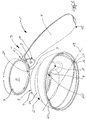
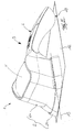
- FIG. 1 shows a stand magnifier 1, which is composed of a magnifying glass 2 and a magnifying glass element 3.
- the magnifying glass element 3 has a handle 4 and a magnifying glass body 5, which is arranged on a handle end 6, on.
- the magnifying element 3 is detachably connected to the magnifier 2 and thus forms a hand magnifier.
- the terms "hand-held magnifier 3" and "magnifying-glass element 3" are used synonymously.
- the detachable connection between the magnifying glass pot 2 and the magnifying glass 3 can be formed by a plurality of attractively coupled magnets 7 in the edge region 8 of the magnifying glass body 5. In the preferred embodiment, three pairs of magnets 7 were used.
- the magnets 7 can also be embedded in the edge region of the socket of the magnifying glass body in a flush manner.
- the detachable connection can also be realized in the form of a snap-latch connection or a combination of a snap-latch connection and a plurality of magnet 7 coupled to one another in an attractive manner.
- the hand-held magnifier 3 is provided with a lighting means 9.
- the lighting means 9 is supplied by means of batteries or rechargeable batteries 10 with voltage. In the case of the use of batteries 10, these can be connected via a charging socket 11 to a power supply unit and charged.
- a power supply of the lamp 9 is directly according to the invention via a network connection.
- the footprint 12 is shown by the reference numeral 12.
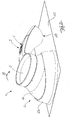
- the stand magnifier 1 according to the invention is in the assembled state of the magnifying glass 3 and magnifying glass 2 with respect to the footprint 12 pivotally.
- the drawing figures 3 and 4 show the two end positions of the pivotable stand magnifier 1.
- the pivot axis 13 extends approximately centrally through the magnifier pot 2 and immediately above the footprint 12th
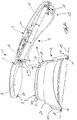
- the magnifying glass pot 2 is formed in two parts, wherein the two movable magnifier pot parts 2a, 2b are mounted to be movable relative to each other and engage substantially light-tight in one another.
- the base surface shape of the magnifying glass pot 2 is round, it is suitable for the shape of the magnifying glass parts 2a, 2b a spherical cap formation.
- the pivot axis 13 is connected by a pin 14 and antidote 15 connection in the each formed pivotable cup parts 2a, 2b formed or defined, see. in particular drawing figure 2.
- the pivoting of the two magnifier pot parts 2a, 2b is in the preferred embodiment by latching elements (not shown), which are arranged at least on a Lupentopfteil 2a, 2b, provided with a grid.
- the magnifying glass pot 2 starting from a parallel position between the footprint 12 and the magnifying glass 5 in at least two directions A, B pivot.
- a recess 18 is provided on the upper edge 17 of the magnifier pot 2, which corresponds to a Ansetz Scheme 19 of the magnifier 3.
- Such a Ansetz Berlin 19 may for example have a recessed edge, which is adapted to the recess 18 of the magnifying glass 2.
- the upper edge 17 has an annular collar 20, which corresponds to a counter area 21 of the magnifying glass 3.
- the handle 4 of the stand magnifier 1 is shaped so that it touches the footprint 12 with its free Griffend Scheme 23, wherein the free end portion Griffend 23 remains over the entire pivotal movement A, B with the footprint 12 in touch. It is expedient to arrange the free end of the handle 23 of the magnifying glass 5 arranged handle 4 abrolltransport in the plane of the footprint 12 or support.
- the arranged at the end of the handle 4 charging socket 11 is arranged such that a in this plugged charging connector (not shown), the rolling movement of the free end of the handle 23 on the footprint 12 is not affected.
- the handle 4 can extend radially outward, it is expedient, the central longitudinal axis (not shown) of the handle 4 to extend parallel to the pivot axis 13.
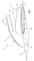
- the drawing figures 5 and 6 relate to a second alternative embodiment in which the magnifying glass pot 2 has a rectangular base surface shape.
- the magnifying glass pot 2 has a rectangular base surface shape.
- the free end of the handle 23 with tilted hand magnifier ( FIG. 5 ) rests on the footprint 12 and in a second position in which the magnifying glass body 5 and the footprint 12 are parallel to each other ( FIG. 6 ), the handle end 23 is arranged above the footprint 12 spaced.
- the pivot axis 13 In the case of the substantially rectangular basic surface shape of the magnifying glass pot 2, it is also possible to allow the pivot axis 13 to extend substantially along the diagonal (not shown) of the rectangular base surface shape and to allow the central longitudinal axis of the handle 4 to run in alignment with the pivot axis 13 in plan view , It is possible that the handle end 23 rests in each pivot position of the magnifier pot 2 on the footprint 12.
- the light source 9 can be actuated via the switch 16.
Landscapes
- Physics & Mathematics (AREA)
- General Physics & Mathematics (AREA)
- Optics & Photonics (AREA)
- Health & Medical Sciences (AREA)
- Ophthalmology & Optometry (AREA)
- General Health & Medical Sciences (AREA)
- Lenses (AREA)
- Investigating Materials By The Use Of Optical Means Adapted For Particular Applications (AREA)
Applications Claiming Priority (2)
| Application Number | Priority Date | Filing Date | Title |
|---|---|---|---|
| DE102007003303A DE102007003303B4 (de) | 2007-01-17 | 2007-01-17 | Standlupe |
| PCT/DE2008/000054 WO2008086780A2 (de) | 2007-01-17 | 2008-01-15 | Standlupe |
Publications (2)
| Publication Number | Publication Date |
|---|---|
| EP2111561A2 EP2111561A2 (de) | 2009-10-28 |
| EP2111561B1 true EP2111561B1 (de) | 2017-06-14 |
Family
ID=39271348
Family Applications (1)
| Application Number | Title | Priority Date | Filing Date |
|---|---|---|---|
| EP08706751.8A Not-in-force EP2111561B1 (de) | 2007-01-17 | 2008-01-15 | Standlupe |
Country Status (7)
| Country | Link |
|---|---|
| US (1) | US8089710B2 (enExample) |
| EP (1) | EP2111561B1 (enExample) |
| JP (1) | JP2010517061A (enExample) |
| KR (1) | KR20090107537A (enExample) |
| CN (1) | CN101646969B (enExample) |
| DE (1) | DE102007003303B4 (enExample) |
| WO (1) | WO2008086780A2 (enExample) |
Families Citing this family (6)
| Publication number | Priority date | Publication date | Assignee | Title |
|---|---|---|---|---|
| DE102010010464B4 (de) * | 2010-03-06 | 2011-11-17 | Bcd-Gmbh | Lesehilfe |
| CN102789051B (zh) * | 2011-05-17 | 2014-10-01 | 东莞长城光学塑胶厂有限公司 | 一种手持放大镜 |
| CN103969821A (zh) * | 2014-04-23 | 2014-08-06 | 东莞市莞龙光电有限责任公司 | 入视角倾斜/可调之放大镜 |
| CN104977709A (zh) * | 2015-08-06 | 2015-10-14 | 江苏省建筑工程质量检测中心有限公司 | 一种微裂纹多倍数观察装置 |
| USD821576S1 (en) * | 2016-03-17 | 2018-06-26 | Anthony Alatriste | Stethoscope accessory |
| US9904059B2 (en) * | 2016-07-08 | 2018-02-27 | Shirley Vetrone | Reading aid |
Citations (1)
| Publication number | Priority date | Publication date | Assignee | Title |
|---|---|---|---|---|
| JPH0659816U (ja) * | 1992-04-22 | 1994-08-19 | 晃 梅原 | ルーペ装置 |
Family Cites Families (22)
| Publication number | Priority date | Publication date | Assignee | Title |
|---|---|---|---|---|
| DE864007C (de) * | 1951-07-25 | 1953-01-22 | Otto Wortmann | Mit einer Landkarte versehene, allseitig drehbare Trommel oder Kugel |
| DE2348567A1 (de) * | 1973-09-27 | 1975-04-17 | Guido Georg Reinert | Fluoreszenzlampe des entladungsroehrentyps mit uv-strahlendem leuchtstoff, sogenannter schwarzlichtleuchtstoffroehre fuer die beobachtung feiner strukturen mittels einer lupe, eines stereomikroskops oder aequivalenter optischer geraete |
| JPS5925509U (ja) * | 1982-08-06 | 1984-02-17 | 株式会社冨士光器製作所 | スタンド付きフラツシユマグニフアイア− |
| DE3427217A1 (de) * | 1984-07-24 | 1986-02-06 | Norbert 2000 Hamburg Eisenbrandt | Standlupe mit indirekter beleuchtung |
| US5087112A (en) * | 1990-07-19 | 1992-02-11 | Designs For Vision, Inc. | Optical magnifier apparatus |
| US5267716A (en) * | 1992-06-03 | 1993-12-07 | Friedman Arthur S | Mount for magnifying lens |
| DE9217484U1 (de) * | 1992-12-22 | 1994-04-21 | Eschenbach Optik GmbH + Co, 90409 Nürnberg | Lesegerät |
| DE9302485U1 (de) * | 1993-02-20 | 1994-06-23 | Eschenbach Optik GmbH + Co, 90409 Nürnberg | Betrachtungsgerät für transparente Objekte |
| DE9412153U1 (de) * | 1994-07-28 | 1994-10-06 | A. Schweizer GmbH Optische Fabrik, 91301 Forchheim | Beleuchtbare Standlupe |
| DE19711645C1 (de) * | 1997-03-20 | 1998-08-20 | Schweizer Gmbh Optische Fabrik | Beleuchtbare Handlupe |
| EP0916984A1 (en) * | 1997-11-15 | 1999-05-19 | Canon Kabushiki Kaisha | Light deflection device and array thereof |
| AU2382801A (en) * | 1999-12-30 | 2001-07-16 | Wayne Birchall | Anterior segment viewing device |
| CN2406262Y (zh) * | 2000-01-10 | 2000-11-15 | 东莞宇宙电子有限公司 | 手柄式无影发光放大镜 |
| CN2408475Y (zh) * | 2000-01-20 | 2000-11-29 | 东莞宇宙电子有限公司 | 冷光源座台式无影发光放大镜 |
| DE20122068U1 (de) * | 2000-03-11 | 2004-02-19 | Linos Photonics Gmbh & Co. Kg | Dermatologie-Handlupe |
| DE10020715B4 (de) | 2000-03-11 | 2004-05-13 | Rodenstock Präzisionsoptik GmbH + Co. KG | Dermatologie-Handlupe |
| DE20023758U1 (de) | 2000-04-26 | 2006-02-02 | A. Schweizer Gmbh Optische Fabrik | Vergrößerndes optisches System, insbesondere vergrößernde optische Sehhilfe |
| US6621646B2 (en) * | 2000-10-26 | 2003-09-16 | Ki-Su Jung | Adjustable table magnifier |
| DE20122490U1 (de) | 2001-04-20 | 2005-11-10 | Eschenbach Optik Gmbh & Co | Sehhilfe (Handfernrohr) |
| US6553626B2 (en) * | 2001-08-27 | 2003-04-29 | Lee Valley Tools, Ltd. | Magnetic hinge |
| US7246927B2 (en) * | 2004-12-07 | 2007-07-24 | Black & Decker Inc. | Fluorescent flashlight |
| US7277240B2 (en) * | 2005-01-28 | 2007-10-02 | Carnevali Jeffrey D | Intermediately mounted magnification apparatus |
-
2007
- 2007-01-17 DE DE102007003303A patent/DE102007003303B4/de active Active
-
2008
- 2008-01-15 US US12/523,581 patent/US8089710B2/en not_active Expired - Fee Related
- 2008-01-15 JP JP2009545815A patent/JP2010517061A/ja active Pending
- 2008-01-15 EP EP08706751.8A patent/EP2111561B1/de not_active Not-in-force
- 2008-01-15 KR KR1020097016724A patent/KR20090107537A/ko not_active Withdrawn
- 2008-01-15 WO PCT/DE2008/000054 patent/WO2008086780A2/de not_active Ceased
- 2008-01-15 CN CN2008800063111A patent/CN101646969B/zh not_active Expired - Fee Related
Patent Citations (1)
| Publication number | Priority date | Publication date | Assignee | Title |
|---|---|---|---|---|
| JPH0659816U (ja) * | 1992-04-22 | 1994-08-19 | 晃 梅原 | ルーペ装置 |
Also Published As
| Publication number | Publication date |
|---|---|
| US8089710B2 (en) | 2012-01-03 |
| WO2008086780A3 (de) | 2008-09-25 |
| KR20090107537A (ko) | 2009-10-13 |
| WO2008086780A2 (de) | 2008-07-24 |
| US20100067125A1 (en) | 2010-03-18 |
| CN101646969A (zh) | 2010-02-10 |
| EP2111561A2 (de) | 2009-10-28 |
| DE102007003303A1 (de) | 2008-07-31 |
| DE102007003303B4 (de) | 2010-04-15 |
| CN101646969B (zh) | 2011-11-16 |
| JP2010517061A (ja) | 2010-05-20 |
Similar Documents
| Publication | Publication Date | Title |
|---|---|---|
| EP2111561B1 (de) | Standlupe | |
| EP1670618B1 (de) | Akkuschrauber | |
| EP1778440B1 (de) | Akkuschrauber | |
| EP1670619B1 (de) | Ladegerät für einen Akkuschrauber | |
| DE10348528B4 (de) | Taschenwerkzeug | |
| DE102011003603B4 (de) | Durchlichtbeleuchtungseinrichtung für ein Mikroskop | |
| CH695370A5 (de) | Funktionsteilerträger | |
| EP2087386A1 (de) | Beleuchtungsvorrichtung | |
| DE69730000T2 (de) | Schnurloses, in jeder Lage wiederaufladbares Telefon | |
| EP1670010A8 (en) | Switch | |
| DE102012216600B4 (de) | Aufsatzkappe für eine Handwerkzeugmaschine | |
| EP2342592B1 (de) | Lichtquelle | |
| DE19933526B4 (de) | Lichtleiter-Steckverbinder für ein endoskopisches System | |
| DE102007024014A1 (de) | Beleuchtungsvorrichtung | |
| DE10020390B4 (de) | Vergrößerndes optisches System, insbesondere vergrößernde optische Sehhilfe | |
| DE102004034887A1 (de) | Mikroskop mit schwenkbarer Haltevorrichtung für optische Komponenten | |
| EP2138763B1 (de) | Strahler und Stromschienensystem mit einem solchen Strahler | |
| DE202009005400U1 (de) | Solarstehleuchte | |
| DE19711645C1 (de) | Beleuchtbare Handlupe | |
| DE202017004833U1 (de) | Schirm, insbesondere Regenschirm | |
| DE102016202613B4 (de) | Handlupe und Handlupensystem | |
| DE102024107871A1 (de) | Halterung für mobile Handgeräte | |
| DE212020000495U1 (de) | Doppelzweck-Lampenschubladengruppenvorrichtung für ein Mikroskop | |
| DE10161865B4 (de) | Mobile brettartige Schreib- und Zeichenunterlage | |
| EP4431785A1 (de) | Haltesystem und verfahren zur lösbaren befestigung eines flachen gegenstands an einem objekt und haltevorrichtung zur verwendung in einem solchen haltesystem |
Legal Events
| Date | Code | Title | Description |
|---|---|---|---|
| PUAI | Public reference made under article 153(3) epc to a published international application that has entered the european phase |
Free format text: ORIGINAL CODE: 0009012 |
|
| 17P | Request for examination filed |
Effective date: 20090806 |
|
| AK | Designated contracting states |
Kind code of ref document: A2 Designated state(s): AT BE BG CH CY CZ DE DK EE ES FI FR GB GR HR HU IE IS IT LI LT LU LV MC MT NL NO PL PT RO SE SI SK TR |
|
| DAX | Request for extension of the european patent (deleted) | ||
| REG | Reference to a national code |
Ref country code: DE Ref legal event code: R079 Ref document number: 502008015385 Country of ref document: DE Free format text: PREVIOUS MAIN CLASS: G02B0025000000 Ipc: G02B0025020000 |
|
| 17Q | First examination report despatched |
Effective date: 20140611 |
|
| RIC1 | Information provided on ipc code assigned before grant |
Ipc: G02B 25/02 20060101AFI20140604BHEP Ipc: G02B 25/00 20060101ALI20140604BHEP Ipc: G02B 27/02 20060101ALI20140604BHEP |
|
| GRAP | Despatch of communication of intention to grant a patent |
Free format text: ORIGINAL CODE: EPIDOSNIGR1 |
|
| INTG | Intention to grant announced |
Effective date: 20161103 |
|
| GRAJ | Information related to disapproval of communication of intention to grant by the applicant or resumption of examination proceedings by the epo deleted |
Free format text: ORIGINAL CODE: EPIDOSDIGR1 |
|
| GRAP | Despatch of communication of intention to grant a patent |
Free format text: ORIGINAL CODE: EPIDOSNIGR1 |
|
| INTC | Intention to grant announced (deleted) | ||
| INTG | Intention to grant announced |
Effective date: 20170109 |
|
| GRAS | Grant fee paid |
Free format text: ORIGINAL CODE: EPIDOSNIGR3 |
|
| GRAA | (expected) grant |
Free format text: ORIGINAL CODE: 0009210 |
|
| AK | Designated contracting states |
Kind code of ref document: B1 Designated state(s): AT BE BG CH CY CZ DE DK EE ES FI FR GB GR HR HU IE IS IT LI LT LU LV MC MT NL NO PL PT RO SE SI SK TR |
|
| REG | Reference to a national code |
Ref country code: GB Ref legal event code: FG4D Free format text: NOT ENGLISH |
|
| REG | Reference to a national code |
Ref country code: CH Ref legal event code: EP Ref country code: AT Ref legal event code: REF Ref document number: 901509 Country of ref document: AT Kind code of ref document: T Effective date: 20170615 |
|
| REG | Reference to a national code |
Ref country code: IE Ref legal event code: FG4D Free format text: LANGUAGE OF EP DOCUMENT: GERMAN |
|
| REG | Reference to a national code |
Ref country code: DE Ref legal event code: R096 Ref document number: 502008015385 Country of ref document: DE |
|
| REG | Reference to a national code |
Ref country code: NL Ref legal event code: MP Effective date: 20170614 |
|
| REG | Reference to a national code |
Ref country code: LT Ref legal event code: MG4D |
|
| PG25 | Lapsed in a contracting state [announced via postgrant information from national office to epo] |
Ref country code: FI Free format text: LAPSE BECAUSE OF FAILURE TO SUBMIT A TRANSLATION OF THE DESCRIPTION OR TO PAY THE FEE WITHIN THE PRESCRIBED TIME-LIMIT Effective date: 20170614 Ref country code: NO Free format text: LAPSE BECAUSE OF FAILURE TO SUBMIT A TRANSLATION OF THE DESCRIPTION OR TO PAY THE FEE WITHIN THE PRESCRIBED TIME-LIMIT Effective date: 20170914 Ref country code: GR Free format text: LAPSE BECAUSE OF FAILURE TO SUBMIT A TRANSLATION OF THE DESCRIPTION OR TO PAY THE FEE WITHIN THE PRESCRIBED TIME-LIMIT Effective date: 20170915 Ref country code: LT Free format text: LAPSE BECAUSE OF FAILURE TO SUBMIT A TRANSLATION OF THE DESCRIPTION OR TO PAY THE FEE WITHIN THE PRESCRIBED TIME-LIMIT Effective date: 20170614 Ref country code: HR Free format text: LAPSE BECAUSE OF FAILURE TO SUBMIT A TRANSLATION OF THE DESCRIPTION OR TO PAY THE FEE WITHIN THE PRESCRIBED TIME-LIMIT Effective date: 20170614 Ref country code: ES Free format text: LAPSE BECAUSE OF FAILURE TO SUBMIT A TRANSLATION OF THE DESCRIPTION OR TO PAY THE FEE WITHIN THE PRESCRIBED TIME-LIMIT Effective date: 20170614 |
|
| PG25 | Lapsed in a contracting state [announced via postgrant information from national office to epo] |
Ref country code: SE Free format text: LAPSE BECAUSE OF FAILURE TO SUBMIT A TRANSLATION OF THE DESCRIPTION OR TO PAY THE FEE WITHIN THE PRESCRIBED TIME-LIMIT Effective date: 20170614 Ref country code: LV Free format text: LAPSE BECAUSE OF FAILURE TO SUBMIT A TRANSLATION OF THE DESCRIPTION OR TO PAY THE FEE WITHIN THE PRESCRIBED TIME-LIMIT Effective date: 20170614 Ref country code: BG Free format text: LAPSE BECAUSE OF FAILURE TO SUBMIT A TRANSLATION OF THE DESCRIPTION OR TO PAY THE FEE WITHIN THE PRESCRIBED TIME-LIMIT Effective date: 20170914 Ref country code: NL Free format text: LAPSE BECAUSE OF FAILURE TO SUBMIT A TRANSLATION OF THE DESCRIPTION OR TO PAY THE FEE WITHIN THE PRESCRIBED TIME-LIMIT Effective date: 20170614 |
|
| REG | Reference to a national code |
Ref country code: FR Ref legal event code: PLFP Year of fee payment: 11 |
|
| PG25 | Lapsed in a contracting state [announced via postgrant information from national office to epo] |
Ref country code: EE Free format text: LAPSE BECAUSE OF FAILURE TO SUBMIT A TRANSLATION OF THE DESCRIPTION OR TO PAY THE FEE WITHIN THE PRESCRIBED TIME-LIMIT Effective date: 20170614 Ref country code: RO Free format text: LAPSE BECAUSE OF FAILURE TO SUBMIT A TRANSLATION OF THE DESCRIPTION OR TO PAY THE FEE WITHIN THE PRESCRIBED TIME-LIMIT Effective date: 20170614 Ref country code: SK Free format text: LAPSE BECAUSE OF FAILURE TO SUBMIT A TRANSLATION OF THE DESCRIPTION OR TO PAY THE FEE WITHIN THE PRESCRIBED TIME-LIMIT Effective date: 20170614 Ref country code: CZ Free format text: LAPSE BECAUSE OF FAILURE TO SUBMIT A TRANSLATION OF THE DESCRIPTION OR TO PAY THE FEE WITHIN THE PRESCRIBED TIME-LIMIT Effective date: 20170614 |
|
| PG25 | Lapsed in a contracting state [announced via postgrant information from national office to epo] |
Ref country code: IT Free format text: LAPSE BECAUSE OF FAILURE TO SUBMIT A TRANSLATION OF THE DESCRIPTION OR TO PAY THE FEE WITHIN THE PRESCRIBED TIME-LIMIT Effective date: 20170614 Ref country code: IS Free format text: LAPSE BECAUSE OF FAILURE TO SUBMIT A TRANSLATION OF THE DESCRIPTION OR TO PAY THE FEE WITHIN THE PRESCRIBED TIME-LIMIT Effective date: 20171014 Ref country code: PL Free format text: LAPSE BECAUSE OF FAILURE TO SUBMIT A TRANSLATION OF THE DESCRIPTION OR TO PAY THE FEE WITHIN THE PRESCRIBED TIME-LIMIT Effective date: 20170614 |
|
| REG | Reference to a national code |
Ref country code: DE Ref legal event code: R097 Ref document number: 502008015385 Country of ref document: DE |
|
| PLBE | No opposition filed within time limit |
Free format text: ORIGINAL CODE: 0009261 |
|
| STAA | Information on the status of an ep patent application or granted ep patent |
Free format text: STATUS: NO OPPOSITION FILED WITHIN TIME LIMIT |
|
| PG25 | Lapsed in a contracting state [announced via postgrant information from national office to epo] |
Ref country code: DK Free format text: LAPSE BECAUSE OF FAILURE TO SUBMIT A TRANSLATION OF THE DESCRIPTION OR TO PAY THE FEE WITHIN THE PRESCRIBED TIME-LIMIT Effective date: 20170614 |
|
| 26N | No opposition filed |
Effective date: 20180315 |
|
| PG25 | Lapsed in a contracting state [announced via postgrant information from national office to epo] |
Ref country code: SI Free format text: LAPSE BECAUSE OF FAILURE TO SUBMIT A TRANSLATION OF THE DESCRIPTION OR TO PAY THE FEE WITHIN THE PRESCRIBED TIME-LIMIT Effective date: 20170614 |
|
| REG | Reference to a national code |
Ref country code: CH Ref legal event code: PL |
|
| PG25 | Lapsed in a contracting state [announced via postgrant information from national office to epo] |
Ref country code: MT Free format text: LAPSE BECAUSE OF FAILURE TO SUBMIT A TRANSLATION OF THE DESCRIPTION OR TO PAY THE FEE WITHIN THE PRESCRIBED TIME-LIMIT Effective date: 20170614 |
|
| PG25 | Lapsed in a contracting state [announced via postgrant information from national office to epo] |
Ref country code: LU Free format text: LAPSE BECAUSE OF NON-PAYMENT OF DUE FEES Effective date: 20180115 |
|
| REG | Reference to a national code |
Ref country code: IE Ref legal event code: MM4A |
|
| REG | Reference to a national code |
Ref country code: BE Ref legal event code: MM Effective date: 20180131 |
|
| PG25 | Lapsed in a contracting state [announced via postgrant information from national office to epo] |
Ref country code: LI Free format text: LAPSE BECAUSE OF NON-PAYMENT OF DUE FEES Effective date: 20180131 Ref country code: CH Free format text: LAPSE BECAUSE OF NON-PAYMENT OF DUE FEES Effective date: 20180131 Ref country code: BE Free format text: LAPSE BECAUSE OF NON-PAYMENT OF DUE FEES Effective date: 20180131 |
|
| PG25 | Lapsed in a contracting state [announced via postgrant information from national office to epo] |
Ref country code: IE Free format text: LAPSE BECAUSE OF NON-PAYMENT OF DUE FEES Effective date: 20180115 |
|
| PG25 | Lapsed in a contracting state [announced via postgrant information from national office to epo] |
Ref country code: MC Free format text: LAPSE BECAUSE OF FAILURE TO SUBMIT A TRANSLATION OF THE DESCRIPTION OR TO PAY THE FEE WITHIN THE PRESCRIBED TIME-LIMIT Effective date: 20170614 |
|
| PG25 | Lapsed in a contracting state [announced via postgrant information from national office to epo] |
Ref country code: TR Free format text: LAPSE BECAUSE OF FAILURE TO SUBMIT A TRANSLATION OF THE DESCRIPTION OR TO PAY THE FEE WITHIN THE PRESCRIBED TIME-LIMIT Effective date: 20170614 |
|
| PG25 | Lapsed in a contracting state [announced via postgrant information from national office to epo] |
Ref country code: HU Free format text: LAPSE BECAUSE OF FAILURE TO SUBMIT A TRANSLATION OF THE DESCRIPTION OR TO PAY THE FEE WITHIN THE PRESCRIBED TIME-LIMIT; INVALID AB INITIO Effective date: 20080115 Ref country code: PT Free format text: LAPSE BECAUSE OF FAILURE TO SUBMIT A TRANSLATION OF THE DESCRIPTION OR TO PAY THE FEE WITHIN THE PRESCRIBED TIME-LIMIT Effective date: 20170614 |
|
| PG25 | Lapsed in a contracting state [announced via postgrant information from national office to epo] |
Ref country code: CY Free format text: LAPSE BECAUSE OF FAILURE TO SUBMIT A TRANSLATION OF THE DESCRIPTION OR TO PAY THE FEE WITHIN THE PRESCRIBED TIME-LIMIT Effective date: 20170614 |
|
| PGFP | Annual fee paid to national office [announced via postgrant information from national office to epo] |
Ref country code: GB Payment date: 20210122 Year of fee payment: 14 |
|
| PGFP | Annual fee paid to national office [announced via postgrant information from national office to epo] |
Ref country code: DE Payment date: 20220127 Year of fee payment: 15 |
|
| PGFP | Annual fee paid to national office [announced via postgrant information from national office to epo] |
Ref country code: FR Payment date: 20220120 Year of fee payment: 15 |
|
| GBPC | Gb: european patent ceased through non-payment of renewal fee |
Effective date: 20220115 |
|
| PG25 | Lapsed in a contracting state [announced via postgrant information from national office to epo] |
Ref country code: GB Free format text: LAPSE BECAUSE OF NON-PAYMENT OF DUE FEES Effective date: 20220115 |
|
| PGFP | Annual fee paid to national office [announced via postgrant information from national office to epo] |
Ref country code: AT Payment date: 20230118 Year of fee payment: 16 |
|
| P01 | Opt-out of the competence of the unified patent court (upc) registered |
Effective date: 20230517 |
|
| REG | Reference to a national code |
Ref country code: DE Ref legal event code: R119 Ref document number: 502008015385 Country of ref document: DE |
|
| PG25 | Lapsed in a contracting state [announced via postgrant information from national office to epo] |
Ref country code: DE Free format text: LAPSE BECAUSE OF NON-PAYMENT OF DUE FEES Effective date: 20230801 |
|
| PG25 | Lapsed in a contracting state [announced via postgrant information from national office to epo] |
Ref country code: FR Free format text: LAPSE BECAUSE OF NON-PAYMENT OF DUE FEES Effective date: 20230131 |
|
| REG | Reference to a national code |
Ref country code: AT Ref legal event code: MM01 Ref document number: 901509 Country of ref document: AT Kind code of ref document: T Effective date: 20240115 |
|
| PG25 | Lapsed in a contracting state [announced via postgrant information from national office to epo] |
Ref country code: AT Free format text: LAPSE BECAUSE OF NON-PAYMENT OF DUE FEES Effective date: 20240115 |
|
| PG25 | Lapsed in a contracting state [announced via postgrant information from national office to epo] |
Ref country code: AT Free format text: LAPSE BECAUSE OF NON-PAYMENT OF DUE FEES Effective date: 20240115 |