EP2110831A2 - Ensemble de boîte de soufflage pour disjoncteur - Google Patents
Ensemble de boîte de soufflage pour disjoncteur Download PDFInfo
- Publication number
- EP2110831A2 EP2110831A2 EP09157488A EP09157488A EP2110831A2 EP 2110831 A2 EP2110831 A2 EP 2110831A2 EP 09157488 A EP09157488 A EP 09157488A EP 09157488 A EP09157488 A EP 09157488A EP 2110831 A2 EP2110831 A2 EP 2110831A2
- Authority
- EP
- European Patent Office
- Prior art keywords
- housing
- arc
- deion
- deion plates
- plates
- Prior art date
- Legal status (The legal status is an assumption and is not a legal conclusion. Google has not performed a legal analysis and makes no representation as to the accuracy of the status listed.)
- Granted
Links
Images


Classifications
-
- H—ELECTRICITY
- H01—ELECTRIC ELEMENTS
- H01H—ELECTRIC SWITCHES; RELAYS; SELECTORS; EMERGENCY PROTECTIVE DEVICES
- H01H9/00—Details of switching devices, not covered by groups H01H1/00 - H01H7/00
- H01H9/30—Means for extinguishing or preventing arc between current-carrying parts
- H01H9/34—Stationary parts for restricting or subdividing the arc, e.g. barrier plate
- H01H9/342—Venting arrangements for arc chutes
-
- H—ELECTRICITY
- H01—ELECTRIC ELEMENTS
- H01H—ELECTRIC SWITCHES; RELAYS; SELECTORS; EMERGENCY PROTECTIVE DEVICES
- H01H9/00—Details of switching devices, not covered by groups H01H1/00 - H01H7/00
- H01H9/30—Means for extinguishing or preventing arc between current-carrying parts
- H01H9/44—Means for extinguishing or preventing arc between current-carrying parts using blow-out magnet
-
- H—ELECTRICITY
- H01—ELECTRIC ELEMENTS
- H01H—ELECTRIC SWITCHES; RELAYS; SELECTORS; EMERGENCY PROTECTIVE DEVICES
- H01H9/00—Details of switching devices, not covered by groups H01H1/00 - H01H7/00
- H01H9/30—Means for extinguishing or preventing arc between current-carrying parts
- H01H9/34—Stationary parts for restricting or subdividing the arc, e.g. barrier plate
- H01H2009/347—Stationary parts for restricting or subdividing the arc, e.g. barrier plate using lids for closing the arc chamber after assembly
-
- H—ELECTRICITY
- H01—ELECTRIC ELEMENTS
- H01H—ELECTRIC SWITCHES; RELAYS; SELECTORS; EMERGENCY PROTECTIVE DEVICES
- H01H9/00—Details of switching devices, not covered by groups H01H1/00 - H01H7/00
- H01H9/30—Means for extinguishing or preventing arc between current-carrying parts
- H01H9/34—Stationary parts for restricting or subdividing the arc, e.g. barrier plate
- H01H9/36—Metal parts
- H01H2009/365—Metal parts using U-shaped plates
Definitions
- the present invention relates to electrical switchgear. More particularly, the present invention relates to an arc chute assembly.
- Circuit breakers and other electrical switching apparatuses typically include a set of stationary electrical contacts and a set of moveable electrical contacts.
- the stationary and moveable contacts are in physical contact with one another when it is desired that the circuit breaker provide electrical current to a load.
- the moveable contacts are moved away from the stationary contacts, thus removing the moveable contacts from physical contact with the stationary contacts and creating a space there between. This may result in the formation of an electrical arc beginning at the time the contacts are separated.
- electrical arcs also known as "arc discharges" are undesirable for a number of reasons.
- they provide a pathway for current to flow through the circuit breaker to a load when it is desired that the load be isolated from such current.
- the electrical arc extending between the contacts often results in vaporization or sublimation of the contact material itself, eventually resulting in destruction or pitting of contacts.
- manufactures of breakers and switching gear have developed mechanisms to facilitate quenching of this undesirable arc discharge.
- early manufactures used a method of immersing the contact material in an oil, or inert gas, while others created a vacuum to quench arcing.
- arc chutes has been a preferred method to quench undesirable arcing.
- U.S. Patent No. 6,703,576 provides an arc chute having a main valve formed by a flexible sheet member that is mounted over a gas opening of the arc chamber structure by extensions on arc plates that form guides received in elongated slots in the ends of the flexible sheet member.
- the force generated by high pressure gas in the arc chamber on the center of the flexible sheet member causes it to bow allowing arc gases to escape laterally as the ends of the flexible sheet member are drawn towards each other.
- U.S. Patent Application US20070062912A1 which comprises an arc chute having two side parallel flanges, a rear wall, and a bottom arcing horn made of conducting material, electrically connected to the stationary contact part.
- the bottom arcing horn is surrounded by a periphery made of gas-generating material.
- the arc chute comprises a stack of separators at least two of which separators comprise a notch, at least one regenerating separator placed parallel to the bottom arcing horn, the at least one separator comprising at least one metallic surface covering at least half of the notches in the longitudinal mid-plane.
- an arc chute assembly comprises a housing having a lateral axis and a quenching portion disposed within the housing.
- the quenching portion comprises at least two deion plates being spaced along the lateral axis of the housing and each having a cut portion wherein the cut portions are staggered along the lateral axis with respect to one another and are configured to mitigate an arc.
- One embodiment of the present invention involves an arc chute assembly which comprises a housing and a quenching portion disposed within the housing.
- the quenching portion comprises at least two laterally spaced deion plates having a cut portion wherein the cut portions are staggered with respect to one another and are configured to mitigate an arc.
- Exemplary advantages afforded by this invention is its easy to assemble modular design, improved structural strength to withstand pressure developed during high short circuit fault levels, its improved arc quenching capability and its improved life span for interruption of rated current.
- a circuit breaker array 100 that may be used with an embodiment of the present invention may comprise known circuit breaker components, e.g., contacts, latches, solenoids, and actuators (all of which are not shown or described herein).
- An arc chute assembly in accordance with one embodiment of the present invention is shown generally at 102.
- the arc chute assembly 102 may be dimensioned to correspond to the breaker aperture 104 and, when inserted, function to mitigate any electrical arc created as contacts move away from one another in a circuit breaker.
- the arc chute assembly may comprise a housing 202, deion plates 208, an insulating member 210, a filter 224 and stability member 214.
- the housing 202 may comprise an insulative and moldable substance such as a polymeric substance and may comprise a generally bifurcated structure resulting in housing members 204 and 206 that may be connected together by fasteners 207 together with a stability member 214 (as described in more detail below).
- any connecting means e.g., screws, nails, paste
- the housing may be constructed with any material that may suitably withstand the inherent heat given off by a breaker assembly while not substantially interfering with a breakers required magnetic properties.
- Each housing member 204 and 206 comprises venting slots 228 which will be described in greater detail below.
- the housing 202 may allow for a modular form that lends itself to drop-down assembly. Therefore, in one particular embodiment, arc chute assembly 200 may be installed into a circuit breaker array 100 ( Figure 1 ) at any time due to its flexible assembly. In case the arc chute 200 is inserted in a circuit breaker in an undesired orientation, the projection 504 on the arc runner plate 502 (see Figure 5 ) will interfere with a corresponding projection on the breaker housing. This will ensure proper alignment of the arc chute 200 and will prevent assembly of arc chute in an improper orientation.
- insulating member 210 may comprise an insulating sheet comprising venting apertures 222.
- the insulating member may be arranged, in turn, to isolate the deion plates 208 from the metallic filter 224 while allowing arc gasses to move outwards through the venting apertures 212.
- the insulating member may be constructed from an electrically nonconductive material, e.g., glass melamine, glass epoxy sheet, polyester based material and may be oriented orthogonally with respect to the deion plates.
- filter 224 may be disposed within the housing and arranged adjacent to the insulating member 216 and orthogonal to the deion plates 208.
- the filter 224 may comprise a perforated sheet metal having a wavy structure, such as a generally sideways S-shape in cross section, and be configured to filter arc products such as hot metal particles.
- the invention may further comprise stability member 214.
- the stability member 214 may be disposed adjacent to the metallic filter 224 inside the housing 202.
- the stability member may comprise, for example, a steel plate and may be oriented orthogonally with respect to the deion plates 208. Although, as shown, the stability member is in the configuration of a plate, it is to be appreciated that stability members may comprise other geometric configurations such rods, pins, and the like may be employed.
- the stability member 214 may be configured to add structural strength to the assembly to withstand pressure that may be developed under high-fault conditions.
- the stability member 214 may be further configured to allow for the arc gases to move outwards though the venting apertures 228, and therefore may further comprise stability member apertures 226.
- the venting slots 228 may be configured to facilitate the movement of arc gases that may develop during circuit breaker function (i.e., when arcs form).
- the venting slots 228 may comprise a plurality of elongated spaces in the top wall of the housing, thereby facilitating arc gases movement up through the deion plates 208, through the insulating member 210 and the stability member 214 and outwardly from the breaker assembly.
- the deion plates 208 may be disposed within the housing 202 and dimensioned to fit into support members 218, which will be discussed in greater detail with reference to Figs 3 and 4 . As shown in Figure 2 , a plurality of deion plates 208 may be laterally spaced through the housing 202. Each deion plate 208 may comprise a mounting slot 203 that is correspondingly configured to engage a projection 303 ( Figure 3 ) of the housing.
- the mounting slot 203 and projection 303 ( Figure 3 ) may be generally rectangular in cross section.
- Each deion plate 208 may further comprise a cut portion 220.
- the cut portion 220 may be generally arcuate in shape having a notch and may be configured to allow contacts to move therethrough. While the deion plates may be substantially parallel with respect to one another, the cut portion of each deion plate may be staggered with respect to one another, which will be discussed in greater detail below with respect to Figure 3 . By “staggered” it is meant that the cut portions are arranged on or as if on alternating sides of a centerline proceeding down an axis (a) of housing member 206.
- deion plates 208 and the cut portions 220 with respect thereto provides for optimal quenching of an electrical arc by giving effective magnetic pull to the arc column. This arrangement also has been found to quench arcs across various fault levels and system voltages.
- the deion plates 208 may be composed of ferromagnetic material such as steel alloys.
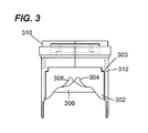
- FIG. 3 there is shown another view which best illustrates a staggered arrangement of cut portions of a number of deion plates in accordance with an exemplary embodiment of the present invention.
- the first deion plate 302 comprises cut portion 304 and the second deion plate 306 comprises cut portion 308.
- the deion plates are configured laterally with respect to one another, and are attached to the housing 310 via support members 312.
- the cut portion 304 of the first deion plate 302 is staggered with respect to the cut portion 308 of the second deion plate 306. It is to be appreciated that this alignment may continue as more deion plates are added to the assembly.
- Housing member 400 comprises a support member 402, extended flange 406 and venting slots 408.
- the support member 402 may comprise angular array of support members 410 and a parallel support members 412.
- the support members 410 and 412 may be dimensioned to retain a plurality of deion plates in a lateral arrangement.
- the angular array of support members 410 may be dimensioned to correspond to a corner of a deion plate, while the parallel support members 410 may be dimensioned to correspond with a bottom portion of a deion plate.
- the venting slots 408 may be formed by tabs 418. Because only a portion of the chute assembly is shown, it is to be appreciated that analogous tabs on a second portion of another housing member of the assembly (not shown) may combine to form the venting apertures.
- the tabs 418 as shown, have an angled profile 416 to act as a nozzle thereby more readily facilitating the escape of arc gases.
- the flange 406 may be an extended section of a side of the housing.
- the flange 406 may be configured to protect the circuit breaker housing from corrosion, pitting and breakdown during arcing.
- the extended flange 406 may comprise rib pieces 420 which maybe configured to increase over surface dielectric capacity due to increased over surface distance.
- the flange may also comprise mounting bores 422 for mounting ablative liners, which helps to quench the arc efficiently.
- FIG. 5 a view best illustrating the arc runner 502 employed at one end of an array of deion plates 506 having a protrusion 504 is shown at 500.
- deion plates 506 and flange 508 are also shown.
- the arc runner 502 may be configured to guide the electrical arc between movable contact and the deion plates.
- the protrusion 504 is configured to prevent reverse assembly in the circuit breaker.
Applications Claiming Priority (1)
| Application Number | Priority Date | Filing Date | Title |
|---|---|---|---|
| US12/103,008 US7705263B2 (en) | 2008-04-15 | 2008-04-15 | Arc chute assembly for a circuit breaker |
Publications (3)
| Publication Number | Publication Date |
|---|---|
| EP2110831A2 true EP2110831A2 (fr) | 2009-10-21 |
| EP2110831A3 EP2110831A3 (fr) | 2012-08-29 |
| EP2110831B1 EP2110831B1 (fr) | 2016-03-23 |
Family
ID=40911906
Family Applications (1)
| Application Number | Title | Priority Date | Filing Date |
|---|---|---|---|
| EP09157488.9A Active EP2110831B1 (fr) | 2008-04-15 | 2009-04-07 | Ensemble de boîte de soufflage pour disjoncteur |
Country Status (4)
| Country | Link |
|---|---|
| US (1) | US7705263B2 (fr) |
| EP (1) | EP2110831B1 (fr) |
| JP (1) | JP5468808B2 (fr) |
| CN (1) | CN101562083B (fr) |
Cited By (4)
| Publication number | Priority date | Publication date | Assignee | Title |
|---|---|---|---|---|
| EP2637187A1 (fr) * | 2012-03-07 | 2013-09-11 | Siemens Aktiengesellschaft | Fixation de tôles d'extinction dans le pôle de commutation d'un disjoncteur |
| US9035664B2 (en) | 2010-05-11 | 2015-05-19 | Siemens Aktiengesellschaft | Device and method for measuring currents in a bearing |
| WO2015073136A1 (fr) * | 2013-11-15 | 2015-05-21 | Eaton Corporation | Dispositif déflecteur d'arc |
| CN108735536A (zh) * | 2017-04-14 | 2018-11-02 | 施耐德电器工业公司 | 灭弧气体过滤装置和包括其的电流开关设备 |
Families Citing this family (26)
| Publication number | Priority date | Publication date | Assignee | Title |
|---|---|---|---|---|
| US8563888B2 (en) * | 2008-06-11 | 2013-10-22 | General Electric Company | Arc containment device and method |
| CA2796548C (fr) * | 2010-04-16 | 2018-09-11 | Abb Technology Ag | Chambre d'extinction d'arc pour disjoncteur, disjoncteur et procede d'assemblage d'une chambre d'extinction d'arc |
| EP2583293B1 (fr) * | 2010-06-18 | 2017-12-20 | DSM IP Assets B.V. | Disjoncteur |
| US20130112657A1 (en) * | 2010-07-08 | 2013-05-09 | Larsen & Toubro Limited | Arc chamber assembly for use in moulded case circuit breakers |
| US9251980B2 (en) | 2011-01-14 | 2016-02-02 | General Electric Company | Apparatus for interrupting current |
| CN102768925B (zh) * | 2011-05-06 | 2015-02-04 | 北京人民电器厂有限公司 | 断路器用灭弧室 |
| JP5599757B2 (ja) * | 2011-05-19 | 2014-10-01 | 株式会社日立製作所 | 電力変換装置 |
| EP2650893A1 (fr) * | 2012-04-12 | 2013-10-16 | ABB Oy | Appareil de commutation de courant électrique |
| JP2014049300A (ja) * | 2012-08-31 | 2014-03-17 | Toyoda Gosei Co Ltd | 導通遮断装置 |
| EP2965337B1 (fr) * | 2013-03-06 | 2017-04-19 | Eaton Electrical IP GmbH & Co. KG | Pile de plaques pour un dispositif de refroidissement dans des appareils d'installation |
| US9040864B2 (en) * | 2013-05-27 | 2015-05-26 | Asco Power Technologies, L.P. | Profiled arc splitter plate |
| DE102014001730A1 (de) * | 2014-02-08 | 2015-08-13 | Ellenberger & Poensgen Gmbh | Schaltsystem |
| US9349560B2 (en) | 2014-02-20 | 2016-05-24 | General Electric Company | Limiter type air circuit breaker with blow open arrangement |
| US20150270075A1 (en) * | 2014-03-21 | 2015-09-24 | General Electric Company | Modular gas exhaust assembly for a circuit breaker |
| JP6214477B2 (ja) * | 2014-06-20 | 2017-10-18 | 三菱電機株式会社 | 回路遮断器 |
| CN104091734B (zh) * | 2014-07-16 | 2016-04-13 | 德力西电气有限公司 | 一种断路器的灭弧装置 |
| CN104392858A (zh) * | 2014-11-28 | 2015-03-04 | 德力西电气有限公司 | 灭弧室消游离装置及配置该装置的断路器灭弧室 |
| US10134537B2 (en) * | 2015-02-17 | 2018-11-20 | Abb Schweiz Ag | Filter assembly for a circuit breaker arc chamber |
| CN105609388A (zh) * | 2016-03-11 | 2016-05-25 | 天津市百利电气有限公司 | 具有消游离灭弧装置的低压断路器 |
| FR3049386B1 (fr) * | 2016-03-24 | 2018-04-20 | Schneider Electric Industries Sas | Appareil electrique de coupure d'un courant electrique dans l'air comportant un dispositif de filtrage des gaz de coupure ameliore |
| CN106252127B (zh) * | 2016-09-30 | 2018-10-02 | 江苏洛凯机电股份有限公司 | 低压万能式断路器灭弧室 |
| GB2577635B (en) * | 2017-06-17 | 2020-08-19 | Shenzhen Airuixing Ind Design Co Ltd | Arc quenching plate and arc quenching unit with such arc quenching plate and switching device with such arc quenching unit |
| FR3069699B1 (fr) * | 2017-07-26 | 2019-09-06 | Schneider Electric Industries Sas | Dispositif de filtrage de gaz de coupure et appareil de coupure d'un courant electrique comprenant un tel dispositif de filtrage |
| EP3782179A1 (fr) * | 2018-04-19 | 2021-02-24 | ABB S.p.A. | Chambre à arc pour dispositif de commutation basse tension |
| US11177089B2 (en) * | 2019-12-20 | 2021-11-16 | Gong Zhu | Switching device |
| US10957504B1 (en) * | 2019-12-30 | 2021-03-23 | Schneider Electric USA, Inc. | Arc chute for circuit protective devices |
Citations (2)
| Publication number | Priority date | Publication date | Assignee | Title |
|---|---|---|---|---|
| US6703576B1 (en) | 2003-02-13 | 2004-03-09 | Eaton Corporation | Arc chute with valve and electric power switch incorporating same |
| US20070062912A1 (en) | 2005-09-16 | 2007-03-22 | Schneider Electric Industries Sas | Switchgear device comprising an arc chute of reduced size |
Family Cites Families (15)
| Publication number | Priority date | Publication date | Assignee | Title |
|---|---|---|---|---|
| US3005892A (en) * | 1957-03-19 | 1961-10-24 | Ite Circuit Breaker Ltd | Arc chute design for circuit breakers |
| US3202790A (en) * | 1960-08-15 | 1965-08-24 | Allis Chalmers Mfg Co | Barrier arrangement for arc chute which stretches arcs in both vertical and horizontal planes |
| BE635433A (fr) * | 1962-07-27 | |||
| US3374332A (en) * | 1965-07-16 | 1968-03-19 | Square D Co | Arc chute for a circuit breaker |
| US3621169A (en) * | 1970-04-20 | 1971-11-16 | Gen Electric | Electric circuit interrupter with novel arc gas discharge muffle assembly |
| US3728503A (en) * | 1971-01-22 | 1973-04-17 | Ite Imperial Corp | Shock-proof arc chute for high voltage circuit breaker with metallic arc plates having off-set lines of openings |
| US4950852A (en) * | 1989-04-03 | 1990-08-21 | General Electric Company | Electric circuit breaker arc chute composition |
| US4963849A (en) * | 1989-04-28 | 1990-10-16 | General Electric Company | Compact current limiting circuit breaker |
| FR2778788B1 (fr) * | 1998-05-12 | 2000-07-13 | Schneider Electric Ind Sa | Disjoncteur dont une phase au moins est constituee par plusieurs compartiments polaires connectes en parallele |
| JP2000030596A (ja) * | 1998-07-13 | 2000-01-28 | Toshiba Fa Syst Eng Corp | 消孤装置 |
| US7176771B2 (en) * | 2001-08-24 | 2007-02-13 | Square D Company | Circuit breaker filter assembly |
| US6977354B1 (en) * | 2004-11-03 | 2005-12-20 | Eaton Corporation | Arc hood and power distribution system including the same |
| US7034242B1 (en) * | 2004-11-09 | 2006-04-25 | Eaton Corporation | Arc chute and circuit interrupter employing the same |
| CN2932596Y (zh) * | 2006-07-31 | 2007-08-08 | 大全集团有限公司 | 断路器触头隔弧板 |
| US7488915B2 (en) * | 2006-09-20 | 2009-02-10 | Eaton Corporation | ARC baffle, and ARC chute assembly and electrical switching apparatus employing the same |
-
2008
- 2008-04-15 US US12/103,008 patent/US7705263B2/en active Active
-
2009
- 2009-04-07 EP EP09157488.9A patent/EP2110831B1/fr active Active
- 2009-04-13 JP JP2009096565A patent/JP5468808B2/ja active Active
- 2009-04-15 CN CN200910135179.0A patent/CN101562083B/zh active Active
Patent Citations (2)
| Publication number | Priority date | Publication date | Assignee | Title |
|---|---|---|---|---|
| US6703576B1 (en) | 2003-02-13 | 2004-03-09 | Eaton Corporation | Arc chute with valve and electric power switch incorporating same |
| US20070062912A1 (en) | 2005-09-16 | 2007-03-22 | Schneider Electric Industries Sas | Switchgear device comprising an arc chute of reduced size |
Cited By (8)
| Publication number | Priority date | Publication date | Assignee | Title |
|---|---|---|---|---|
| US9035664B2 (en) | 2010-05-11 | 2015-05-19 | Siemens Aktiengesellschaft | Device and method for measuring currents in a bearing |
| EP2637187A1 (fr) * | 2012-03-07 | 2013-09-11 | Siemens Aktiengesellschaft | Fixation de tôles d'extinction dans le pôle de commutation d'un disjoncteur |
| CN103311021A (zh) * | 2012-03-07 | 2013-09-18 | 西门子公司 | 隔弧板在功率开关的开关极中的固定 |
| US9123481B2 (en) | 2012-03-07 | 2015-09-01 | Siemens Aktiengesellschaft | Mounting of splitter plates in the switch pole of a circuit breaker |
| CN103311021B (zh) * | 2012-03-07 | 2017-11-21 | 西门子公司 | 隔弧板在功率开关的开关极中的固定 |
| WO2015073136A1 (fr) * | 2013-11-15 | 2015-05-21 | Eaton Corporation | Dispositif déflecteur d'arc |
| US9153399B2 (en) | 2013-11-15 | 2015-10-06 | Eaton Corporation | ARC baffling device |
| CN108735536A (zh) * | 2017-04-14 | 2018-11-02 | 施耐德电器工业公司 | 灭弧气体过滤装置和包括其的电流开关设备 |
Also Published As
| Publication number | Publication date |
|---|---|
| CN101562083B (zh) | 2014-09-10 |
| JP5468808B2 (ja) | 2014-04-09 |
| JP2009259824A (ja) | 2009-11-05 |
| US7705263B2 (en) | 2010-04-27 |
| CN101562083A (zh) | 2009-10-21 |
| EP2110831A3 (fr) | 2012-08-29 |
| US20090255906A1 (en) | 2009-10-15 |
| EP2110831B1 (fr) | 2016-03-23 |
Similar Documents
| Publication | Publication Date | Title |
|---|---|---|
| EP2110831B1 (fr) | Ensemble de boîte de soufflage pour disjoncteur | |
| EP1655752B1 (fr) | Boite de soufflage et contacteur electromagnetique avec une telle boite de soufflage | |
| EP2064718B1 (fr) | Isolateur d'isolation gazeuse, et ensemble boîte de soufflage et dispositif de commutation électrique l'utilisant | |
| EP1655751A2 (fr) | Couvercle de chambre d'extinction d'arc électrique et système de distribution incorporant ledit couvercle | |
| US7812276B2 (en) | Electrical switching apparatus, and arc chute and arc member therefor | |
| US20170309426A1 (en) | Electric arc-control device | |
| US9697968B2 (en) | Electrical circuit breaker | |
| EP2048678B1 (fr) | Ensemble d'isolant gazogène et ensemble de conducteur et appareil de commutation électrique utilisant la même chose | |
| US9330861B2 (en) | Arc chute assembly for an automatic transfer switch system and methods of assembling the same | |
| EP4333013A1 (fr) | Unité d'extinction d'arc et disjoncteur à air la comprenant | |
| KR20090109503A (ko) | 회로 차단기용 아크 슈트 조립체 | |
| CN115763182A (zh) | 一种灭弧模块 | |
| US4011425A (en) | Arc chute extension for increased interruption rating | |
| CN113168984B (zh) | 分离板、灭弧室和开关设备 | |
| EP0048171A1 (fr) | Dispositifs d'extinction d'arc | |
| JP2006012540A (ja) | 回路遮断器 | |
| WO1992016957A1 (fr) | Commande d'arcs electriques |
Legal Events
| Date | Code | Title | Description |
|---|---|---|---|
| PUAI | Public reference made under article 153(3) epc to a published international application that has entered the european phase |
Free format text: ORIGINAL CODE: 0009012 |
|
| AK | Designated contracting states |
Kind code of ref document: A2 Designated state(s): AT BE BG CH CY CZ DE DK EE ES FI FR GB GR HR HU IE IS IT LI LT LU LV MC MK MT NL NO PL PT RO SE SI SK TR |
|
| PUAL | Search report despatched |
Free format text: ORIGINAL CODE: 0009013 |
|
| AK | Designated contracting states |
Kind code of ref document: A3 Designated state(s): AT BE BG CH CY CZ DE DK EE ES FI FR GB GR HR HU IE IS IT LI LT LU LV MC MK MT NL NO PL PT RO SE SI SK TR |
|
| AX | Request for extension of the european patent |
Extension state: AL BA RS |
|
| RIC1 | Information provided on ipc code assigned before grant |
Ipc: H01H 9/44 20060101ALI20120720BHEP Ipc: H01H 9/34 20060101AFI20120720BHEP |
|
| 17P | Request for examination filed |
Effective date: 20130228 |
|
| GRAP | Despatch of communication of intention to grant a patent |
Free format text: ORIGINAL CODE: EPIDOSNIGR1 |
|
| INTG | Intention to grant announced |
Effective date: 20151023 |
|
| GRAS | Grant fee paid |
Free format text: ORIGINAL CODE: EPIDOSNIGR3 |
|
| GRAA | (expected) grant |
Free format text: ORIGINAL CODE: 0009210 |
|
| AK | Designated contracting states |
Kind code of ref document: B1 Designated state(s): AT BE BG CH CY CZ DE DK EE ES FI FR GB GR HR HU IE IS IT LI LT LU LV MC MK MT NL NO PL PT RO SE SI SK TR |
|
| REG | Reference to a national code |
Ref country code: GB Ref legal event code: FG4D |
|
| REG | Reference to a national code |
Ref country code: CH Ref legal event code: EP |
|
| REG | Reference to a national code |
Ref country code: AT Ref legal event code: REF Ref document number: 783862 Country of ref document: AT Kind code of ref document: T Effective date: 20160415 |
|
| REG | Reference to a national code |
Ref country code: IE Ref legal event code: FG4D |
|
| REG | Reference to a national code |
Ref country code: DE Ref legal event code: R096 Ref document number: 602009036942 Country of ref document: DE |
|
| REG | Reference to a national code |
Ref country code: LT Ref legal event code: MG4D |
|
| REG | Reference to a national code |
Ref country code: NL Ref legal event code: MP Effective date: 20160323 |
|
| PG25 | Lapsed in a contracting state [announced via postgrant information from national office to epo] |
Ref country code: NO Free format text: LAPSE BECAUSE OF FAILURE TO SUBMIT A TRANSLATION OF THE DESCRIPTION OR TO PAY THE FEE WITHIN THE PRESCRIBED TIME-LIMIT Effective date: 20160623 Ref country code: GR Free format text: LAPSE BECAUSE OF FAILURE TO SUBMIT A TRANSLATION OF THE DESCRIPTION OR TO PAY THE FEE WITHIN THE PRESCRIBED TIME-LIMIT Effective date: 20160624 Ref country code: FI Free format text: LAPSE BECAUSE OF FAILURE TO SUBMIT A TRANSLATION OF THE DESCRIPTION OR TO PAY THE FEE WITHIN THE PRESCRIBED TIME-LIMIT Effective date: 20160323 |
|
| REG | Reference to a national code |
Ref country code: AT Ref legal event code: MK05 Ref document number: 783862 Country of ref document: AT Kind code of ref document: T Effective date: 20160323 |
|
| PG25 | Lapsed in a contracting state [announced via postgrant information from national office to epo] |
Ref country code: LV Free format text: LAPSE BECAUSE OF FAILURE TO SUBMIT A TRANSLATION OF THE DESCRIPTION OR TO PAY THE FEE WITHIN THE PRESCRIBED TIME-LIMIT Effective date: 20160323 Ref country code: NL Free format text: LAPSE BECAUSE OF FAILURE TO SUBMIT A TRANSLATION OF THE DESCRIPTION OR TO PAY THE FEE WITHIN THE PRESCRIBED TIME-LIMIT Effective date: 20160323 Ref country code: LT Free format text: LAPSE BECAUSE OF FAILURE TO SUBMIT A TRANSLATION OF THE DESCRIPTION OR TO PAY THE FEE WITHIN THE PRESCRIBED TIME-LIMIT Effective date: 20160323 Ref country code: SE Free format text: LAPSE BECAUSE OF FAILURE TO SUBMIT A TRANSLATION OF THE DESCRIPTION OR TO PAY THE FEE WITHIN THE PRESCRIBED TIME-LIMIT Effective date: 20160323 Ref country code: BE Free format text: LAPSE BECAUSE OF NON-PAYMENT OF DUE FEES Effective date: 20160430 |
|
| PG25 | Lapsed in a contracting state [announced via postgrant information from national office to epo] |
Ref country code: PL Free format text: LAPSE BECAUSE OF FAILURE TO SUBMIT A TRANSLATION OF THE DESCRIPTION OR TO PAY THE FEE WITHIN THE PRESCRIBED TIME-LIMIT Effective date: 20160323 Ref country code: IS Free format text: LAPSE BECAUSE OF FAILURE TO SUBMIT A TRANSLATION OF THE DESCRIPTION OR TO PAY THE FEE WITHIN THE PRESCRIBED TIME-LIMIT Effective date: 20160723 Ref country code: EE Free format text: LAPSE BECAUSE OF FAILURE TO SUBMIT A TRANSLATION OF THE DESCRIPTION OR TO PAY THE FEE WITHIN THE PRESCRIBED TIME-LIMIT Effective date: 20160323 |
|
| PG25 | Lapsed in a contracting state [announced via postgrant information from national office to epo] |
Ref country code: SK Free format text: LAPSE BECAUSE OF FAILURE TO SUBMIT A TRANSLATION OF THE DESCRIPTION OR TO PAY THE FEE WITHIN THE PRESCRIBED TIME-LIMIT Effective date: 20160323 Ref country code: PT Free format text: LAPSE BECAUSE OF FAILURE TO SUBMIT A TRANSLATION OF THE DESCRIPTION OR TO PAY THE FEE WITHIN THE PRESCRIBED TIME-LIMIT Effective date: 20160725 Ref country code: AT Free format text: LAPSE BECAUSE OF FAILURE TO SUBMIT A TRANSLATION OF THE DESCRIPTION OR TO PAY THE FEE WITHIN THE PRESCRIBED TIME-LIMIT Effective date: 20160323 Ref country code: RO Free format text: LAPSE BECAUSE OF FAILURE TO SUBMIT A TRANSLATION OF THE DESCRIPTION OR TO PAY THE FEE WITHIN THE PRESCRIBED TIME-LIMIT Effective date: 20160323 Ref country code: ES Free format text: LAPSE BECAUSE OF FAILURE TO SUBMIT A TRANSLATION OF THE DESCRIPTION OR TO PAY THE FEE WITHIN THE PRESCRIBED TIME-LIMIT Effective date: 20160323 Ref country code: CZ Free format text: LAPSE BECAUSE OF FAILURE TO SUBMIT A TRANSLATION OF THE DESCRIPTION OR TO PAY THE FEE WITHIN THE PRESCRIBED TIME-LIMIT Effective date: 20160323 |
|
| REG | Reference to a national code |
Ref country code: CH Ref legal event code: PL |
|
| PG25 | Lapsed in a contracting state [announced via postgrant information from national office to epo] |
Ref country code: IT Free format text: LAPSE BECAUSE OF FAILURE TO SUBMIT A TRANSLATION OF THE DESCRIPTION OR TO PAY THE FEE WITHIN THE PRESCRIBED TIME-LIMIT Effective date: 20160323 Ref country code: BE Free format text: LAPSE BECAUSE OF FAILURE TO SUBMIT A TRANSLATION OF THE DESCRIPTION OR TO PAY THE FEE WITHIN THE PRESCRIBED TIME-LIMIT Effective date: 20160323 |
|
| REG | Reference to a national code |
Ref country code: DE Ref legal event code: R097 Ref document number: 602009036942 Country of ref document: DE |
|
| REG | Reference to a national code |
Ref country code: IE Ref legal event code: MM4A |
|
| PLBE | No opposition filed within time limit |
Free format text: ORIGINAL CODE: 0009261 |
|
| REG | Reference to a national code |
Ref country code: FR Ref legal event code: ST Effective date: 20161230 |
|
| STAA | Information on the status of an ep patent application or granted ep patent |
Free format text: STATUS: NO OPPOSITION FILED WITHIN TIME LIMIT |
|
| PG25 | Lapsed in a contracting state [announced via postgrant information from national office to epo] |
Ref country code: CH Free format text: LAPSE BECAUSE OF NON-PAYMENT OF DUE FEES Effective date: 20160430 Ref country code: FR Free format text: LAPSE BECAUSE OF NON-PAYMENT OF DUE FEES Effective date: 20160523 Ref country code: LI Free format text: LAPSE BECAUSE OF NON-PAYMENT OF DUE FEES Effective date: 20160430 Ref country code: DK Free format text: LAPSE BECAUSE OF FAILURE TO SUBMIT A TRANSLATION OF THE DESCRIPTION OR TO PAY THE FEE WITHIN THE PRESCRIBED TIME-LIMIT Effective date: 20160323 |
|
| PG25 | Lapsed in a contracting state [announced via postgrant information from national office to epo] |
Ref country code: BG Free format text: LAPSE BECAUSE OF FAILURE TO SUBMIT A TRANSLATION OF THE DESCRIPTION OR TO PAY THE FEE WITHIN THE PRESCRIBED TIME-LIMIT Effective date: 20160623 |
|
| 26N | No opposition filed |
Effective date: 20170102 |
|
| GBPC | Gb: european patent ceased through non-payment of renewal fee |
Effective date: 20160623 |
|
| PG25 | Lapsed in a contracting state [announced via postgrant information from national office to epo] |
Ref country code: GB Free format text: LAPSE BECAUSE OF NON-PAYMENT OF DUE FEES Effective date: 20160623 Ref country code: IE Free format text: LAPSE BECAUSE OF NON-PAYMENT OF DUE FEES Effective date: 20160407 Ref country code: SI Free format text: LAPSE BECAUSE OF FAILURE TO SUBMIT A TRANSLATION OF THE DESCRIPTION OR TO PAY THE FEE WITHIN THE PRESCRIBED TIME-LIMIT Effective date: 20160323 |
|
| PG25 | Lapsed in a contracting state [announced via postgrant information from national office to epo] |
Ref country code: HU Free format text: LAPSE BECAUSE OF FAILURE TO SUBMIT A TRANSLATION OF THE DESCRIPTION OR TO PAY THE FEE WITHIN THE PRESCRIBED TIME-LIMIT; INVALID AB INITIO Effective date: 20090407 Ref country code: CY Free format text: LAPSE BECAUSE OF FAILURE TO SUBMIT A TRANSLATION OF THE DESCRIPTION OR TO PAY THE FEE WITHIN THE PRESCRIBED TIME-LIMIT Effective date: 20160323 |
|
| PG25 | Lapsed in a contracting state [announced via postgrant information from national office to epo] |
Ref country code: MK Free format text: LAPSE BECAUSE OF FAILURE TO SUBMIT A TRANSLATION OF THE DESCRIPTION OR TO PAY THE FEE WITHIN THE PRESCRIBED TIME-LIMIT Effective date: 20160323 Ref country code: TR Free format text: LAPSE BECAUSE OF FAILURE TO SUBMIT A TRANSLATION OF THE DESCRIPTION OR TO PAY THE FEE WITHIN THE PRESCRIBED TIME-LIMIT Effective date: 20160323 Ref country code: LU Free format text: LAPSE BECAUSE OF NON-PAYMENT OF DUE FEES Effective date: 20160407 Ref country code: HR Free format text: LAPSE BECAUSE OF FAILURE TO SUBMIT A TRANSLATION OF THE DESCRIPTION OR TO PAY THE FEE WITHIN THE PRESCRIBED TIME-LIMIT Effective date: 20160323 Ref country code: MT Free format text: LAPSE BECAUSE OF NON-PAYMENT OF DUE FEES Effective date: 20160430 Ref country code: MC Free format text: LAPSE BECAUSE OF FAILURE TO SUBMIT A TRANSLATION OF THE DESCRIPTION OR TO PAY THE FEE WITHIN THE PRESCRIBED TIME-LIMIT Effective date: 20160323 |
|
| REG | Reference to a national code |
Ref country code: DE Ref legal event code: R081 Ref document number: 602009036942 Country of ref document: DE Owner name: ABB S.P.A., IT Free format text: FORMER OWNER: GENERAL ELECTRIC COMPANY, SCHENECTADY, NY, US Ref country code: DE Ref legal event code: R081 Ref document number: 602009036942 Country of ref document: DE Owner name: ABB SCHWEIZ AG, CH Free format text: FORMER OWNER: GENERAL ELECTRIC COMPANY, SCHENECTADY, N.Y., US Ref country code: DE Ref legal event code: R081 Ref document number: 602009036942 Country of ref document: DE Owner name: ABB SCHWEIZ AG, CH Free format text: FORMER OWNER: GENERAL ELECTRIC COMPANY, SCHENECTADY, NY, US |
|
| REG | Reference to a national code |
Ref country code: DE Ref legal event code: R081 Ref document number: 602009036942 Country of ref document: DE Owner name: ABB S.P.A., IT Free format text: FORMER OWNER: ABB SCHWEIZ AG, BADEN, CH Ref country code: DE Ref legal event code: R082 Ref document number: 602009036942 Country of ref document: DE Representative=s name: DENNEMEYER & ASSOCIATES S.A., DE |
|
| PGFP | Annual fee paid to national office [announced via postgrant information from national office to epo] |
Ref country code: DE Payment date: 20230420 Year of fee payment: 15 |