EP4333013A1 - Unité d'extinction d'arc et disjoncteur à air la comprenant - Google Patents
Unité d'extinction d'arc et disjoncteur à air la comprenant Download PDFInfo
- Publication number
- EP4333013A1 EP4333013A1 EP22796052.3A EP22796052A EP4333013A1 EP 4333013 A1 EP4333013 A1 EP 4333013A1 EP 22796052 A EP22796052 A EP 22796052A EP 4333013 A1 EP4333013 A1 EP 4333013A1
- Authority
- EP
- European Patent Office
- Prior art keywords
- arc
- protrusion
- arc extinguishing
- extinguishing unit
- grid
- Prior art date
- Legal status (The legal status is an assumption and is not a legal conclusion. Google has not performed a legal analysis and makes no representation as to the accuracy of the status listed.)
- Pending
Links
- 239000000463 material Substances 0.000 claims abstract description 38
- 238000009413 insulation Methods 0.000 claims description 84
- 125000006850 spacer group Chemical group 0.000 claims description 22
- 230000008878 coupling Effects 0.000 claims description 14
- 238000010168 coupling process Methods 0.000 claims description 14
- 238000005859 coupling reaction Methods 0.000 claims description 14
- 238000012856 packing Methods 0.000 claims description 7
- 229920000728 polyester Polymers 0.000 claims description 6
- 239000002131 composite material Substances 0.000 claims description 5
- 230000000903 blocking effect Effects 0.000 claims description 3
- 239000003365 glass fiber Substances 0.000 abstract description 3
- 230000004308 accommodation Effects 0.000 description 13
- 230000006378 damage Effects 0.000 description 10
- XEEYBQQBJWHFJM-UHFFFAOYSA-N Iron Chemical compound [Fe] XEEYBQQBJWHFJM-UHFFFAOYSA-N 0.000 description 7
- 230000007246 mechanism Effects 0.000 description 7
- 239000010949 copper Substances 0.000 description 5
- RYGMFSIKBFXOCR-UHFFFAOYSA-N Copper Chemical compound [Cu] RYGMFSIKBFXOCR-UHFFFAOYSA-N 0.000 description 4
- 239000000956 alloy Substances 0.000 description 4
- 229910052802 copper Inorganic materials 0.000 description 4
- 239000012535 impurity Substances 0.000 description 4
- 238000000034 method Methods 0.000 description 4
- 238000000926 separation method Methods 0.000 description 4
- 239000007789 gas Substances 0.000 description 3
- 239000003779 heat-resistant material Substances 0.000 description 3
- 229910052742 iron Inorganic materials 0.000 description 3
- 230000008569 process Effects 0.000 description 3
- 229910045601 alloy Inorganic materials 0.000 description 2
- 230000008859 change Effects 0.000 description 2
- 239000004020 conductor Substances 0.000 description 2
- 230000000694 effects Effects 0.000 description 2
- 239000004593 Epoxy Substances 0.000 description 1
- 230000018199 S phase Effects 0.000 description 1
- 208000027418 Wounds and injury Diseases 0.000 description 1
- 230000002159 abnormal effect Effects 0.000 description 1
- 230000015572 biosynthetic process Effects 0.000 description 1
- 229910010293 ceramic material Inorganic materials 0.000 description 1
- 238000007599 discharging Methods 0.000 description 1
- 238000010891 electric arc Methods 0.000 description 1
- 239000011521 glass Substances 0.000 description 1
- 208000014674 injury Diseases 0.000 description 1
- 239000011810 insulating material Substances 0.000 description 1
- 239000002245 particle Substances 0.000 description 1
- 238000005192 partition Methods 0.000 description 1
- 239000002990 reinforced plastic Substances 0.000 description 1
- 229920003002 synthetic resin Polymers 0.000 description 1
- 239000000057 synthetic resin Substances 0.000 description 1
Images


Classifications
-
- H—ELECTRICITY
- H01—ELECTRIC ELEMENTS
- H01H—ELECTRIC SWITCHES; RELAYS; SELECTORS; EMERGENCY PROTECTIVE DEVICES
- H01H73/00—Protective overload circuit-breaking switches in which excess current opens the contacts by automatic release of mechanical energy stored by previous operation of a hand reset mechanism
- H01H73/02—Details
- H01H73/18—Means for extinguishing or suppressing arc
-
- H—ELECTRICITY
- H01—ELECTRIC ELEMENTS
- H01H—ELECTRIC SWITCHES; RELAYS; SELECTORS; EMERGENCY PROTECTIVE DEVICES
- H01H33/00—High-tension or heavy-current switches with arc-extinguishing or arc-preventing means
- H01H33/02—Details
- H01H33/04—Means for extinguishing or preventing arc between current-carrying parts
-
- H—ELECTRICITY
- H01—ELECTRIC ELEMENTS
- H01H—ELECTRIC SWITCHES; RELAYS; SELECTORS; EMERGENCY PROTECTIVE DEVICES
- H01H31/00—Air-break switches for high tension without arc-extinguishing or arc-preventing means
- H01H31/02—Details
-
- H—ELECTRICITY
- H01—ELECTRIC ELEMENTS
- H01H—ELECTRIC SWITCHES; RELAYS; SELECTORS; EMERGENCY PROTECTIVE DEVICES
- H01H9/00—Details of switching devices, not covered by groups H01H1/00 - H01H7/00
- H01H9/30—Means for extinguishing or preventing arc between current-carrying parts
-
- H—ELECTRICITY
- H01—ELECTRIC ELEMENTS
- H01H—ELECTRIC SWITCHES; RELAYS; SELECTORS; EMERGENCY PROTECTIVE DEVICES
- H01H9/00—Details of switching devices, not covered by groups H01H1/00 - H01H7/00
- H01H9/30—Means for extinguishing or preventing arc between current-carrying parts
- H01H9/34—Stationary parts for restricting or subdividing the arc, e.g. barrier plate
- H01H9/342—Venting arrangements for arc chutes
-
- H—ELECTRICITY
- H01—ELECTRIC ELEMENTS
- H01H—ELECTRIC SWITCHES; RELAYS; SELECTORS; EMERGENCY PROTECTIVE DEVICES
- H01H9/00—Details of switching devices, not covered by groups H01H1/00 - H01H7/00
- H01H9/30—Means for extinguishing or preventing arc between current-carrying parts
- H01H9/34—Stationary parts for restricting or subdividing the arc, e.g. barrier plate
- H01H9/36—Metal parts
- H01H9/362—Mounting of plates in arc chamber
-
- H—ELECTRICITY
- H01—ELECTRIC ELEMENTS
- H01H—ELECTRIC SWITCHES; RELAYS; SELECTORS; EMERGENCY PROTECTIVE DEVICES
- H01H9/00—Details of switching devices, not covered by groups H01H1/00 - H01H7/00
- H01H9/30—Means for extinguishing or preventing arc between current-carrying parts
- H01H9/34—Stationary parts for restricting or subdividing the arc, e.g. barrier plate
- H01H9/36—Metal parts
- H01H2009/365—Metal parts using U-shaped plates
-
- H—ELECTRICITY
- H01—ELECTRIC ELEMENTS
- H01H—ELECTRIC SWITCHES; RELAYS; SELECTORS; EMERGENCY PROTECTIVE DEVICES
- H01H9/00—Details of switching devices, not covered by groups H01H1/00 - H01H7/00
- H01H9/30—Means for extinguishing or preventing arc between current-carrying parts
- H01H9/302—Means for extinguishing or preventing arc between current-carrying parts wherein arc-extinguishing gas is evolved from stationary parts
Definitions
- the present invention relates to an arc extinguishing unit and an air circuit breaker including the same, and more particularly, to an arc extinguishing unit capable of effectively extinguishing an arc generated by breaking an electric current and an air circuit breaker including the same.
- a circuit breaker refers to a device capable of allowing or blocking energization with the outside by contacting and separating fixed contacts and movable contacts.
- a fixed contact and a movable contact provided in the circuit breaker are respectively connected energizably to an external power source or load.
- the movable contact is movably provided in the circuit breaker.
- the movable contact can be moved towards or away from the fixed contact.
- the circuit breaker may be energizably connected to an external power source or load.
- the movable contact and the fixed contact in contact are spaced apart from each other.
- the current energized between the movable contact and the fixed contact does not immediately disappear, but changes into an arc form and extends along the movable contact.
- An arc can be defined as a flow of electrons at high temperature and high pressure. Therefore, when the generated arc stays in the inner space of the circuit breaker for a long time, there is a concern that each component of the circuit breaker may be damaged. In addition, when the arc is discharged to the outside of the circuit breaker without a separate treatment process, there is a risk of injury to the user.
- circuit breakers are generally provided with an extinguishing device for extinguishing and discharging an arc.
- the generated arc passes through the extinguishing device, the arc pressure is increased, the moving speed is increased, and it is cooled at the same time and can be discharged to the outside.
- the present invention is directed to providing an arc extinguishing unit having a structure capable of solving the above problems and an air circuit breaker including the same.
- the present invention is directed to providing an arc extinguishing unit having a structure capable of quickly extinguishing and moving a generated arc and an air circuit breaker including the same.
- the present invention is directed to providing an arc extinguishing unit and an air circuit breaker capable of preventing burnout of internal components of the arc extinguishing unit due to an arc in a path along which an arc moves.
- the present invention is directed to providing an arc extinguishing unit and an air circuit breaker in which the generated arc can be quickly extinguished within the arc extinguishing unit.
- the present invention provides an arc extinguishing unit, including: a plurality of side plate parts spaced apart from each other and disposed to face each other; a plurality of grids located between the side plate parts, spaced apart from each other, and coupled to the side plates, respectively; and a cover assembly disposed above the grid and configured to cover the grid, wherein the side plate part includes a gassing material that generates molecules that extinguish an arc when heat generated by the arc is applied.
- the side plate part may further include an outer support plate disposed outside the gassing material, coupled to the grid, and pressurizing and fixing the gassing material toward the grid.
- the outer support plate may include a fiber-reinforced polyester composite.
- the grid may include a protrusion part protruding from a side surface so as to be coupled to the side plate part, and the protrusion part may include a body part extending from a side surface of the grid, and a first protrusion and a second protrusion extending from the body part to both sides.
- first protrusion and the second protrusion may be spaced apart from each other and extend outwardly from the body part and extend in a direction away from each other so as to be symmetrical about the central portion of the body part.
- a U-groove capable of absorbing the left and right deformation of the first protrusion and the second protrusion by an external force may be formed in a space between the first protrusion and the second protrusion
- a concave groove capable of absorbing back and forth deformation of the first protrusion and the second protrusion by an external force may be formed between the first protrusion and the second protrusion and the body part.
- a through hole into which the protrusion part is inserted may be formed in the outer support plate, and the outer support plate may include a central member formed in the through hole and extending across the through hole so that the first protrusion and the second protrusion are inserted separately from each other.
- the cover assembly may include an upper frame disposed at the top and through which a lattice exhaust outlet is formed in the central portion; a mesh part disposed below the upper frame and composed of a plurality of layers, each layer having different wire diameters; a first insulation filter disposed below the mesh part and having an exhaust hole formed in a partial area thereof; a second insulation filter disposed below the first insulation filter and having an exhaust hole formed in an area different from the exhaust hole of the first insulation filter; and a spacer interposed between the first insulation filter and the second insulation filter to maintain a distance between the first insulation filter and the second insulation filter.
- the cover assembly may further include a cover body accommodating and fixing the mesh part, the first insulation filter, the spacer, and the second insulation filter; and a packing part coupled to the cover body, blocking a space between the outside and the cover assembly, and maintaining internal pressure; and the cover assembly may have coupling protrusions protruding from sidewalls of the inner space and formed to be fitted to sidewalls of the first insulation filter, the spacer, and the second insulation filter.
- a plurality of exhaust holes aligned in the width direction and the longitudinal direction, may be formed in the first insulation filter, and the first insulation filter may be composed of a first region in which the exhaust hole is formed in the entire area along the width direction; a second region in which the exhaust hole is formed in a partial area in the width direction; and a third region in which the exhaust hole is not formed.
- the plurality of exhaust holes formed in the second region Z-B may be:
- the present invention provides an air circuit breaker, including a fixed contact; a movable contact configured to be movable in a direction toward or away from the fixed contact; and an arc extinguishing unit disposed adjacent to the fixed contact and the movable contact, and configured to extinguish an arc generated when the fixed contact and the movable contact are spaced apart
- the arc extinguishing unit may include a plurality of side plate parts spaced apart from each other and disposed to face each other; a plurality of grids located between the side plate parts, spaced apart from each other, and coupled to the side plates, respectively; and a cover assembly disposed above the grid and configured to cover the grid, and the side plate part may include a gassing material that generates molecules that extinguish an arc when heat generated by the arc is applied.
- the air circuit breaker may further include a low runner disposed on a fixed contact terminal to which the fixed contact is connected and extending upward of the fixed contact.
- a gassing material is provided in the arc extinguishing unit.
- the gassing material generates molecules capable of extinguishing the arc as the arc is applied. Accordingly, the generated arc can be quickly extinguished.
- an outer support plate made of a fiber-reinforced polyester composite supports the above-described gassing material. Accordingly, it is possible to support the gassing material, which is degraded by the arc and whose physical rigidity is weakened.
- the grid of the arc extinguishing unit has protrusion parts split on both sides, separation from the side plate part due to external force can be reduced.
- the arc extinguishing unit includes a first insulation filter and a second insulation filter having different exhaust holes, so that pressure inside the arc extinguishing unit can be adjusted.
- air circuit breaker used in the following description refers to a circuit breaker configured to extinguish an arc using air or compressed air. It is assumed that each configuration described below is applied to an air circuit breaker.
- each configuration described below may also be applied to an air-blast circuit breaker, a compressed air circuit breaker, a gas circuit breaker, an oil circuit breaker, a vacuum circuit breaker, and the like.
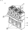
- the air circuit breaker 10 includes a cover unit 200, a driving unit 190, a circuit breaking unit 300, and an arc extinguishing unit 100.
- the air circuit breaker 10 includes a cover unit 200.
- the cover unit 200 forms the outer shape of the air circuit breaker 10.
- a space is formed inside the cover unit 200, and each component for operating the air circuit breaker 10 can be mounted in the space.
- the cover unit 200 functions as a kind of housing.
- the cover unit 200 may be formed of a material with high heat resistance and high rigidity. This is to prevent damage to each component mounted inside and to prevent damage caused by an arc generated inside.
- the cover unit 200 may be formed of synthetic resin or reinforced plastic.
- the cover unit 200 has a quadrangular pillar shape with a height in the up and down direction.
- the shape of the cover unit 200 may be provided in any shape capable of mounting components for operating the air circuit breaker 10 therein.
- the inner space of the cover unit 200 is energized to the outside.
- Each component mounted inside the cover unit 200 may be energizably connected to an external power source or load.
- the cover unit 200 includes an upper cover 210 and a lower cover 220.
- the upper cover 210 forms the upper side of the cover unit 200.
- the upper cover 210 is positioned above the lower cover 220.
- the upper cover 210 and the lower cover 220 may be integrally formed.
- a space is formed inside the upper cover 210.
- Various components provided in the air circuit breaker 10 are mounted in the space.
- the circuit breaking unit 300, the arc extinguishing unit 100, and the like may be mounted in the inner space of the upper cover 210.
- the inner space of the upper cover 210 communicates with the inner space of the lower cover 220.
- Components such as the circuit breaking unit 300 may be accommodated throughout the inner space of the upper cover 210 and the inner space of the lower cover 220.
- the arc extinguishing unit 100 is located on one side of the upper cover 210, i.e., on the upper surface in the illustrated embodiment.
- the arc extinguishing unit 100 may be partially exposed on the upper surface of the upper cover 210.
- the arc generated in the inner space of the upper cover 210 may pass through the arc extinguishing unit 100 and may be extinguished and discharged to the outside of the air circuit breaker 10.
- a fixed contact terminal 310 of the circuit breaking unit 300 is exposed on the other side of the upper cover 210, i.e., the front side in the illustrated embodiment.
- the fixed contact terminal 310 may be energizably connected to an external power source or load through the exposed portion.
- the upper cover 210 includes a first upper cover and a second upper cover.
- the first upper cover is configured to cover one side of the upper side of the air circuit breaker 10, i.e., the front side in the illustrated embodiment.
- the first upper cover is coupled to the second upper cover by any fastening means.
- An opening is formed in the first upper cover.
- the fixed contact terminal 310 may be exposed to the outside through the opening.
- three of said openings are formed in the left-right direction.
- the second upper cover is configured to cover the other side of the upper side of the air circuit breaker 10, i.e., the rear side in the illustrated embodiment.
- the second upper cover is coupled to the first upper cover by any fastening means.
- the lower cover 220 forms the lower side of the cover unit 200.
- the lower cover 220 is positioned below the upper cover 210.
- a space is formed inside the lower cover 220.
- Various components provided in the air circuit breaker 10 are mounted in the space.
- the driving unit 190, the circuit breaking unit 300, and the like may be mounted in the inner space of the lower cover 220.
- the inner space of the lower cover 220 communicates with the inner space of the upper cover 210.
- Components such as the circuit breaking unit 300 may be accommodated throughout the inner space of the lower cover 220 and the inner space of the upper cover 210.
- a movable contact terminal 320 of the circuit breaking unit 300 is located on one side of the lower cover 220, i.e., the front side in the illustrated embodiment.
- the movable contact terminal 320 may be exposed to the outside through an opening formed in the lower cover 220.
- the movable contact terminal 320 may be energizably connected to an external power source or load through the exposed portion.
- the air circuit breaker 10 includes a driving unit 190.
- the driving unit 190 is rotated as the fixed contact 311 and the movable contact 321 of the circuit breaking unit 300 are spaced apart, thereby performing a trip mechanism. Accordingly, the air circuit breaker 10 may break energization with the outside, and the user can recognize that an operation to break energization has been performed.
- the driving unit 190 is accommodated inside the air circuit breaker 10. Specifically, the driving unit 190 is partially accommodated in a space inside the cover unit 200. In addition, the remaining portion of the driving unit 190 is accommodated inside a case provided on one side (the rear side in the illustrated embodiment) of the cover unit 200, which is not given with reference numerals.
- the driving unit 190 is connected to the circuit breaking unit 300. Specifically, a crossbar 192 of the driving unit 190 is configured to rotate together with the rotation of the movable contact terminal 320 of the circuit breaking unit 300.
- the driving unit 190 may be rotated together.
- the driving unit 190 is rotatably accommodated inside the air circuit breaker 10.
- the driving unit 190 includes a shooter 191, a crossbar 192 and a lever 193.
- the shooter 191 is rotated together as the movable contact terminal 320 of the circuit breaking unit 300 is rotated away from the fixed contact terminal 310.
- the shooter 191 is connected to the crossbar 192 and the lever 193.
- one end of the shooter 191 is restrained by the crossbar 192.
- An elastic member is provided at the other end of the shooter 191. Accordingly, in a state in which the fixed contact 311 and the movable contact 321 are in contact, the shooter 191 presses the elastic member and stores restoring force.
- the external force for the pressing may be provided by a state in which the crossbar 192 is rotated toward the fixed contact terminal 310.
- the movable contact 321 When the movable contact 321 is spaced apart from the fixed contact 311, the movable contact terminal 320 is rotated in a direction away from the fixed contact terminal 310. Accordingly, the crossbar 192 is also rotated, and one end of the shooter 191 is released and rotated by the restoring force provided by the elastic member.
- the shooter 191 is connected to the lever 193. As the shooter 191 is rotated and strikes the lever 193, the lever 193 may also be rotated, and a trip mechanism may be performed.
- the crossbar 192 is connected to the movable contact terminal 320 and is rotated together as the movable contact terminal 320 is rotated. Accordingly, the shooter 191 restrained by the crossbar 192 may be released, and a trip mechanism may be performed.
- the crossbar 192 may extend between the plurality of circuit breaking units 300. In the illustrated embodiment, a total of three movable contact terminals 320 of the circuit breaking unit 300 are provided and disposed in the left-right direction. The crossbar 192 may be connected through the plurality of movable contact terminals 320 disposed in the left-right direction.
- the crossbar 192 contacts the one end of the shooter 191 to restrain the shooter 191.
- the crossbar 192 is rotated together with the movable contact terminal 320, the crossbar 192 releases the one end of the shooter 191.
- the lever 193 may be hit and rotated by the rotating shooter 191.
- the lever 193 may be partially exposed to the outside of the air circuit breaker 10.
- the trip mechanism is performed by the circuit breaking unit 300, the lever 193 is rotated in a preset direction.
- the user can easily recognize that the trip mechanism has been performed.
- the user can rotate the lever 193 to adjust the air circuit breaker 10 to a state in which it can be energized again.
- the process of performing the trip mechanism by the driving unit 190 is a well-known technique, and thus a detailed description thereof will be omitted.
- the air circuit breaker 10 includes a circuit breaking unit 300.
- the circuit breaking unit 300 includes a fixed contact terminal 310 and a movable contact terminal 320 spaced apart from each other or in contact with each other.
- the air circuit breaker 10 may be energized with an external power source or load.
- the air circuit breaker 10 is de-energized from an external power source or load.
- the circuit breaking unit 300 is accommodated inside the air circuit breaker 10. Specifically, the circuit breaking unit 300 is rotatably accommodated in the inner space of the cover unit 200.
- the circuit breaking unit 300 may be energized with the outside.
- current from an external power source or load may flow into any one of the fixed contact terminal 310 and the movable contact terminal 320.
- current may flow from the other one of the fixed contact terminal 310 and the movable contact terminal 320 to an external power source or load.
- the circuit breaking unit 300 may be partially exposed to the outside of the air circuit breaker 10. Accordingly, the circuit breaking unit 300 may be energizably connected to an external power source or load through a member such as a conducting wire (not shown).
- a plurality of circuit breaking units 300 may be provided.
- the plurality of circuit breaking units 300 may be disposed to be spaced apart from each other in one direction.
- a partition wall (not shown) may be provided between each of the circuit breaking units 300 to prevent interference between currents energized to each of the circuit breaking units 300.
- three circuit breaking units 300 are provided.
- the three circuit breaking units 300 are disposed to be spaced apart from each other in the left-right direction of the air circuit breaker 10. This is because the air circuit breaker 10 according to an embodiment of the present invention is energized with three-phase currents such as R phase, S phase and T phase or U phase, V phase and W phase.
- the number of circuit breaking units 300 may be changed according to the number of phases of current flowing through the air circuit breaker 10.
- the fixed contact terminal 310 is exposed to the outside through an opening formed on the front side of the upper cover 210.
- the fixed contact terminal 310 may be formed of a material having electrical conductivity.
- the fixed contact terminal 310 may be formed of copper (Cu) or iron (Fe) and an alloy material including the same.
- the fixed contact terminal 310 includes a fixed contact 311.
- the fixed contact 311 may be in contact with or spaced apart from the movable contact 321.
- the fixed contact 311 is located on one side of the fixed contact terminal 310 towards the movable contact terminal 320, i.e., on the rear side in the illustrated embodiment.
- the fixed contact 311 is energized with the fixed contact terminal 310.
- the fixed contact 311 is located on the rear side of the fixed contact terminal 310.
- the fixed contact 311 may be integrally formed with the fixed contact terminal 310.
- the air circuit breaker 10 When the fixed contact 311 and the movable contact 321 are in contact with each other, the air circuit breaker 10 is energizably connected to an external power source or load. In addition, when the fixed contact 311 is spaced apart from the movable contact 321, the air circuit breaker 10 is de-energized from an external power source or load.
- the movable contact terminal 320 may be in contact with or spaced apart from the fixed contact terminal 310. It is as described above that the air circuit breaker 10 can be energized or de-energized from an external power source or load by contact and separation between the movable contact terminal 320 and the fixed contact terminal 310.
- the movable contact terminal 320 is rotatably installed in the inner space of the cover unit 200.
- the movable contact terminal 320 may be rotated in a direction toward the fixed contact terminal 310 and in a direction away from the fixed contact terminal 310.
- the movable contact terminal 320 is accommodated in the inner spaces of the upper cover 210 and the lower cover 220. It is as described above that the inner spaces of the upper cover 210 and the lower cover 220 may communicate with each other.
- the movable contact terminal 320 may be partially exposed to the outside of the air circuit breaker 10. Through the exposed portion, the movable contact terminal 320 may be energizably connected to an external power source or load.
- the movable contact terminal 320 is exposed to the outside through an opening formed on the front side of the lower cover 220.
- the movable contact terminal 320 may be formed of a material having electrical conductivity.
- the movable contact terminal 320 may be formed of copper or iron and an alloy material including the same.
- the movable contact terminal 320 is connected to the driving unit 190. Specifically, the movable contact terminal 320 is connected to the crossbar 192 of the driving unit 190. In an embodiment, the crossbar 192 may be coupled through the movable contact terminal 320.
- the crossbar 192 may also be rotated. Accordingly, the driving unit 190 may be operated to perform the trip mechanism.
- the movable contact terminal 320 includes a movable contact 321 and a rotation shaft 322.
- the movable contact 321 may be in contact with or spaced apart from the fixed contact 311.
- the movable contact 321 is located on one side of the movable contact terminal 320 towards the fixed contact terminal 310, i.e., on the front side in the illustrated embodiment.
- the movable contact 321 may be rotated together with the movable contact terminal 320. When the movable contact terminal 320 is rotated toward the fixed contact terminal 310, the movable contact 321 may also be rotated toward the fixed contact 311 to contact the fixed contact 311.
- the movable contact terminal 320 when the movable contact terminal 320 is rotated in a direction away from the fixed contact terminal 310, the movable contact 321 may also be spaced apart from the fixed contact 311.
- the movable contact 321 is energized with the movable contact terminal 320.
- the movable contact 321 is located on the front side of the movable contact terminal 320.
- the movable contact 321 may be integrally formed with the movable contact terminal 320.
- the air circuit breaker 10 is energized with or de-energized from an external power source or load by contact and separation between the movable contact 321 and the fixed contact 311.
- the air circuit breaker 10 includes various components for effectively extinguishing the generated arc within the arc extinguishing unit. This will be described later in detail.
- the rotation shaft 322 is a portion where the movable contact terminal 320 is rotatably coupled to the cover unit 200.
- the movable contact terminal 320 may be rotated in a direction toward the fixed contact terminal 310 or in a direction away from the fixed contact terminal 310 about the rotation shaft 322.
- the rotation shaft 322 is located on the other side of the movable contact terminal 320 opposite to the fixed contact terminal 310, i.e., on the rear side in the illustrated embodiment.
- the air circuit breaker 10 includes an arc extinguishing unit 100.
- the arc extinguishing unit 100 is configured to extinguish an arc generated when the fixed contact 311 and the movable contact 321 are spaced apart.
- the generated arc may pass through the arc extinguishing unit 100 and be discharged to the outside of the air circuit breaker 10 after being extinguished and cooled.
- the arc extinguishing unit 100 is coupled to the cover unit 200.
- One side of the arc extinguishing unit 100 for arc discharge may be exposed to the outside of the cover unit 200.
- the upper side of the arc extinguishing unit 100 is exposed to the outside of the cover unit 200.
- the arc extinguishing unit 100 is partially accommodated in the cover unit 200.
- the remaining portion of the arc extinguishing unit 100 except for the portion exposed to the outside may be accommodated in the inner space of the cover unit 200.
- the arc extinguishing unit 100 is partially accommodated on the upper side of the upper cover 210.
- the arrangement may be changed according to the position of the fixed contact 311 and the movable contact 312. That is, the arc extinguishing unit 100 may be positioned fairly adjacent to the fixed contact 311 and the movable contact 312. Accordingly, an arc formed by extending along the movable contact 312 rotated away from the fixed contact 311 may easily enter the arc extinguishing unit 100.
- a plurality of arc extinguishing units 100 may be provided.
- the plurality of arc extinguishing units 100 may be disposed to be physically and electrically spaced apart from each other.
- three arc extinguishing units 100 are provided. As described above, this is due to the passage of three-phase current through the air circuit breaker 10 according to an embodiment of the present invention.
- each arc extinguishing unit 100 is positioned adjacent to each fixed contact 311 and movable contact 321. In the illustrated embodiment, each arc extinguishing unit 100 is positioned adjacent to the upper side of each fixed contact 311 and movable contact 321.
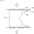
- each arc extinguishing unit 100 is configured to extinguish an arc generated when the current of each phase energized to each circuit breaking unit 300 is broken. Air flows in from the lower end of the arc extinguishing unit 100, extinguishes the arc, and is discharged upward from the arc extinguishing unit 100.
- the arc extinguishing units 100 may be disposed adjacent to each other. In the illustrated embodiment, the three arc extinguishing units 100 are disposed side by side in the left-right direction of the air circuit breaker 10.
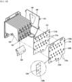
- the arc extinguishing unit 100 includes a side plate part 105, a grid 130, and a cover assembly 120.
- Side plate part 105 forms both sides of arc extinguishing unit 100, i.e., the right side and the left side in the illustrated embodiment.
- the side plate part 105 is coupled to each component of the arc extinguishing unit 100 and supports the components.
- the side plate part 105 is coupled to the grid 130, the cover assembly 120, an arc guide 150 and an arc runner 140.
- a plurality of side plate parts 105 are provided.
- the plurality of side plate parts 105 may be spaced apart from each other and disposed to face each other.
- two side plate parts 105 are provided, forming the right and left sides of the arc extinguishing unit 100, respectively.
- the side plate part 105 may be formed of an insulating material. This is to prevent the generated arc from flowing toward the side plate part 105.
- the side plate part 105 may be formed of a heat-resistant material. This is to prevent damage or shape deformation by the generated arc.
- the side plate part 105 includes a gassing material 111 that generates molecules that extinguish the arc when heat generated by the arc is applied.
- the gassing material 111 when heat generated by an arc is applied to the gassing material 111, the gassing material 111 emits molecules capable of extinguishing the arc. In other words, the gassing material 111 can generate gases that can extinguish the arc. Through this, the arc generated in the arc extinguishing unit 100 can be quickly extinguished.
- An outer support plate 110 is disposed outside the gassing material 111.
- the outer support plate 110 is coupled to the grid 130.
- the outer support plate 110 may press and fix the gassing material 111 toward the grid 130.
- the aforementioned gassing material 111 emits molecules for arc extinguishing when heated by an arc, physical strength may be weakened.
- the heat generated by the arc can momentarily reach several thousand degrees Celsius. Accordingly, the physical strength of the gassing material 111 may be weakened.
- the outer support plate 110 disposed outside the gassing material 111 may serve to support the gassing material 111.
- the outer support plate 110 may include a fiber-reinforced polyester composite.
- the outer support plate 110 may be made of a mat containing glass, that is, a glass fiber reinforced material so that physical strength is not weakened by the heat of the arc. Through this, the outer support plate 110 can be reinforced in mechanical and thermal strength.
- the outer support plate 110 may be made of a substantially fiber-reinforced polyester composite selected from materials sold under the trademark Altherm 800 or Delmat polyester by the company VON ROLL.
- the outer support plate 110 may be made of a glass fiber reinforced material selected from materials sold under the trademark Delmat Epoxy 68660.
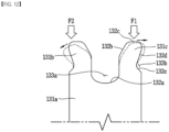
- the grid 130 may include a protrusion part 131 protruding from a side surface to be coupled to the side plate part 105.
- the protrusion part 131 may include a body part 131a extending from the side of the grid 130, and a first protrusion 131b and a second protrusion 131c extending from the body part 131a to both sides.
- first protrusion 131b and the second protrusion 131c are spaced apart from each other and extend outwardly from the body part 131a.
- the first protrusion 131b and the second protrusion 131c may extend in directions away from each other in a symmetrical manner about the center of the body part 131a.
- a U-groove 133a may be formed in a space between the first protrusion 131b and the second protrusion 131c.
- a U-groove 133a capable of absorbing left and right deformation of the first protrusion 131b and the second protrusion 131c due to an external force may be formed.
- a concave groove 133b capable of absorbing back and forth deformation of the first protrusion 131b and the second protrusion 131c by an external force may be formed.
- the first protrusion 131b and the second protrusion 131c may be formed of a first surface 132a to a fifth surface 132e from the space forming the U-groove 133a to the place forming the concave groove 133b.
- they may include a first surface 132a constituting the U-groove 133a; a second surface 132b extending from the first surface 132a to extend at a predetermined angle in a direction in which the first protrusion 131b and the second protrusion 131c go away from each other; a third surface 132c extending from the second surface 132b and forming a surface including a flat surface toward the outside; a fourth surface 132d forming a predetermined angle with the third surface 132c and parallel or at a small angle with the second surface 132b; and a fifth surface 132e extending at a predetermined angle with the fourth surface 132d and forming a concave groove 133b with the fourth surface 132d.
- the fifth surface 132e may be connected to the body part 131a.
- the protrusion part 131 when the protrusion part 131 receives pressure from the outside, the first protrusion 131b and the second protrusion 131c may show two types of behavior.
- the protrusion part 131 may behave as follows.
- the first protrusion 131b may be bent toward the concave groove 133b.
- the concave groove 133b may serve as an avoidance space in which the first protrusion 131b can bend toward the concave groove 133b.
- the concave groove 133b is also formed in the second protrusion 131c, the same behavior can be performed when an external force is applied to the outside of the third surface 132c of the second protrusion 131c.
- the second protrusion 131c may be moved in a direction away from the first protrusion 131b. Even in this case, since the concave groove 133b is formed, the second protrusion 131c can be easily moved in a direction away from the first protrusion 131b.
- the gassing material 111 which may deteriorate physical rigidity due to the heat of the arc, is disposed inside the side plate part 105, the coupling between the grid 130 and the side plate part 105 may be weakened. Therefore, as the protrusion part 131 of the grid 130 is formed of the body part 131a, the first protrusion 131b, and the second protrusion 131c, the arc extinguishing unit 100 according to an embodiment of the present invention y may be firmly coupled to the gassing material 111 and the outer support plate 110.
- the U-groove 133a and the concave groove 133b are formed in the protrusion part 131 to provide space for the first protrusion 131b and second protrusion 131c to avoid external force, thereby reducing the damage or permanent deformation of the first protrusion 131b and the second protrusion 131c due to an external force.
- a plurality of through holes are formed in the side plate part 105.
- the grid 130 and the arc runner 140 may be inserted and coupled to some of the through holes.
- fastening members for fastening the cover assembly 120 and the arc guide 150 to the side plate part 105 may be coupled through some of the other through holes.
- the side plate part 105 is coupled to the grid 130. Specifically, protrusion parts 131 provided at opposite sides of the grid 130, i.e., the right end and the left end in the illustrated embodiment, are inserted into and coupled to some of the through holes of the side plate part 105.
- a first through hole 110a into which the protrusion part 131 of the grid 130 is inserted and a second through hole 110b into which the arc runner protrusion part 141 is inserted may be formed in the outer support plate 110.
- a first through hole 111a into which the protrusion part 131 of the grid 130 is inserted and a second through hole 111b into which the arc runner protrusion part 141 is inserted may also be formed in the gassing material 111.
- Each through hole of the outer support plate 110 and the gassing material 111 is formed at a position corresponding to each other so that the protrusion parts 131 formed on the grid 130 and the arc runner 140 can be simultaneously inserted.
- the protrusion part 131 of the grid 130 may be vertically disposed along the longitudinal direction of the grid 130. Accordingly, the first through holes 110a and 111a of the gassing material 111 and the outer support plate 110 may be formed vertically.
- the protrusion part 131 of the grid 130 may be formed in a horizontal direction perpendicular to the longitudinal direction of the grid 130. Specifically, referring to FIG. 14 , the protrusion part 131 of the grid 130 is formed in a direction perpendicular to the longitudinal direction of the grid 130. In this case, the first through holes of the outer support plate 110 and the gassing material 111 may be formed in the horizontal direction as shown. Meanwhile, in another embodiment, the arc runner protrusion part 141 may also be formed in a direction perpendicular to the longitudinal direction.
- the outer support plate 110 may include a central member 110c formed in the through hole and extending across the through hole so that the first protrusion 131b and the second protrusion 131c can be inserted separately from each other.
- a central member 110c extending across the through hole may be formed in the first through hole 110a of the outer support plate 110.
- the body part 131a of the protrusion part 131 passes through the gassing material 111.
- the first protrusion 131b and the second protrusion 131c of the protrusion part 131 pass through the first through hole 110a of the outer support plate 110, respectively.
- the first protrusion 131b and the second protrusion 131c may be inserted into different regions of the first through hole 110a with the central member 110c as the center.
- the central member 110c may serve as a rib of the first through hole 110a.
- the central member 110c since the central member 110c is formed, the first through hole 110a can have increased rigidity against the behavior of the protrusion part 131.
- the side plate part 105 is provided in a plate shape having a plurality of edges formed at vertices.
- the side plate part 105 may be provided in any shape capable of forming both sides of the arc extinguishing unit 100 and supporting each component of the arc extinguishing unit 100.
- the side plate part 105 is coupled to the cover assembly 120.
- the cover assembly 120 is coupled to the upper side of the side plate part 105.
- the above coupling may be achieved by a fitting coupling between the side plate part 105 and the cover assembly 120 or by a separate fastening member.
- the side plate part 105 is coupled to the arc guide 150.
- the arc guide 150 is coupled to the lower side of the side plate part 105, that is, to one side opposite to the cover assembly 120.
- the above coupling may be achieved by a separate fastening member.
- the side plate part 105 is coupled to the arc runner 140.
- the arc runner 140 is coupled to the rear side of the side plate part 105, that is, to one side opposite to the fixed contact 311.
- the above coupling may be achieved by a separate fastening member.
- the grid 130 guides an arc generated when the fixed contact 311 and the movable contact 321 are spaced apart to the arc extinguishing unit 100.
- the grid 130 may be formed of a magnetic body. This is to apply an attractive force to the arc, which is a flow of electrons.
- a plurality of grids 130 may be provided.
- the plurality of grids 130 may be spaced apart from each other and stacked.
- eleven grids 130 are provided and stacked in the front-rear direction.
- the number of grids 130 may be changed. Specifically, the number of grids 130 may be changed according to the size and performance of the arc extinguishing unit 100, or the rated capacity of the air circuit breaker 10 in which the arc extinguishing unit 100 is provided, or the like.
- An introduced arc may be subdivided and flowed through a space formed by the plurality of grids 130 being spaced apart from each other. Accordingly, the pressure of the arc may be increased, and the moving speed and the extinguishing speed of the arc may be increased.
- the arc runner 140 is positioned adjacent to the grid 130 furthest from the fixed contact 311 among the plurality of grids 130, i.e., the grid 130 on the rear side in the illustrated embodiment.
- An end of the grid 130 in the width direction i.e., left-right direction in the illustrated embodiment, may be formed to protrude toward the fixed contact 311, that is, toward the lower side. That is, the grid 130 is formed in a peak shape with left and right ends pointing downward.
- the generated arc may effectively proceed toward the end of the grid 130 in the left-right direction, and may easily flow to the arc extinguishing unit 100.
- the arc guide 150 is located on the outer side of the left-right end of the grid 130, i.e., on the lower side in the illustrated embodiment.
- the grid 130 is coupled to the side plate part 105.
- a plurality of protrusion parts 131 are formed at the edges of the grid 130 in the width direction, i.e., the left-right direction in the illustrated embodiment, in the extension direction, i.e., the up-down direction in the illustrated embodiment.
- the protrusion part 131 of the grid 130 is inserted into and coupled to the through hole formed in the side plate part 105.
- One side of the grid 130 facing the cover assembly 120 i.e., the upper end in the illustrated embodiment, may be positioned adjacent to the cover assembly 120.
- the arc flowing along the grid 130 may pass through the cover assembly 120 and be discharged to the outside.
- the cover assembly 120 forms the upper side of the arc extinguishing unit 100.
- the cover assembly 120 is configured to cover the upper end of the grid 130.
- the arc passing through the space formed by the plurality of grids 130 spaced apart from each other may be discharged to the outside of the air circuit breaker 10 through the cover assembly 120.
- the cover assembly 120 is coupled to the side plate part 105.
- a protrusion inserted into the through hole of the side plate part 105 may be formed at an edge of the cover assembly 120 in the width direction, i.e., the left-right direction in the illustrated embodiment.
- the cover assembly 120 and the side plate part 105 may be coupled by a separate fastening member.
- the cover assembly 120 is formed to extend in one direction, i.e., in the front-rear direction in the illustrated embodiment. It will be understood that the above direction is the same as the direction in which the plurality of grids 130 are stacked.
- the length of the cover assembly 120 in the other direction i.e., the width direction in the illustrated embodiment, may be determined according to the length of the plurality of grids 130 in the width direction.
- the cover assembly 120 includes an upper frame 121, a mesh part 123, a first insulation filter 124, a second insulation filter 126, a spacer 125, a cover body 122, and a packing part 122b.
- the cover body 122 forms the outer shape of the cover assembly 120.
- the cover body 122 is coupled to the side plate part 105.
- the upper frame 121 is coupled to the cover body 122.
- a predetermined space is formed inside the cover body 122.
- the space may be covered by the upper frame 121.
- the mesh part 123, the first insulation filter 124, the second insulation filter 126, and the spacer 125 are accommodated in the space. Accordingly, the space may be referred to as an "accommodation space".
- the accommodation space communicates with a space formed by spacing the grids 130 apart.
- the accommodation space communicates with the inner space of the cover unit 200. Accordingly, the generated arc can flow into the accommodation space of the cover body 122 by passing through the space formed by the separation of the grids 130.
- An upper end of the grid 130 may be in contact with one side of the cover body 122 facing the grid 130, i.e., the lower side in the illustrated embodiment.
- the cover body 122 may support the upper end of the grid 130.
- the cover body 122 may be formed of a heat-resistant material. This is to prevent damage or shape deformation by the generated arc.
- the length of the cover body 122 in the front-rear direction is longer than the length in the left-right direction.
- the shape of the cover body 122 may be changed according to the shape of the side plate part 105 and the shape and number of the grids 130.
- the upper frame 121 is coupled to one side of the cover body 122 opposite to the grid 130, i.e., the upper side in the illustrated embodiment.
- the upper frame 121 is coupled to the upper side of the cover body 122.
- the upper frame 121 is configured to cover the accommodation space formed in the cover body 122, and the mesh part 123, the first insulation filter 124, the second insulation filter 126, and the spacer 125 accommodated in the accommodation space.
- the length of the upper frame 121 in the front-rear direction is longer than the length in the left-right direction.
- the upper frame 121 may be provided in an arbitrary shape capable of stably being coupled to the upper side of the cover body 122 and covering the accommodation space and components accommodated in the accommodation space.
- a plurality of through holes 121a are formed in the upper frame 121. Through the through hole, an arc passing between the grids 130 and extinguished may be discharged.
- the through-holes 121a are provided in four lines in the front-rear direction, three each in the left-right direction, and a total of 12 are formed. The number of through holes may be changed.
- the through holes are located to be spaced apart from each other.
- a kind of rib is formed between the through holes.
- the rib may press the mesh part 123, the first insulation filter 124, the second insulation filter 126, and the spacer 125 accommodated in the space of the cover body 122 from the upper side.
- the mesh part 123, the first insulation filter 124, the second insulation filter 126, and the spacer 125 are not arbitrarily separated from the accommodation space of the cover body 122.
- the upper frame 121 may be fixedly coupled to an upper side of the cover body 122.
- the upper frame 121 is fixedly coupled to the upper side of the cover body 122 by a fastening member.
- the mesh part 123, the first insulation filter 124, second insulation filter 126, and the spacer 125 are positioned in the accommodation space of the cover body 122 between the upper frame 121 and the cover body 122, that is, in the lower side of the upper frame 121.
- the mesh part 123, the first insulation filter 124, the spacer 125, and the second insulation filter 126 are stacked from top to bottom in the accommodation space of the cover body 122.
- the mesh part 123 passes through a space formed between the grids 130 and serves to filter out impurities remaining in the extinguished arc.
- the extinguished arc may pass through the mesh part 123 and be discharged to the outside after remaining impurities are removed.
- the mesh part 123 functions as a kind of filter.
- the mesh part 123 may include a plurality of layers. In this case, each layer may be made of wires having different diameters.
- the mesh part 123 includes a plurality of through holes. It is preferable that the size, that is, the diameter of the through hole is smaller than the diameter of the impurity particles remaining in the arc. In addition, it is preferable that the diameter of the through hole is sufficiently large so that the gas included in the arc can pass through.
- a plurality of mesh parts 123 may be provided.
- the plurality of mesh parts 123 may be stacked in the up and down direction. Accordingly, impurities remaining in the arc passing through the mesh part 123 can be effectively removed.
- the mesh part 123 is accommodated in the accommodation space formed inside the cover body 122.
- the shape of the mesh part 123 may be determined according to the shape of the accommodation space.
- the mesh part 123 is located below the upper frame 121.
- the plurality of through holes formed in the mesh part 123 communicate with the plurality of through holes formed in the upper frame 121. Accordingly, the arc passing through the mesh part 123 may pass through the upper frame 121 and be discharged to the outside.
- the plurality of through holes formed in the mesh part 123 communicate with a space in which the grids 130 are spaced apart. As a result, the plurality of through holes formed in the mesh part 123 communicate with the inner space of the cover unit 200.
- the first insulation filter 124, the second insulation filter 126, and the spacer 125 are positioned below the mesh part 123.
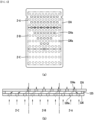
- the first insulation filter 124 may be disposed below the mesh part 123, and an exhaust hole 124a may be formed in a partial area thereof.
- a plurality of exhaust holes 124a aligned in the width direction and the longitudinal direction, are formed in the first insulation filter 124.
- the first insulation filter 124 may be divided into three regions along the longitudinal direction.
- the first insulation filter 124 may be divided into a first region Z-A, a second region Z-B, and a third region Z-C along the longitudinal direction.
- the exhaust hole 124a may be formed in the entire area in the width direction of the first region Z-A. In addition, the exhaust hole 124a may be formed in a partial area in the width direction of the second region Z-B. The exhaust hole 124a is not formed in the third region Z-C.
- the plurality of exhaust holes 124a formed in the second region Z-B are formed at the center in the width direction in an area adjacent to the third region Z-C. And the plurality of exhaust holes 124a formed in the second region Z-B are formed throughout the width direction in an area adjacent to the first region Z-A. And the number of exhaust holes 124a formed from the third region Z-C to the first region Z-A may increase.
- the plurality of exhaust holes 124a formed in the second region Z-B are formed wide in the width direction near the first region Z-A, and are formed only in the central portion near the third region Z-C. That is, the exhaust hole 124a formed in the second region Z-B may have an inverted triangle shape in which a portion close to the first region Z-A forms a long side.
- the second insulation filter 126 may be disposed below the first insulation filter 124, and an exhaust hole 126a may be formed in an area different from the exhaust hole 124a of the first insulation filter 124.
- the spacer 125 may be interposed between the first insulation filter 124 and the second insulation filter 126.
- the spacer 125 may maintain a distance between the first insulation filter 124 and the second insulation filter 126.
- the first insulation filter 124 and the second insulation filter 126 are arranged up and down around the spacer 125.
- the exhaust holes 124a are formed differently in the first region Z-A and the second region Z-B, and the exhaust hole 124a is not formed in the third region Z-C.
- exhaust hole 126a formed in the second insulation filter 126 and the exhaust hole 124a formed in the first insulation filter 124 may be formed at different positions.
- the arc generated inside the arc extinguishing unit 100 may be discharged toward the upper frame 121 through the second insulation filter 126, the spacer 125, and the first insulation filter 124.
- the positions of the exhaust holes formed in the first insulation filter 124 and the second insulation filter 126 are different, and the exhaust holes 124a are formed differently according to regions in the first insulation filter 124.
- the arc generated in the region corresponding to the first region Z-A of the first insulation filter 124 inside the arc extinguishing unit 100 can be discharged relatively easily along the exhaust hole 126a formed in the second insulation filter 126 and the exhaust hole 124a formed in the first insulation filter 124.
- arcs generated in an area corresponding to the second region Z-B of the first insulation filter 124 inside the arc extinguishing unit 100 may have reduced discharge compared to arcs generated in an area corresponding to the first region Z-A.
- arcs generated in an area corresponding to the third region Z-C of the first insulation filter 124 inside the arc extinguishing unit 100 may have further reduced discharge compared to arcs generated in areas corresponding to the first region Z-A and the second region Z-B.
- the second insulation filter 126 may function to adjust the initial pressure inside the arc extinguishing unit 100 by forming exhaust holes 126a at regular intervals on the front surface of the filter.
- the first insulation filter 124 may function to adjust the pressure inside the arc extinguishing unit 100 by configuring the arrangement and formation location of the exhaust hole 124a differently according to the region. Specifically, it may lower the pressure in the area corresponding to the first region Z-A and increase the pressure in the corresponding area toward the second region Z-B and the third region Z-C.
- the arc generated inside the arc extinguishing unit 100 can be easily applied to the grid 130. That is, since the pressure increases toward the rear surface of the arc extinguishing unit 100, the generated arc may receive a force to rise upward. As a result, the probability that the arc is applied to the adjacent grid 130 increases.
- the cover body 122 may fix the positions of the mesh part 123, the first insulation filter 124, the spacer 125, and the second insulation filter 126 by accommodating them in an internal space.
- the cover body 122 may include a base 122a and a packing part 122b coupled to the base 122a.
- the packing part 122b is coupled to the cover body 122.
- the packing part 122b blocks a space between the outside and the cover assembly 120. Accordingly, the packing part 122b is made to maintain the pressure inside the arc extinguishing unit 100.
- a coupling protrusion 122c may protrude from a sidewall of the inner space of the cover body 122. Specifically, in the illustrated embodiment, a coupling protrusion 122c protrudes from the upper sidewall of the inner space of the cover body 122.
- concave fitting grooves 124b, 125b, and 126b may be formed on sidewalls of the first insulation filter 124, the spacer 125, and the second insulation filter 126 so that the above-described coupling protrusion 122c can be inserted.
- the arc guide 150 guides a generated arc so that the arc flows toward the grid 130. It is possible to prevent damage to the side plate part 105 by flowing the generated arc toward the side plate part 105 by the arc guide 150.
- the arc guide 150 is located on one side of the side plate part 105 facing the fixed contact 311 and the movable contact 321. In the illustrated embodiment, the arc guide 150 is located on the lower side of the side plate part 105.
- a plurality of arc guides 150 may be provided.
- the plurality of arc guides 150 may be coupled to each side plate part 105.
- two arc guides 150 are provided and coupled to each side plate part 105, respectively.
- the two arc guides 150 are arranged to face each other.
- the arc guide 150 is coupled to the side plate part 105.
- the above coupling may be achieved by a separate fastening member.
- the arc guide 150 may be formed of a heat-resistant material. This is to prevent damage and shape deformation due to the generated arc.
- the arc guide 150 may be formed of a ceramic material.
- the arc guide 150 is disposed to partially encase a peak portion formed on opposite sides of the grid 130, i.e., on the end in the left-right direction in the illustrated embodiment. Accordingly, arcs guided by the arc guide 150 may not be concentrated on any one part of the grid 130.
- the arc guide 150 may extend in the extension direction of the side plate part 105, i.e., in the front-rear direction in the illustrated embodiment. That is, the arc guide 150 may extend between the grid 130 located at the frontmost side and the grid 130 located at the rearmost side.
- the arc guide 150 includes a vertical portion 151 and a protruding portion 152.
- the vertical portion 151 is a portion where the arc guide 150 is coupled to the side plate part 105.
- the vertical portion 151 is located on one side of the side plate part 105 facing the fixed contact terminal 310, i.e., on the lower side in the illustrated embodiment.
- the vertical portion 151 may be coupled to the side plate part 105 by a fastening member.
- the vertical portion 151 extends in a direction toward the grid 130, i.e., upward in the illustrated embodiment. In an embodiment, the vertical portion 151 may extend while being in contact with the side plate part 105. In another embodiment, the vertical portion 151 may extend parallel to the side plate part 105.
- the protruding portion 152 extends from an end portion of the vertical portion 151.
- the protruding portion 152 is formed to partially encase a peak portion formed at an end portion of the grid 130 in the left-right direction.
- One surface of the protruding portion 152 is formed to form a predetermined angle with the vertical portion 151.
- one surface of the protruding portion 152 may extend, forming an obtuse angle with the vertical portion 151.
- the protruding portion 152 may extend parallel to a peak portion formed at an end portion of the grid 130 in the left-right direction.
- a bent portion 152a may be formed at an end portion of the protruding portion 152.
- the bent portion 152a may be formed between one surface of the protruding portion 152 extending while forming a predetermined angle with the vertical portion 151 and another surface extending toward the vertical portion 151 again. This bent portion 152a forms a peak, so that an arc can be more easily guided.
- the arc runner 140 guides a generated arc so that the arc flows toward the grid 130.
- the arc guide 150 it is possible to prevent the generated arc from advancing to one wall of the cover unit 200 beyond the grid 130. Accordingly, it is possible to prevent the cover unit 200 from being damaged by the generated arc.
- the arc runner 140 is located on one side of the side plate part 105 facing the fixed contact 311 and the movable contact 321. In the illustrated embodiment, the arc runner 140 is located on the lower side of the side plate part 105.
- the arc runner 140 is located on the other side of the side plate part 105 opposite to the fixed contact 311. Specifically, the arc runner 140 is located on the rear side in the lower side of the side plate part 105 so as to be opposite to the fixed contact 311 located on the front side of the side plate part 105.
- the arc runner 140 is coupled to the side plate part 105.
- the coupling may be formed by inserting a protrusion formed at an end of the arc runner 140 in the left-right direction into a through hole formed in the side plate part 105.
- the arc runner 140 may be formed of a conductive material. This is to guide the arc effectively by applying an attractive force to the flowing arc.
- the arc runner 140 may be formed of copper, iron, or an alloy including the same.
- the arc runner 140 extends toward the grid 130 by a predetermined length.
- the arc runner 140 may be disposed to cover the grid 130 located farthest from the fixed contact 311, i.e., the grid 130 located at the rearmost side in the illustrated embodiment, from the rear side.
- the arc does not extend beyond the grid 130 located at the rearmost side, damage to the cover unit 200 can be prevented. Also, the generated arc can be effectively guided toward the grid 130.
- the arc runner 140 may have an arc runner protrusion part 141 on its side surface.
- the arc runner protrusion part 141 may be coupled to the side plate part 105 through the through holes 110b and 111b formed in the side plate part 105. Meanwhile, an arc runner opening 142 may be formed at a central portion of the arc runner 140.
- a low runner 145 is disposed on the fixed contact terminal 310.
- the low runner 145 is disposed obliquely toward the arc extinguishing unit 100 above the fixed contact 311.
- the low runner 145 may guide an arc so that the arc generated when the fixed contact 311 and the movable contact 321 are in contact with each other and spaced apart may be guided toward the grid 130.
- the low runner 145 may be formed of a conductive material. This is to guide the arc effectively by applying an attractive force to the flowing arc.
- the low runner 145 may be formed of copper, iron, or an alloy including the same.
- the low runner 145 extends toward the grid 130 by a predetermined length. In an embodiment, the low runner 145 may extend adjacent to the grid 130 located closest to the fixed contact 311.
- the arc does not extend beyond the grid 130 located at the frontmost side, damage to the cover unit 200 can be prevented. Also, the generated arc can be effectively guided toward the grid 130.
Landscapes
- Arc-Extinguishing Devices That Are Switches (AREA)
- Breakers (AREA)
Applications Claiming Priority (2)
| Application Number | Priority Date | Filing Date | Title |
|---|---|---|---|
| KR1020210054463A KR20220147380A (ko) | 2021-04-27 | 2021-04-27 | 아크 소호부 및 이를 포함하는 기중 차단기 |
| PCT/KR2022/005787 WO2022231219A1 (fr) | 2021-04-27 | 2022-04-22 | Unité d'extinction d'arc et disjoncteur à air la comprenant |
Publications (1)
| Publication Number | Publication Date |
|---|---|
| EP4333013A1 true EP4333013A1 (fr) | 2024-03-06 |
Family
ID=83848177
Family Applications (1)
| Application Number | Title | Priority Date | Filing Date |
|---|---|---|---|
| EP22796052.3A Pending EP4333013A1 (fr) | 2021-04-27 | 2022-04-22 | Unité d'extinction d'arc et disjoncteur à air la comprenant |
Country Status (4)
| Country | Link |
|---|---|
| EP (1) | EP4333013A1 (fr) |
| KR (1) | KR20220147380A (fr) |
| CN (1) | CN116830230A (fr) |
| WO (1) | WO2022231219A1 (fr) |
Families Citing this family (1)
| Publication number | Priority date | Publication date | Assignee | Title |
|---|---|---|---|---|
| CN117727595B (zh) * | 2024-02-07 | 2024-04-26 | 温州华嘉电器有限公司 | 一种断路器灭弧室 |
Family Cites Families (5)
| Publication number | Priority date | Publication date | Assignee | Title |
|---|---|---|---|---|
| KR0131343Y1 (ko) * | 1995-07-31 | 1998-12-15 | 이정식 | 퍼스널 컴퓨터의 전원제어회로 |
| KR19990001783U (ko) * | 1997-06-23 | 1999-01-15 | 구자홍 | 회로차단기의 아크쳄버어셈블리의 그리드결합구조 |
| KR200393296Y1 (ko) * | 2005-05-17 | 2005-08-22 | 엘에스산전 주식회사 | 배선용 차단기의 소호장치 |
| US7488915B2 (en) * | 2006-09-20 | 2009-02-10 | Eaton Corporation | ARC baffle, and ARC chute assembly and electrical switching apparatus employing the same |
| KR101986552B1 (ko) * | 2018-11-14 | 2019-06-07 | 엘에스산전 주식회사 | 직류용 기중차단기의 아크소호장치 |
-
2021
- 2021-04-27 KR KR1020210054463A patent/KR20220147380A/ko not_active Application Discontinuation
-
2022
- 2022-04-22 CN CN202280014190.5A patent/CN116830230A/zh active Pending
- 2022-04-22 WO PCT/KR2022/005787 patent/WO2022231219A1/fr active Application Filing
- 2022-04-22 EP EP22796052.3A patent/EP4333013A1/fr active Pending
Also Published As
| Publication number | Publication date |
|---|---|
| KR20220147380A (ko) | 2022-11-03 |
| WO2022231219A1 (fr) | 2022-11-03 |
| CN116830230A (zh) | 2023-09-29 |
Similar Documents
| Publication | Publication Date | Title |
|---|---|---|
| CN101562083B (zh) | 用于断路器的电弧隔板组件 | |
| EP2064718B1 (fr) | Isolateur d'isolation gazeuse, et ensemble boîte de soufflage et dispositif de commutation électrique l'utilisant | |
| KR200393296Y1 (ko) | 배선용 차단기의 소호장치 | |
| US20150270075A1 (en) | Modular gas exhaust assembly for a circuit breaker | |
| US20230128751A1 (en) | Air circuit breaker | |
| EP4333013A1 (fr) | Unité d'extinction d'arc et disjoncteur à air la comprenant | |
| JP2012174686A (ja) | 消弧部を有する配線用遮断器 | |
| US20230170167A1 (en) | Arc extinguishing unit and air circuit breaker comprising same | |
| US20060213873A1 (en) | ARC chute assembly and electric power switch incorporating same | |
| US9697968B2 (en) | Electrical circuit breaker | |
| US20230115892A1 (en) | Air circuit breaker | |
| EP4339981A1 (fr) | Unité d'extinction d'arc, unité d'interruption et disjoncteur à air correspondant | |
| EP4336533A1 (fr) | Unité de disjoncteur et disjoncteur à air la comprenant | |
| KR20220061718A (ko) | 아크 소호부 및 이를 포함하는 기중 차단기 | |
| EP4336534A1 (fr) | Unité d'extinction d'arc et disjoncteur à air la comprenant | |
| KR20220151448A (ko) | 차단부 및 이를 포함하는 기중 차단기 | |
| US20240047163A1 (en) | Interrupter and air circuit breaker comprising same | |
| EP4339982A1 (fr) | Unité de coupure de circuit et disjoncteur à air la comprenant | |
| EP4339983A1 (fr) | Unité d'extinction d'arc et disjoncteur à air la comprenant | |
| US20230110171A1 (en) | Arc extinguishing unit and air circuit breaker comprising same | |
| KR102666104B1 (ko) | 아크 소호부 및 이를 포함하는 기중 차단기 | |
| KR102594467B1 (ko) | 아크 소호부, 차단부 및 이를 포함하는 기중 차단기 | |
| JP2013149619A (ja) | アークシュートアセンブリ及びその製造方法 | |
| KR102666107B1 (ko) | 아크 소호부 및 이를 포함하는 기중 차단기 | |
| KR20220155094A (ko) | 아크 소호부, 차단부 및 이를 포함하는 기중 차단기 |
Legal Events
| Date | Code | Title | Description |
|---|---|---|---|
| STAA | Information on the status of an ep patent application or granted ep patent |
Free format text: STATUS: THE INTERNATIONAL PUBLICATION HAS BEEN MADE |
|
| PUAI | Public reference made under article 153(3) epc to a published international application that has entered the european phase |
Free format text: ORIGINAL CODE: 0009012 |
|
| STAA | Information on the status of an ep patent application or granted ep patent |
Free format text: STATUS: REQUEST FOR EXAMINATION WAS MADE |
|
| 17P | Request for examination filed |
Effective date: 20230905 |
|
| AK | Designated contracting states |
Kind code of ref document: A1 Designated state(s): AL AT BE BG CH CY CZ DE DK EE ES FI FR GB GR HR HU IE IS IT LI LT LU LV MC MK MT NL NO PL PT RO RS SE SI SK SM TR |