EP2110672B1 - Acceleration sensor - Google Patents
Acceleration sensor Download PDFInfo
- Publication number
- EP2110672B1 EP2110672B1 EP08720344A EP08720344A EP2110672B1 EP 2110672 B1 EP2110672 B1 EP 2110672B1 EP 08720344 A EP08720344 A EP 08720344A EP 08720344 A EP08720344 A EP 08720344A EP 2110672 B1 EP2110672 B1 EP 2110672B1
- Authority
- EP
- European Patent Office
- Prior art keywords
- electrode
- capacitance
- weight
- opposed
- axis
- Prior art date
- Legal status (The legal status is an assumption and is not a legal conclusion. Google has not performed a legal analysis and makes no representation as to the accuracy of the status listed.)
- Active
Links
- 230000001133 acceleration Effects 0.000 title claims description 124
- 230000007423 decrease Effects 0.000 claims description 42
- 239000000758 substrate Substances 0.000 description 40
- 238000010586 diagram Methods 0.000 description 6
- 238000006073 displacement reaction Methods 0.000 description 5
- 230000008878 coupling Effects 0.000 description 4
- 238000010168 coupling process Methods 0.000 description 4
- 238000005859 coupling reaction Methods 0.000 description 4
- 239000011521 glass Substances 0.000 description 4
- 239000000969 carrier Substances 0.000 description 3
- 239000000853 adhesive Substances 0.000 description 2
- 230000001070 adhesive effect Effects 0.000 description 2
- 239000006121 base glass Substances 0.000 description 2
- 230000000694 effects Effects 0.000 description 2
- XUIMIQQOPSSXEZ-UHFFFAOYSA-N Silicon Chemical compound [Si] XUIMIQQOPSSXEZ-UHFFFAOYSA-N 0.000 description 1
- 239000003990 capacitor Substances 0.000 description 1
- 239000000284 extract Substances 0.000 description 1
- 239000000463 material Substances 0.000 description 1
- 229910052710 silicon Inorganic materials 0.000 description 1
- 239000010703 silicon Substances 0.000 description 1
- 239000002210 silicon-based material Substances 0.000 description 1
- 230000001360 synchronised effect Effects 0.000 description 1
Images


Classifications
-
- G—PHYSICS
- G01—MEASURING; TESTING
- G01P—MEASURING LINEAR OR ANGULAR SPEED, ACCELERATION, DECELERATION, OR SHOCK; INDICATING PRESENCE, ABSENCE, OR DIRECTION, OF MOVEMENT
- G01P15/00—Measuring acceleration; Measuring deceleration; Measuring shock, i.e. sudden change of acceleration
- G01P15/02—Measuring acceleration; Measuring deceleration; Measuring shock, i.e. sudden change of acceleration by making use of inertia forces using solid seismic masses
- G01P15/08—Measuring acceleration; Measuring deceleration; Measuring shock, i.e. sudden change of acceleration by making use of inertia forces using solid seismic masses with conversion into electric or magnetic values
- G01P15/125—Measuring acceleration; Measuring deceleration; Measuring shock, i.e. sudden change of acceleration by making use of inertia forces using solid seismic masses with conversion into electric or magnetic values by capacitive pick-up
-
- G—PHYSICS
- G01—MEASURING; TESTING
- G01P—MEASURING LINEAR OR ANGULAR SPEED, ACCELERATION, DECELERATION, OR SHOCK; INDICATING PRESENCE, ABSENCE, OR DIRECTION, OF MOVEMENT
- G01P15/00—Measuring acceleration; Measuring deceleration; Measuring shock, i.e. sudden change of acceleration
- G01P15/18—Measuring acceleration; Measuring deceleration; Measuring shock, i.e. sudden change of acceleration in two or more dimensions
-
- G—PHYSICS
- G01—MEASURING; TESTING
- G01P—MEASURING LINEAR OR ANGULAR SPEED, ACCELERATION, DECELERATION, OR SHOCK; INDICATING PRESENCE, ABSENCE, OR DIRECTION, OF MOVEMENT
- G01P15/00—Measuring acceleration; Measuring deceleration; Measuring shock, i.e. sudden change of acceleration
- G01P15/02—Measuring acceleration; Measuring deceleration; Measuring shock, i.e. sudden change of acceleration by making use of inertia forces using solid seismic masses
- G01P15/08—Measuring acceleration; Measuring deceleration; Measuring shock, i.e. sudden change of acceleration by making use of inertia forces using solid seismic masses with conversion into electric or magnetic values
- G01P2015/0805—Measuring acceleration; Measuring deceleration; Measuring shock, i.e. sudden change of acceleration by making use of inertia forces using solid seismic masses with conversion into electric or magnetic values being provided with a particular type of spring-mass-system for defining the displacement of a seismic mass due to an external acceleration
- G01P2015/0822—Measuring acceleration; Measuring deceleration; Measuring shock, i.e. sudden change of acceleration by making use of inertia forces using solid seismic masses with conversion into electric or magnetic values being provided with a particular type of spring-mass-system for defining the displacement of a seismic mass due to an external acceleration for defining out-of-plane movement of the mass
- G01P2015/0825—Measuring acceleration; Measuring deceleration; Measuring shock, i.e. sudden change of acceleration by making use of inertia forces using solid seismic masses with conversion into electric or magnetic values being provided with a particular type of spring-mass-system for defining the displacement of a seismic mass due to an external acceleration for defining out-of-plane movement of the mass for one single degree of freedom of movement of the mass
- G01P2015/0828—Measuring acceleration; Measuring deceleration; Measuring shock, i.e. sudden change of acceleration by making use of inertia forces using solid seismic masses with conversion into electric or magnetic values being provided with a particular type of spring-mass-system for defining the displacement of a seismic mass due to an external acceleration for defining out-of-plane movement of the mass for one single degree of freedom of movement of the mass the mass being of the paddle type being suspended at one of its longitudinal ends
-
- G—PHYSICS
- G01—MEASURING; TESTING
- G01P—MEASURING LINEAR OR ANGULAR SPEED, ACCELERATION, DECELERATION, OR SHOCK; INDICATING PRESENCE, ABSENCE, OR DIRECTION, OF MOVEMENT
- G01P15/00—Measuring acceleration; Measuring deceleration; Measuring shock, i.e. sudden change of acceleration
- G01P15/02—Measuring acceleration; Measuring deceleration; Measuring shock, i.e. sudden change of acceleration by making use of inertia forces using solid seismic masses
- G01P15/08—Measuring acceleration; Measuring deceleration; Measuring shock, i.e. sudden change of acceleration by making use of inertia forces using solid seismic masses with conversion into electric or magnetic values
- G01P2015/0805—Measuring acceleration; Measuring deceleration; Measuring shock, i.e. sudden change of acceleration by making use of inertia forces using solid seismic masses with conversion into electric or magnetic values being provided with a particular type of spring-mass-system for defining the displacement of a seismic mass due to an external acceleration
- G01P2015/0822—Measuring acceleration; Measuring deceleration; Measuring shock, i.e. sudden change of acceleration by making use of inertia forces using solid seismic masses with conversion into electric or magnetic values being provided with a particular type of spring-mass-system for defining the displacement of a seismic mass due to an external acceleration for defining out-of-plane movement of the mass
- G01P2015/084—Measuring acceleration; Measuring deceleration; Measuring shock, i.e. sudden change of acceleration by making use of inertia forces using solid seismic masses with conversion into electric or magnetic values being provided with a particular type of spring-mass-system for defining the displacement of a seismic mass due to an external acceleration for defining out-of-plane movement of the mass the mass being suspended at more than one of its sides, e.g. membrane-type suspension, so as to permit multi-axis movement of the mass
- G01P2015/0842—Measuring acceleration; Measuring deceleration; Measuring shock, i.e. sudden change of acceleration by making use of inertia forces using solid seismic masses with conversion into electric or magnetic values being provided with a particular type of spring-mass-system for defining the displacement of a seismic mass due to an external acceleration for defining out-of-plane movement of the mass the mass being suspended at more than one of its sides, e.g. membrane-type suspension, so as to permit multi-axis movement of the mass the mass being of clover leaf shape
Definitions
- the present invention relates to an acceleration sensor to be used in various electronic devices which perform attitude-control or navigation for mobile carriers, such as airplanes, cars, robots, vessels, or vehicles.
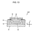
- Fig. 13 shows a sectional view of conventional acceleration sensor 5001 disclosed in Patent Document 1.
- Acceleration sensor 5001 comprises the following elements: mount substrate 61, base glass 62 placed on mount substrate 61, flexible substrate 63 placed on base glass 62, weight 64 placed on a lower surface of flexible substrate 63.
- Glass substrate 65 is placed above flexible substrate 63 to face flexible substrate 63.
- Opposed electrodes 66 placed on respective surfaces of flexible substrate 63 and glass substrate 65 facing each other.
- Weight 64 placed on the lower surface of flexible substrate 63 is movable.
- acceleration sensor 5001 An operation of acceleration sensor 5001 will be described below.
- An acceleration applied to sensor 5001 urges weight 64 along the direction of the acceleration, and causes flexible substrate 63 having weight 64 attached thereon to warp, thereby displacing flexible substrate 63.
- This displacement changes the distance between flexible substrate 63 and glass substrate 65, accordingly changing a capacitance between opposed electrodes 66.
- the sensor detects the acceleration based on the change in the capacitance due to the change in the distance between electrodes 66.
- Acceleration sensor 5001 is oriented along the direction of the acceleration to be sensed in an attitude control device or a navigation system of mobile carriers, such as vehicles.
- Acceleration sensor 5001 detects the acceleration based on the change in the capacitance between opposed electrodes 66.
- Weight 64 is placed on the lower surface of flexible substrate 63 and located above away from mount substrate 61. This arrangement causes weight 64 to be displaced easily in a direction of a Z-axis along which weight 64 and mount substrate 61 are arranged.
- Patent Document 1 JP10-177034A
- the document US 5,806,365 discloses an acceleration sensor having a mount section to be fixed to an object; a flexible section coupled to the mount section; a weight coupled to the mount section via the flexible section; a first opposed electrode unit comprising a first electrode on the weight and a second electrode facing the first electrode, to form a first capacitance, a second opposed electrode unit comprising a third electrode on the weight and a fourth electrode facing the third electrode to form a second capacitance.
- the first and second electrode units are configured to measure a component of acceleration in a first direction, based on the values of the first and second capacitances.
- the first and second electrode unit capacitor plates face each other in a direction perpendicular to.the first direction.
- a control voltage is applied to the first and second electrode units, the control voltage being changed when the capacitance simultaneously either increase or decrease.
- the document JP 4 278 464 discloses a variable capacitance accelerometer where a control voltage is applied whose magnitude varies if the differential capacitances all either increase or decrease.
- An acceleration sensor includes a mount section arranged to be fixed to an object, a flexible section coupled to the mount section, a weight coupled to the mount section via the flexible section, and first and second opposed electrode unit.
- the first opposed electrode unit includes a first electrode placed on the weight and a second electrode spaced away from and facing the first electrode, and provides a first capacitance.
- the second opposed electrode unit includes a third electrode placed on the weight and a fourth electrode spaced away from and facing the third electrode, and provides a second capacitance.
- the first and third electrodes are arranged along a first direction.
- the second and fourth electrodes are spaced away from and face the first and third electrodes along a second direction perpendicular to the first direction, respectively.
- a component of an acceleration along the first direction applied to the object is detected based on the first and second capacitances.
- a control voltage is applied to the first and second opposed electrode units. The control voltage is changed when both of the first capacitance and the second capacitance simultaneously increase or decrease.
- This acceleration sensor detects the acceleration accurately.
- Fig. 1 is an exploded perspective view of sensor element 1 of acceleration sensor 1001 in accordance with an exemplary embodiment of the present invention.
- Fig. 2 is a cross-sectional view of sensor element 1 at line 2-2 shown in Fig. 1 .
- Acceleration sensor 1001 includes sensor element 1 and processor 501 connected to sensor element 1, and detects an acceleration applied to object 1002.
- Fig. 1 directions in parallel with an X-axis, a Z-axis, and a Y-axis are defined as first, second, and third directions perpendicular to each other, respectively.
- Sensor element 1 is fixed to object 1002.
- Two arms 8 extend from supporter 12 in parallel with the X-axis and are connected with mount section 4 having a frame shape.
- Supporter 12 is coupled to mount section 4 via arm 8.
- Mount section 4 is fixed to object 1002.
- Four arms 10A to 10D extend from supporter 12 in parallel with the Y-axis, and are connect with four weights 2A to 2D, respectively.
- Arms 8 and 10A to 10D are flexible. Arms 8 and 10A to 10D and supporter 12 provides a flexible section connected with mount section 4.
- Electrodes 14A, 16A, 18A, and 20A are provided on weights 2A, 2B, 2C, and 2D, respectively.
- Mount section 4 is mounted to substrate 6 on which electrodes 14B, 16B, 18B, and 20B are placed. Electrodes 14B, 16B, 18B, and 20B are spaced away from and electrodes 14A, 16A, 18A, and 20A in parallel with the Z-axis, respectively. Electrodes 14A and 14B provide opposed electrode unit 14 having a capacitance between the electrodes. Electrodes 16A and 16B provide opposed electrode unit 16 having a capacitance between the electrodes. Electrodes 18A and 18B provide opposed electrode unit 18 having a capacitance between the electrodes. Electrodes 20A and 20B provide opposed electrode unit 20 having a capacitance between the electrodes.
- Electrodes 16A and 20A are arranged in parallel with the Y-axis. Electrodes 16B and 20B are arranged in parallel with the Y-axis. In other words, opposed electrode units 16 and 20 are arranged in parallel with the Y-axis. Arm 8 is much thinner than arms 10A to 10D, so that arm 8 has greater flexibility than arms 10A to 10D.
- Arm 10A extending from supporter 12 has substantially a U-shape including extension 110A extending from supporter 12 in parallel with the Y-axis, extension 310A extending in parallel with extension 110A in parallel with the Y-axis, and coupler 210A coupling extension 110A to extension 310A. Coupler 210A extends from extension 110A in parallel with the X-axis. Extension 310A is connected with weight 2A. Arm 10B extending from supporter 12 has substantially a U-shape including extension 110B extending from supporter 12 in parallel with the Y-axis, extension 310B extending in parallel with extension 110B in parallel with the Y-axis, and coupler 210B coupling extension 110B to extension 310B.
- Coupler 210B extends from extension 110B in parallel with the X-axis in a direction opposite to coupler 210A of arm 10A.
- Extension 310B is connected with weight 2B.
- Arm 10C extending from supporter 12 has substantially a U-shape including extension 110C extending from supporter 12 in parallel with the Y-axis, extension 310C extending in parallel with extension 110B in parallel with the Y-axis, and coupler 210C coupling extension 110C to extension 310C.
- Coupler 210C extends from extension 110C in parallel with X-axis and in parallel with coupler 210A.
- Extension 310C is connected with weight 2C.
- Arm 10D extending from supporter 12 has substantially a U-shape including extension 110D extending from supporter 12 in parallel with the Y-axis, extension 310D extending in parallel with extension 110D in parallel with the Y-axis, and coupler 210D coupling extension 110D to extension 310D.
- Coupler 210D extends from extension 110D in parallel with the X-axis in a direction opposite to coupler 210C of arm 10C.
- Extension 310D is connected with weight 2D.
- Arm 8 and supporter 12 are arranged substantially on a straight line. Extensions 110A and 110B of arms 10A and 10B extend from supporter 12 in the same direction. Extensions 110C and 110D of arms 10C and 10D extend from supporter 12 in the same direction opposite to extensions 110A and 110B. Arm 8 is symmetrical with respect to the center of sensor element 1. Arms 10A to 10D are symmetrically arranged with respect to the center of sensor element 1.
- Driving electrode 22 causing weight 2C to vibrate is provided on arm 10C.
- Sensing electrode 24 detecting vibration of arm 10D is provided on arm 10D.
- Detecting electrodes 26 and 28 detecting distortion of arms 10A and 10B are provided on arms 10A and 10B, respectively.
- electrodes 14A and 16A and detecting electrodes 26 and 28 include lower electrodes 34 formed on weights 2A and 2B and arms 10A and 10B, piezoelectric layers 30 formed on lower electrodes 34, and upper electrodes 32 formed on piezoelectric layers 30.
- electrodes 18A and 20A, driving electrode 22, and sensing electrode 24 include lower electrodes formed on weights 2C and 2D and arms 10C and 10D, piezoelectric layers formed on the lower electrodes, and upper electrodes formed on the piezoelectric layers.
- Electrodes 14A, 16A, 18A, and 20A do not necessarily include piezoelectric layer 30 or upper electrode 32. In this case, electrodes 14A, 16A, 18A, and 20A includes only lower electrodes 34 provided on weights 2A, 2B, 2C, and 2D, respectively.
- Substrate 6, mount section 4, arm 8, arms 10A to 10D, and weights 2A to 2D are unitarily made of silicon-based material, such as glass, or material having a linear expansion coefficient close to that of silicon.
- Substrate 6 is directly bonded and fixed to mount section 4.
- Substrate 6 can be bonded to mount section 4 with adhesive or bumps; however, the direct bonding maintains an accurate distance between substrate 6 and each of weights 2A to 2D without considering the thickness of the adhesive or bumps.
- Acceleration sensor 1001 can detect an angular velocity as well. An operation of sensor element 1 of sensor 1001 detecting an angular velocity will be described below.
- Fig. 3 is a perspective view of sensor element 1. Arm 10C extending from supporter 12 and weight 2C connected to arm 10C have a resonance frequency intrinsic to arm 10C and weight 2C. An alternating-current (AC) voltage having this resonance frequency is applied between the upper electrode and the lower electrode of driving electrode 22 by a driving power supply so as to deflect arm 10C, thereby causing weight 2C to vibrate with the resonance frequency in direction 901C in parallel with the X-axis.
- AC alternating-current
- Arms 10A, 10B, and 10D, and weights 2A, 2B, and 2D connected with arms 10A, 10B, and 10D, respectively, have a resonance frequency identical to the resonance frequency of arm 10C and weight 2C. Since supporter 12 is coupled to mount section 4 via flexible arm 8, the vibration of arm 10C and weight 2C at the resonance frequency transmits to arms 10A, 10B, and 10D via supporter 12, thereby causing weights 2A, 2B, and 2D to vibrate at the resonance frequency in directions 901A, 901B, and 901D, respectively in parallel with the X-axis. Sensing electrode 24 feeds back a voltage changing according to the vibration of arm 10D to the driving power supply.
- the driving power supply determines a voltage, a frequency, and a phase of the AC voltage to be applied to driving electrode 22 so as to cause arm 10D to vibrate by a predetermined amplitude. This operation causes arms 10A to 10D to vibrate at the resonance frequency by a constant amplitude.
- Weights 2A to 2D vibrate in directions 901A to 901D in parallel with the X-axis, respectively.
- the vibration of weights 2A to 2D produces a Coriolis force on weights 2A to 2D in directions 902A to 902D in parallel with the Y-axis, respectively, namely in a direction perpendicular to directions 901A to 901D.
- the Coriolis force produces a distortion on arms 10A to 10D.
- Detecting electrodes 26 and 28 output voltages in response to the distortion produced on arms 10A and 10B, hence detecting angular velocity 2001 based on the output voltages.
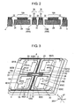
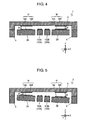
- FIGs. 4 and 5 are sectional views of sensor element 1.
- distance d1 between electrodes 14A and 14B is equal to distance d2 between electrodes 16A and 16B, as shown in Fig. 4 .
- the distance between electrodes 18A and 18B is equal to the distance between electrodes 20A and 20B.
- distance d1 between electrodes 14A and 14B decreases, while distance d2 between electrodes 16A and 16B increases, so that the capacitance of opposed electrode unit 14 increases while the capacitance of opposed electrode unit 16 decreases.
- the acceleration can be detected based on the changes of electrostatic capacitances.
- the distance between electrodes 18A and 18B decreases while the distance between electrodes 20A and 20B increases, so that the capacitance of opposed electrode unit 18 increases while the capacitance of opposed electrode unit 20 decreases.
- the acceleration can be detected also based on the changes of these capacitances.
- distance d1 between electrodes 14A and 14B increases while distance d2 between electrodes 16A and 16B decreases, so that the capacitance of opposed electrode unit 14 decreases while the capacitance of opposed electrode unit 16 increases.
- the acceleration can be detected based on the changes of these capacitances.
- the distance between electrodes 18A and 18B increases while the distance between electrodes 20A and 20B decreases, so that the capacitance of opposed electrode unit 18 decreases while the capacitance of opposed electrode unit 20 increases.
- the acceleration can be detected also based on the changes of these capacitances.
- distance d1 between electrodes 14A and 14B decreases, while distance d2 between electrodes 18A and 18B increases, so that the capacitance of opposed electrode unit 14 increases while the capacitance of opposed electrode unit 18 decreases.
- the acceleration can be detected based on the changes of the capacitances.
- distance d2 between electrodes 16A and 16B decreases while the distance between electrodes 20A and 20B increases, so that the capacitance of opposed electrode unit 16 increases while the capacitance of opposed electrode unit 20 decreases.
- the acceleration can be detected also based on the changes of these capacitances.
- distance d1 between electrodes 14A and 14B increases while the distance between electrodes 18A and 18B decreases, so that the capacitance of opposed electrode unit 14 decreases while the capacitance of opposed electrode unit 18 increases.
- the acceleration can be detected based on the changes of these capacitances.
- distance d2 between electrodes 16A and 16B increases while the distance between electrodes 20A and 20B decreases, so that the capacitance of opposed electrode unit 16 decreases while the capacitance of opposed electrode unit 20 increases.
- the acceleration can be detected also based on the changes of these capacitances.
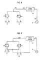
- Fig. 6 is a circuit diagram of a part of acceleration sensor 1001. Electrode 14A and electrode 16A of opposed electrode units 14 and 16 are connected to each other. Reference voltage generator 21 generates a predetermined reference voltage Vref, an AC voltage having angular frequency ⁇ . Voltage controller 23 applies reference voltage Vref to electrodes 14A and 16A. When no acceleration is applied to sensor element 1, distance d is kept between electrodes 14A and 14B, between electrodes 16A and 16B, between electrodes 18A and 18B, and between electrodes 20A and 20B. Each of electrodes 14A, 14B, 16A, and 16B has area S.
- Differential current Iref which is a difference between a current flowing through opposed electrode unit 14 and a current flowing through opposed electrode unit 16 is expressed as Equation 1 based on dielectric constant ⁇ of spaces between electrodes 14A and 14B and between electrodes 16A and 16B, displacement ⁇ of electrodes 14A and 16A in parallel with the Z-axis due to the acceleration, and angular frequency ⁇ of reference voltage Vref.
- Fig. 7 is a circuit diagram of a part of acceleration sensor 1001.
- voltage controller 23 applies control voltage V higher than reference voltage Vref across the electrodes.
- voltage controller 23 applies control voltage V lower than reference voltage Vref across the electrodes.
- Control voltage V is an AC voltage having angular frequency ⁇ identical to that of reference voltage Vref.
- Reference current Ib0 which is the sum of currents flowing through opposed electrode units 14 and 16 is expressed as Equation 2.
- Reference current Ib which is the sum of currents flowing through opposed electrode units 14 and 16 when distance d changes by displacement ⁇ is expressed as Equation 3.
- Equation 4 is obtained by Equations 2 and 3.
- ⁇ 0 / Ib d + ⁇ / d
- Sensing current Iv which is a difference between the currents flowing through opposed electrodes units 14 and 16 having control voltage V is applied thereto is expressed as Equation 5.
- Control voltage V is determined such that differential current Iref obtained when distance d is kept between electrodes 14A and 14B and between electrodes 16A and 16B is equal to sensing current Iv obtained when distance (d+ ⁇ ) is kept between electrodes 14A and 14B and between electrodes 16A and 16B.
- Iv Iref
- Equations 1 and 5 are substituted in Equation 6 to provide control voltage V as Equation 7.
- V / d + ⁇ 2 Vref / d 2
- Control voltage V obtained by Equation 7 is applied to opposed electrode units 14 and 16, thereby making differential current Iref equal to sensing current Iv. Even when distances d between electrodes 14A and 14B, between electrodes 16A and 16B, between electrodes 18A and 18B, and between electrodes 20A and 20B changes by displacement ⁇ , acceleration sensor 1001 detects the acceleration accurately similarly to the acceleration regardless of the changes of the distances.
- Acceleration sensor 1001 can accurately detect the acceleration in parallel with the X-axis applied to sensor element 1, based sensing current Iv obtained from control voltage V. Similarly, acceleration sensor 1001 can accurately detect the acceleration in parallel with the Y-axis applied to sensor element 1, based on sensing current Iv which is a difference between the currents flowing through opposed electrode units 14 and 16.
- a voltage applied to the opposed electrode units affects the acceleration.
- the acceleration detected based on the sensing current is larger than an actual acceleration when a voltage applied to the opposed electrode units is high.
- the acceleration detected based on the sensing current is smaller than the actual acceleration when a voltage applied to the opposed electrode units is low.
- the electrostatic capacitances change not by the acceleration in parallel with the X-axis or the Y-axis but by the acceleration in parallel with the Z-axis due to vibration.
- the acceleration detected based on the sensing current is smaller than an actual acceleration.
- the acceleration detected based on the sensing current is larger than an actual acceleration.
- Control voltage V applied to opposed electrode units 14, 16, 18, and 20 allows acceleration sensor 1001 to accurately detect the acceleration in parallel with the X-axis and the Y-axis even when the capacitances change due to the acceleration in parallel with the Z-axis
- the acceleration in parallel with the X-axis can be detected based on the sum of the capacitances of opposed electrode units 16 and 18 together with the sum of the capacitances of opposed electrode units 14 and 20.
- the acceleration in parallel with the Y-axis can be detected based on the sum of the capacitances of opposed electrode units 18 and 20 together with the sum of the capacitances of opposed electrode units 14 and 16.
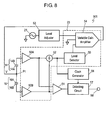
- Fig. 8 is a block diagram of processor 501 of acceleration sensor 1001.
- voltage controller 23 applies control voltage V to electrode 14A of opposed electrode unit 14 and electrode 16A of opposed electrode unit 16.
- Voltage controller 23 produces control voltage V based on reference voltage Vref supplied from reference voltage generator 21.
- An operation of voltage controller 23 is described below.
- An output port of reference voltage generator 21 is connected to level adjuster 53.
- Level adjuster 21 adjusts the amplitude of voltage Vref, and supplies voltage Vref to variable gain amplifier (VGA) 54.
- An output port of VGA 54 is connected to node P1 at which electrode 14A is connected to electrode 16A.
- CV converter amplifiers 50A and 50B output voltages in response to currents flowing through each of opposed electrode units 14 and 16, respectively. These currents change in response to the capacitances of the opposed electrode units, so that CV converter amplifiers 50A and 50B output voltages in response to the capacitances of opposed electrode units 14 and 16.
- Adder 52 adds the voltage output from amplifier 50A with the voltage output from amplifier 50B.
- Adder 52 outputs a voltage to level detector 55.
- Level detector 55 detects a level of the voltage.
- Level detector 55 can be implemented by a DC converter or a full-wave rectifier to smooth a voltage input thereto, and output a stable voltage, such as a direct-current (DC) voltage.
- An output port of level detector 55 is connected to VGA 54 for controlling a gain of VGA 54.
- VGA 54 changes the amplitude of reference voltage Vref by the gain determined in response to the output from level detector 55, i.e., in response to the reference current which is the sum of currents flowing through opposed electrode units 14 and 16.
- VGA 54 then outputs control voltage V determined by Equation 7 to opposed voltage units 14 and 16.
- Clock generator 56 generates a clock signal synchronized with control voltage V, i.e. reference voltage Vref based on the output from adder 52.
- Differential amplifier 51 outputs a difference between respective outputs of CV converter amplifiers 50A and 50B.
- the output from amplifier 51 contains a component corresponding to the acceleration in parallel with the X-axis.
- Detecting circuit 57 detects the output from differential amplifier 51 at a timing of the clock signal, and extracts the component corresponding to the acceleration. Detecting circuit 57 smoothes the component and outputs the smoothed component from output terminal 58.
- processor 501 detects a component of the acceleration of object 1002 in parallel with the X-axis based on the capacitances of opposed electrode units 14 and 16.
- Processor 501 applies control voltage V to opposed electrode units 14 and 16, and changes voltage V when the capacitance of opposed electrode units 14 and 16 increase simultaneously or decrease simultaneously.
- processor 501 increases control voltage V.
- processor 501 reduces control voltage V.
- Processor 501 detects a component of the acceleration in parallel with the Y-axis based on the capacitances of opposed electrode units 14 and 18. Circuit 501 applies control voltage V to opposed electrode units 14, 16, and 18, and changes voltage V when the capacitances of opposed electrode units 14, 16, and 18 increase simultaneously or decrease simultaneously. When the capacitances of opposed electrode units 14, 16, and 18 decrease simultaneously, processor 501 increases control voltage V. When the capacitances of opposed electrode units 14, 16, and 18 increase simultaneously greater, processor 501 reduces control voltage V.
- Processor 501 can detect the component of the acceleration in parallel with the X-axis based on the sum of capacitances of opposed electrode units 14 and 18 together with the sum of the capacitances of opposed electrode units 16 and 20. In this case, processor 501 applies control voltage V to opposed electrode units 14, 16, 18 and 20. Processor 501 changes voltage V when the capacitances of opposed electrode units 14, 16, 18, and 20 increase simultaneously or decrease simultaneously. When the capacitances of opposed electrode units 14, 16, 18, and 20 decrease simultaneously, processor 501 increases control voltage V. When the capacitances of opposed electrode units 14, 16, 18, and 20 decreases simultaneously, processor 501 reduces control voltage V.
- Processor 501 can detect the component of the acceleration in parallel with the Y-axis based on the sum of capacitances of opposed electrode units 14 and 16 together with the sum of the capacitances of opposed electrode units 18 and 20.
- sensor element 1 in accordance with this embodiment, four opposed electrode units 14, 16, 18, and 20 are placed at four corners of a rectangle. Opposed electrode units 14 and 16 are arranged in parallel with the X-axis, and opposed electrode units 18 and 20 are arranged also in parallel with the X-axis. Opposed electrode units 14 and 18 are arranged in parallel with the Y-axis, and opposed electrode units 16 and 20 are arranged also in parallel with the Y-axis.
- four opposed electrode units 14, 16, 18, and 20 of in sensor element 1 serve both as opposed electrode units arranged in parallel with the X-axis and as opposed electrode units arranged in parallel with the Y-axis.
- Fig. 9 is an exploded perspective view of sensor element 1A of another acceleration sensor in accordance with this embodiment.
- Sensor element 1A shown in Fig. 9 includes opposed electrode units 114, 116, 118, 120, 214, 216, 218, and 220 instead of opposed electrode units 14, 16, 18, and 20 of sensor element 1 shown in Fig. 1 .
- Opposed electrode unit 114 includes electrode 114A placed on weight 2A and electrode 114B placed on substrate 6. Electrode 114A is spaced away from and faces electrode 114B in parallel with the Z-axis.
- Opposed electrode unit 214 includes electrode 214A placed on weight 2A and electrode 214B placed on substrate 6. Electrode 214A is spaced away from and faces electrode 214B in parallel with the Z-axis.
- Opposed electrode unit 116 includes electrode 116A placed on weight 2B and electrode 116B placed on substrate 6. Electrode 116A is spaced away from and faces electrode 116B in parallel with the Z-axis.
- Opposed electrode unit 216 includes electrode 216A placed on weight 2B and electrode 216B placed on substrate 6. Electrode 216A is spaced away from and faces electrode 216B in parallel with the Z-axis.
- Opposed electrode unit 118 includes electrode 118A placed on weight 2C and electrode 118B placed on substrate 6.
- Electrode 118A is spaced away from and faces electrode 118B in parallel with the Z-axis.
- Opposed electrode unit 218 includes electrode 218A placed on weight 2C and electrode 218B placed on substrate 6. Electrode 218A is spaced away from and faces electrode 218B in parallel with the Z-axis.
- Opposed electrode unit 120 includes electrode 120A placed on weight 2D and electrode 120B placed on substrate 6. Electrode 120A is spaced away from and faces electrode 120B in parallel with the Z-axis.
- Opposed electrode unit 220 includes electrode 220A placed on weight 2D and electrode 220B placed on substrate 6. Electrode 220A is spaced away from and faces electrode 220B in parallel with the Z-axis.
- Opposed electrode units 114 and 116 are arranged in parallel with the X-axis.
- Opposed electrode units 118 and 120 are arranged also in parallel with the X-axis.
- Opposed electrode units 214 and 218 are arranged in parallel with the Y-axis.
- Opposed electrode units 216 and 220 are arranged also in parallel with the Y-axis.
- sensor element 1A includes the opposed electrode units arranged in parallel with the X-axis independent from the opposed electrode units arranged in parallel with the Y-axis, but operates similarly to sensor element 1 and provides the same effects.
- Processor 501 detects the component of the acceleration in parallel with the X-axis based on capacitances of opposed electrode units 114 and 116, and detects the component of the acceleration in parallel with the Y-axis based on capacitances of opposed electrode units 214 and 218.
- Processor 501 applies control voltage V to opposed electrode units 114, 116, 214, and 218, and changes voltage V when the capacitances of opposed electrode units 114, 116, 214, and 218 simultaneously decreases or simultaneously increase.
- processor 501 increases control voltage V.
- processor 501 reduces control voltage V.
- Processor 501 can detect the component of the acceleration in parallel with the X-axis based on the sum of the capacitances of opposed electrode units 114 and 116 together with the sum of the capacitances of opposed electrode units 118 and 120.
- Processor 501 can detect the component of the acceleration in parallel with the Y-axis based on the sum of the capacitance of opposed electrode units 214 and 216 together with the sum of the capacitances of opposed electrode units 218 and 220.
- processor 501 applies control voltage V to opposed electrode units 114, 116, 118, 120, 214, 216, 218, and 220, and changes control voltage V when the capacitances of all of these opposed electrode units simultaneously decrease or simultaneously increase.
- processor 501 increases control voltage V.
- processor 501 reduces control voltage V.
- Sensor element 1 shown in Fig. 1 includes weights 2A, 2B, 2C, and 2D having electrodes 14A, 16A, 18A, and 20A thereon, respectively. The number of those weights is not limited to four.
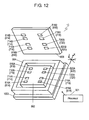
- Fig. 10 is an exploded perspective view of sensor element 1B of a further acceleration sensor in accordance with this embodiment.
- Fig. 11 is a sectional view of sensor element 1B shown in Fig. 10 .
- Sensor element 1B is fixed to object 1003 having an acceleration to be detected.
- Sensor element 1B includes mount section 604 fixed to object 1003, weight 602, flexible section 610 which couples weight 602 to mount section 604.
- Mount section 604 has a frame shape surrounding flexible section 610 and weight 602, and is mounted to substrate 606. Electrodes 614A, 616A, 618A, and 620A are placed on weight 602.
- Electrodes 614B, 616B, 618B, and 620B placed on substrate 606 are spaced away from and face electrodes 614A, 614B, 614C, and 614D in parallel with the Z-axis, respectively. Electrodes 614A and 614B form opposed electrode unit 614 having a capacitance between electrodes 614A and 614B. Electrodes 616A and 616B form opposed electrode unit 616 having a capacitance between electrodes 616A and 616B. Electrodes 618A and 618B form opposed electrode unit 618 having a capacitance between electrodes 618A and 618B. Electrodes 620A and 620B form opposed electrode unit 620 having a capacitance between electrodes 620A and 620B.
- Electrodes 614A and 616A are arranged in parallel with the X-axis. Electrodes 614B and 616B are arranged also in parallel with the X-axis. In other words, opposed electrode units 614 and 616 are arranged in parallel with the X-axis. Electrodes 618A and 620A are arranged in parallel with the X-axis. Electrodes 618B and 620B are arranged also in parallel with the X-axis. In other words, opposed electrode units 618 and 620 are arranged in parallel with the X-axis. Electrodes 614A and 618A are arranged in parallel with the Y-axis. Electrodes 614B and 618B are arranged also in parallel with the Y-axis.
- Electrodes 614 and 618 are arranged in parallel with the Y-axis. Electrodes 616A and 620A are arranged in parallel with the Y-axis. Electrodes 616B and 620B are arranged also in parallel with the Y-axis. In other words, opposed electrode units 616 and 620 are arranged in parallel with the Y-axis.
- Electrodes 614A, 616A, 618A, and 620A are displaced by the acceleration, similarly to the displacement of electrodes 14A, 16A, 18A and 20A of sensor element 1 shown in Fig. 1 .
- opposed electrode units 614, 616, 618 and 620 of sensor element 1B operate similarly to opposed electrode units 14, 16, 18 and 20 of sensor element 1 shown in Fig. 1 .
- Processor 501 shown in Fig. 8 is connected to opposed electrode units 614, 616, 618 and 620 of sensor element 1B instead of opposed electrode units 14, 16, 18 and 20 of sensor element 1 so as to detect the acceleration accurately.
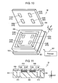
- Fig. 12 is an exploded perspective view of sensor element 1C of a further acceleration sensor in accordance with this embodiment.
- Sensor element 1C shown in Fig. 12 includes opposed electrode units 714, 716, 718, 720, 814, 816, 818, and 820 instead of opposed electrode units 614, 616, 618, and 620 of sensor element 1B shown in Fig. 10 .
- Opposed electrode unit 714 includes electrode 714A placed on weight 602 and electrode 714B placed on substrate 606. Electrode 714A is spaced away from and faces electrode 714B in parallel with the Z-axis.
- Opposed electrode unit 814 includes electrode 814A placed on weight 602 and electrode 814B placed on substrate 606. Electrode 814A is spaced away from and faces electrode 814B in parallel with the Z-axis.
- Opposed electrode unit 716 includes electrode 716A placed on weight 602 and electrode 716B placed on substrate 606. Electrode 716A is spaced away from and faces electrode 716B in parallel with the Z-axis.
- Opposed electrode unit 816 includes electrode 816A placed on weight 602 and electrode 816B placed on substrate 606. Electrode 816A is spaced away from and faces electrode 816B in parallel with the Z-axis.
- Opposed electrode unit 718 includes electrode 718A placed on weight 602 and electrode 718B placed on substrate 606.
- Electrode 718A is spaced away from and faces electrode 718B in parallel with the Z-axis.
- Opposed electrode unit 818 includes electrode 818A placed on weight 602 and electrode 818B placed on substrate 606. Electrode 818A is spaced away from and faces electrode 818B in parallel with the Z-axis.
- Opposed electrode unit 720 includes electrode 720A placed on weight 602 and electrode 720B placed on substrate 606. Electrode 720A is spaced away from and faces electrode 720B in parallel with the Z-axis.
- Opposed electrode unit 820 includes electrode 820A placed on weight 602 and electrode 820B placed on substrate 606. Electrode 820A is spaced away from and faces electrode 820B in parallel with the Z-axis.
- Opposed electrode units 714 and 716 are arranged in parallel with the X-axis.
- Opposed electrode units 718 and 720 are arranged in parallel with the X-axis.
- Opposed electrode units 814 and 818 are arranged in parallel with the Y-axis.
- Opposed electrode units 816 and 820 are arranged in parallel with the Y-axis.
- sensor element 1C has opposed electrode units arranged in parallel with the X-axis independent of opposed electrode units arrange in parallel with the Y-axis, but operates similarly and provides the same effects.
- An acceleration sensor detects an acceleration accurately, and is useful for various electronic devices which perform attitude-control or navigation for mobile carriers such as airplanes, cars, robots, vessels, or vehicles.
Landscapes
- Physics & Mathematics (AREA)
- General Physics & Mathematics (AREA)
- Pressure Sensors (AREA)
- Switches Operated By Changes In Physical Conditions (AREA)
Applications Claiming Priority (2)
| Application Number | Priority Date | Filing Date | Title |
|---|---|---|---|
| JP2007059449A JP5631529B2 (ja) | 2007-03-09 | 2007-03-09 | 加速度センサ |
| PCT/JP2008/000458 WO2008111291A1 (ja) | 2007-03-09 | 2008-03-06 | 加速度センサ |
Publications (3)
| Publication Number | Publication Date |
|---|---|
| EP2110672A1 EP2110672A1 (en) | 2009-10-21 |
| EP2110672A4 EP2110672A4 (en) | 2012-04-04 |
| EP2110672B1 true EP2110672B1 (en) | 2013-02-27 |
Family
ID=39759235
Family Applications (1)
| Application Number | Title | Priority Date | Filing Date |
|---|---|---|---|
| EP08720344A Active EP2110672B1 (en) | 2007-03-09 | 2008-03-06 | Acceleration sensor |
Country Status (4)
| Country | Link |
|---|---|
| US (1) | US8413510B2 (enExample) |
| EP (1) | EP2110672B1 (enExample) |
| JP (1) | JP5631529B2 (enExample) |
| WO (1) | WO2008111291A1 (enExample) |
Families Citing this family (4)
| Publication number | Priority date | Publication date | Assignee | Title |
|---|---|---|---|---|
| US8201449B2 (en) * | 2006-11-14 | 2012-06-19 | Panasonic Corporation | Sensor |
| WO2008102535A1 (ja) * | 2007-02-20 | 2008-08-28 | Panasonic Corporation | 慣性力センサおよび複合慣性力センサ |
| DE102009001847B4 (de) | 2009-03-25 | 2022-07-28 | Robert Bosch Gmbh | Mikromechanisches Bauteil, Sensorvorrichtung mit einem mikromechanischen Bauteil und Verfahren zum Betreiben eines mikromechanischen Bauteils |
| EP3429523B1 (en) | 2016-03-15 | 2019-12-25 | The Procter and Gamble Company | Method and apparatus for manufacturing an absorbent article including an ultra short pulse laser source |
Family Cites Families (9)
| Publication number | Priority date | Publication date | Assignee | Title |
|---|---|---|---|---|
| JP2773460B2 (ja) * | 1991-03-05 | 1998-07-09 | 日本電気株式会社 | 半導体加速度センサ |
| JP3124710B2 (ja) | 1995-07-28 | 2001-01-15 | 住友精密工業株式会社 | 静電容量の変化を利用したセンサ用信号処理回路 |
| JPH09196682A (ja) * | 1996-01-19 | 1997-07-31 | Matsushita Electric Ind Co Ltd | 角速度センサと加速度センサ |
| US5806365A (en) | 1996-04-30 | 1998-09-15 | Motorola, Inc. | Acceleration sensing device on a support substrate and method of operation |
| JPH10177034A (ja) | 1996-12-17 | 1998-06-30 | Sumitomo Precision Prod Co Ltd | 静電容量型加速度センサとその製造方法 |
| JPH11248741A (ja) * | 1998-02-26 | 1999-09-17 | Omron Corp | 静電容量型多軸加速度センサ |
| WO2002018875A1 (en) * | 2000-08-30 | 2002-03-07 | Matsushita Electric Industrial Co., Ltd. | Angular velocity sensor |
| US20030033850A1 (en) * | 2001-08-09 | 2003-02-20 | Challoner A. Dorian | Cloverleaf microgyroscope with electrostatic alignment and tuning |
| US6910379B2 (en) * | 2003-10-29 | 2005-06-28 | Honeywell International, Inc. | Out-of-plane compensation suspension for an accelerometer |
-
2007
- 2007-03-09 JP JP2007059449A patent/JP5631529B2/ja active Active
-
2008
- 2008-03-06 US US12/529,675 patent/US8413510B2/en active Active
- 2008-03-06 EP EP08720344A patent/EP2110672B1/en active Active
- 2008-03-06 WO PCT/JP2008/000458 patent/WO2008111291A1/ja not_active Ceased
Also Published As
| Publication number | Publication date |
|---|---|
| US20100107764A1 (en) | 2010-05-06 |
| JP2008224262A (ja) | 2008-09-25 |
| JP5631529B2 (ja) | 2014-11-26 |
| WO2008111291A1 (ja) | 2008-09-18 |
| US8413510B2 (en) | 2013-04-09 |
| EP2110672A1 (en) | 2009-10-21 |
| EP2110672A4 (en) | 2012-04-04 |
Similar Documents
| Publication | Publication Date | Title |
|---|---|---|
| CN1954188B (zh) | 陀螺仪传感器和使用该陀螺仪传感器的传感器装置 | |
| US9874459B2 (en) | Actuation and sensing platform for sensor calibration and vibration isolation | |
| US8096181B2 (en) | Inertial sensor | |
| US6504356B2 (en) | Microelectro-mechanical high resolution current sensing apparatus | |
| EP0497289B1 (en) | A capacitive angular acceleration sensor | |
| US8250916B2 (en) | Inertial sensor | |
| US8836348B2 (en) | Electrostatic capacitance type physical quantity sensor and angular velocity sensor | |
| CN102119318B (zh) | 微机电系统 | |
| US20100127715A1 (en) | Semiconductor physical quantity sensor and control device using the same | |
| US20100126270A1 (en) | Inertia force sensor | |
| CN107003333B (zh) | Mems传感器和半导体封装 | |
| EP2110672B1 (en) | Acceleration sensor | |
| EP3226006B1 (en) | Accelerometer sensor system | |
| WO2015069386A1 (en) | Accelerometer with offset compensation | |
| US8104344B2 (en) | Angular velocity sensor utilizing coriolis force | |
| EP3226007B1 (en) | A mems accelerometer having high accuracy and low sensitivity to temperature and ageing | |
| CN110546516B (zh) | 用于加速度计的去耦结构 | |
| US20160091526A1 (en) | Sensor | |
| US20140283606A1 (en) | Acceleration sensor | |
| JPH11248741A (ja) | 静電容量型多軸加速度センサ | |
| JP3287244B2 (ja) | 加速度検出装置 | |
| KR100880212B1 (ko) | 자이로 센서 및 이를 이용하는 센서 장치 | |
| JP3020829B2 (ja) | 多次元方向に関する力・加速度・磁気の検出装置 |
Legal Events
| Date | Code | Title | Description |
|---|---|---|---|
| PUAI | Public reference made under article 153(3) epc to a published international application that has entered the european phase |
Free format text: ORIGINAL CODE: 0009012 |
|
| 17P | Request for examination filed |
Effective date: 20090716 |
|
| AK | Designated contracting states |
Kind code of ref document: A1 Designated state(s): AT BE BG CH CY CZ DE DK EE ES FI FR GB GR HR HU IE IS IT LI LT LU LV MC MT NL NO PL PT RO SE SI SK TR |
|
| DAX | Request for extension of the european patent (deleted) | ||
| A4 | Supplementary search report drawn up and despatched |
Effective date: 20120307 |
|
| RIC1 | Information provided on ipc code assigned before grant |
Ipc: G01P 15/18 20060101ALI20120312BHEP Ipc: G01P 15/125 20060101AFI20120312BHEP Ipc: H01L 29/84 20060101ALI20120312BHEP |
|
| GRAP | Despatch of communication of intention to grant a patent |
Free format text: ORIGINAL CODE: EPIDOSNIGR1 |
|
| GRAS | Grant fee paid |
Free format text: ORIGINAL CODE: EPIDOSNIGR3 |
|
| GRAA | (expected) grant |
Free format text: ORIGINAL CODE: 0009210 |
|
| AK | Designated contracting states |
Kind code of ref document: B1 Designated state(s): AT BE BG CH CY CZ DE DK EE ES FI FR GB GR HR HU IE IS IT LI LT LU LV MC MT NL NO PL PT RO SE SI SK TR |
|
| REG | Reference to a national code |
Ref country code: GB Ref legal event code: FG4D |
|
| REG | Reference to a national code |
Ref country code: CH Ref legal event code: EP |
|
| REG | Reference to a national code |
Ref country code: AT Ref legal event code: REF Ref document number: 598764 Country of ref document: AT Kind code of ref document: T Effective date: 20130315 |
|
| REG | Reference to a national code |
Ref country code: IE Ref legal event code: FG4D |
|
| REG | Reference to a national code |
Ref country code: DE Ref legal event code: R096 Ref document number: 602008022488 Country of ref document: DE Effective date: 20130425 |
|
| REG | Reference to a national code |
Ref country code: AT Ref legal event code: MK05 Ref document number: 598764 Country of ref document: AT Kind code of ref document: T Effective date: 20130227 |
|
| REG | Reference to a national code |
Ref country code: LT Ref legal event code: MG4D |
|
| PG25 | Lapsed in a contracting state [announced via postgrant information from national office to epo] |
Ref country code: IS Free format text: LAPSE BECAUSE OF FAILURE TO SUBMIT A TRANSLATION OF THE DESCRIPTION OR TO PAY THE FEE WITHIN THE PRESCRIBED TIME-LIMIT Effective date: 20130627 Ref country code: SE Free format text: LAPSE BECAUSE OF FAILURE TO SUBMIT A TRANSLATION OF THE DESCRIPTION OR TO PAY THE FEE WITHIN THE PRESCRIBED TIME-LIMIT Effective date: 20130227 Ref country code: BG Free format text: LAPSE BECAUSE OF FAILURE TO SUBMIT A TRANSLATION OF THE DESCRIPTION OR TO PAY THE FEE WITHIN THE PRESCRIBED TIME-LIMIT Effective date: 20130527 Ref country code: NO Free format text: LAPSE BECAUSE OF FAILURE TO SUBMIT A TRANSLATION OF THE DESCRIPTION OR TO PAY THE FEE WITHIN THE PRESCRIBED TIME-LIMIT Effective date: 20130527 Ref country code: LT Free format text: LAPSE BECAUSE OF FAILURE TO SUBMIT A TRANSLATION OF THE DESCRIPTION OR TO PAY THE FEE WITHIN THE PRESCRIBED TIME-LIMIT Effective date: 20130227 Ref country code: ES Free format text: LAPSE BECAUSE OF FAILURE TO SUBMIT A TRANSLATION OF THE DESCRIPTION OR TO PAY THE FEE WITHIN THE PRESCRIBED TIME-LIMIT Effective date: 20130607 Ref country code: AT Free format text: LAPSE BECAUSE OF FAILURE TO SUBMIT A TRANSLATION OF THE DESCRIPTION OR TO PAY THE FEE WITHIN THE PRESCRIBED TIME-LIMIT Effective date: 20130227 |
|
| REG | Reference to a national code |
Ref country code: NL Ref legal event code: VDEP Effective date: 20130227 |
|
| PG25 | Lapsed in a contracting state [announced via postgrant information from national office to epo] |
Ref country code: PT Free format text: LAPSE BECAUSE OF FAILURE TO SUBMIT A TRANSLATION OF THE DESCRIPTION OR TO PAY THE FEE WITHIN THE PRESCRIBED TIME-LIMIT Effective date: 20130627 Ref country code: FI Free format text: LAPSE BECAUSE OF FAILURE TO SUBMIT A TRANSLATION OF THE DESCRIPTION OR TO PAY THE FEE WITHIN THE PRESCRIBED TIME-LIMIT Effective date: 20130227 Ref country code: SI Free format text: LAPSE BECAUSE OF FAILURE TO SUBMIT A TRANSLATION OF THE DESCRIPTION OR TO PAY THE FEE WITHIN THE PRESCRIBED TIME-LIMIT Effective date: 20130227 Ref country code: BE Free format text: LAPSE BECAUSE OF FAILURE TO SUBMIT A TRANSLATION OF THE DESCRIPTION OR TO PAY THE FEE WITHIN THE PRESCRIBED TIME-LIMIT Effective date: 20130227 Ref country code: PL Free format text: LAPSE BECAUSE OF FAILURE TO SUBMIT A TRANSLATION OF THE DESCRIPTION OR TO PAY THE FEE WITHIN THE PRESCRIBED TIME-LIMIT Effective date: 20130227 Ref country code: GR Free format text: LAPSE BECAUSE OF FAILURE TO SUBMIT A TRANSLATION OF THE DESCRIPTION OR TO PAY THE FEE WITHIN THE PRESCRIBED TIME-LIMIT Effective date: 20130528 Ref country code: LV Free format text: LAPSE BECAUSE OF FAILURE TO SUBMIT A TRANSLATION OF THE DESCRIPTION OR TO PAY THE FEE WITHIN THE PRESCRIBED TIME-LIMIT Effective date: 20130227 |
|
| PG25 | Lapsed in a contracting state [announced via postgrant information from national office to epo] |
Ref country code: HR Free format text: LAPSE BECAUSE OF FAILURE TO SUBMIT A TRANSLATION OF THE DESCRIPTION OR TO PAY THE FEE WITHIN THE PRESCRIBED TIME-LIMIT Effective date: 20130227 |
|
| PG25 | Lapsed in a contracting state [announced via postgrant information from national office to epo] |
Ref country code: CZ Free format text: LAPSE BECAUSE OF FAILURE TO SUBMIT A TRANSLATION OF THE DESCRIPTION OR TO PAY THE FEE WITHIN THE PRESCRIBED TIME-LIMIT Effective date: 20130227 Ref country code: DK Free format text: LAPSE BECAUSE OF FAILURE TO SUBMIT A TRANSLATION OF THE DESCRIPTION OR TO PAY THE FEE WITHIN THE PRESCRIBED TIME-LIMIT Effective date: 20130227 Ref country code: EE Free format text: LAPSE BECAUSE OF FAILURE TO SUBMIT A TRANSLATION OF THE DESCRIPTION OR TO PAY THE FEE WITHIN THE PRESCRIBED TIME-LIMIT Effective date: 20130227 Ref country code: NL Free format text: LAPSE BECAUSE OF FAILURE TO SUBMIT A TRANSLATION OF THE DESCRIPTION OR TO PAY THE FEE WITHIN THE PRESCRIBED TIME-LIMIT Effective date: 20130227 Ref country code: MC Free format text: LAPSE BECAUSE OF NON-PAYMENT OF DUE FEES Effective date: 20130331 Ref country code: SK Free format text: LAPSE BECAUSE OF FAILURE TO SUBMIT A TRANSLATION OF THE DESCRIPTION OR TO PAY THE FEE WITHIN THE PRESCRIBED TIME-LIMIT Effective date: 20130227 Ref country code: RO Free format text: LAPSE BECAUSE OF FAILURE TO SUBMIT A TRANSLATION OF THE DESCRIPTION OR TO PAY THE FEE WITHIN THE PRESCRIBED TIME-LIMIT Effective date: 20130227 |
|
| REG | Reference to a national code |
Ref country code: CH Ref legal event code: PL |
|
| PG25 | Lapsed in a contracting state [announced via postgrant information from national office to epo] |
Ref country code: CY Free format text: LAPSE BECAUSE OF FAILURE TO SUBMIT A TRANSLATION OF THE DESCRIPTION OR TO PAY THE FEE WITHIN THE PRESCRIBED TIME-LIMIT Effective date: 20130227 |
|
| PG25 | Lapsed in a contracting state [announced via postgrant information from national office to epo] |
Ref country code: IT Free format text: LAPSE BECAUSE OF FAILURE TO SUBMIT A TRANSLATION OF THE DESCRIPTION OR TO PAY THE FEE WITHIN THE PRESCRIBED TIME-LIMIT Effective date: 20130227 |
|
| REG | Reference to a national code |
Ref country code: IE Ref legal event code: MM4A |
|
| PLBE | No opposition filed within time limit |
Free format text: ORIGINAL CODE: 0009261 |
|
| STAA | Information on the status of an ep patent application or granted ep patent |
Free format text: STATUS: NO OPPOSITION FILED WITHIN TIME LIMIT |
|
| GBPC | Gb: european patent ceased through non-payment of renewal fee |
Effective date: 20130527 |
|
| PG25 | Lapsed in a contracting state [announced via postgrant information from national office to epo] |
Ref country code: LI Free format text: LAPSE BECAUSE OF NON-PAYMENT OF DUE FEES Effective date: 20130331 Ref country code: IE Free format text: LAPSE BECAUSE OF NON-PAYMENT OF DUE FEES Effective date: 20130306 Ref country code: CH Free format text: LAPSE BECAUSE OF NON-PAYMENT OF DUE FEES Effective date: 20130331 |
|
| 26N | No opposition filed |
Effective date: 20131128 |
|
| REG | Reference to a national code |
Ref country code: DE Ref legal event code: R097 Ref document number: 602008022488 Country of ref document: DE Effective date: 20131128 |
|
| PG25 | Lapsed in a contracting state [announced via postgrant information from national office to epo] |
Ref country code: GB Free format text: LAPSE BECAUSE OF NON-PAYMENT OF DUE FEES Effective date: 20130527 |
|
| PG25 | Lapsed in a contracting state [announced via postgrant information from national office to epo] |
Ref country code: MT Free format text: LAPSE BECAUSE OF FAILURE TO SUBMIT A TRANSLATION OF THE DESCRIPTION OR TO PAY THE FEE WITHIN THE PRESCRIBED TIME-LIMIT Effective date: 20130227 |
|
| PG25 | Lapsed in a contracting state [announced via postgrant information from national office to epo] |
Ref country code: TR Free format text: LAPSE BECAUSE OF FAILURE TO SUBMIT A TRANSLATION OF THE DESCRIPTION OR TO PAY THE FEE WITHIN THE PRESCRIBED TIME-LIMIT Effective date: 20130227 |
|
| PG25 | Lapsed in a contracting state [announced via postgrant information from national office to epo] |
Ref country code: LU Free format text: LAPSE BECAUSE OF NON-PAYMENT OF DUE FEES Effective date: 20130306 Ref country code: HU Free format text: LAPSE BECAUSE OF FAILURE TO SUBMIT A TRANSLATION OF THE DESCRIPTION OR TO PAY THE FEE WITHIN THE PRESCRIBED TIME-LIMIT; INVALID AB INITIO Effective date: 20080306 |
|
| PG25 | Lapsed in a contracting state [announced via postgrant information from national office to epo] |
Ref country code: FR Free format text: LAPSE BECAUSE OF NON-PAYMENT OF DUE FEES Effective date: 20130331 |
|
| PGFP | Annual fee paid to national office [announced via postgrant information from national office to epo] |
Ref country code: DE Payment date: 20241231 Year of fee payment: 18 |