EP2110325B1 - Unité de vanne d'arrêt d'un dispositif d'alimentation et de tri pour machines d'emballage - Google Patents
Unité de vanne d'arrêt d'un dispositif d'alimentation et de tri pour machines d'emballage Download PDFInfo
- Publication number
- EP2110325B1 EP2110325B1 EP08007417A EP08007417A EP2110325B1 EP 2110325 B1 EP2110325 B1 EP 2110325B1 EP 08007417 A EP08007417 A EP 08007417A EP 08007417 A EP08007417 A EP 08007417A EP 2110325 B1 EP2110325 B1 EP 2110325B1
- Authority
- EP
- European Patent Office
- Prior art keywords
- base plate
- slide unit
- blocking
- plate
- unit according
- Prior art date
- Legal status (The legal status is an assumption and is not a legal conclusion. Google has not performed a legal analysis and makes no representation as to the accuracy of the status listed.)
- Active
Links
Images


Classifications
-
- B—PERFORMING OPERATIONS; TRANSPORTING
- B65—CONVEYING; PACKING; STORING; HANDLING THIN OR FILAMENTARY MATERIAL
- B65B—MACHINES, APPARATUS OR DEVICES FOR, OR METHODS OF, PACKAGING ARTICLES OR MATERIALS; UNPACKING
- B65B35/00—Supplying, feeding, arranging or orientating articles to be packaged
- B65B35/06—Separating single articles from loose masses of articles
-
- B—PERFORMING OPERATIONS; TRANSPORTING
- B65—CONVEYING; PACKING; STORING; HANDLING THIN OR FILAMENTARY MATERIAL
- B65B—MACHINES, APPARATUS OR DEVICES FOR, OR METHODS OF, PACKAGING ARTICLES OR MATERIALS; UNPACKING
- B65B5/00—Packaging individual articles in containers or receptacles, e.g. bags, sacks, boxes, cartons, cans, jars
- B65B5/10—Filling containers or receptacles progressively or in stages by introducing successive articles, or layers of articles
- B65B5/101—Filling containers or receptacles progressively or in stages by introducing successive articles, or layers of articles by gravity
- B65B5/103—Filling containers or receptacles progressively or in stages by introducing successive articles, or layers of articles by gravity for packaging pills or tablets
Definitions
- the present invention relates to gate valve units of feeding and sorting apparatus for packaging machines.
- it relates to gate valves of feeding and sorting devices for tablets, capsules, dragees or the like, in particular to thermoforming machines.
- the invention is therefore based on the object to provide both a gate valve unit of feeding and sorting devices for tablets, capsules, dragees or the like to blister packs, which can be both faster and cheaper manufactured and better cleaned, and a method for faster and cheaper manufacture of the base plate for the gate valve unit to provide.
- the Absperrfinger can be made faster and cheaper with the base plate, since on the one hand no recordings for the Absperrfinger need to be made consuming with a milling device and on the other hand no Absperrfinger made in additional process steps and must be introduced.
- An additional advantage is that in the base plate the Absperrfinger can be formed during the formation of the through holes. Furthermore, the Absperrfinger hang piecewise or completely together, whereby the production of Absperrschieberussi is simplified.
- Another advantage is that the conventional recordings for the fingers can be saved, whereby a cleaning of Absperrschieberajien can be performed better and faster.
- the passage openings in the base plate are associated with a plurality of shut-off fingers.
- the base plate can be formed with the Absperrfingern of a solid material, in particular steel, aluminum or plastics, which in particular the durability and the load capacity of the feeding and sorting device can be improved.
- the base plate with the Absperrfingern have a soft coating, in particular a silicone coating. This leads to the fact that sensitive materials are sorted more gently, and on the other hand, this causes a reduction in impurities. This is an important consideration especially for medicines or food.
- the base plate is formed with the Absperrfingern of a soft material, in particular silicone.
- the base plate may include a number of sub-base plates to facilitate better handling by dividing the base plate into a number of sub-base plates.
- a second aspect of the present invention relates to a gate valve unit according to the first aspect of the invention, wherein the base plate is disposed on a lower holding plate and at least one fixing means for fixing the base plate is attached to the lower holding plate.
- the fastening means comprises a lock
- the lock actuator is assigned a release and locking recess such that by moving the lower plate to the base plate in the release and locking recess, the base plate of the lower Retained holding plate or is detected on the lower plate.
- a fast and secure attachment or release of the base plate is effected.
- the attachment via a clamping device such. B. one Plastic clipper causes. In this way, the base plate is secured against slipping during operation.
- a gate valve unit may include an upper support plate on which the base plate is disposed and to which at least one attachment means for fixing the base plate to the upper support plate is mounted, whereby the desired spacing of the base plate can be achieved.
- the fastener comprises a lock
- a release and Feststellaussparung is assigned such that by moving the base plate to the upper plate in the release and Feststellaussparung the base plate from the top Retained holding plate or is detected on the upper plate, whereby the base plate is secured against slipping during operation.
- a third aspect of the present invention relates to a gate valve assembly according to the first or second aspect of the present invention, wherein instead of the base plate there is a corresponding lower base plate with lower through holes and a corresponding upper base plate with upper through holes, the lower base plate and the upper base plate are arranged to each other such that in each case the lower passage opening and the corresponding upper passage opening are associated with a corresponding number of filling tubes.
- the gate valve unit comprises at least one guide member having a lower guide for guiding the lower base plate and an upper guide for guiding the upper base plate, wherein the at least one guide member and the lower base plate and the upper base plate between a lower cover plate and an upper cover plate are arranged ,
- the guide parts for accelerated assembly and disassembly and to simplify the cleaning in the upper cover plate and the lower cover plate plugged and thus easily determined.
- the lower base plate for the lower guide and the upper base plate for the upper guide have different corresponding codings. Due to the differences in the coding of the guides and the corresponding differences in the coding of the upper and lower base plate, a permutation of the base plates can be prevented.
- the lower base plate has a first height and the upper base plate has a second height, the first height being different from the second height, and the lower guide being a lower guide groove having a width matching the first height and the upper guide is formed as an upper guide groove having a width matching the second height. Due to the asymmetry of the dimensions, a permutation of the lower and the upper base plate during installation is prevented in a simple mechanical manner.
- a fourth aspect of the present invention relates to a gate valve unit according to the third aspect of the present invention, wherein the guide member on the top cover plate side facing a first lock and on the lower cover plate side facing a second lock in such a way that the first lock and the second lock are different, wherein on the upper cover plate on the guide part facing side, a first key to the first lock for connection to the guide member is formed and on the lower cover plate on the guide member side facing a second key to the second lock is designed for connection to the guide part.
- the first lock is formed as an upper guide projection on the top of the guide member
- the second lock is formed as a lower guide projection on the underside of the guide member
- the first key on the underside of the upper cover plate as one to the upper guide projection formed matching upper guide recess
- the second key is formed on the upper side of the lower cover plate as a matching with the lower guide projection lower guide recess.
- a fifth aspect of the present invention relates to a gate valve unit according to the third or fourth aspect of the present invention, wherein the upper base plate is movably disposed relative to the lower base plate, and an end position of the upper base plate is made adjustable.
- the gate valve unit comprises a pneumatic cylinder for moving the upper base plate and a stop for limiting the movement of the upper base plate, wherein the stopper is designed to be adjustable by a motor.
- a sixth aspect of the present invention relates to a method of manufacturing a base plate for the above-mentioned gate valve units.
- the above object is achieved in that in the base plate with the through holes, the Absperrfinger be formed integrally with the base plate.
- the base plate with the Absperrfingern can be made faster and cheaper because on the one hand no recordings for the Absperrfinger need to be made consuming with a milling device and on the other hand no Absperrfinger need to be prepared in additional process steps and introduced.
- An additional advantage is that in the base plate the Absperrfinger can be formed during the formation of the through holes.
- the base plate with the Absperrfingern of a solid material, in particular steel, aluminum or plastics are preferred educated.
- the durability and the load capacity of the gate valve unit are improved.
- the base plate with the Absperrfingern of a soft material, in particular silicone formed is arranged. This leads to the fact that sensitive materials are sorted more gently, and on the other hand, this causes a reduction in impurities. This is an important consideration especially for medicines or food.
- punching methods casting methods, spraying methods, laser methods or rapid prototyping methods can also be used in the method.
- two of these Absperrschieberritten are interconnected such that their passage openings are congruent to each other, wherein the Absperrschieberussien the Absperrfinger are arranged differently, so that the respective through holes associated Absperrfinger the Absperrschieberussien are each arranged offset from one another.
- the processing speed can be increased.
- the gate valve unit comprises a lower base plate according to one of the preceding aspects and an alternative embodiment of the upper base plate, which is different from the lower base plate, which is referred to below as an alternative base plate. Furthermore, the elements which refer to the alternative base plate are accordingly referred to as alternative elements.
- the alternative cutoff fingers are not integral with the alternative baseplate, but alternative receptacles for the alternative cutoff fingers are continuous throughout the alternative baseplate and the alternate baseplate is between an alternative lower retention plate having through openings and an alternative upper retention plate having through openings arranged that the alternative Absperrfinger are secured in the alternative receptacles of the alternative base plate, wherein both the through holes of the alternative lower holding plate and the through holes of the alternative upper holding plate associated with the through holes of the alternative base plate.
- the alternative shots for the alternative Absperrfinger can be made faster and cheaper, since the alternative shots need not be made consuming with a milling device, but can be made for example with a laser cutting machine.
- punching, casting, spraying or rapid prototyping process can be used.
- the alternative locking fingers are secured in the alternative receptacles, although the alternative shots are consistently formed by the alternative base plate.
- a further advantage is that the formation of the alternative receptacles for the alternative Absperrfinger can be carried out simultaneously with the formation of the through holes in the alternative base plate.
- the passage openings in the alternative base plate are each preferably associated with a plurality of alternative shut-off fingers.
- the alternative receptacles for the alternative shut-off fingers may each have a constriction at the interface with the passage openings. In this way, the backup of the alternative Absperrfinger is improved during operation of the Absperrschieberü.
- the alternative Absperrfinger of a solid material in particular steel, aluminum or plastics may be formed, whereby in particular the durability and the load capacity of the feeding and sorting device can be improved.
- the alternative Absperrfinger may have a soft coating, in particular a silicone coating. This leads to the fact that sensitive materials are sorted more gently, and on the other hand, this causes a reduction in impurities. This is especially for medicines or for food an important consideration.
- the alternative base plate may include a number of alternative sub-base plates to facilitate better handling by dividing the alternative base plate into a number of alternative sub-base plates.
- an alternative upper support plate is disposed on the alternative base plate, wherein at least one attachment means for attaching the alternative upper support plate is attached to the alternative base plate.
- the fastener comprises a lock, wherein in the alternative upper plate the lock a release and locking recess is assigned such that by a displacement of the alternative base plate to the alternative upper plate in the release and Feststellaussparung the alternative upper retaining plate is released from the alternative base plate or found on the alternative base plate.
- This causes a quick and secure attachment or release of the alternative upper plate.
- the attachment via a clamping device such. B. causes a Kunststoffklipser. In this way, the alternative upper retaining plate is secured against slipping during operation.
- the arrangement of the alternative base plate and the base plate may also be reversed in any one of aspects one to seven, so that this base plate is configured as an upper base plate and the alternative base plate as a lower base plate.
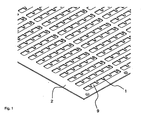
- the Fig. 1 shows a base plate 2 for a first embodiment of a gate valve unit of a filling tube 10 having feeding and sorting device for tablets, capsules, dragees or the like, in particular to thermoforming machines.
- the base plate 2 has a Gearrschreibchen 10 corresponding number of Absperrfingern 1, each associated with the respective Greeg., Camry, Camry, Camry, Camry, Camry, Camry, Camry, or the like, in particular to thermoforming machines.
- the base plate 2 has a Grerschreibchen 10 corresponding number of Absperrfingern 1, each associated with the respective Greerchen 10, and a base plate 2 with through holes 9, wherein the Absperrfinger 1 are integrally formed with the base plate 2.
- the Absperrfinger 1 in the base plate 2 for example, by means of a punching process, a casting method, a spraying method, a laser process or a rapid prototyping method together with the through holes 9 are formed from the base plate 2.
- the tablets or the like are passed via a vibration unit in the feeding and sorting device, where they are sorted by up and down movements in the filling tube 10.
- the tablets or the like are aligned and then separated via the Absperrschieberussi with the Absperrfingern 1 so that they can be fed to the blister packs ordered.
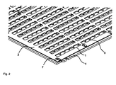
- the Fig. 2 shows a base plate 2 with Absperrfingern 1 according to a second embodiment of the present invention in the locked state with a lower holding plate 4, wherein the matching with the first embodiment of the components with the same Reference numerals are referred to and for the detailed description of which reference is made to the description parts of the first embodiment.
- the base plate 2 is preferably mounted with the through holes 9 in the locked state so that these through holes are substantially congruent with corresponding through holes of the lower plate 4.
- FIG. 3 An enlarged view of the fastening device in the locked state is in the Fig. 3 and in the released state in the Fig. 4 shown.
- a lock 7 which is arranged on the lower plate 4 and having a neck portion and a head portion, in a narrowed portion of the release and locking recess 6 in the base plate 2, so that the head portion of the fastener 7, the base plate 2 on the lower plate 4 secures.
- the lock 7 is in a widened region of the release and locking recess 6 in the base plate 2, so that the base plate 2 can be removed from the lower plate 4 via the head part.
- the Indian Fig. 4 Arrow shown indicates the direction in which the base plate 2 can be moved to backup on the lower plate 4.
- the base plate 2 from the Fig. 4 is moved parallel to the lower plate 4 in the direction of arrow for securing or moved in the opposite direction parallel to the release. In this way, the base plate 2 can be separated and removed without tools from the lower plate 4.
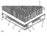
- the Fig. 5 shows a gate valve unit according to a third embodiment of the present invention, wherein the matching with the first and with the second embodiment, components with the same reference numerals are referred to and for the detailed description of which reference is made to the corresponding parts of the description.
- the gate valve unit according to the third embodiment has, instead of a base plate 2, a corresponding lower base plate 2a with lower through holes and a corresponding upper base plate 2b with upper through holes.
- the lower base plate 2a and the upper base plate 2b are arranged in the operating state to each other such that in each case a lower passage opening and a corresponding upper passage opening of a corresponding number of filling tubes 10 are assigned.
- Fig. 6 shows an enlarged view of the guide member 13 in a gate valve unit according to a fourth embodiment, wherein the matching with the first to the third embodiment components are denoted by the same reference numerals and reference is made to the detailed description of the corresponding description parts.
- the guide parts 13 can have different codes both for the connection to an upper cover plate 12 and the connection to a lower cover plate 11 as well as for the guidance of the lower base plate 2a and the upper base plate 2b.
- the lower base plate 2a has a first height H1 and the upper base plate 2b has a second height H2, the first height H1 being different from the second height H2.
- the upper recess 15 on the upper cover plate 12 and the lower recess 14 on the lower cover plate 11 are designed differently. It can, for. B. the lower recess 14 over the entire height of the lower cover plate 11th extend, while the upper recess 15 extends only over a partial height of the upper cover plate 12.
- an upper guide projection 16 adapted to the upper recess 15 is formed on the upper side of the guide member 13, and a guide projection 15 adapted to the lower recess 14 is formed on the underside of the guide member 13.
- the asymmetry of the lower guide projection and the upper guide projection ensures correct installation of the guide parts.
- the Fig. 7 shows that the lower guide is formed as a lower guide groove 18a having a width B1 matching the first height H1, and the upper guide is formed as an upper guide groove 18b having a width B2 corresponding to the second height H2.
- the asymmetry of the lower and the upper guide groove with the asymmetry of the lower and the upper base plate prevents mechanically interchanging the base plates during installation.
- the Fig. 8 shows a Absperrschieberech according to a fifth embodiment in cross-sectional view, in which the upper base plate 2b is adjustably arranged, wherein the matching with the first to the fourth embodiment components are denoted by the same reference numerals and reference is made to the detailed description of the corresponding description parts.
- the end position of the upper base plate 2 b is adjustable in order to ensure optimum blocking of the tablets in the filling tube 10.
- the adjustment is infinitely adjustable. This can be done via a motor.
- the upper base plate 2b is via a pneumatic cylinder 19 moves, which has a continuous piston rod. Via a stop 20, the desired position can be adjusted, wherein the stop is adjustable via the motor, so that no intervention by hand are necessary.
- the technical features of the first to fifth embodiments can be combined with each other. Furthermore, it is possible to replace the base plate 2 with a number of partial base plates, or to replace the upper base plate 2b with a number of upper partial base plates and the lower base plate 2a by a number of lower partial base plates.
Landscapes
- Engineering & Computer Science (AREA)
- Mechanical Engineering (AREA)
- Medical Preparation Storing Or Oral Administration Devices (AREA)
- Sliding Valves (AREA)
- Moulds For Moulding Plastics Or The Like (AREA)
Claims (23)
- Unité de tiroir d'arrêt d'un dispositif d'alimentation et de tri, qui présente des tubes de remplissage (10), pour des comprimés, gélules, dragées ou analogues, en particulier sur des machines de thermoformage, l'unité de tiroir d'arrêt présentant un nombre de doigts d'arrêt (1), correspondant à celui des tubes de remplissage (10), qui sont respectivement associés aux tubes de remplissage (10) concernés, caractérisée en ce que l'unité de tiroir d'arrêt présente une plaque de base (2) avec des ouvertures de passage (9), et que les doigts d'arrêt (1) sont réalisés d'une seule pièce avec la plaque de base (2).
- Unité de tiroir d'arrêt suivant la revendication 1, caractérisée en ce qu'une pluralité de doigts d'arrêt (1) est associée aux ouvertures de passage (9) de la plaque de base (2).
- Unité de tiroir d'arrêt suivant l'une des revendications 1 et 2, caractérisée en ce que la plaque de base (2), avec les doigts d'arrêt (1), est formée d'un matériau rigide, en particulier d'acier, d'aluminium ou de matières plastiques.
- Unité de tiroir d'arrêt suivant la revendication 3, caractérisée en ce que la plaque de base (2), avec les doigts d'arrêt (1), présente un revêtement souple, en particulier un revêtement de silicone.
- Unité de tiroir d'arrêt suivant l'une des revendications 1 et 2, caractérisée en ce que la plaque de base (2), avec les doigts d'arrêt (1), est formée d'un matériau souple, en particulier de silicone.
- Unité de tiroir d'arrêt suivant l'une des revendications précédentes, caractérisée en ce que la plaque de base (2) est formée d'un nombre de plaques de base partielles.
- Unité de tiroir d'arrêt suivant l'une des revendications précédentes, caractérisée par une plaque de retenue inférieure (4), sur laquelle est disposée la plaque de base (2) et sur laquelle est montée au moins un moyen de fixation pour fixer la plaque de base (2) sur la plaque de retenue inférieure (4).
- Unité de tiroir d'arrêt suivant la revendication 7, caractérisée en ce que le moyen de fixation comprend un arrêt de verrou (7), un évidement de dégagement et de blocage (6) étant associé dans la plaque de base (2) à l'arrêt de verrou (7) de telle sorte que la plaque de base (2) est débloquée de la plaque de retenue inférieure (4) ou bloquée sur la plaque de retenue inférieure (4) par un déplacement de la plaque de retenue inférieure (4) par rapport à la plaque de base (2) dans l'évidement de dégagement et de blocage (6).
- Unité de tiroir d'arrêt suivant l'une des revendications 1 à 6, caractérisée par une plaque de retenue supérieure, sur laquelle est disposée la plaque de base (2) et sur laquelle est monté au moins un moyen de fixation pour fixer la plaque de base (2) sur la plaque de retenue supérieure.
- Unité de tiroir d'arrêt suivant la revendication 9, caractérisée en ce que le moyen de fixation comprend un arrêt de verrou, un évidement de dégagement et de blocage étant associé dans la plaque de base (2) à l'arrêt de verrou de telle sorte que la plaque de base (2) est débloquée de la plaque de retenue supérieure ou bloquée sur la plaque de retenue supérieure par un déplacement de la plaque de base (2) par rapport à la plaque de retenue supérieure dans l'évidement de dégagement et de blocage.
- Unité de tiroir d'arrêt suivant l'une des revendications précédentes, caractérisée en ce que l'unité de tiroir d'arrêt présente, au lieu de la plaque de base (2), une plaque de base inférieure (2a) correspondante avec des ouvertures de passage inférieures et une plaque de base supérieure (2b) correspondante avec des ouvertures de passage supérieures, la plaque de base inférieure (2a) et la plaque de base supérieure (2b) étant mutuellement disposées de telle sorte que l'ouverture de passage inférieure et l'ouverture de passage supérieure correspondante sont respectivement associées à un nombre correspondant de tubes de remplissage (10).
- Unité de tiroir d'arrêt suivant la revendication 11, caractérisée en ce que l'unité de tiroir d'arrêt présente au moins un élément de guidage (13) avec une glissière inférieure (18a) pour le guidage de la plaque de base inférieure (2a) et une glissière supérieure (18b) pour le guidage de la plaque de base supérieure (2b), l'élément de guidage (13), ainsi que la plaque de base inférieure (2a) et la plaque de base supérieure (2b), étant disposés entre une plaque de couverture inférieure (11) et une plaque de couverture supérieure (12).
- Unité de tiroir d'arrêt suivant la revendication 12, caractérisée en ce que la plaque de base inférieure (2a), pour la glissière inférieure (18a), et la plaque de base supérieure (2b), pour la glissière supérieure (18b), présentent des codages différents adaptés les uns aux autres.
- Unité de tiroir d'arrêt suivant la revendication 13, caractérisée en ce que la plaque de base inférieure (2a) présente une première hauteur (H1) et la plaque de base supérieure (2b) présente une seconde hauteur (H2), la première hauteur (H1) différant de la seconde hauteur (H2), et que la glissière inférieure est réalisée sous forme d'une rainure de guidage inférieure (18a) de largeur (B1), adaptée à la première hauteur (H1), et la glissière supérieure est réalisée sous forme d'une rainure de guidage supérieure (18b) de largeur (B2), adaptée à la seconde hauteur (H2).
- Unité de tiroir d'arrêt suivant l'une des revendications 13 et 14, caractérisée en ce que l'élément de guidage (13) présente un premier verrou (17) sur le côté tourné vers la plaque de couverture supérieure (12) et un second verrou (16) sur le côté tourné vers la plaque de couverture inférieure (11), de telle sorte que le premier verrou (17) et le second verrou (16) sont différents, une première clef (15) afférente au premier verrou (17) étant réalisée pour un assemblage avec l'élément de guidage (13) sur la plaque de couverture supérieure (12), sur le côté tourné vers l'élément de guidage (13), et une seconde clef (14) afférente au second verrou (16) étant réalisée pour un assemblage avec l'élément de guidage (13) sur la plaque de couverture inférieure (11), sur le côté tourné vers l'élément de guidage (13).
- Unité de tiroir d'arrêt suivant la revendication 15, caractérisée en ce que le premier verrou est réalisé sous forme d'une saillie de guidage supérieure (17) sur le côté supérieur de l'élément de guidage (13), que le second verrou est réalisé sous forme d'une saillie de guidage inférieure (16) sur le côté inférieur de l'élément de guidage (13), que la première clef sur le côté inférieur de la plaque de couverture supérieure est réalisée sous forme d'un évidement de guidage supérieur (15) adapté à la saillie de guidage supérieure (17), et que la seconde clef sur le côté supérieur de la plaque de couverture inférieure (11) est réalisée sous forme d'un évidement de guidage inférieur (14) adapté à la saillie de guidage inférieure (16).
- Unité de tiroir d'arrêt suivant l'une des revendications 11 à 16, caractérisée en ce que la plaque de base supérieure (2b) est montée mobile par rapport à la plaque de base inférieure (2a), une position extrême de la plaque de base supérieure (2b) étant ajustable.
- Unité de tiroir d'arrêt suivant la revendication 17, caractérisée en ce que l'unité de tiroir d'arrêt présente un cylindre pneumatique (19) pour le déplacement de la plaque de base supérieure (2b) et une butée (20) pour limiter le déplacement de la plaque de base supérieure (2b), la butée (20) étant ajustable par l'intermédiaire d'un moteur.
- Procédé de fabrication d'une plaque de base (2) pour une unité de tiroir d'arrêt suivant l'une des revendications 1 à 16, caractérisé en ce que, par l'étape de procédé de la formation des ouvertures de passage (9) dans la plaque de base (2) pour l'unité de tiroir d'arrêt, une mise en forme des doigts d'arrêt (1) hors de la plaque de base (2) est réalisée de telle sorte que les doigts d'arrêt (1) sont formés d'une seule pièce avec la plaque de base (2).
- Procédé suivant la revendication 19, caractérisé en ce que la plaque de base (2), avec les doigts d'arrêt (1), est formée d'un matériau rigide, en particulier d'acier, d'aluminium ou de matières plastiques.
- Procédé suivant la revendication 19, caractérisé en ce que la plaque de base (2), avec les doigts d'arrêt (1), est formée d'un matériau souple, en particulier de silicone.
- Procédé suivant l'une des revendications 19 à 21, caractérisé en ce que le procédé de réalisation des doigts d'arrêt (1) comprend une étape de procédé de fraisage et/ou une étape de procédé de découpage au laser ou par jets d'eau et/ou une étape de procédé d'estampage et/ou une étape de procédé de coulage et/ou une étape de procédé d'injection et/ou une étape de procédé de prototypage rapide.
- Procédé suivant la revendication 22, caractérisé en ce que, après la réalisation des doigts d'arrêt (1), le procédé présente une étape du revêtement de la plaque de base (2), avec les doigts d'arrêt (1), par un matériau souple, en particulier de silicone.
Priority Applications (3)
| Application Number | Priority Date | Filing Date | Title |
|---|---|---|---|
| DE502008002131T DE502008002131D1 (de) | 2008-04-16 | 2008-04-16 | Absperrschiebereinheit einer Zuführ- und Sortiervorrichtung für Verpackungsmaschinen |
| EP08007417A EP2110325B1 (fr) | 2008-04-16 | 2008-04-16 | Unité de vanne d'arrêt d'un dispositif d'alimentation et de tri pour machines d'emballage |
| US12/421,992 US7971727B2 (en) | 2008-04-16 | 2009-04-10 | Blocking slide unit of a feed and sorting device for packaging machines |
Applications Claiming Priority (1)
| Application Number | Priority Date | Filing Date | Title |
|---|---|---|---|
| EP08007417A EP2110325B1 (fr) | 2008-04-16 | 2008-04-16 | Unité de vanne d'arrêt d'un dispositif d'alimentation et de tri pour machines d'emballage |
Publications (2)
| Publication Number | Publication Date |
|---|---|
| EP2110325A1 EP2110325A1 (fr) | 2009-10-21 |
| EP2110325B1 true EP2110325B1 (fr) | 2010-12-29 |
Family
ID=39769258
Family Applications (1)
| Application Number | Title | Priority Date | Filing Date |
|---|---|---|---|
| EP08007417A Active EP2110325B1 (fr) | 2008-04-16 | 2008-04-16 | Unité de vanne d'arrêt d'un dispositif d'alimentation et de tri pour machines d'emballage |
Country Status (3)
| Country | Link |
|---|---|
| US (1) | US7971727B2 (fr) |
| EP (1) | EP2110325B1 (fr) |
| DE (1) | DE502008002131D1 (fr) |
Families Citing this family (3)
| Publication number | Priority date | Publication date | Assignee | Title |
|---|---|---|---|---|
| WO2008035701A1 (fr) * | 2006-09-20 | 2008-03-27 | Yuyama Mfg. Co., Ltd. | Appareil d'emballage de médicaments |
| SI25381A (sl) | 2018-05-03 | 2018-08-31 | BP BLISTER PACK d.o.o. | Postopek sestave in delovanja blokadnega mehanizma dozirnega sistema |
| CN114054376B (zh) * | 2021-12-10 | 2022-08-09 | 广州华银医学检验中心有限公司 | 一种试管样品自动上料分拣装置 |
Family Cites Families (9)
| Publication number | Priority date | Publication date | Assignee | Title |
|---|---|---|---|---|
| US2108906A (en) * | 1937-07-21 | 1938-02-22 | Stephen J Speckhart | Capsule filling machine |
| DE3541672A1 (de) * | 1985-11-26 | 1987-05-27 | Uhlmann Maschf Josef | Vorrichtung an verpackungsmaschinen zum geordneten zufuehren und ablegen zu verpackender kleinteile, wie tabletten, kapseln, dragees oder dergl. |
| US4685271A (en) * | 1986-01-30 | 1987-08-11 | Drug Package, Inc. | Medication packaging and dispensing system |
| US4761932A (en) * | 1987-02-13 | 1988-08-09 | Warner-Lambert Company | Capsule sealing machine |
| US5737902A (en) * | 1996-09-19 | 1998-04-14 | Aylward Enterprises, Inc. | Apparatus and method for packaging pills |
| US7066350B2 (en) * | 2002-08-21 | 2006-06-27 | Aylward Enterprises, Inc. | Feeder tube for filling containers with pills |
| DE502004003043D1 (de) * | 2003-04-08 | 2007-04-12 | Hmh Maschinenhandel | Vorrichtung zum zuführen pharmazeutischer produkte zu blisterpackungen |
| DE102007015647A1 (de) * | 2007-03-31 | 2008-10-02 | Uhlmann Pac-Systeme Gmbh & Co Kg | Zuführung |
| US8943780B1 (en) * | 2007-05-30 | 2015-02-03 | Walgreen Co. | Method and system for verification of product transfer from an intermediate loading cartridge to a multi-container blister pack |
-
2008
- 2008-04-16 DE DE502008002131T patent/DE502008002131D1/de active Active
- 2008-04-16 EP EP08007417A patent/EP2110325B1/fr active Active
-
2009
- 2009-04-10 US US12/421,992 patent/US7971727B2/en active Active
Also Published As
| Publication number | Publication date |
|---|---|
| US7971727B2 (en) | 2011-07-05 |
| DE502008002131D1 (de) | 2011-02-10 |
| EP2110325A1 (fr) | 2009-10-21 |
| US20090263227A1 (en) | 2009-10-22 |
Similar Documents
| Publication | Publication Date | Title |
|---|---|---|
| EP0092686B1 (fr) | Dispositif de changement rapide et/ou serrage de moules pour machines à injection | |
| EP2583916B1 (fr) | Dispositif de guidage pour récipients, notamment pour bouteilles , boîtes, cartons à boissons et/ou cartonnages | |
| EP3180138B1 (fr) | Outil de cintrage et dispositif de préhension servant à manipuler l'outil de cintrage | |
| EP2110324B1 (fr) | Unité de verrouillage d'un dispositif d'alimentation et de tri pour machines d'emballage | |
| EP2110325B1 (fr) | Unité de vanne d'arrêt d'un dispositif d'alimentation et de tri pour machines d'emballage | |
| DE2215506C3 (de) | Verriegelungs- und Entriegelungsmechanismus für Druckgieß- und Spritzgießmaschinen | |
| DE112015005144B4 (de) | Formwerkzeug und Formaustauschverfahren | |
| DE60106739T2 (de) | Spritzgiessmaschine für kunststoffbehälter mit schnellformwechseleinrichtung | |
| DE102007028434B3 (de) | Vollautomatischer Niederhalter für ein Formwerkzeug | |
| EP1858682B1 (fr) | Dispositif pour recevoir un moule de soufflage | |
| EP2489866B1 (fr) | Moteur fusée avec un dispositif de buse deployable | |
| DE2610205A1 (de) | Sicherheitsvorrichtung zum arretieren mehrerer betaetigungshebel | |
| EP3793816B1 (fr) | Entraînement de cale à dispositif de guidage réglable | |
| CH668352A5 (de) | Vorrichtung zum ausstanzen von verschlussgliedern aus einer reissverschlusskette. | |
| EP2292536B1 (fr) | Dispositif de transport destiné au transport de fermetures de récipient | |
| DE102012018242B4 (de) | Vorrichtung zur Herstellung von Siebbelägen | |
| EP2616198B1 (fr) | Dispositif et procédé pour fabriquer des profilés creux au moins partiellement fermés avec un temps de cycle réduit | |
| EP2149501B1 (fr) | Machine d'emballage dotée d'un verrouillage d'outil à 1 point | |
| DE102016202796B4 (de) | Scherenschnittsystem für Drahtverformungsmaschine sowie Drahtverformungsmaschine mit Scherenschnittsystem | |
| DE102017214701A1 (de) | Werkstücktransfersystem und -verfahren | |
| EP1522234B1 (fr) | Procédé pour fabriquer des brosses, en particulier des brosses à dents | |
| DE102013019598B4 (de) | Verfahren und Vorrichtung zur Herstellung von Aussparungen in Haltestangen | |
| DE102017220194A1 (de) | Beutelfüllvorrichtung und Verfahren zum Verarbeiten und Befüllen von Beuteln | |
| DE102007024711B4 (de) | Vorrichtung und Verfahren zum Clinchen von Bauteilen | |
| EP3797893B1 (fr) | Dispositif de découpage fin / découpage normal d' ébauches d'une bande métallique ainsi que de travail en plusieurs étapes des ébauches au moyen d' outils de coupe et de façonnage |
Legal Events
| Date | Code | Title | Description |
|---|---|---|---|
| PUAI | Public reference made under article 153(3) epc to a published international application that has entered the european phase |
Free format text: ORIGINAL CODE: 0009012 |
|
| 17P | Request for examination filed |
Effective date: 20081107 |
|
| AK | Designated contracting states |
Kind code of ref document: A1 Designated state(s): AT BE BG CH CY CZ DE DK EE ES FI FR GB GR HR HU IE IS IT LI LT LU LV MC MT NL NO PL PT RO SE SI SK TR |
|
| AX | Request for extension of the european patent |
Extension state: AL BA MK RS |
|
| AKX | Designation fees paid |
Designated state(s): DE FR GB IE IT SE |
|
| GRAP | Despatch of communication of intention to grant a patent |
Free format text: ORIGINAL CODE: EPIDOSNIGR1 |
|
| GRAS | Grant fee paid |
Free format text: ORIGINAL CODE: EPIDOSNIGR3 |
|
| GRAA | (expected) grant |
Free format text: ORIGINAL CODE: 0009210 |
|
| AK | Designated contracting states |
Kind code of ref document: B1 Designated state(s): DE FR GB IE IT SE |
|
| REG | Reference to a national code |
Ref country code: GB Ref legal event code: FG4D Free format text: NOT ENGLISH |
|
| REG | Reference to a national code |
Ref country code: IE Ref legal event code: FG4D Free format text: LANGUAGE OF EP DOCUMENT: GERMAN |
|
| REF | Corresponds to: |
Ref document number: 502008002131 Country of ref document: DE Date of ref document: 20110210 Kind code of ref document: P |
|
| REG | Reference to a national code |
Ref country code: DE Ref legal event code: R096 Ref document number: 502008002131 Country of ref document: DE Effective date: 20110210 |
|
| PG25 | Lapsed in a contracting state [announced via postgrant information from national office to epo] |
Ref country code: SE Free format text: LAPSE BECAUSE OF FAILURE TO SUBMIT A TRANSLATION OF THE DESCRIPTION OR TO PAY THE FEE WITHIN THE PRESCRIBED TIME-LIMIT Effective date: 20101229 |
|
| PLBE | No opposition filed within time limit |
Free format text: ORIGINAL CODE: 0009261 |
|
| STAA | Information on the status of an ep patent application or granted ep patent |
Free format text: STATUS: NO OPPOSITION FILED WITHIN TIME LIMIT |
|
| 26N | No opposition filed |
Effective date: 20110930 |
|
| REG | Reference to a national code |
Ref country code: FR Ref legal event code: ST Effective date: 20111230 |
|
| REG | Reference to a national code |
Ref country code: DE Ref legal event code: R097 Ref document number: 502008002131 Country of ref document: DE Effective date: 20110930 |
|
| PG25 | Lapsed in a contracting state [announced via postgrant information from national office to epo] |
Ref country code: FR Free format text: LAPSE BECAUSE OF NON-PAYMENT OF DUE FEES Effective date: 20110502 |
|
| REG | Reference to a national code |
Ref country code: DE Ref legal event code: R082 Ref document number: 502008002131 Country of ref document: DE Representative=s name: KROHER . STROBEL RECHTS- UND PATENTANWAELTE PA, DE Ref country code: DE Ref legal event code: R081 Ref document number: 502008002131 Country of ref document: DE Owner name: UHLMANN PAC-SYSTEME GMBH & CO. KG, DE Free format text: FORMER OWNER: UHLMANN PAC-SYSTEME GMBH & CO KG, 88471 LAUPHEIM, DE Ref country code: DE Ref legal event code: R082 Ref document number: 502008002131 Country of ref document: DE Representative=s name: KROHER STROBEL RECHTS- UND PATENTANWAELTE PART, DE |
|
| REG | Reference to a national code |
Ref country code: DE Ref legal event code: R082 Ref document number: 502008002131 Country of ref document: DE Representative=s name: KROHER STROBEL RECHTS- UND PATENTANWAELTE PART, DE |
|
| PGFP | Annual fee paid to national office [announced via postgrant information from national office to epo] |
Ref country code: IT Payment date: 20230428 Year of fee payment: 16 Ref country code: IE Payment date: 20230420 Year of fee payment: 16 Ref country code: DE Payment date: 20230427 Year of fee payment: 16 |
|
| PGFP | Annual fee paid to national office [announced via postgrant information from national office to epo] |
Ref country code: GB Payment date: 20230420 Year of fee payment: 16 |