EP2109490B1 - Verwendung von so2 aus rauchgas für säurewäsche von ammoniak - Google Patents
Verwendung von so2 aus rauchgas für säurewäsche von ammoniak Download PDFInfo
- Publication number
- EP2109490B1 EP2109490B1 EP08713849A EP08713849A EP2109490B1 EP 2109490 B1 EP2109490 B1 EP 2109490B1 EP 08713849 A EP08713849 A EP 08713849A EP 08713849 A EP08713849 A EP 08713849A EP 2109490 B1 EP2109490 B1 EP 2109490B1
- Authority
- EP
- European Patent Office
- Prior art keywords
- process gas
- gas
- cooling
- ammonia
- liquid
- Prior art date
- Legal status (The legal status is an assumption and is not a legal conclusion. Google has not performed a legal analysis and makes no representation as to the accuracy of the status listed.)
- Active
Links
Images

Classifications
-
- B—PERFORMING OPERATIONS; TRANSPORTING
- B01—PHYSICAL OR CHEMICAL PROCESSES OR APPARATUS IN GENERAL
- B01D—SEPARATION
- B01D53/00—Separation of gases or vapours; Recovering vapours of volatile solvents from gases; Chemical or biological purification of waste gases, e.g. engine exhaust gases, smoke, fumes, flue gases, aerosols
- B01D53/14—Separation of gases or vapours; Recovering vapours of volatile solvents from gases; Chemical or biological purification of waste gases, e.g. engine exhaust gases, smoke, fumes, flue gases, aerosols by absorption
- B01D53/1456—Removing acid components
-
- B—PERFORMING OPERATIONS; TRANSPORTING
- B01—PHYSICAL OR CHEMICAL PROCESSES OR APPARATUS IN GENERAL
- B01D—SEPARATION
- B01D53/00—Separation of gases or vapours; Recovering vapours of volatile solvents from gases; Chemical or biological purification of waste gases, e.g. engine exhaust gases, smoke, fumes, flue gases, aerosols
- B01D53/34—Chemical or biological purification of waste gases
- B01D53/46—Removing components of defined structure
- B01D53/48—Sulfur compounds
- B01D53/50—Sulfur oxides
- B01D53/501—Sulfur oxides by treating the gases with a solution or a suspension of an alkali or earth-alkali or ammonium compound
-
- B—PERFORMING OPERATIONS; TRANSPORTING
- B01—PHYSICAL OR CHEMICAL PROCESSES OR APPARATUS IN GENERAL
- B01D—SEPARATION
- B01D53/00—Separation of gases or vapours; Recovering vapours of volatile solvents from gases; Chemical or biological purification of waste gases, e.g. engine exhaust gases, smoke, fumes, flue gases, aerosols
- B01D53/34—Chemical or biological purification of waste gases
- B01D53/46—Removing components of defined structure
- B01D53/62—Carbon oxides
-
- B—PERFORMING OPERATIONS; TRANSPORTING
- B01—PHYSICAL OR CHEMICAL PROCESSES OR APPARATUS IN GENERAL
- B01D—SEPARATION
- B01D53/00—Separation of gases or vapours; Recovering vapours of volatile solvents from gases; Chemical or biological purification of waste gases, e.g. engine exhaust gases, smoke, fumes, flue gases, aerosols
- B01D53/34—Chemical or biological purification of waste gases
- B01D53/74—General processes for purification of waste gases; Apparatus or devices specially adapted therefor
- B01D53/75—Multi-step processes
-
- F—MECHANICAL ENGINEERING; LIGHTING; HEATING; WEAPONS; BLASTING
- F23—COMBUSTION APPARATUS; COMBUSTION PROCESSES
- F23J—REMOVAL OR TREATMENT OF COMBUSTION PRODUCTS OR COMBUSTION RESIDUES; FLUES
- F23J15/00—Arrangements of devices for treating smoke or fumes
- F23J15/006—Layout of treatment plant
-
- F—MECHANICAL ENGINEERING; LIGHTING; HEATING; WEAPONS; BLASTING
- F23—COMBUSTION APPARATUS; COMBUSTION PROCESSES
- F23J—REMOVAL OR TREATMENT OF COMBUSTION PRODUCTS OR COMBUSTION RESIDUES; FLUES
- F23J15/00—Arrangements of devices for treating smoke or fumes
- F23J15/02—Arrangements of devices for treating smoke or fumes of purifiers, e.g. for removing noxious material
- F23J15/04—Arrangements of devices for treating smoke or fumes of purifiers, e.g. for removing noxious material using washing fluids
-
- F—MECHANICAL ENGINEERING; LIGHTING; HEATING; WEAPONS; BLASTING
- F23—COMBUSTION APPARATUS; COMBUSTION PROCESSES
- F23J—REMOVAL OR TREATMENT OF COMBUSTION PRODUCTS OR COMBUSTION RESIDUES; FLUES
- F23J15/00—Arrangements of devices for treating smoke or fumes
- F23J15/06—Arrangements of devices for treating smoke or fumes of coolers
-
- B—PERFORMING OPERATIONS; TRANSPORTING
- B01—PHYSICAL OR CHEMICAL PROCESSES OR APPARATUS IN GENERAL
- B01D—SEPARATION
- B01D2251/00—Reactants
- B01D2251/60—Inorganic bases or salts
- B01D2251/604—Hydroxides
-
- B—PERFORMING OPERATIONS; TRANSPORTING
- B01—PHYSICAL OR CHEMICAL PROCESSES OR APPARATUS IN GENERAL
- B01D—SEPARATION
- B01D2252/00—Absorbents, i.e. solvents and liquid materials for gas absorption
- B01D2252/10—Inorganic absorbents
- B01D2252/102—Ammonia
-
- B—PERFORMING OPERATIONS; TRANSPORTING
- B01—PHYSICAL OR CHEMICAL PROCESSES OR APPARATUS IN GENERAL
- B01D—SEPARATION
- B01D2257/00—Components to be removed
- B01D2257/30—Sulfur compounds
- B01D2257/302—Sulfur oxides
-
- B—PERFORMING OPERATIONS; TRANSPORTING
- B01—PHYSICAL OR CHEMICAL PROCESSES OR APPARATUS IN GENERAL
- B01D—SEPARATION
- B01D2257/00—Components to be removed
- B01D2257/50—Carbon oxides
- B01D2257/504—Carbon dioxide
-
- F—MECHANICAL ENGINEERING; LIGHTING; HEATING; WEAPONS; BLASTING
- F23—COMBUSTION APPARATUS; COMBUSTION PROCESSES
- F23J—REMOVAL OR TREATMENT OF COMBUSTION PRODUCTS OR COMBUSTION RESIDUES; FLUES
- F23J2215/00—Preventing emissions
- F23J2215/20—Sulfur; Compounds thereof
-
- F—MECHANICAL ENGINEERING; LIGHTING; HEATING; WEAPONS; BLASTING
- F23—COMBUSTION APPARATUS; COMBUSTION PROCESSES
- F23J—REMOVAL OR TREATMENT OF COMBUSTION PRODUCTS OR COMBUSTION RESIDUES; FLUES
- F23J2215/00—Preventing emissions
- F23J2215/50—Carbon dioxide
-
- F—MECHANICAL ENGINEERING; LIGHTING; HEATING; WEAPONS; BLASTING
- F23—COMBUSTION APPARATUS; COMBUSTION PROCESSES
- F23J—REMOVAL OR TREATMENT OF COMBUSTION PRODUCTS OR COMBUSTION RESIDUES; FLUES
- F23J2219/00—Treatment devices
- F23J2219/40—Sorption with wet devices, e.g. scrubbers
-
- Y—GENERAL TAGGING OF NEW TECHNOLOGICAL DEVELOPMENTS; GENERAL TAGGING OF CROSS-SECTIONAL TECHNOLOGIES SPANNING OVER SEVERAL SECTIONS OF THE IPC; TECHNICAL SUBJECTS COVERED BY FORMER USPC CROSS-REFERENCE ART COLLECTIONS [XRACs] AND DIGESTS
- Y02—TECHNOLOGIES OR APPLICATIONS FOR MITIGATION OR ADAPTATION AGAINST CLIMATE CHANGE
- Y02A—TECHNOLOGIES FOR ADAPTATION TO CLIMATE CHANGE
- Y02A50/00—TECHNOLOGIES FOR ADAPTATION TO CLIMATE CHANGE in human health protection, e.g. against extreme weather
- Y02A50/20—Air quality improvement or preservation, e.g. vehicle emission control or emission reduction by using catalytic converters
-
- Y—GENERAL TAGGING OF NEW TECHNOLOGICAL DEVELOPMENTS; GENERAL TAGGING OF CROSS-SECTIONAL TECHNOLOGIES SPANNING OVER SEVERAL SECTIONS OF THE IPC; TECHNICAL SUBJECTS COVERED BY FORMER USPC CROSS-REFERENCE ART COLLECTIONS [XRACs] AND DIGESTS
- Y02—TECHNOLOGIES OR APPLICATIONS FOR MITIGATION OR ADAPTATION AGAINST CLIMATE CHANGE
- Y02C—CAPTURE, STORAGE, SEQUESTRATION OR DISPOSAL OF GREENHOUSE GASES [GHG]
- Y02C20/00—Capture or disposal of greenhouse gases
- Y02C20/40—Capture or disposal of greenhouse gases of CO2
-
- Y—GENERAL TAGGING OF NEW TECHNOLOGICAL DEVELOPMENTS; GENERAL TAGGING OF CROSS-SECTIONAL TECHNOLOGIES SPANNING OVER SEVERAL SECTIONS OF THE IPC; TECHNICAL SUBJECTS COVERED BY FORMER USPC CROSS-REFERENCE ART COLLECTIONS [XRACs] AND DIGESTS
- Y02—TECHNOLOGIES OR APPLICATIONS FOR MITIGATION OR ADAPTATION AGAINST CLIMATE CHANGE
- Y02E—REDUCTION OF GREENHOUSE GAS [GHG] EMISSIONS, RELATED TO ENERGY GENERATION, TRANSMISSION OR DISTRIBUTION
- Y02E20/00—Combustion technologies with mitigation potential
- Y02E20/30—Technologies for a more efficient combustion or heat usage
-
- Y—GENERAL TAGGING OF NEW TECHNOLOGICAL DEVELOPMENTS; GENERAL TAGGING OF CROSS-SECTIONAL TECHNOLOGIES SPANNING OVER SEVERAL SECTIONS OF THE IPC; TECHNICAL SUBJECTS COVERED BY FORMER USPC CROSS-REFERENCE ART COLLECTIONS [XRACs] AND DIGESTS
- Y02—TECHNOLOGIES OR APPLICATIONS FOR MITIGATION OR ADAPTATION AGAINST CLIMATE CHANGE
- Y02E—REDUCTION OF GREENHOUSE GAS [GHG] EMISSIONS, RELATED TO ENERGY GENERATION, TRANSMISSION OR DISTRIBUTION
- Y02E20/00—Combustion technologies with mitigation potential
- Y02E20/32—Direct CO2 mitigation
Definitions
- the present invention relates to a method of cleaning a process gas containing carbon dioxide and sulphur dioxide, said method including removing, at least partly, sulphur dioxide from the process gas by means of, in a first step, cooling the process gas, and, in a second step, bringing the cooled process gas into contact with an ammoniated solution or slurry absorbing at least a part of the carbon dioxide.
- the present invention also relates to a gas cleaning system which is operative for cleaning a process gas containing carbon dioxide and sulphur dioxide, said gas cleaning system comprising a combined cooling and cleaning system, which is operative for cooling the process gas, and a carbon dioxide removal system comprising a CO 2 -absorber which is operative for removing, at least partly, carbon dioxide from the process gas by bringing the cooled process gas into contact with an ammoniated solution or slurry absorbing at least a part of the carbon dioxide.
- a hot process gas is generated, such as a hot process gas, often referred to as a flue gas, containing, among other components, carbon dioxide, CO 2 .
- a hot process gas often referred to as a flue gas
- CO 2 carbon dioxide
- WO 2006/022885 describes one such process for absorbing carbon dioxide from a flue gas.
- the flue gas is first treated by means of conventional air pollution control processes, like particulate collectors, NOx and SO2 control, acid mist capturing device and more.
- the flue gas then, after the conventional air pollution control processes, has a temperature of about 40-70 °C.
- the flue gas is then cooled down to, preferably, 0-20°C by means of direct contact cooling, in which the flue gas is cooled by means of cold water.
- the flue gas is then brought to a CO 2 absorber, in which the flue gas is brought into contact with a low temperature ammoniated slurry or solution, which is carbon dioxide lean.
- the carbon dioxide is absorbed in the ammoniated slurry or solution, and a clean flue gas, containing very small amounts of pollutants and carbon dioxide, leaves the CO 2 absorber.
- the carbon dioxide rich ammoniated slurry or solution is regenerated in a regenerator, in which the carbon dioxide is stripped, at a temperature of about 50-200°C and under high pressure, to form a concentrated carbon dioxide rich stream.
- a problem of the process described in WO 2006/022885 is that the clean flue gas released from the CO 2 absorber will contain a substantial amount of ammonia.
- the ammonia concentration of the clean flue gas can be kept as low as possible by means of low flue gas temperature in the CO 2 absorber, low NH 3 /CO 2 ratio in the slurry of the CO 2 absorber, and a cold water wash of the flue gas before releasing it to the atmosphere.
- Such water wash can reduce the ammonia concentration in the clean flue gas to the range of about 100-1000 ppm, and preferably to the range of about 100-400 ppm, which is still too high for discharging such a flue gas to the atmosphere.
- EP 1733 782 A1 describe a method and apparatus for removing carbon dioxide from sulphur dioxide containing flue gas. In a first washing stage the sulphur dioxide is removed, in a second washing stage the carbon dioxide is removed.
- An object of the present invention is to provide an efficient and environmentally acceptable method of removing carbon dioxide from a process gas.
- An advantage of this method is that the carbon dioxide is removed from the process gas in an efficient manner, without causing emissions of other substances, such as ammonia, to the environment.
- the sulphur dioxide of the process gas being cooled in the first step is absorbed and is utilized as a substance making it possible to effectively remove, in the third step, the ammonia from the process gas containing ammonia.
- One acid component of the process gas, the sulphur dioxide is thus utilized for absorbing one alkaline component, i.e., the ammonia, that could be said to form a contaminant added to the process gas in the second step, such that these two components do in fact neutralize each other.
- the process gas is very effectively cleaned, from both carbon dioxide, sulphur dioxide, and ammonia, such that the process gas may subsequently be released to the atmosphere without negative effects on the environment, or on human health.
- the cooling liquid containing sulphate is, in the third step, cooled by means of the process gas containing ammonia, the thereby cooled cooling liquid being utilized in the first step for the cooling of the process gas.
- the cooling, in the third step, of the cooling liquid containing sulphate makes it more suitable for being re-used as a cooling medium in said first step, thereby closing, to a large extent, the liquid balance of the process.
- the process gas containing ammonia will be heated by the cooling liquid containing sulphate, making the process gas more suitable for being released to the atmosphere.
- said first step comprises cooling the process gas and absorbing sulphur dioxide in the cooling liquid by means of a first gas-liquid contacting device
- said third step comprises removing ammonia from the process gas containing ammonia by means of the cooling liquid containing sulphate by means of a second gas-liquid contacting device.
- the gas-liquid contacting devices improves the direct contact between gas and liquid, and increases the exchange of heat between the liquid and the gas, and the absorption of sulphur dioxide and ammonia in the cooling liquid.
- the ammonia of the process gas containing ammonia and the sulphate of the cooling liquid containing sulphate at least partly react to form ammonium sulphate in aqueous solution.
- Ammonium sulphate is rather harmless to human health, and is also rather inert, such that re-evaporation of sulphur dioxide from the cooling liquid is not likely.
- the ammonium sulphate may, after proper treatment, be used as a fertilizer.
- the cooling liquid utilized for cooling the process gas in the first step is treated in a heat exchanger for recovering energy.
- the energy may be used in another part of the process, for example in a regenerator in which the CO 2 -rich slurry or solution from the CO 2 -absorber is regenerated.
- the pH-value of the cooling liquid containing sulphate, such cooling liquid being obtained in the first step is controlled to be in the range of pH about 4-6. This pH-range has been found to be suitable to obtain a cleaned process gas containing a low concentration of pollutants, including ammonia.
- the process gas prior to being cooled in said first step, is treated in a sulphur dioxide removal device to remove a portion of its sulphur dioxide content, the efficiency of the sulphur dioxide removal device being controlled to obtain a process gas, to be treated in said first step, which comprises an amount of sulphur dioxide which has a relation to the amount of ammonia of the process gas containing ammonia, to be treated in said third step, of about 1:2 on a molar basis.
- An advantage of this embodiment is that the amount of sulphur dioxide removed in the first step can be controlled to correspond to the amount needed in the cooling liquid containing sulphate for absorbing the ammonia in the third step.
- the second step comprises partly removing ammonia from the process gas containing ammonia by means of a water wash device, the efficiency of the water wash device being controlled to obtain a process gas containing ammonia, to be treated in said third step, which comprises an amount of ammonia which has a relation to the amount of sulphur dioxide of the process gas, to be treated in said first step, of about 2:1 on a molar basis.
- An advantage of this embodiment is that the amount of ammonia to be removed in the third step can be controlled to correspond to the amount of sulphur dioxide absorbed in the cooling liquid, and forming the cooling liquid containing sulphate, in the first step.
- sulphuric acid is added to the cooling liquid to control its pH-value.
- An advantage of this embodiment is that sulphuric acid provides for increasing, quickly and at low cost, the ammonia removal capability of the cooling liquid containing sulphate, e.g., in situations when the amount of sulphur dioxide removed in the first step is not sufficient in view of the amount of ammonia to be removed in the third step.
- a further object of the present invention is to provide a gas cleaning system which is operative for an efficient and environmentally acceptable removal of carbon dioxide from a process gas.
- An advantage of this gas cleaning system is that it is efficient for removing sulphur dioxide, and for utilizing the removed sulphur dioxide, in the form of sulphate contained in the cooling liquid, for removing ammonia from the process gas that has been treated in the carbon dioxide removal system, and which contains, as a consequence of such treatment, ammonia.
- the two gas-liquid contacting devices will also, in addition to being absorbers for sulphur dioxide and ammonia, respectively, function as heat transfer devices being operative for cooling the process gas, prior to being treated in the carbon dioxide removal system, and heating the process gas, prior to being released to the atmosphere, respectively.
- the second gas-liquid contacting device is operative for cooling the cooling liquid containing sulphate by means of the process gas containing ammonia, a liquid transport device being operative for recirculating at least a part of the cooled cooling liquid from the second gas-liquid contacting device to the first gas-liquid contacting device.
- the combined cooling and cleaning system comprises a control device which is operative for controlling the pH-value of the cooling liquid containing sulphate. Controlling the pH-value of the cooling liquid containing sulphate improves the control of the removal of ammonia from the process gas containing ammonia in the second gas-liquid contacting device.
- ppm refers to parts per million on a volume basis.
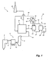
- Fig. 1 is a schematic side view and illustrates a power plant 1, as seen from the side thereof.
- the power plant 1 comprises a boiler 2.
- a hot process gas often referred to as a flue gas
- the flue gas which contains polluting substances, including dust particles, sulphur dioxide, SO 2 , sulphur trioxide, SO 3 and carbon dioxide, CO 2 , leaves the boiler 2 via a gas duct 4.
- the gas duct 4 is operative for forwarding the flue gas to a conventional air pollution control system 6.
- the conventional air pollution control system 6 includes a dust collector 8, in the form of, e.g., an electrostatic precipitator, an example of which is described in US 4,502,872 . Furthermore, the conventional air pollution control system 6 comprises a duct 10 which is operative for forwarding the flue gas from the dust collector 8 to a sulphur dioxide removal device 12, sometimes referred to as a Flue Gas Desulfurization system (FGD), in the form of a wet scrubber.
- FGD Flue Gas Desulfurization system
- An example of a wet scrubber can be found in EP 0 162 536 A1 . In such a wet scrubber the sulphur dioxide is removed from the flue gas by means of contacting the flue gas with a lime stone slurry.
- Flue gas in coal or oil fired power plants contains SO 2 , which is formed when sulphur-laden coal or oil is combusted. In a typical power plant about 90-98% of the SO 2 is captured in the sulphur dioxide removal device 12, and the flue gas leaving such a sulphur dioxide removal device 12 typically contains about 20-200 ppm of SO 2 .
- the sulphur dioxide removal device 12 could also be a so-called dry system, an example of which is illustrated in WO 2004/026443 A1 , in which the flue gas is contacted with a moistened absorbent material.
- the conventional air pollution control system 6 could comprise further devices, such as a selective catalytic reduction reactor, e.g., of the type described in US 5,555,849 , for removing nitrogen oxides from the flue gas, such further devices not being illustrated in Fig. 1 for reasons of clarity of illustration.
- the flue gas which comprises very small amounts of most pollutants, but still most of the original concentration of carbon dioxide, leaves the conventional air pollution control system 6 via a duct 14.
- the duct 14 is operative for forwarding the flue gas to a combined cooling and cleaning system 16, which will be described in more detail hereinafter.
- the flue gas forwarded in the duct 14 typically has a temperature of 49-60°C (120-140°F), is at ambient pressure, and is saturated with water.
- the flue gas leaves the combined cooling and cleaning system 16 via a duct 18.
- the flue gas in the duct 18 has a temperature of 0-20°C, preferably 0-10°C.
- the duct 18 is operative for forwarding the flue gas to a carbon dioxide removal system 20.
- the carbon dioxide removal system 20 is rather similar to the carbon dioxide removal system described with reference to Fig. 1 of WO 2006/022885 .
- the type of carbon dioxide removal system described in WO 2006/022885 is sometimes referred to as the Chilled Ammonia Process, CAP.
- a flue gas temperature of 0-20°C, preferably 0-10°C, is suitable for the carbon dioxide removal system 20.
- the carbon dioxide removal system 20 comprises, with reference to Fig. 1 of the present application, a CO 2 -absorber 22 in which the flue gas is brought into contact with an ammoniated slurry or solution in a similar manner as described in WO 2006/022885 .
- a pipe 24 is operative for forwarding, by means of a high pressure pump, not illustrated in Fig. 1 for reasons of clarity, a CO 2 -enriched slurry or solution from the CO 2 -absorber 22 to a regenerator 26. Heat is provided to the regenerator 26 by heating stream 28 in heater 30. The high pressure and high temperature in the regenerator 26 causes the release of high-pressure gaseous CO 2 , stream 32.
- a pipe 34 is operative for returning CO 2 -lean ammoniated solution or slurry, that has been cooled in a cooler, not illustrated in Fig. 1 , from the regenerator 26 to the CO 2 -absorber 22.
- a duct 36 is operative for forwarding flue gas, having a low concentration of carbon dioxide, from the CO 2 -absorber 22 to a water wash vessel 38, which is optional and which is operative for removing ammonia, NH 3 , from the flue gas that has been treated in the CO 2 -absorber 22.
- the water wash vessel 38 could have a similar design as the water wash vessel described as reference 356 in WO 2006/022885 with reference to Fig. 3 of that application.
- a stream 40 of cold water or cold and slightly acidic solution is cooled in a heat exchanger 42 and is supplied to the water wash vessel 38.
- a duct 44 is operative for forwarding flue gas, that has been cleaned in the water wash vessel 38, to the combined cooling and cleaning system 16 for further cleaning, as will be described in more detail hereinafter.
- a duct 46 is operative for forwarding flue gas, that has been cleaned further in the combined cooling and cleaning system 16, to a stack 48 which releases the cleaned flue gas to the atmosphere.
- Fig. 2 illustrates the combined cooling and cleaning system 16 in more detail.
- the flue gas from the sulphur dioxide removal device 12 enters the combined cooling and cleaning system 16 via the duct 14, which has been described hereinbefore with reference to Fig. 1 .
- the flue gas first reaches a first gas-liquid contacting device in the form of a first direct contact cooler 50 having the shape of a tower.
- the first direct contact cooler 50 is operative for efficient cooling of the flue gas by contacting it directly with a cooling liquid in the form of cooling water having a temperature of, for example, 20.5°C [69°F], which is supplied via a pipe 52.
- a set of nozzles 54 is operative for distributing the cooling water over a contacting device 56, which could have the form of a structured packing, or another suitable type of gas-liquid contacting filling.
- the flue gas having a temperature of, for example, 57°C [135°F], enters the first direct contact cooler 50 via a gas inlet 58 and is forwarded upwards, through the contacting device 56.
- the flue gas leaves the first direct contact cooler 50 at a temperature of 21 °C [70°F] via a gas outlet 60.
- the cooling water and the flue gas are contacted with each other in the contacting device 56 under exchange of heat.
- the warm cooling water is collected in a tank 62 located at the bottom of the first direct contact cooler 50.
- the cooling water collected in the tank 62 has a temperature of, for example, 55.5°C [132°F].
- a mist eliminator 64 is located for the purpose of collecting water droplets entrained by the flue gas.
- the first direct contact cooler 50 is a counter-current gas-liquid contacting vessel designed to achieve low temperature difference on both ends of the vessel.
- the temperature difference at the top of the first direct contact cooler 50 i.e., between the cold cooling water supplied via the pipe 52 and the flue gas about to leave the first direct contact cooler 50 via the gas outlet 60, is designed to be less than 3°C [5°F], and preferably about 0.6°C [1 °F].
- the temperature difference at the bottom of the first direct contact cooler 50 i.e., between the warm cooling water collected in the tank 62 for further transport and the flue gas about to enter the first direct contact cooler 50 via the gas inlet 58, is designed to be less than 3°C [5°F], and preferably about 0.6°C [1 °F]. Lowering the temperature difference results in maximum cooling of the flue gas and maximum heating of the cooling water. Lowering the temperature of the flue gas, that is about to leave the first direct contact cooler 50 via the gas outlet 60, saves cooling power downstream in the process.
- a duct 66 is operative for forwarding the flue gas from the gas outlet 60 to a first indirect cooler 68 and a second indirect cooler 70.
- a pipe 72 supplies cooling liquid to the first indirect cooler 68 and to a chiller 74.
- the chiller 74 cools, further, the cooling liquid before supplying it to the second indirect cooler 70.
- a pipe 76 returns the spent cooling liquid from the first and second indirect coolers 68, 70.
- the cooling liquid circulating in the pipes 72, 76 could be cooled in a cooling tower, not illustrated in Fig. 2
- the duct 18, which has been described hereinbefore with reference to Fig. 1 is operative for forwarding the flue gas, having the desired temperature of 0-20°C, preferably 0-10°C, from the second indirect cooler 70 to the carbon dioxide removal system 20, which has also been described hereinbefore with reference to Fig. 1 .
- a pump 78 is operative for forwarding, via a pipe 80, the warm cooling water collected in the tank 62 of the first direct contact cooler 50 to a heat exchanger 82.
- the warm cooling water is cooled from about 55.5°C [132°F] to, for example, about 35°C [95°F].
- the warm cooling water is used as a source of heat to be utilized elsewhere in the process.
- the heat which otherwise would be wasted and rejected in a cooling tower 84, is transferred to the heat exchanger 82 and is used for regeneration. Higher temperature of the warm cooling water forwarded in the pipe 80 improves waste energy utilization and thus improves the overall energy efficiency of the power plant 1.
- a pipe 86 is operative for forwarding the cooling water from the heat exchanger 82 to the cooling tower 84.
- Heat not rejected for useful purposes in the heat exchanger 82 is rejected as waste energy in the cooling tower 84.
- Ambient air is supplied via an inlet duct 88 to the cooling tower 84 and cools the warm cooling water in accordance with the well-known principles of cooling towers.
- the heated ambient air leaves the cooling tower 84 via an outlet duct 90.
- the cooled cooling liquid having a temperature of about 25°C [77°F], leaves the cooling tower 84 via a pipe 92.
- the combined cooling and cleaning system 16 further comprises a second gas-liquid contacting device in the form of a second direct contact cooler 94 having the shape of a tower.
- the second direct contact cooler 94 is operative for efficient cooling of the cooling liquid, which is supplied to the second direct contact cooler 94 by means of the pipe 92, by contacting the cooling liquid directly with the cool flue gas that has passed through the entire carbon dioxide removal system 20, described with reference to Fig. 1 , and which is forwarded to a gas inlet 96 of the second direct contact cooler 94 by means of the duct 44, which has been described hereinbefore with reference to Fig. 1 .
- the flue gas from which most of the carbon dioxide has been removed in the carbon dioxide removal system 20, has, when it enters the gas inlet 96, a temperature of, for example, 5°C [41 °F].
- a set of nozzles 98 is operative for distributing the cooling water supplied by the pipe 92 over a contacting device 100, which could be similar to the contacting device 56.
- the flue gas entering via the gas inlet 96 is forwarded upwards, through the contacting device 100, and leaves the second direct contact cooler 94 at a temperature of 24.5°C [76°F] via a gas outlet 102.
- the gas outlet 102 is connected to the duct 46, which has been described hereinbefore with reference to Fig. 1 and which is operative for forwarding the cleaned flue gas from the combined cooling and cleaning system 16 to the stack 48.
- the cooling water and the flue gas are contacted with each other in the contacting device 100 under exchange of heat.
- the cooled cooling water is collected in a tank 104 located at the bottom of the second direct contact cooler 94.
- the cooling water collected in the tank 104 has a temperature of, for example, 20.5°C [69°F], as mentioned hereinbefore with reference to the pipe 52.
- a pump 106 is operative for forwarding the cold cooling water from the tank 104 to the first direct contact cooler 50 via the pipe 52.
- a mist eliminator 108 is located for the purpose of collecting water droplets entrained by the flue gas.
- the second direct contact cooler 94 is a counter-current gas-liquid contacting vessel designed to achieve low temperature difference on both ends of the vessel.
- the temperature difference at the top of the second direct contact cooler 94 i.e., between the cooling water supplied via the pipe 92 and the flue gas about to leave the second direct contact cooler 94 via the gas outlet 102, is designed to be less than 3°C [5°F], and preferably about 0.6°C [1°F]. Higher temperature in the clean flue gas improves its buoyancy and reduces the reheat load, i.e., the heat input required to heat the clean flue gas to a certain temperature, if required.
- the first direct contact cooler 50 cools the flue gas coming from the conventional air pollution control system 6, described hereinbefore with reference to Fig. 1 , by means of cooling water, a cooling water which is cooled in a heat exchanger 82, and a cooling tower 84.
- the cooling water is further cooled in the second direct contact cooler 94 by means of being contacted with the cool flue gas coming from the carbon dioxide removal system 20, described hereinbefore with reference to Fig. 1 .
- the flue gas forwarded in the duct 14 contains residual sulphur dioxide, SO 2 , that was not captured in the sulphur dioxide removal device 12, described hereinbefore with reference to Fig. 1 .
- the sulphuric acid, H 2 SO 4 thus formed will dissociate in the aqueous solution, and will decrease the pH of the cooling water.
- the cooling water leaving the first direct contact cooler 50 via the pipe 80 has a rather low pH, thanks to the absorption of SO2, and is utilized, as will be described hereinafter, for removing ammonia from the flue gas, which is forwarded from the carbon dioxide removal system 20 via the duct 44, in the second direct contact cooler 94.
- the flue gas enters the second direct contact cooler 94 via the gas inlet 96.
- the flue gas entering the second direct contact cooler 94 contains about 100-1000 ppm of ammonia, NH 3 , and more typically 200-400 ppm of ammonia, depending on the design and operating conditions of the ammonia wash system, i.e., the water wash vessel 38 described hereinbefore with reference to Fig. 1 .
- the ammonia concentration of the flue gas discharged to the atmosphere should be lower than about 10 ppm, and preferably less than about 1 ppm. This can be achieved in the second direct contact cooler 94.
- the cooling water being forwarded in the pipe 92 from the cooling tower 84 to the second direct contact cooler 94 has a pH of about 4-6, since the cooling water has absorbed sulphur dioxide, SO 2 , in the first direct contact cooler 50.
- the acid source is the SO 2 in the flue gas.
- the slightly acidic cooling water is used for capturing ammonia from the flue gas entering the second direct contact cooler 94 via the gas inlet 96 and for reheating this flue gas before releasing it to the atmosphere.
- the second direct contact cooler 94 is utilized for acid wash of ammonia from the flue gas that has passed through the carbon dioxide removal system 20, described hereinbefore with reference to Fig.
- the slightly acidic cooling water, supplied via the pipe 92 to the second direct contact cooler 94, is an excellent absorbent for the highly soluble low concentration gaseous ammonia of the flue gas supplied via the duct 44 and the gas inlet 96.
- the desired relation between SO 2 in the flue gas supplied via the duct 14 to the first direct contact cooler 50 and the ammonia supplied via the duct 44 to the second direct contact cooler 94 is preferably 1:2, on a molar basis.
- the volume of the flue gas flow supplied via the duct 14 to the first direct contact cooler 50 is about 10% (dry volume) greater than the volume of the flue gas flow supplied via the duct 44 to the second direct contact cooler 94.
- the flue gas supplied to the first direct contact cooler 50 contains, for example, 100 ppm (dry basis) of SO 2 it would react and neutralize about 220 ppm (dry basis) of ammonia of the flue gas supplied to the second direct contact cooler 94 via the duct 44.
- the amount of sulphur dioxide, SO 2 , of the flue gas supplied to the first direct contact cooler 50 via the duct 14 is less than what is required to react and neutralize the ammonia that is emitted from the process, i.e., the carbon dioxide removal process occurring in the carbon dioxide removal system 20 described hereinbefore with reference to Fig. 1 , and is contained in the flue gas supplied to the second direct contact cooler 94, then a balancing act is required.
- Two options are preferable:
- the ammonia concentration can be increased by adjusting the operation of the ammonia water wash, i.e., the water wash vessel 38 described hereinbefore with reference to Fig.1 , such that the flue gas entering the second direct contact cooler 94 contains more ammonia.
- the concentration of SO 2 can be reduced by improving the efficiency of the sulphur dioxide removal device 12.
- the ammonium sulphate formed in the cooling water is removed from the combined cooling and cleaning system 16 as a bleed liquid stream leaving the tank 104 of the second direct contact cooler 94 via a pipe 114.
- Fresh water may be supplied as make-up to keep the liquid volume constant in the combined cooling and cleaning system 16.
- a control device 116 may be operative for controlling the operation of the combined cooling and cleaning system 16.
- a pH-meter 118 is operative for measuring the pH of the warm cooling water leaving the first direct contact cooler 50 via the pipe 80 and for sending a signal containing information about the measured pH to the control device 116. In response to such a signal the control device 116 may control the supply of sulphuric acid via the pipe 112. Additionally, or as alternative, the control device 116 may control the sulphur dioxide removal device 12, and/or the water wash vessel 38, both of which have been described hereinbefore with reference to Fig. 1 .
- control device 116 may also control a supply of an alkali, such as sodium hydroxide solution, via the pipe 112, or, preferably via a separate pipe, in situations when the measured pH becomes too low, and has to be increased quickly.
- the control device 116 may also receive a signal from an ammonia concentration analyser 120, which is operative for measuring the concentration of ammonia in the flue gas leaving the combined cooling and cleaning system 16.
- control device 116 may give different orders, as illustrated in Table 3, below: Table 3: Decisions by control device 116 Signal to control device 116 Action of control device 116 pH above set point Order decrease of efficiency of sulphur dioxide removal device 12, and/or order supply of sulphuric acid via pipe 112, and/or order increased efficiency of water wash vessel 38 pH below set point Order increase in efficiency of sulphur dioxide removal device 12, and/or order decreased efficiency of water wash vessel 38, and/or order supply of alkali to cooling liquid
- control device 116 may decide to decrease the pH set point, e.g., to set point pH 4.5, to improve the efficiency of the ammonia removal of the second direct contact cooler 94.
- the first direct contact cooler 50 serves to cool the flue gas supplied via the duct 14, to remove sulphur dioxide, SO 2 , from this flue gas, and to generate a slightly acidic and heated cooling water, from which heat can be recovered in the heat exchanger 82.
- the second direct contact cooler 94 serves to heat the flue gas supplied via the duct 44, to remove ammonia, NH 3 , from this flue gas, utilizing the slightly acidic cooling water obtained in the first direct contact cooler 50, the slightly acidic cooling water thereby being neutralized, and to cool the cooling water supplied via the pipe 92.
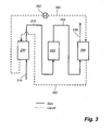
- Fig. 3 illustrates, in a schematic manner, the major steps of one embodiment of the method of the present invention.
- the method of cleaning a process gas comprises three major steps.
- a first step which is conducted in a first gas-liquid contacting device 250, comprises cooling the process gas, supplied via a duct 214, by means of bringing the process gas into direct contact with a cooling liquid, supplied via a pipe 252.
- a cooling liquid supplied via a pipe 252.
- This cooling liquid containing sulphate leaves the first gas-liquid contacting device 250 via a pipe 280.
- the cooled process gas having a temperature of about 0-20°C, leaves the first gas-liquid contacting device 250 via a duct 218.
- a second step which is conducted in a CO 2 -absorber 222, the cooled process gas is brought into contact with an ammoniated solution or slurry.
- the operation of the CO 2 -absorber 222 could be similar to what is described in the document WO 2006/022885 with reference to the CO 2 -absorber with reference number 134 in that document, and also similar to what has been described hereinbefore with reference to Fig. 1 of the present description.
- a regenerator is to be utilized, but is not illustrated in Fig. 3 for reasons of clarity of illustration.
- the process gas, from which at least a part of the carbon dioxide has been removed leaves the CO 2 -absorber 222 via a duct 244. Due to the process occurring in the CO 2 -absorber 222 the process gas leaving the CO 2 -absorber 222 via the duct 244 will contain some ammonia, typically about 100-1000 ppm of ammonia.
- a third step which is conducted in a second gas-liquid contacting device 294, the process gas containing ammonia, supplied via the duct 244, is brought into contact with the cooling liquid containing sulphate, which is supplied to the second gas-liquid contacting device 294 by means of the pipe 280.
- a cooler 282 such as a heat exchanger and/or a cooling tower, is connected to the pipe 280 and is operative for cooling the cooling liquid containing sulphate, before such liquid is introduced in the second gas-liquid contacting device 294.
- the ammonia of the process gas containing ammonia is at least partly absorbed into the cooling liquid containing sulphate.
- the process gas containing ammonia cools the cooling liquid containing sulphate.
- the cooling liquid containing sulphate leaves the second gas-liquid contacting device 294 via the pipe 252, and is recirculated back to the first gas-liquid contacting device 250.
- the process gas, from which ammonia has been removed, leaves the second gas-liquid contacting device 294 via a clean gas duct 246, and may be released to the atmosphere.
- concentration of ammonium sulphate in the circulating cooling liquid will increase over time, and that a bleed-off will be required, not illustrated in Fig. 3 .
- a gas cleaning system 1 which is operative for cleaning a process gas containing carbon dioxide and sulphur dioxide, comprises a combined cooling and cleaning system 16, and a CO 2 -absorber 22.
- the combined cooling and cleaning system 16 comprises a first gas-liquid contacting device 50 located upstream of the CO 2 -absorber 22 and operative for cooling the process gas by means of a cooling liquid, and for absorbing into the cooling liquid sulphur dioxide of the process gas, such that a cooling liquid containing sulphate is obtained.
- the combined cooling and cleaning system 16 further comprises a second gas-liquid contacting device 94 located downstream of the CO 2 -absorber 22 and operative for removing ammonia from the process gas, which has been treated in the CO 2 -absorber 22, by means of bringing the process gas containing ammonia into contact with the cooling liquid containing sulphate.
- a second gas-liquid contacting device 94 located downstream of the CO 2 -absorber 22 and operative for removing ammonia from the process gas, which has been treated in the CO 2 -absorber 22, by means of bringing the process gas containing ammonia into contact with the cooling liquid containing sulphate.
Landscapes
- Engineering & Computer Science (AREA)
- Chemical & Material Sciences (AREA)
- Oil, Petroleum & Natural Gas (AREA)
- Environmental & Geological Engineering (AREA)
- Chemical Kinetics & Catalysis (AREA)
- Analytical Chemistry (AREA)
- General Chemical & Material Sciences (AREA)
- Biomedical Technology (AREA)
- Health & Medical Sciences (AREA)
- Mechanical Engineering (AREA)
- General Engineering & Computer Science (AREA)
- Treating Waste Gases (AREA)
- Gas Separation By Absorption (AREA)
Claims (15)
- Verfahren zum Reinigen eines kohlendioxid- und schwefeloxidhaltigen Prozessgases, umfassend die folgenden Schritte:Kühlen des Prozessgases durch direktes Inkontaktbringen mit einer Kühlflüssigkeit und Absorbieren mindestens eines Teils des Schwefeldioxids des Prozessgases in die Kühlflüssigkeit, sodass eine sulfathaltige Kühlflüssigkeit erhalten wird,Inkontaktbringen des gekühlten Prozessgases mit einer ammoniakalischen Lösung oder Aufschlämmung, um Kohlendioxid mindestens teilweise aus dem Prozessgas zu entfernen und ein ammoniakhaltiges Prozessgas zu bilden, undmindestens teilweise Entfernen des Ammoniaks aus dem ammoniakhaltigen Prozessgas durch direktes Inkontaktbringen des ammoniakhaltigen Prozessgases mit der sulfathaltigen Kühlflüssigkeit.
- Verfahren nach Anspruch 1, wobei die sulfathaltige Kühlflüssigkeit durch das ammoniakhaltige Prozessgas gekühlt wird, wobei die dadurch gekühlte Kühlflüssigkeit beim Kühlen des Prozessgases benutzt wird.
- Verfahren nach Anspruch 1, wobei das Prozessgas gekühlt wird und das Schwefeldioxid durch die Verwendung einer ersten Gas-Flüssigkeits-Kontaktiervorrichtung (50; 250) in die Kühlflüssigkeit absorbiert wird und wobei Ammoniak aus dem ammoniakhaltigen Prozessgas durch die sulfathaltige Kühlflüssigkeit durch die Verwendung einer zweiten Gas-Flüssigkeits-Kontaktiervorrichtung (94; 294) entfernt wird.
- Verfahren nach Anspruch 1, wobei das Ammoniak des ammoniakhaltigen Prozessgases und das Sulfat der sulfathaltigen Kühlflüssigkeit mindestens teilweise reagieren, um Ammoniumsulfat in wässriger Lösung zu bilden.
- Verfahren nach Anspruch 1, wobei die Kühlflüssigkeit, die zum Kühlen des Prozessgases verwendet wird, in einem Wärmetauscher (82) zur Energierückgewinnung behandelt wird.
- Verfahren nach Anspruch 1, wobei der pH-Wert der sulfathaltigen Kühlflüssigkeit derart gesteuert wird, dass er in einem Bereich von 4 bis 6 liegt.
- Verfahren nach Anspruch 1, wobei das Prozessgas vor seiner Abkühlung in einer Schwefeldioxid-Entfernungsvorrichtung (12) behandelt wird, um einen Teil seines Schwefeldioxidgehalts zu entfernen, wobei die Effizienz der Schwefeldioxid-Entfernungsvorrichtung (12) gesteuert wird, um ein Prozessgas zu erhalten, das eine Schwefeldioxidmenge umfasst, die ein Verhältnis auf molekularer Basis zu der Ammoniakmenge des ammoniakhaltigen Prozessgases von 1:2 aufweist.
- Verfahren nach Anspruch 1, wobei das Ammoniak aus dem ammoniakhaltigen Prozessgas durch eine Wasserwäschevorrichtung (38) teilweise entfernt wird, wobei die Effizienz der Wasserwäschevorrichtung (38) gesteuert wird, um ein ammoniakhaltiges Prozessgas zu erhalten, das eine Ammoniakmenge umfasst, die ein Verhältnis auf molekularer Basis zu der Schwefeldioxidmenge des Prozessgases von 2:1 aufweist.
- Verfahren nach Anspruch 1, wobei Schwefelsäure zu der Kühlflüssigkeit gegeben wird, um ihren pH-Wert zu steuern.
- Gasreinigungssystem zum Reinigen eines kohlendioxid- und schwefeldioxidhaltigen Prozessgases, wobei das Gasreinigungssystem Folgendes umfasst:ein kombiniertes Kühl- und Reinigungssystem (16), das zum Kühlen des Prozessgases angeordnet ist; und ein Kohlendioxid-Entfernungssystem (20), umfassendeinen CO2-Absorber (22), der angeordnet ist, um Kohlendioxid mindestens teilweise aus dem Prozessgas zu entfernen, indem das gekühlte Prozessgas mit einer ammoniakalischen Lösung direkt in Kontakt gebracht wird, um mindestens einen Teil des Kohlendioxids zu absorbieren;wobei das kombinierte Kühl- und Reinigungssystem (16) Folgendes umfasst:eine erste Gas-Flüssigkeits-Kontaktiervorrichtung (50; 250), die sich in Bezug auf die beabsichtigte Strömungsrichtung des Prozessgases stromaufwärts des CO2-Absorbers (22; 222) befindet und zum Kühlen des Prozessgases durch direktes Inkontaktbringen des Prozessgases mit einer Kühlflüssigkeit angeordnet ist; undeine zweite Gas-Flüssigkeits-Kontaktiervorrichtung (94; 294), die sich in Bezug auf die beabsichtigte Strömungsrichtung des Prozessgases stromabwärts des CO2-Absorbers (22; 222) befindet und zum mindestens teilweise Entfernen von Ammoniak aus dem Prozessgas angeordnet ist, das in dem CO2-Absorber (22; 222) behandelt wird, indem das ammoniakhaltige Prozessgas mit der Kühlflüssigkeit aus der ersten Gas-Flüssigkeits-Kontaktiervorrichtung (50; 250) direkt in Kontakt gebracht wird;wobei das System gekennzeichnet ist durch:Rohrleitungen (80, 86, 92), die zum Weiterleiten der Kühlflüssigkeit aus der ersten Gas-Flüssigkeits-Kontaktiervorrichtung (50; 250) zu der zweiten Gas-Flüssigkeits-Kontaktiervorrichtung (94; 294) angeordnet sind.
- Gasreinigungssystem nach Anspruch 10, wobei die zweite Gas-Flüssigkeits-Kontaktiervorrichtung (94; 294) zum Kühlen der Kühlflüssigkeit durch das Prozessgas angeordnet ist und wobei eine Flüssigkeitstransportvorrichtung (52, 106) zur Rückführung mindestens eines Teils der gekühlten Kühlflüssigkeit aus der zweiten Gas-Flüssigkeits-Kontaktiervorrichtung (94; 294) zu der ersten Gas-Flüssigkeits-Kontaktiervorrichtung (50; 250) angeordnet ist.
- Gasreinigungssystem nach Anspruch 10, ferner umfassend eine Schwefeldioxid-Entfernungsvorrichtung (12), die sich in Bezug auf die beabsichtigte Strömungsrichtung des Prozessgases stromaufwärts der ersten Gas-Flüssigkeits-Kontaktiervorrichtung (50; 250) befindet und die zum Entfernen eines Teils des Schwefeldioxidgehalts des Prozessgases angeordnet ist, wobei die Effizienz der Schwefeldioxid-Entfernungsvorrichtung (12) steuerbar ist, um ein Prozessgas zu erhalten, das in der ersten Gas-Flüssigkeits-Kontaktiervorrichtung (50; 250) behandelt werden soll und das ein Verhältnis auf molekularer Basis zu einer Ammoniakmenge des in der zweiten Gas-Flüssigkeits-Kontaktiervorrichtung (94; 294) zu behandelnden Prozessgases von 1:2 aufweist.
- Gasreinigungssystem nach Anspruch 10, wobei das Kohlendioxid-Entfernungssystem (20) ferner eine Wasserwäschevorrichtung (38) umfasst, die sich in Bezug auf die beabsichtigte Strömungsrichtung des Prozessgases stromaufwärts der zweiten Gas-Flüssigkeits-Kontaktiervorrichtung (94; 294) befindet und die zum Entfernen eines Teils des Ammoniakgehalts des ammoniakhaltigen Prozessgases angeordnet ist, wobei die Effizienz der Wasserwäschevorrichtung (38) steuerbar ist, um ein Prozessgas zu erhalten, das in der zweiten Gas-Flüssigkeits-Kontaktiervorrichtung (94; 294) behandelt werden soll und das eine Ammoniakmenge umfasst, die ein Verhältnis auf molekularer Basis zu der Schwefeldioxidmenge des in ersten Gas-Flüssigkeits-Kontaktiervorrichtung (50; 250) zu behandelnden Prozessgases von 2:1 aufweist.
- Gasreinigungssystem nach Anspruch 10, wobei das kombinierte Kühl- und Reinigungssystem (16) eine Steuervorrichtung (116) umfasst, die zum Steuern des pH-Wertes der sulfathaltigen Kühlflüssigkeit angeordnet ist.
- Gasreinigungssystem nach Anspruch 10, wobei das kombinierte Kühl- und Reinigungssystem (16) einen Wärmetauscher (82) umfasst, der zum Rückgewinnen von Energie aus der Kühlflüssigkeit angeordnet ist, die zum Kühlen des Prozessgases in der ersten Gas-Flüssigkeitsvorrichtung (50; 250) benutzt wurde.
Priority Applications (1)
| Application Number | Priority Date | Filing Date | Title |
|---|---|---|---|
| PL08713849T PL2109490T3 (pl) | 2007-01-31 | 2008-01-21 | Zastosowanie SO2 ze spalin do odmywania amoniaku w warunkach kwaśnych |
Applications Claiming Priority (3)
| Application Number | Priority Date | Filing Date | Title |
|---|---|---|---|
| US88735707P | 2007-01-31 | 2007-01-31 | |
| US12/015,759 US7867322B2 (en) | 2007-01-31 | 2008-01-17 | Use of SO2 from flue gas for acid wash of ammonia |
| PCT/US2008/051536 WO2008094777A1 (en) | 2007-01-31 | 2008-01-21 | Use of so2 from flue gas for acid wash of ammonia |
Publications (2)
| Publication Number | Publication Date |
|---|---|
| EP2109490A1 EP2109490A1 (de) | 2009-10-21 |
| EP2109490B1 true EP2109490B1 (de) | 2012-08-15 |
Family
ID=39666466
Family Applications (1)
| Application Number | Title | Priority Date | Filing Date |
|---|---|---|---|
| EP08713849A Active EP2109490B1 (de) | 2007-01-31 | 2008-01-21 | Verwendung von so2 aus rauchgas für säurewäsche von ammoniak |
Country Status (15)
| Country | Link |
|---|---|
| US (1) | US7867322B2 (de) |
| EP (1) | EP2109490B1 (de) |
| JP (1) | JP4988864B2 (de) |
| KR (1) | KR101111997B1 (de) |
| CN (1) | CN101600489B (de) |
| AU (1) | AU2008210850B2 (de) |
| BR (1) | BRPI0806859A2 (de) |
| CA (1) | CA2675503C (de) |
| DK (1) | DK2109490T3 (de) |
| IL (1) | IL199720A (de) |
| MX (1) | MX2009007317A (de) |
| PL (1) | PL2109490T3 (de) |
| RU (1) | RU2009132522A (de) |
| WO (1) | WO2008094777A1 (de) |
| ZA (1) | ZA200904795B (de) |
Families Citing this family (70)
| Publication number | Priority date | Publication date | Assignee | Title |
|---|---|---|---|---|
| EP1781400B1 (de) | 2004-08-06 | 2013-07-03 | ALSTOM Technology Ltd | Reinigung von verbrennungsabgas mit entfernung von co2 |
| EP2014347A1 (de) * | 2007-07-03 | 2009-01-14 | ALSTOM Technology Ltd | Entfernung von Kohlendioxid aus Rauchgas |
| CN101687137A (zh) * | 2007-07-12 | 2010-03-31 | 鲍尔斯潘公司 | 用硝酸铵尿素溶液洗除氨气体 |
| CA2697369A1 (en) * | 2007-08-24 | 2009-03-05 | Powerspan Corp | Method and apparatus for producing ammonium carbonate from urea |
| US8182577B2 (en) * | 2007-10-22 | 2012-05-22 | Alstom Technology Ltd | Multi-stage CO2 removal system and method for processing a flue gas stream |
| GB0721488D0 (en) * | 2007-11-01 | 2007-12-12 | Alstom Technology Ltd | Carbon capture system |
| US7862788B2 (en) * | 2007-12-05 | 2011-01-04 | Alstom Technology Ltd | Promoter enhanced chilled ammonia based system and method for removal of CO2 from flue gas stream |
| US8192530B2 (en) | 2007-12-13 | 2012-06-05 | Alstom Technology Ltd | System and method for regeneration of an absorbent solution |
| WO2009091437A1 (en) * | 2008-01-18 | 2009-07-23 | Powerspan Corp. | Removal of carbon dioxide from a flue gas stream |
| US20090282977A1 (en) * | 2008-05-14 | 2009-11-19 | Alstom Technology Ltd | Gas purification system having provisions for co2 injection of wash water |
| ATE534022T1 (de) * | 2008-07-29 | 2011-12-15 | Powerspan Corp | Verfahren zur reinigung der verteilerplatte in einem flüssigbettreaktorsystem |
| WO2010020017A1 (en) * | 2008-08-22 | 2010-02-25 | Commonwealth Scientific And Industrial Research Organisation | Treatment of co2-depleted flue gases |
| TW201016702A (en) | 2008-09-25 | 2010-05-01 | Shionogi & Co | Novel pyrrolinone derivative and pharmaceutical composition comprising the same |
| US7846240B2 (en) * | 2008-10-02 | 2010-12-07 | Alstom Technology Ltd | Chilled ammonia based CO2 capture system with water wash system |
| US8404027B2 (en) | 2008-11-04 | 2013-03-26 | Alstom Technology Ltd | Reabsorber for ammonia stripper offgas |
| FR2940413B1 (fr) * | 2008-12-19 | 2013-01-11 | Air Liquide | Procede de capture du co2 par cryo-condensation |
| US8292989B2 (en) * | 2009-10-30 | 2012-10-23 | Alstom Technology Ltd | Gas stream processing |
| US8845789B2 (en) | 2009-03-31 | 2014-09-30 | Alstom Technology Ltd | Process for CO2 capture with improved stripper performance |
| US8784761B2 (en) | 2009-11-20 | 2014-07-22 | Alstom Technology Ltd | Single absorber vessel to capture CO2 |
| US8309047B2 (en) | 2009-09-15 | 2012-11-13 | Alstom Technology Ltd | Method and system for removal of carbon dioxide from a process gas |
| US8518156B2 (en) * | 2009-09-21 | 2013-08-27 | Alstom Technology Ltd | Method and system for regenerating a solution used in a wash vessel |
| US20110068585A1 (en) * | 2009-09-24 | 2011-03-24 | Alstom Technology Ltd | Method and system for capturing and utilizing energy generated in a flue gas stream processing system |
| EP2322265A1 (de) | 2009-11-12 | 2011-05-18 | Alstom Technology Ltd | Rauchgasbehandlungssystem |
| KR101039624B1 (ko) | 2009-11-17 | 2011-06-09 | 한국에너지기술연구원 | 암모니아수를 이용한 이산화탄소 포집 공정에서 배출되는 가스 내의 미량 암모니아를 제거하는 장치 |
| US8460436B2 (en) | 2009-11-24 | 2013-06-11 | Alstom Technology Ltd | Advanced intercooling and recycling in CO2 absorption |
| EP2335804B1 (de) * | 2009-12-04 | 2014-09-10 | Alstom Technology Ltd | Verfahren und Vorrichtung zum Reinigen eines kohlenstoffdioxidreichen Abgases |
| EP2335806A1 (de) * | 2009-12-04 | 2011-06-22 | Alstom Technology Ltd | Verfahren und System zum Kondensieren von Wasserdampf eines kohlenstoffdioxidreichen Abgases |
| US8293200B2 (en) * | 2009-12-17 | 2012-10-23 | Alstom Technology Ltd | Desulfurization of, and removal of carbon dioxide from, gas mixtures |
| JP5638262B2 (ja) * | 2010-02-23 | 2014-12-10 | 三菱重工業株式会社 | Co2回収装置およびco2回収方法 |
| GB201012439D0 (en) * | 2010-07-24 | 2010-09-08 | Sevier David | Process for capture of gases from gas streams |
| US8728209B2 (en) | 2010-09-13 | 2014-05-20 | Alstom Technology Ltd | Method and system for reducing energy requirements of a CO2 capture system |
| US8623307B2 (en) | 2010-09-14 | 2014-01-07 | Alstom Technology Ltd. | Process gas treatment system |
| EP2457637B8 (de) * | 2010-11-24 | 2016-09-21 | General Electric Technology GmbH | Verfahren und Boilersystem zum Reinigen eines kohlendioxidreichen Abgases |
| EP2481470A1 (de) * | 2011-02-01 | 2012-08-01 | ALSTOM Technology Ltd | Prozessgasbehandlungssystem |
| WO2012104202A1 (en) * | 2011-02-01 | 2012-08-09 | Alstom Technology Ltd | Combined cycle power plant with co2 capture plant |
| US8329128B2 (en) * | 2011-02-01 | 2012-12-11 | Alstom Technology Ltd | Gas treatment process and system |
| US9028784B2 (en) * | 2011-02-15 | 2015-05-12 | Alstom Technology Ltd | Process and system for cleaning a gas stream |
| US8858905B2 (en) * | 2011-02-16 | 2014-10-14 | Anhui Huaihua Co. Ltd. | System and process for trapping sulfur dioxide and carbon dioxide by ammonia absorption at atmospheric pressure |
| US9133407B2 (en) | 2011-02-25 | 2015-09-15 | Alstom Technology Ltd | Systems and processes for removing volatile degradation products produced in gas purification |
| ES2543313T3 (es) * | 2011-03-31 | 2015-08-18 | Basf Se | Retención de aminas en la separación de gases ácidos por medio de agentes de absorción de amina |
| JP2013000729A (ja) * | 2011-06-21 | 2013-01-07 | Toshiba Corp | 二酸化炭素回収装置および二酸化炭素回収方法 |
| JP5755047B2 (ja) * | 2011-06-22 | 2015-07-29 | 三菱重工業株式会社 | 排ガス処理システム及び排ガス処理方法 |
| US8623314B2 (en) | 2011-07-01 | 2014-01-07 | Alstom Technology Ltd | Chilled ammonia based CO2 capture system with ammonia recovery and processes of use |
| KR101725555B1 (ko) * | 2011-08-29 | 2017-04-11 | 한국전력공사 | 흡수효율이 향상된 이산화탄소 회수장치 및 회수방법 |
| US8864878B2 (en) | 2011-09-23 | 2014-10-21 | Alstom Technology Ltd | Heat integration of a cement manufacturing plant with an absorption based carbon dioxide capture process |
| US8470077B2 (en) | 2011-11-17 | 2013-06-25 | Alstom Technology Ltd | Low pressure stripping in a gas purification process and systems thereof |
| US9492786B2 (en) | 2011-11-22 | 2016-11-15 | Fluor Corporation | Multi-purpose absorber |
| US8882896B2 (en) * | 2011-12-02 | 2014-11-11 | Fluor Technologies Corporation | Multi-directional outlet transition and hood |
| US8911538B2 (en) | 2011-12-22 | 2014-12-16 | Alstom Technology Ltd | Method and system for treating an effluent stream generated by a carbon capture system |
| US9162177B2 (en) | 2012-01-25 | 2015-10-20 | Alstom Technology Ltd | Ammonia capturing by CO2 product liquid in water wash liquid |
| US9028654B2 (en) | 2012-02-29 | 2015-05-12 | Alstom Technology Ltd | Method of treatment of amine waste water and a system for accomplishing the same |
| US20130259780A1 (en) * | 2012-03-30 | 2013-10-03 | Alstom Technology Ltd | Method for controlling solvent emissions from a carbon capture unit |
| US8864879B2 (en) | 2012-03-30 | 2014-10-21 | Jalal Askander | System for recovery of ammonia from lean solution in a chilled ammonia process utilizing residual flue gas |
| EP2653210A1 (de) * | 2012-04-18 | 2013-10-23 | Siemens Aktiengesellschaft | Verbrennungsanlage mit Rauchgaswascher und CO2-Abscheidung sowie Verfahren zu deren Betrieb |
| EP2689820A1 (de) | 2012-07-27 | 2014-01-29 | Nederlandse Organisatie voor toegepast -natuurwetenschappelijk onderzoek TNO | Aminreduktion in Aerosolen |
| US8545782B1 (en) * | 2012-10-16 | 2013-10-01 | Mitsubishi Heavy Industries, Ltd. | CO2 recovery apparatus and CO2 recovery method |
| KR101937801B1 (ko) * | 2012-12-24 | 2019-04-11 | 재단법인 포항산업과학연구원 | 배기가스로부터 이산화탄소 및 황산화물을 제거하는 방법 및 제거 장치 |
| US9101912B2 (en) | 2012-11-05 | 2015-08-11 | Alstom Technology Ltd | Method for regeneration of solid amine CO2 capture beds |
| EP2754480B1 (de) | 2013-01-09 | 2022-05-11 | General Electric Technology GmbH | Abgasbehandlungsverfahren und -anlage zur Entfernung von Kohlendioxid, Schwefeldioxid, Partikeln und Schwermetallen |
| US9447996B2 (en) | 2013-01-15 | 2016-09-20 | General Electric Technology Gmbh | Carbon dioxide removal system using absorption refrigeration |
| KR101353431B1 (ko) | 2013-03-13 | 2014-01-20 | 양미혜 | 가스 냉각 장치 |
| US9939153B2 (en) | 2013-06-03 | 2018-04-10 | Washington University | Method and apparatus for capturing carbon dioxide during combustion of carbon containing fuel |
| US9192888B2 (en) * | 2013-06-26 | 2015-11-24 | Uop Llc | Apparatuses and methods for removing acid gas from sour gas |
| KR101496037B1 (ko) * | 2013-10-04 | 2015-02-26 | 이동훈 | 배기가스의 폐열 회수 및 백연 저감 방법 및 장치 |
| US8986640B1 (en) | 2014-01-07 | 2015-03-24 | Alstom Technology Ltd | System and method for recovering ammonia from a chilled ammonia process |
| CN104645808B (zh) * | 2015-01-13 | 2018-05-29 | 清华大学 | 烟气的处理方法及系统 |
| LU100469B1 (en) * | 2017-10-09 | 2019-04-09 | Cppe Carbon Process & Plant Eng S A | Elimination of SO2 and CO2 from a gas |
| DE112020007643A5 (de) * | 2020-10-02 | 2023-07-20 | Engineering Dobersek GmbH | VERFAHREN UND VORRICHTUNG ZUR RAUCHGASENTSCHWEFELUNG, INSBESONDERE ZUR ENTSCHWEFELUNG VON ABGASEN AUS GROßTECHNISCHEN PYROMETALLURGISCHEN PROZESSEN MIT HOHEN SCHWEFELDIOXID-GEHALTEN |
| CN114917743A (zh) | 2022-05-19 | 2022-08-19 | 江苏新世纪江南环保股份有限公司 | 一种控制氨法脱碳系统氨逃逸的装置及方法 |
| CN115090099A (zh) * | 2022-06-20 | 2022-09-23 | 江苏新世纪江南环保股份有限公司 | 一种氨法脱碳系统中脱除杂质的方法 |
Family Cites Families (13)
| Publication number | Priority date | Publication date | Assignee | Title |
|---|---|---|---|---|
| US454199A (en) * | 1891-06-16 | Riveting-machine | ||
| US4369167A (en) * | 1972-03-24 | 1983-01-18 | Weir Jr Alexander | Process for treating stack gases |
| US3969482A (en) * | 1974-04-25 | 1976-07-13 | Teller Environmental Systems, Inc. | Abatement of high concentrations of acid gas emissions |
| DE3220403C1 (de) * | 1982-05-29 | 1983-11-17 | Buckau-Walther AG, 4048 Grevenbroich | Verfahren zum Entfernen von sauren Komponenten und Stickoxyden aus Abgasen |
| US4834959A (en) * | 1986-03-10 | 1989-05-30 | The Dow Chemical Company | Process for selectively removing sulfur dioxide |
| JP2000506062A (ja) * | 1996-03-01 | 2000-05-23 | 株式会社 荏原製作所 | 電子ビーム照射による脱硫方法及び装置 |
| US6302945B1 (en) * | 1999-06-11 | 2001-10-16 | Electric Power Research Institute, Incorporated | Electrostatic precipitator for removing SO2 |
| US20030131731A1 (en) * | 2001-12-20 | 2003-07-17 | Koros William J. | Crosslinked and crosslinkable hollow fiber mixed matrix membrane and method of making same |
| JP3814206B2 (ja) * | 2002-01-31 | 2006-08-23 | 三菱重工業株式会社 | 二酸化炭素回収プロセスの排熱利用方法 |
| EP1781400B1 (de) | 2004-08-06 | 2013-07-03 | ALSTOM Technology Ltd | Reinigung von verbrennungsabgas mit entfernung von co2 |
| FI118629B (fi) | 2005-06-15 | 2008-01-31 | Metso Power Oy | Menetelmä ja laitteisto hiilidioksidin poistamiseksi rikkidioksidipitoisista savukaasuista |
| US7384616B2 (en) | 2005-06-20 | 2008-06-10 | Cansolv Technologies Inc. | Waste gas treatment process including removal of mercury |
| US7569198B2 (en) * | 2006-08-25 | 2009-08-04 | Exxonmobil Research & Engineering Company | Wet gas scrubbing process |
-
2008
- 2008-01-17 US US12/015,759 patent/US7867322B2/en active Active
- 2008-01-21 CA CA2675503A patent/CA2675503C/en not_active Expired - Fee Related
- 2008-01-21 EP EP08713849A patent/EP2109490B1/de active Active
- 2008-01-21 WO PCT/US2008/051536 patent/WO2008094777A1/en not_active Ceased
- 2008-01-21 MX MX2009007317A patent/MX2009007317A/es active IP Right Grant
- 2008-01-21 CN CN2008800037507A patent/CN101600489B/zh active Active
- 2008-01-21 ZA ZA200904795A patent/ZA200904795B/xx unknown
- 2008-01-21 KR KR1020097017754A patent/KR101111997B1/ko not_active Expired - Fee Related
- 2008-01-21 RU RU2009132522/05A patent/RU2009132522A/ru not_active Application Discontinuation
- 2008-01-21 BR BRPI0806859-3A2A patent/BRPI0806859A2/pt not_active IP Right Cessation
- 2008-01-21 DK DK08713849.1T patent/DK2109490T3/da active
- 2008-01-21 AU AU2008210850A patent/AU2008210850B2/en not_active Ceased
- 2008-01-21 JP JP2009548358A patent/JP4988864B2/ja not_active Expired - Fee Related
- 2008-01-21 PL PL08713849T patent/PL2109490T3/pl unknown
-
2009
- 2009-07-07 IL IL199720A patent/IL199720A/en not_active IP Right Cessation
Also Published As
| Publication number | Publication date |
|---|---|
| CN101600489B (zh) | 2012-11-14 |
| EP2109490A1 (de) | 2009-10-21 |
| JP4988864B2 (ja) | 2012-08-01 |
| US7867322B2 (en) | 2011-01-11 |
| AU2008210850A1 (en) | 2008-08-07 |
| PL2109490T3 (pl) | 2013-01-31 |
| CN101600489A (zh) | 2009-12-09 |
| US20080178733A1 (en) | 2008-07-31 |
| MX2009007317A (es) | 2009-08-12 |
| CA2675503C (en) | 2012-12-04 |
| BRPI0806859A2 (pt) | 2014-06-17 |
| KR101111997B1 (ko) | 2012-02-17 |
| ZA200904795B (en) | 2010-09-29 |
| KR20090104126A (ko) | 2009-10-05 |
| IL199720A (en) | 2013-01-31 |
| AU2008210850B2 (en) | 2012-08-02 |
| JP2010516464A (ja) | 2010-05-20 |
| IL199720A0 (en) | 2010-04-15 |
| CA2675503A1 (en) | 2008-08-07 |
| RU2009132522A (ru) | 2011-03-10 |
| DK2109490T3 (da) | 2012-11-05 |
| WO2008094777A1 (en) | 2008-08-07 |
Similar Documents
| Publication | Publication Date | Title |
|---|---|---|
| EP2109490B1 (de) | Verwendung von so2 aus rauchgas für säurewäsche von ammoniak | |
| JP4995084B2 (ja) | Co2の除去を包含する燃焼ガスの超清浄化 | |
| CA2824149C (en) | Gas treatment process and system | |
| US8623314B2 (en) | Chilled ammonia based CO2 capture system with ammonia recovery and processes of use | |
| US8292989B2 (en) | Gas stream processing | |
| KR20130116276A (ko) | 배기가스 처리방법과 장치 | |
| JP2015166090A (ja) | 排ガス処理システム及び方法 | |
| US9951656B2 (en) | Method of exhaust gas treatment for a gas turbine system and exhaust gas treatment assembly | |
| EP2675549B1 (de) | Verfahren zur reinigung eines gasstroms | |
| US20140105800A1 (en) | Method for processing a power plant flue gas | |
| JP2014128775A (ja) | 排ガス処理設備およびこれを用いるガスタービン発電システム | |
| EP2411120A1 (de) | Gasstrombehandlung | |
| JP3305001B2 (ja) | 燃焼排ガス中の二酸化炭素と硫黄酸化物を除去する方法 | |
| KR20230094529A (ko) | 이산화탄소 포집공정과 탈질공정이 연계된 배가스 처리방법 | |
| CN221788840U (zh) | 催化裂化再生烟气处理装置以及催化裂化再生系统 | |
| CN106039940A (zh) | 废气脱硫脱硝的废酸回收利用装置 |
Legal Events
| Date | Code | Title | Description |
|---|---|---|---|
| PUAI | Public reference made under article 153(3) epc to a published international application that has entered the european phase |
Free format text: ORIGINAL CODE: 0009012 |
|
| 17P | Request for examination filed |
Effective date: 20090731 |
|
| AK | Designated contracting states |
Kind code of ref document: A1 Designated state(s): AT BE BG CH CY CZ DE DK EE ES FI FR GB GR HR HU IE IS IT LI LT LU LV MC MT NL NO PL PT RO SE SI SK TR |
|
| DAX | Request for extension of the european patent (deleted) | ||
| 17Q | First examination report despatched |
Effective date: 20101015 |
|
| GRAP | Despatch of communication of intention to grant a patent |
Free format text: ORIGINAL CODE: EPIDOSNIGR1 |
|
| GRAS | Grant fee paid |
Free format text: ORIGINAL CODE: EPIDOSNIGR3 |
|
| GRAA | (expected) grant |
Free format text: ORIGINAL CODE: 0009210 |
|
| AK | Designated contracting states |
Kind code of ref document: B1 Designated state(s): AT BE BG CH CY CZ DE DK EE ES FI FR GB GR HR HU IE IS IT LI LT LU LV MC MT NL NO PL PT RO SE SI SK TR |
|
| REG | Reference to a national code |
Ref country code: GB Ref legal event code: FG4D Ref country code: CH Ref legal event code: EP Ref country code: AT Ref legal event code: REF Ref document number: 570505 Country of ref document: AT Kind code of ref document: T Effective date: 20120815 |
|
| REG | Reference to a national code |
Ref country code: IE Ref legal event code: FG4D |
|
| REG | Reference to a national code |
Ref country code: SE Ref legal event code: TRGR |
|
| REG | Reference to a national code |
Ref country code: DE Ref legal event code: R096 Ref document number: 602008018010 Country of ref document: DE Effective date: 20121011 |
|
| REG | Reference to a national code |
Ref country code: DK Ref legal event code: T3 |
|
| REG | Reference to a national code |
Ref country code: RO Ref legal event code: EPE |
|
| REG | Reference to a national code |
Ref country code: NL Ref legal event code: T3 |
|
| REG | Reference to a national code |
Ref country code: NO Ref legal event code: T2 Effective date: 20120815 |
|
| REG | Reference to a national code |
Ref country code: GR Ref legal event code: EP Ref document number: 20120402507 Country of ref document: GR Effective date: 20121122 |
|
| PG25 | Lapsed in a contracting state [announced via postgrant information from national office to epo] |
Ref country code: HR Free format text: LAPSE BECAUSE OF FAILURE TO SUBMIT A TRANSLATION OF THE DESCRIPTION OR TO PAY THE FEE WITHIN THE PRESCRIBED TIME-LIMIT Effective date: 20120815 Ref country code: LT Free format text: LAPSE BECAUSE OF FAILURE TO SUBMIT A TRANSLATION OF THE DESCRIPTION OR TO PAY THE FEE WITHIN THE PRESCRIBED TIME-LIMIT Effective date: 20120815 Ref country code: IS Free format text: LAPSE BECAUSE OF FAILURE TO SUBMIT A TRANSLATION OF THE DESCRIPTION OR TO PAY THE FEE WITHIN THE PRESCRIBED TIME-LIMIT Effective date: 20121215 |
|
| REG | Reference to a national code |
Ref country code: PL Ref legal event code: T3 |
|
| PG25 | Lapsed in a contracting state [announced via postgrant information from national office to epo] |
Ref country code: LV Free format text: LAPSE BECAUSE OF FAILURE TO SUBMIT A TRANSLATION OF THE DESCRIPTION OR TO PAY THE FEE WITHIN THE PRESCRIBED TIME-LIMIT Effective date: 20120815 Ref country code: SI Free format text: LAPSE BECAUSE OF FAILURE TO SUBMIT A TRANSLATION OF THE DESCRIPTION OR TO PAY THE FEE WITHIN THE PRESCRIBED TIME-LIMIT Effective date: 20120815 Ref country code: PT Free format text: LAPSE BECAUSE OF FAILURE TO SUBMIT A TRANSLATION OF THE DESCRIPTION OR TO PAY THE FEE WITHIN THE PRESCRIBED TIME-LIMIT Effective date: 20121217 |
|
| PG25 | Lapsed in a contracting state [announced via postgrant information from national office to epo] |
Ref country code: EE Free format text: LAPSE BECAUSE OF FAILURE TO SUBMIT A TRANSLATION OF THE DESCRIPTION OR TO PAY THE FEE WITHIN THE PRESCRIBED TIME-LIMIT Effective date: 20120815 Ref country code: ES Free format text: LAPSE BECAUSE OF FAILURE TO SUBMIT A TRANSLATION OF THE DESCRIPTION OR TO PAY THE FEE WITHIN THE PRESCRIBED TIME-LIMIT Effective date: 20121126 |
|
| PG25 | Lapsed in a contracting state [announced via postgrant information from national office to epo] |
Ref country code: SK Free format text: LAPSE BECAUSE OF FAILURE TO SUBMIT A TRANSLATION OF THE DESCRIPTION OR TO PAY THE FEE WITHIN THE PRESCRIBED TIME-LIMIT Effective date: 20120815 Ref country code: CY Free format text: LAPSE BECAUSE OF FAILURE TO SUBMIT A TRANSLATION OF THE DESCRIPTION OR TO PAY THE FEE WITHIN THE PRESCRIBED TIME-LIMIT Effective date: 20120815 |
|
| PLBE | No opposition filed within time limit |
Free format text: ORIGINAL CODE: 0009261 |
|
| STAA | Information on the status of an ep patent application or granted ep patent |
Free format text: STATUS: NO OPPOSITION FILED WITHIN TIME LIMIT |
|
| 26N | No opposition filed |
Effective date: 20130516 |
|
| PG25 | Lapsed in a contracting state [announced via postgrant information from national office to epo] |
Ref country code: BG Free format text: LAPSE BECAUSE OF FAILURE TO SUBMIT A TRANSLATION OF THE DESCRIPTION OR TO PAY THE FEE WITHIN THE PRESCRIBED TIME-LIMIT Effective date: 20121115 |
|
| PG25 | Lapsed in a contracting state [announced via postgrant information from national office to epo] |
Ref country code: MC Free format text: LAPSE BECAUSE OF NON-PAYMENT OF DUE FEES Effective date: 20130131 |
|
| REG | Reference to a national code |
Ref country code: CH Ref legal event code: PL |
|
| REG | Reference to a national code |
Ref country code: DE Ref legal event code: R097 Ref document number: 602008018010 Country of ref document: DE Effective date: 20130516 |
|
| REG | Reference to a national code |
Ref country code: IE Ref legal event code: MM4A |
|
| REG | Reference to a national code |
Ref country code: HU Ref legal event code: AG4A Ref document number: E017004 Country of ref document: HU |
|
| PG25 | Lapsed in a contracting state [announced via postgrant information from national office to epo] |
Ref country code: LI Free format text: LAPSE BECAUSE OF NON-PAYMENT OF DUE FEES Effective date: 20130131 Ref country code: CH Free format text: LAPSE BECAUSE OF NON-PAYMENT OF DUE FEES Effective date: 20130131 |
|
| PG25 | Lapsed in a contracting state [announced via postgrant information from national office to epo] |
Ref country code: IE Free format text: LAPSE BECAUSE OF NON-PAYMENT OF DUE FEES Effective date: 20130121 |
|
| PG25 | Lapsed in a contracting state [announced via postgrant information from national office to epo] |
Ref country code: MT Free format text: LAPSE BECAUSE OF FAILURE TO SUBMIT A TRANSLATION OF THE DESCRIPTION OR TO PAY THE FEE WITHIN THE PRESCRIBED TIME-LIMIT Effective date: 20120815 |
|
| PG25 | Lapsed in a contracting state [announced via postgrant information from national office to epo] |
Ref country code: TR Free format text: LAPSE BECAUSE OF FAILURE TO SUBMIT A TRANSLATION OF THE DESCRIPTION OR TO PAY THE FEE WITHIN THE PRESCRIBED TIME-LIMIT Effective date: 20120815 |
|
| REG | Reference to a national code |
Ref country code: FR Ref legal event code: PLFP Year of fee payment: 9 |
|
| PGFP | Annual fee paid to national office [announced via postgrant information from national office to epo] |
Ref country code: GR Payment date: 20160121 Year of fee payment: 9 |
|
| REG | Reference to a national code |
Ref country code: DE Ref legal event code: R082 Ref document number: 602008018010 Country of ref document: DE Representative=s name: RUEGER | ABEL PATENT- UND RECHTSANWAELTE, DE Ref country code: DE Ref legal event code: R082 Ref document number: 602008018010 Country of ref document: DE Representative=s name: RUEGER ABEL PATENTANWAELTE PARTGMBB, DE Ref country code: DE Ref legal event code: R082 Ref document number: 602008018010 Country of ref document: DE Representative=s name: RUEGER, BARTHELT & ABEL, DE Ref country code: DE Ref legal event code: R082 Ref document number: 602008018010 Country of ref document: DE Representative=s name: RUEGER ABEL PATENT- UND RECHTSANWAELTE, DE |
|
| REG | Reference to a national code |
Ref country code: NO Ref legal event code: CHAD Owner name: GENERAL ELECTRIC TECHNOLOGY GMBH, CH Ref country code: NO Ref legal event code: CREP Representative=s name: BRYN AARFLOT AS, POSTBOKS 449 SENTRUM, 0104 OSLO |
|
| REG | Reference to a national code |
Ref country code: NL Ref legal event code: HC Owner name: GENERAL ELECTRIC TECHNOLOGY GMBH; CH Free format text: DETAILS ASSIGNMENT: VERANDERING VAN EIGENAAR(S), VERANDERING VAN NAAM VAN DE EIGENAAR(S); FORMER OWNER NAME: ALSTOM TECHNOLOGY LTD Effective date: 20160623 |
|
| REG | Reference to a national code |
Ref country code: DE Ref legal event code: R082 Ref document number: 602008018010 Country of ref document: DE Representative=s name: RUEGER | ABEL PATENT- UND RECHTSANWAELTE, DE Ref country code: DE Ref legal event code: R082 Ref document number: 602008018010 Country of ref document: DE Representative=s name: RUEGER ABEL PATENTANWAELTE PARTGMBB, DE Ref country code: DE Ref legal event code: R082 Ref document number: 602008018010 Country of ref document: DE Representative=s name: RUEGER, BARTHELT & ABEL, DE Ref country code: DE Ref legal event code: R081 Ref document number: 602008018010 Country of ref document: DE Owner name: GENERAL ELECTRIC TECHNOLOGY GMBH, CH Free format text: FORMER OWNER: ALSTOM TECHNOLOGY LTD., BADEN, CH Ref country code: DE Ref legal event code: R082 Ref document number: 602008018010 Country of ref document: DE Representative=s name: RUEGER ABEL PATENT- UND RECHTSANWAELTE, DE |
|
| REG | Reference to a national code |
Ref country code: FR Ref legal event code: CD Owner name: ALSTOM TECHNOLOGY LTD, CH Effective date: 20161124 |
|
| REG | Reference to a national code |
Ref country code: FR Ref legal event code: PLFP Year of fee payment: 10 |
|
| REG | Reference to a national code |
Ref country code: HU Ref legal event code: HC9C Owner name: GENERAL ELECTRIC TECHNOLOGY GMBH., CH Free format text: FORMER OWNER(S): ALSTOM TECHNOLOGY LTD, CH |
|
| PGFP | Annual fee paid to national office [announced via postgrant information from national office to epo] |
Ref country code: NL Payment date: 20170126 Year of fee payment: 10 |
|
| PGFP | Annual fee paid to national office [announced via postgrant information from national office to epo] |
Ref country code: SE Payment date: 20170127 Year of fee payment: 10 Ref country code: FR Payment date: 20170125 Year of fee payment: 10 Ref country code: FI Payment date: 20170127 Year of fee payment: 10 Ref country code: RO Payment date: 20170105 Year of fee payment: 10 |
|
| PGFP | Annual fee paid to national office [announced via postgrant information from national office to epo] |
Ref country code: AT Payment date: 20170103 Year of fee payment: 10 Ref country code: PL Payment date: 20170102 Year of fee payment: 10 Ref country code: CZ Payment date: 20170110 Year of fee payment: 10 Ref country code: HU Payment date: 20170106 Year of fee payment: 10 Ref country code: BE Payment date: 20170127 Year of fee payment: 10 Ref country code: DK Payment date: 20170125 Year of fee payment: 10 Ref country code: GB Payment date: 20170127 Year of fee payment: 10 Ref country code: LU Payment date: 20170130 Year of fee payment: 10 |
|
| REG | Reference to a national code |
Ref country code: AT Ref legal event code: PC Ref document number: 570505 Country of ref document: AT Kind code of ref document: T Owner name: GENERAL ELECTRIC TECHNOLOGY GMBH, CH Effective date: 20170502 |
|
| PGFP | Annual fee paid to national office [announced via postgrant information from national office to epo] |
Ref country code: IT Payment date: 20170124 Year of fee payment: 10 |
|
| PG25 | Lapsed in a contracting state [announced via postgrant information from national office to epo] |
Ref country code: GR Free format text: LAPSE BECAUSE OF NON-PAYMENT OF DUE FEES Effective date: 20170811 |
|
| REG | Reference to a national code |
Ref country code: DK Ref legal event code: EBP Effective date: 20180131 |
|
| REG | Reference to a national code |
Ref country code: SE Ref legal event code: EUG |
|
| REG | Reference to a national code |
Ref country code: NL Ref legal event code: MM Effective date: 20180201 |
|
| REG | Reference to a national code |
Ref country code: AT Ref legal event code: MM01 Ref document number: 570505 Country of ref document: AT Kind code of ref document: T Effective date: 20180121 |
|
| GBPC | Gb: european patent ceased through non-payment of renewal fee |
Effective date: 20180121 |
|
| PG25 | Lapsed in a contracting state [announced via postgrant information from national office to epo] |
Ref country code: RO Free format text: LAPSE BECAUSE OF NON-PAYMENT OF DUE FEES Effective date: 20180121 Ref country code: SE Free format text: LAPSE BECAUSE OF NON-PAYMENT OF DUE FEES Effective date: 20180122 Ref country code: HU Free format text: LAPSE BECAUSE OF NON-PAYMENT OF DUE FEES Effective date: 20180122 Ref country code: FI Free format text: LAPSE BECAUSE OF NON-PAYMENT OF DUE FEES Effective date: 20180121 Ref country code: FR Free format text: LAPSE BECAUSE OF NON-PAYMENT OF DUE FEES Effective date: 20180131 Ref country code: LU Free format text: LAPSE BECAUSE OF NON-PAYMENT OF DUE FEES Effective date: 20180121 |
|
| REG | Reference to a national code |
Ref country code: FR Ref legal event code: ST Effective date: 20180928 |
|
| REG | Reference to a national code |
Ref country code: BE Ref legal event code: HC Owner name: GENERAL ELECTRIC TECHNOLOGY GMBH; CH Free format text: DETAILS ASSIGNMENT: CHANGE OF OWNER(S), CHANGEMENT NOM PROPRIETAIRE; FORMER OWNER NAME: ALSTOM TECHNOLOGY LTD Effective date: 20160705 Ref country code: BE Ref legal event code: MM Effective date: 20180131 |
|
| PG25 | Lapsed in a contracting state [announced via postgrant information from national office to epo] |
Ref country code: CZ Free format text: LAPSE BECAUSE OF NON-PAYMENT OF DUE FEES Effective date: 20180121 Ref country code: NL Free format text: LAPSE BECAUSE OF NON-PAYMENT OF DUE FEES Effective date: 20180201 Ref country code: GB Free format text: LAPSE BECAUSE OF NON-PAYMENT OF DUE FEES Effective date: 20180121 Ref country code: BE Free format text: LAPSE BECAUSE OF NON-PAYMENT OF DUE FEES Effective date: 20180131 Ref country code: AT Free format text: LAPSE BECAUSE OF NON-PAYMENT OF DUE FEES Effective date: 20180121 |
|
| PG25 | Lapsed in a contracting state [announced via postgrant information from national office to epo] |
Ref country code: DK Free format text: LAPSE BECAUSE OF NON-PAYMENT OF DUE FEES Effective date: 20180131 |
|
| PG25 | Lapsed in a contracting state [announced via postgrant information from national office to epo] |
Ref country code: IT Free format text: LAPSE BECAUSE OF NON-PAYMENT OF DUE FEES Effective date: 20180121 |
|
| PG25 | Lapsed in a contracting state [announced via postgrant information from national office to epo] |
Ref country code: PL Free format text: LAPSE BECAUSE OF NON-PAYMENT OF DUE FEES Effective date: 20180121 |
|
| PGFP | Annual fee paid to national office [announced via postgrant information from national office to epo] |
Ref country code: NO Payment date: 20251218 Year of fee payment: 19 |
|
| PGFP | Annual fee paid to national office [announced via postgrant information from national office to epo] |
Ref country code: DE Payment date: 20251217 Year of fee payment: 19 |