EP2109393B1 - Okularsensor zum nachweis eines analyten in einer augenflüssigkeit - Google Patents
Okularsensor zum nachweis eines analyten in einer augenflüssigkeit Download PDFInfo
- Publication number
- EP2109393B1 EP2109393B1 EP08701462.7A EP08701462A EP2109393B1 EP 2109393 B1 EP2109393 B1 EP 2109393B1 EP 08701462 A EP08701462 A EP 08701462A EP 2109393 B1 EP2109393 B1 EP 2109393B1
- Authority
- EP
- European Patent Office
- Prior art keywords
- sensor
- ocular
- analyte
- designed
- filter
- Prior art date
- Legal status (The legal status is an assumption and is not a legal conclusion. Google has not performed a legal analysis and makes no representation as to the accuracy of the status listed.)
- Not-in-force
Links
Images


Classifications
-
- A—HUMAN NECESSITIES
- A61—MEDICAL OR VETERINARY SCIENCE; HYGIENE
- A61B—DIAGNOSIS; SURGERY; IDENTIFICATION
- A61B3/00—Apparatus for testing the eyes; Instruments for examining the eyes
- A61B3/18—Arrangement of plural eye-testing or -examining apparatus
-
- A—HUMAN NECESSITIES
- A61—MEDICAL OR VETERINARY SCIENCE; HYGIENE
- A61B—DIAGNOSIS; SURGERY; IDENTIFICATION
- A61B5/00—Measuring for diagnostic purposes; Identification of persons
- A61B5/145—Measuring characteristics of blood in vivo, e.g. gas concentration, pH value; Measuring characteristics of body fluids or tissues, e.g. interstitial fluid, cerebral tissue
- A61B5/1455—Measuring characteristics of blood in vivo, e.g. gas concentration, pH value; Measuring characteristics of body fluids or tissues, e.g. interstitial fluid, cerebral tissue using optical sensors, e.g. spectral photometrical oximeters
-
- A—HUMAN NECESSITIES
- A61—MEDICAL OR VETERINARY SCIENCE; HYGIENE
- A61B—DIAGNOSIS; SURGERY; IDENTIFICATION
- A61B5/00—Measuring for diagnostic purposes; Identification of persons
- A61B5/14—Devices for taking samples of blood ; Measuring characteristics of blood in vivo, e.g. gas concentration within the blood, pH-value of blood
-
- A—HUMAN NECESSITIES
- A61—MEDICAL OR VETERINARY SCIENCE; HYGIENE
- A61B—DIAGNOSIS; SURGERY; IDENTIFICATION
- A61B5/00—Measuring for diagnostic purposes; Identification of persons
- A61B5/145—Measuring characteristics of blood in vivo, e.g. gas concentration, pH value; Measuring characteristics of body fluids or tissues, e.g. interstitial fluid, cerebral tissue
- A61B5/14532—Measuring characteristics of blood in vivo, e.g. gas concentration, pH value; Measuring characteristics of body fluids or tissues, e.g. interstitial fluid, cerebral tissue for measuring glucose, e.g. by tissue impedance measurement
-
- A—HUMAN NECESSITIES
- A61—MEDICAL OR VETERINARY SCIENCE; HYGIENE
- A61B—DIAGNOSIS; SURGERY; IDENTIFICATION
- A61B5/00—Measuring for diagnostic purposes; Identification of persons
- A61B5/145—Measuring characteristics of blood in vivo, e.g. gas concentration, pH value; Measuring characteristics of body fluids or tissues, e.g. interstitial fluid, cerebral tissue
- A61B5/1455—Measuring characteristics of blood in vivo, e.g. gas concentration, pH value; Measuring characteristics of body fluids or tissues, e.g. interstitial fluid, cerebral tissue using optical sensors, e.g. spectral photometrical oximeters
- A61B5/1459—Measuring characteristics of blood in vivo, e.g. gas concentration, pH value; Measuring characteristics of body fluids or tissues, e.g. interstitial fluid, cerebral tissue using optical sensors, e.g. spectral photometrical oximeters invasive, e.g. introduced into the body by a catheter
Definitions
- the invention relates to an eyepiece sensor for detecting at least one analyte in an eye fluid, such as in tear fluid, interstitial ocular fluid or aqueous humor. Furthermore, the invention relates to a measuring system for detecting an analyte in the eye fluid.
- eyepiece sensors and measuring systems are used in particular in medical diagnostics, for example for the detection and / or quantitative measurement of a glucose concentration.
- other applications or analytes are conceivable.
- the determination of the blood glucose concentration and a corresponding medication is an essential part of the daily routine for diabetics.
- the blood glucose concentration must be determined quickly and easily several times a day, typically 2 to 7 times, in order to be able to take appropriate medical measures, if necessary, such as the injection of an adjusted dose of insulin.
- the medication is also carried out by means of automatic systems, in particular with insulin pumps.
- WO 01/13783 described an eyepiece sensor for glucose, which is designed as an eye lens.
- the eyepiece sensor includes a Glucose receptor labeled with a first fluorescent label and a glucose competitor labeled with a second fluorescent label ("donor").
- the two fluorescent labels are selected so that when the competitor is bound to the receptor, the fluorescence of the second fluorescent label is quenched due to resonant fluorescence energy transfer.
- the proportion of the fluorescently-labeled competitor which has been displaced by the glucose can be measured.
- the glucose concentration in the eye fluid can be determined.
- This measurement can in turn be used to deduce the blood glucose concentration.
- Other types of detection are also conceivable and familiar to the person skilled in the art, for example a fluorescence detection of the first fluorescent label.
- WO 02/087429 describes a fluorescence photometer by means of which blood glucose concentrations can be determined by measuring the glucose concentration in an ocular fluid.
- the illustrated device is capable of simultaneously measuring two fluorescence intensities at two different wavelengths.
- the measurement of glucose or other analytes in ocular fluids is usually limited by several factors.
- One factor, for example, is that the eye fluids are usually available in small amounts (such as tear or interstitial fluids) or are difficult to access (vitreous fluid or aqueous humor).
- the ability to sample these eye fluids is usually a very difficult procedure.
- various in vivo measurement capabilities have been developed. The already mentioned WO 01/13783 shows such an in vivo measuring system.
- the measurement signal often depends not only on the analyte concentration, but also on the relative position of the measuring device to the measurement site.
- a mechanically fixed fixation of the measuring device on the patient is not possible and in many cases not desirable.
- Simple mechanical spacers would have to be adjusted to the individual requirements in order to achieve a high position accuracy and are therefore not suitable for mass production.
- Another problem of many spectroscopic in vivo measuring systems is the comparatively low spectroscopic contrast between the measuring signal and the background. This often requires a complex calibration, which often depends on the exact position, since the spectral Background depends on the exact position (eg due to the different scattering behavior of different tissue types and blood vessel types, the fluctuating tissue thickness and tissue density etc.). Thus, in such measuring systems a reproducible accurate positioning of the measuring system is required.
- WO 2004/071287 shows a fluorescence photometer, which works by means of two different beams and allows a correct positioning of the measuring device in front of the eye.
- a pilot beam By means of a pilot beam, a first fluorescence of the pupil is excited, from which a distance between the fluorescence photometer and the eye is determined.
- a measuring beam is automatically started, which excites a second fluorescence of the analyte sensor in the eye, from which in turn the analyte concentration can be determined.
- US2002099359 describes an eyepiece sensor which includes a plurality of reservoirs and sensors.
- the object of the invention is therefore to provide an eyepiece sensor and a measuring system, which avoid the disadvantages and difficulties of the prior art described above and a simple and secure way to determine the analyte concentration in an ocular fluid and / or in other body fluid, especially in blood , provide.
- An eyepiece sensor for detecting at least one analyte in an eye fluid is proposed.
- This eyepiece sensor is designed such that it can be brought into contact with the eye fluid, for which purpose this eyepiece sensor is configured correspondingly geometrically and is made with suitable materials.
- the eyepiece sensor comprises an eye lens (in particular a neutral or corrective contact lens).
- the eyepiece sensor may also include an eye implant and / or an inlay (eg for accommodation in the lower conjunctival sac).
- materials are preferably used which are biocompatible, that is to say which are not toxic and which, when used in the eye or during implantation in the eye, do not dissolve, take no damage themselves or release toxic substances.
- an eye lens for example WO 01/13783 to get expelled.
- the analytes to be detected reference may also be made, for example, to the disclosure of this document.
- the eyepiece sensor according to the invention has at least one sensor material which is designed to change at least one optical property in the presence of the at least one analyte to be detected.
- This at least one optical property may, for example, be a color which changes accordingly in the presence of the analyte.
- the at least one optical property is a luminescence which can be excited by an excitation light, in particular fluorescence and / or phosphorescence.
- the sensor material may contain a material which can bind the analyte to be detected and which changes its fluorescence properties (for example excitability, spectral properties or the like) upon binding of the analyte.
- a material which can bind the analyte to be detected and which changes its fluorescence properties (for example excitability, spectral properties or the like) upon binding of the analyte may also be possible to detect a spectral property of the analyte itself which changes when bound to the receptor unit, for example due to quenching.
- a spectral property of a further molecule could be detected, for example a competitor molecule which is bound to the receptor unit of the sensor material, is displaced therefrom in the presence of the analyte to be detected and in turn alters its optical properties.
- optical property may refer to the sensor material itself (eg, a receptor and / or a competitor molecule) and / or the analyte itself, or a combination of these substances.
- sensor material itself (eg, a receptor and / or a competitor molecule) and / or the analyte itself, or a combination of these substances.
- Various such sensor materials and detection principles are, for example, in WO 01/13783 A1 , in WO 02/087429 A1 or in WO 2004/071287 A1 described.
- the proposed eyepiece sensor can essentially correspond to the known from the prior art eyepiece sensors.
- the eyepiece sensor according to the invention further provided with at least one sensor chip.
- This sensor chip may be an application specific integrated circuit (ASIC), or the sensor chip may include such an ASIC.
- ASIC application specific integrated circuit
- Other types of sensor chips are also conceivable, for example conventional ICs, and / or the combined use of a plurality of sensor chips.
- the use of alternative chip technologies is conceivable, for example, the use of organic electronics, such as the use of organic transistors (eg polymer transistors) and / or hybrid technologies of organic and inorganic materials.
- ASICs may preferably be fabricated based on silicon chips or other semiconductor materials.
- Modern manufacturing methods enable the production of thin sensor chips, for example sensor chips having a thickness of 200 to 400 ⁇ m, for example 250 ⁇ m, as well as lateral dimensions in the range of a few mm.
- Such chips are thus easily incorporated into a human eye, for example, in a conjunctival tissue, implantable and / or in an eye lens.
- the sensor chip has at least one integrated optical detector for detecting the optical property of the sensor material.
- the optical detector can comprise one or more photodiodes, which can detect a luminescence light of the at least one sensor material and / or of the at least one analyte to be detected.
- other types of detectors can be used, for example other types of light-sensitive detectors without diode characteristics.
- the eyepiece sensor has a carrier material, in which the sensor chip is embedded.
- the carrier material can ensure biocompatibility of the ocular sensor by means of a corresponding geometry and / or material selection, ie, for example, implantability and / or use in or as an eye lens.
- the carrier material can have the required mechanical properties, for example a deformability and / or flexibility, a geometry required for an eye lens or an implant or the like.
- the sensor material can be applied to the sensor chip.
- the sensor material is wholly or partly contained in the carrier material.
- the sensor material may be mixed into the carrier material, be dissolved in it, or be part or all of this carrier material (for example in the form of functional groups which are bound to a matrix material of the carrier material).
- an implementation in microcapsules is conceivable, which in turn can be dispersed, for example, in the carrier material. Also combinations of the mentioned techniques are conceivable.
- the carrier material should comprise a material which is at least partially permeable to the analyte, for example a porous material, or a material which has a high diffusion coefficient for the analyte to be detected.
- a material which is at least partially permeable to the analyte for example a porous material, or a material which has a high diffusion coefficient for the analyte to be detected.
- Particularly preferred is the use of hydrogels. It is preferred in this case, in particular for use in an eye lens and / or in an implant, when the carrier material has deformable, in particular flexible, properties.
- An at least partially optical transparency is also desirable, especially if external excitation light, such as daylight, for example, is used for analyte detection (see below).
- the advantages described above can be realized.
- sensor materials are used which, as described above, change a luminescence property as a function of the presence of the at least one analyte.
- This luminescence may (in addition to or as an alternative to properties such as, for example, color, refractive index, etc.) be in particular a luminescence which can be excited by excitation light, for example a fluorescence or phosphorescence.
- the change in optical property, depending on the presence of the analyte may then be, for example, an increase in fluorescence with increasing analyte concentration. This would be the case, for example, if fluorescence of an analyte-receptor composite and / or fluorescence of a released competitor molecule displaced by the analyte were detected.
- the change may also be a decrease in fluorescence with increasing analyte concentration.
- one or more excitation light sources for generating the excitation light may also be integrated on the sensor chip, for example in the form of one or more light emitting diodes and / or laser diodes.
- This excitation light source like the at least one optical detector, can be produced for example by means of known techniques and can preferably be integrated in an ASIC.
- other techniques may be used, for example, techniques that rely on organic semiconductor technology and include, for example, organic integrated circuits and / or organic light-emitting diodes and / or organic photodetectors.
- the eyepiece sensor is designed in this case such that it enables excitation of the sensor material by the excitation light source.
- excitation light source In addition to the aforementioned possibility of integration of the excitation light source, however, it is also possible to use external light sources as excitation light. Due to the availability, in particular daylight can be used as excitation light. This possibility is particularly easy to realize since daylight has a broad spectrum and thus no internal power supply for an excitation light source is required.
- the concept of daylight is to be understood broadly, so that in addition to natural daylight ambient light of any kind, such as light of one or more artificial light sources, should be encompassed by this term. This allows the application at different times of day and under changing environmental conditions.
- the eyepiece sensor may in particular comprise an optical background filter, in particular an optical bandpass filter or edge filter, which is designed and arranged to completely or partially suppress an intensity of the excitation light.
- the background signal which the optical detector provides and which is due to the excitation light and not due to the change of the optical property of the sensor material can be greatly reduced.
- the background filter can select (transmit) a given spectral range from the available excitation light, which then serves as the actual excitation light in order to excite the sensor material and / or a reference material.
- absorptive filter techniques can be used, for example simple color filters.
- more complex filter techniques can also be used, for example the use of interference filters.
- the background filter can be configured as a separate background filter, for example in the form of a filter element arranged on the sensor chip or in the form of a filter element likewise embedded in the carrier material.
- the background filter can also be wholly or partly designed as a constituent of the carrier material, for example by mixing a dye acting as an absorption filter into the carrier material or dissolving it in the carrier material.
- an immediate chemical implementation in the carrier material is possible, for example in the form of corresponding functional groups in the carrier material.
- a sensor filter may be provided, which is designed to specifically favor the measurement of the optical property, but to suppress other components contributing to the signal.
- the sensor filter may comprise a bandpass filter and / or an edge filter configured and arranged to transmit (ie, at least partially pass, luminescent light of the sensor material, preferably with a transmission greater than 50%)
- Light having a wavelength outside the wavelength range of luminescence that is, outside a predetermined wavelength range around the maximum of the luminescence around
- is at least partially suppressed ie, for example, with a transmission of less than 50% is transmitted).
- the same filter techniques can be used as in the background filter already described above.
- This development of the invention has the advantage that the signal quality (for example the signal-to-noise ratio) is further improved since only the proportion of light having an information content relative to the analyte is measured.
- a reference device may be provided, wherein the eyepiece sensor further comprises a reference material.
- this reference material can in turn be incorporated into the ocular sensor as a separate layer, for example in the form of a layer applied to the sensor chip, or the reference material can be implemented in a carrier material.
- the possibilities of implementation in the carrier material what has been said above regarding the sensor material applies analogously.
- the reference material should be designed in such a way that it changes at least one optical property, in particular a luminescence (for example, a fluorescence or phosphorescence) depending on the intensity of the excitation light.
- this reference material is designed such that this change in the at least one optical property, for example once again of the fluorescence behavior, is at least substantially independent of the presence and / or absence of the at least one analyte to be detected.
- the reference material can be designed such that its relative change in fluorescence in the presence of the analyte is negligibly small compared to the relative change in fluorescence of the sensor material, for example in the range ⁇ 1/10, ⁇ 1/100 or even lower for a ratio of the relative fluorescence changes.
- this reference material may in turn be a fluorescently excitable material, but its fluorescence is not substantially affected by the analyte.
- the eyepiece sensor may further comprise at least one optical reference detector, for example, in turn, a photodiode.
- this optical reference detector is preferably integrated into the sensor chip, wherein the above with respect to the optical detector said analog applies.
- This reference optical detector should be designed to measure the optical property of the reference material, for example the analyte-independent fluorescence of the reference material.
- At least one reference filter can furthermore be provided. Again, this may be, for example, a bandpass filter and / or an edge filter.
- This filter should be designed in such a way that the luminescence of the reference material is at least largely transmitted (that is to say preferably with a transmission greater than 50%) and thus can reach the reference detector.
- Light having a wavelength outside the wavelength range of the reference luminescence should be suppressed. In this way, it is ensured that the reference detector at least substantially generates a reference signal dependent only on the excitation intensity of the excitation light.
- This reference signal can be used to evaluate the signal of the optical detector, for example, by both signals are set in relation to each other in order to be able to calculate, for example, an analyte concentration in the eye fluid in this way.
- more complex evaluation algorithms are possible.
- an optical background detector can furthermore be provided.
- this background detector should be designed to measure an intensity of the excitation light.
- this excitation light may be the actual excitation light with which the sensor material and / or the reference material is excited, for example an ambient light (for example daylight) already filtered by the background filter.
- this background signal can be used to determine a concentration of the analyte, again, for example, by forming a ratio of the signal of the optical detector and the background signal.
- even more complex evaluation algorithms are again conceivable, for example the use of the excitation light in order to eliminate a background signal.
- a geometric construction may be provided which has a light trap.
- This light trap can be designed, for example, to suppress a direct transmission of excitation light, in particular of unfiltered ambient light, to the optical detector while allowing diffusion of sensor material, for example excited sensor molecules, and / or diffusion of the analyte towards the optical detector. In this way, the signal quality can be further improved.
- the eyepiece sensor advantageously further comprises at least one interface for exchanging information with an evaluation unit.
- the sensor chip may comprise a data memory in which information generated by the eyepiece sensor is stored and which can be queried.
- the eyepiece sensor can be designed as an eye lens, which after removal from the eye (it may be, for example, a disposable lens) is inserted into a corresponding reader in which (for example via corresponding electrical contacts), for example, certain contact pads are contacted on the sensor chip to retrieve stored information.
- the at least one interface may also include an interface for wireless data transmission.
- wireless data transmission In particular, infrared and / or high-frequency techniques can be used, which are known, for example, from transponder technology. This training has the advantage of being "online" during a measurement or shortly after This measurement information can be queried, which then for example to the patient, a doctor or another device, such as a computer or a medication device, can be transmitted.
- Such wireless interfaces can be realized with the available ASIC technologies.
- a system in which the eyepiece sensor has a capacitive element has proved to be particularly advantageous.
- this capacitive element which may for example comprise a single plate of a capacitor, can be coupled by means of the evaluation unit, wherein information can be exchanged without having to establish a physical contact between the evaluation unit and the eyepiece sensor. In this way, even with eye contact lenses and / or implants allow a data exchange convenient and secure.
- the interface can be designed such that the capacitive element, together with an ohmic resistance element and / or an inductive element, forms a resonant circuit which can be excited by the evaluation unit.
- the optical detector can preferably be connected in parallel to the ohmic resistance element and / or the optical detector.
- any existing reference detectors and / or background detectors can be switched accordingly. If one of these detectors responds, the properties of the resonant circuit, in particular, for example, a frequency of the resonant circuit, change with it. This frequency change, which thus depends on the generated signal (detector signal, reference signal, background signal), can be detected by the evaluation unit.
- a corresponding resonant circuit may be provided for each of the detectors, each of these resonant circuits preferably having a different resonant frequency.
- all detectors can be interrogated by the evaluation unit, for example at the same time or even with a time delay.
- preprocessing may already be carried out in the sensor chip, for example by a corresponding quotient formation or the like, so that an adjusted total signal and / or a preprocessed signal are already read out by means of the evaluation unit.
- a measuring system for detecting the at least one analyte in the eye fluid which comprises an eyepiece sensor according to one of the embodiments described above and furthermore at least one evaluation unit which is set up to exchange information with the sensor chip ,
- This evaluation unit can preferably be configured as an evaluation unit spatially separated from the eyepiece sensor and is preferably designed as a portable device.
- it can be a hand-held device, with an edge length of preferably not more than 15 cm, preferably less than 10 cm, which can be comfortably carried by a patient in a pocket or on a belt.
- the evaluation unit can be equipped with an excitation unit which forms an excited oscillating circuit with the interface of the sensor chip.
- the sensor chip does not have to comprise an internal energy source (which, however, of course can nevertheless be the case), as a result of which, in particular, the time of use of implanted ocular sensors can be greatly increased.
- the excitation unit may comprise a vibration generator whose energy is transmitted inductively to the capacitive element of the interface of the eyepiece sensor.
- Such systems have proved to be outstandingly suitable for transmission ranges of up to about 1 m in practice, so that the evaluation unit can even be carried in a pocket for read-out of the sensor chip and need not be held in front of the eye.
- automated measurements can be performed without requiring any user action by the patient.
- Such measuring systems are thus particularly user-friendly especially for older patients, children and disabled patients, the risk of incorrect operation by means of automated program sequences can be greatly reduced.
- an interaction of such measuring systems with automatic medication systems, such as insulin pumps, is conceivable.
- the evaluation unit may additionally include, for example, interfaces for interaction with a user, for example a keyboard, interfaces for a computer, a display or the like.
- the evaluation unit itself may comprise a computer, for example a microcomputer, which may be set up according to the program. Also, corresponding data storage of volatile and / or non-volatile nature may be provided.
- the evaluation unit can be set up in a program-specific manner such that it carries out a concentration of the at least one analyte in the eye fluid using the signals or measurement results supplied by the eyepiece sensor.
- This result can be output, for example, in a data memory or to the patient and / or via an interface to a doctor or a database.
- the concentration of the at least one analyte in the eye fluid is less of interest. Instead, concentrations in other body fluids are often indicated, for example concentration in blood and / or urine. For example, glucose is commonly referred to as blood glucose.
- the evaluation unit can continue to be set up, for example, by a corresponding computer with appropriate software to calculate a concentration of the at least one analyte in another body fluid, for example in blood, and output and / or store accordingly (see above).
- the evaluation unit may, for example, comprise reference tables which convert a concentration of the analyte in the eye fluid into concentrations in other fluids. Alternatively or additionally, conversion algorithms or conversion curves can also be used.
- the measuring system additionally comprises a calibration system.
- This calibration system can be used, for example, to improve the evaluation of the signals of the sensor chip, that is to make the calculation of the concentration of the analyte in the eye fluid and / or the further body fluid more independent of natural scattering, such as deviations from patient to patient with regard to the physiological framework conditions, deviations with regard to the positioning of the ocular sensor in the eye, manufacturing tolerances of the ocular sensor or the like.
- This calibration system can accordingly be designed to receive and / or process at least one calibration information about a concentration of the analyte in the ocular fluid and / or of another body fluid and accordingly to carry out a calibration of the determination of the analyte concentration.
- the calibration system for this purpose via an interface external data regarding an analyte concentration in the eye fluid and / or the other body fluid received, which were obtained by means of a separate measuring system.
- the calibration system itself may include at least one measuring device for determining the concentration of the analyte.
- Particularly preferred here are conventional measuring devices, for example measuring devices, which determine the analyte concentration by means of a test element.
- electrochemical test strips and / or optical test strip systems as are known to the person skilled in the art, for example from the field of blood glucose determination, can be used.
- the measuring system can be configured, for example, such that prior to the commissioning of the measuring system, such a calibration measurement is carried out in order to match the data supplied by the eyepiece sensor with the data of the "conventional" measuring device.
- a calibration measurement may also be performed at regular intervals, wherein, for example, the measuring system may be designed to alert a user at certain intervals to the need for such a calibration measurement (for example, once a day, compared to conventionally up to seven times a day required "conventional" measurements).
- Automatic calibration measurements are also possible, for example calibration measurements by means of another implanted sensor.
- this embodiment of the measuring system using a calibration system causes a further improvement in the measurement accuracy and thus an improvement in the reliability of the acquired physiological information about the patient.
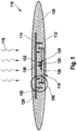
- FIG. 1 an exemplary embodiment of an eyepiece sensor 110 according to the invention is shown in highly schematic form.
- the eyepiece sensor is designed in this case, for example, as an implant and can be implanted, for example, in or under a conjunctiva of a patient.
- the eyepiece sensor 110 has an eye side 112 and an outside 114. Accordingly, daylight 116 can impinge on the eyepiece sensor 110 from the outside 114.
- the eyepiece sensor 110 has a sensor chip 118, which, as described above, is preferably designed as an ASIC.
- This sensor chip 118 is embedded in a biocompatible hydrogel as carrier material 120.
- This carrier material thus gives the eyepiece sensor 110 the required mechanical stability, but at the same time is deformable or flexible in order to adapt to the eye and enables a diffusion of the analyte.
- a sensor material is mixed in this embodiment.
- this sensor material may be sensor materials for the detection of glucose in an ocular fluid, for example in tears, aqueous humor or interstitial ocular fluid.
- sensor materials are in WO 01/13783 A1 .
- the following sensor materials are used: concanavalin A / dextran, glucose-galactose binding protein (GGBP), glucose hexokinase boric acid esters (such as in PCT / EP2004 / 008825 described).
- GGBP glucose-galactose binding protein
- GGBP glucose hexokinase boric acid esters
- other sensor materials are used, as well as mixtures or combinations of several sensor materials.
- This sensor material may be homogeneously distributed directly in the hydrogel, but may also be enclosed in microcapsules, which in turn are preferably distributed in the hydrogel.
- such an implanted ocular sensor 110 such as in WO 01/13783 A1 described from the outside, that is from the outside 114, with a suitable light source (for example, a light emitting diode with a bandpass filter and / or a laser diode) excited to fluoresce and the fluorescence measured at one or more wavelengths with a suitable photometer.
- a suitable light source for example, a light emitting diode with a bandpass filter and / or a laser diode
- the intensity of the fluorescence signal is naturally not only dependent on the analyte concentration, but also on the distance and angle between implant and photometer and / or excitation light source.
- the present eyepiece sensor 110 solves this problem as described above by including the sensor chip 118 as an integral part.
- This sensor chip 118 which is preferably configured as an ASIC, can be manufactured, for example, customized and, for example, based on an organic or inorganic semiconductor material, for example Silicon.
- at least part of an evaluation and control electronics can be integrated on the sensor chip 118.
- the sensor chip 118 comprises three photodiodes: In addition to the actual measuring diode 122 as an optical detector, a reference diode 124 and a background diode 126 are integrated on the sensor chip 118. The required drive or evaluation circuits are also integrated on the sensor chip 118, but are in FIG. 1 not shown.
- a reference material is further mixed into the carrier material 120, for example a reference fluorophore whose luminescence can likewise be excited by the daylight 116, but this reference fluorescence is independent of the presence of the analyte to be detected.
- the sensor chip 118 is first covered with a background filter 128.
- This background filter 128 is configured as an interference filter in this embodiment.
- the measuring diode 122 is covered with a sensor filter 130, and the reference diode 124 with a reference filter 132.
- sensor filter 130 and reference filter 132 are preferably designed as interference filter.
- the background diode 126 is not further equipped with a filter (except by the background filter 128). For the transmission characteristics of these filters 128, 130 and 132, reference is made to FIG. 2 , In FIG.
- the filters 128 and 130 are configured as bandpass filters, with a transmission of approx 560 to 600 nm or approximately 620 to 670 nm.
- the reference filter 132 is configured substantially as an edge filter and "opens" at a wavelength of approximately 740 nm.
- the three filters 128, 130 and 132 are designed in their spectral properties such that the filter 128 has a transmission in the region of the excitation wavelength of the sensor material.
- the filters 130 and 132 have a transmission in the region of the luminescence wavelength of the sensor material (sensor filter 130) or in the region of the fluorescence of the reference material (reference filter 132).
- the eyepiece sensor 110 embodied as an implant is inventively implanted under the conjunctiva of the eye, where it is exposed to the normal daylight 116. Because the conjunctiva is profound is transparent, penetrates, in contrast to normal pigmented skin, a comparatively high proportion of light in the implant formed as eyepiece sensor 110 a.
- the spectral light conditions (plotted is the intensity I against the wavelength ⁇ ) are plotted in the eyepiece sensor 110.
- the curve 140 shows the intensity distribution of the daylight 116.
- the sensor chip 118 from the background filter 128 (compare the transmission characteristic 134 in FIG. 2 ) is completely surrounded, penetrates from the daylight 116 only the portion required for the excitation of the sensor material.
- the spectral intensity distribution of this actual excitation light is in FIG. 3 indicated by the curve 142 and results from a multiplication of the curve 134 in FIG. 2 with the intensity distribution of daylight 140 in FIG. 3 ,
- This intensity 142 of the excitation light is mixed with the background diode 126 (see FIG. 1 ) is measured on the sensor chip 118.
- the measuring diode 122 with the sensor filter 130 and the reference diode 124 with the reference filter 132 used. Accordingly, the total fluorescence is 144 in FIG. 3 again with the transmission curves 136 and 138, respectively FIG. 2 to multiply. This filtering thus leads to a sensor fluorescence 146, which is detected by the measuring diode 122, as well as to a reference fluorescence 148, which is detected by the reference diode 124.
- the background diode 146 provides information about how strongly the sensor material and the reference material are excited
- the measuring diode 122 provides information about the analyte-dependent sensor fluorescence of the sensor material
- the reference diode 124 provides analyte-independent information about the reference fluorescence of the reference material. From these three signal components can be deduced with great accuracy to a concentration of the analyte in the eye fluid.
- the measurement signal or the measurement signals is no longer position-dependent.
- the measurement signal is thus in the ideal case only dependent on the excitation energy (this information is provided by the background diode 126) and the analyte concentration.
- the concurrent provision of background diode 126 information and the reference diode 124 is somewhat redundant, but the additional information increases the robustness and measurement accuracy of the system.
- changes in the spectral characteristic of this excitation light can be compensated, such as the change from daylight to artificial ambient light. In this way, the flexibility of the application is significantly increased, so that measurements of the analyte concentration at different times of day and / or changing the lighting conditions (daylight, artificial light) can be made.
- the arrangement of the eyepiece sensor 110 according to FIG. 1 has another feature in the form of a light trap 150.
- This light trap 150 takes into account the idea that, on the one hand, the three photodiodes 122, 124 and 126 on the sensor chip 118 should be completely surrounded by the background filter 128, since otherwise incoming daylight 116 would lead to an offset, which would generally be considerably greater than that actual measurement signal.
- the sensor material should be accommodated and free diffusion of the analyte should be possible. This problem is solved in the illustrated embodiment by the light trap 150, which allows diffusion of the analyte in the substrate 120, but suppresses penetration of unfiltered daylight 116.
- Mechanical light traps 150 are typically as in FIG FIG. 1 shown realized by a plurality of, undercutting webs 152.
- Other types of light traps 150 such as optical "mazes", as they are known for example from the art of smoke detectors, can be used.
- a further possibility, which can be used alternatively or in addition, is to mark the hydrogel of the carrier material 120 itself with corresponding dye molecules, so that the background filter 128 is configured not in the form of an interference filter but in the form of a bulk filter. In this way too, the transmission 134 can be approximately realized.
- filter characteristics of such dye molecules are typically wider than the filter characteristic of curve 134 in FIG. 2 .
- the advantage of an interference filter is that the spectral characteristic can be influenced comparatively easily.
- Interference filters could be made, for example, by depositing a thin metal and / or metal compound layer sequence on a transparent support, such as a thin glass and / or a plastic material, which is subsequently exposed as shown in FIG FIG.
- FIG. 4 is a highly schematic representation of a way to read the sensor chip 118.
- the sensor chip 118 which in this case in FIG. 4 is reproduced only incompletely, acts together with an excitation unit 154, which in an evaluation (compare FIG. 5 ) is implemented.
- the capacitive element 156 of the sensor chip 118 is connected to ground via an ohmic resistor 160 (for example, a larger metal surface on the sensor chip 118).
- Parallel to the resistor 160 is or are the diodes 122, 124 and 126 connected.
- the circuit can be made such that these diodes individually or all in the in FIG. 4 shown switched manner.
- the capacitive element 158 is connected via a resistor 162 to a generator 164, which in turn is connected to ground at its other terminal.
- the excitation unit 154 and the sensor chip 118 form an excited electrical resonant circuit in this circuit.
- the generator 164 generates a varying electric field across the capacitive elements 156, 158.
- the natural frequency of the resonant circuit is determined by the capacitances (determined by the interaction of the capacitive elements 156, 158) and the resistors 160, 162 in the resonant circuit.
- the excitation unit 154 may accordingly comprise a field needle and a field strength measuring device to measure these field strength changes. Alternatively or additionally, however, other measurement techniques may also be used, such as, for example, a measurement of the power output of the generator 164.
- FIG. 5 is shown in highly schematic form a measuring system 166 for detecting the at least one analyte in an ocular fluid.
- the measuring system 166 comprises an eyepiece sensor 110, for example an eyepiece sensor according to the in FIG. 1 described embodiment, which may be configured for example as an implant and / or as an eye lens.
- the measuring system 166 comprises an evaluation unit 168 with an excitation unit 154 (for example according to the exemplary embodiment in FIG FIG. 4 ) and a microcomputer 170.
- the evaluation unit 168 for example, on the basis of FIG. 4 described process exchange information with the eyepiece 110 and the sensor chip 118 and thus "in situ" (that is, without having to remove the ocular sensor 110 from the eye fluid) query measurement data.
- the evaluation unit 168 can be worn anywhere on the body of the patient. The body can then serve as part of the interface in addition to the capacitive elements 156, 158 according to FIG FIG. 4 , and contributes to data transmission.
- the microcomputer 170 of the evaluation unit 168 is preferably designed according to the above description and serves to control the measurement and to evaluate the measurement results.
- the microcomputer 170 can be operated by controls 172 by a user, and information can be output to a user via a display 174.
- controls 172 by a user can be operated by controls 172 by a user, and information can be output to a user via a display 174.
- other user interfaces are also implementable.
- the measuring system 166 according to the exemplary embodiment in FIG. 5 a calibration system 176.
- This calibration system 176 is preferably implemented in the evaluation unit 168.
- the calibration unit 176 is designed as a separate unit which communicates via an interface 178 with the evaluation unit 168. This may be a wireless and / or a wired interface, or it may also be provided via data exchange devices manually exchanged by the patient between the calibration system 176 and the evaluation unit 168 data carriers (eg memory chips) as "interfaces" for connecting these elements.
- data carriers eg memory chips
- the calibration system 176 again comprises controls 180, a display 182 and (in FIG. 5 not shown) corresponding electronics, for example, in turn, a microcomputer and / or other electronic components.
- the calibration system 176 is configured to detect by means of a test strip 184 a concentration of the analyte in a body fluid, which is shown here symbolically as a blood drop 186.
- a concentration of the analyte in a body fluid which is shown here symbolically as a blood drop 186.
- 176 conventional, commercially available measuring devices, such as blood glucose meters, can be used as the calibration system.
- Such systems usually also have corresponding interfaces, such as infrared interfaces.
- the information about the analyte concentration in the body fluid, for example the blood glucose concentration, obtained by means of the calibration system 176 can be communicated to the evaluation unit 168 via the interface 178 in order to be used there for comparison with the information of the sensor chip 118 of the eyepiece sensor 110.
- the measurement of blood glucose measurement may be introduced directly into the algorithm of indirect blood glucose determination with the ocular sensor 110.
Landscapes
- Health & Medical Sciences (AREA)
- Life Sciences & Earth Sciences (AREA)
- Physics & Mathematics (AREA)
- Public Health (AREA)
- General Health & Medical Sciences (AREA)
- Biophysics (AREA)
- Veterinary Medicine (AREA)
- Engineering & Computer Science (AREA)
- Biomedical Technology (AREA)
- Heart & Thoracic Surgery (AREA)
- Medical Informatics (AREA)
- Molecular Biology (AREA)
- Surgery (AREA)
- Animal Behavior & Ethology (AREA)
- Pathology (AREA)
- Optics & Photonics (AREA)
- Emergency Medicine (AREA)
- Spectroscopy & Molecular Physics (AREA)
- Ophthalmology & Optometry (AREA)
- Hematology (AREA)
- Investigating, Analyzing Materials By Fluorescence Or Luminescence (AREA)
- Measurement Of The Respiration, Hearing Ability, Form, And Blood Characteristics Of Living Organisms (AREA)
- Investigating Or Analysing Biological Materials (AREA)
- Investigating Or Analysing Materials By The Use Of Chemical Reactions (AREA)
- Measuring And Recording Apparatus For Diagnosis (AREA)
Applications Claiming Priority (2)
| Application Number | Priority Date | Filing Date | Title |
|---|---|---|---|
| DE102007003341.0A DE102007003341B4 (de) | 2007-01-17 | 2007-01-17 | Okularsensor und Messsystem zum Nachweis eines Analyten in einer Augenflüssigkeit |
| PCT/EP2008/050347 WO2008087118A1 (de) | 2007-01-17 | 2008-01-14 | Okularsensor zum nachweis eines analyten in einer augenflüssigkeit |
Publications (2)
| Publication Number | Publication Date |
|---|---|
| EP2109393A1 EP2109393A1 (de) | 2009-10-21 |
| EP2109393B1 true EP2109393B1 (de) | 2018-08-08 |
Family
ID=39464489
Family Applications (1)
| Application Number | Title | Priority Date | Filing Date |
|---|---|---|---|
| EP08701462.7A Not-in-force EP2109393B1 (de) | 2007-01-17 | 2008-01-14 | Okularsensor zum nachweis eines analyten in einer augenflüssigkeit |
Country Status (13)
| Country | Link |
|---|---|
| US (1) | US8452361B2 (xx) |
| EP (1) | EP2109393B1 (xx) |
| JP (1) | JP5390399B2 (xx) |
| KR (1) | KR20090104865A (xx) |
| CN (1) | CN101621961B (xx) |
| AU (1) | AU2008207041B2 (xx) |
| BR (1) | BRPI0806777A2 (xx) |
| CA (1) | CA2675609C (xx) |
| DE (1) | DE102007003341B4 (xx) |
| ES (1) | ES2694019T3 (xx) |
| HK (1) | HK1139849A1 (xx) |
| MX (1) | MX2009007684A (xx) |
| WO (1) | WO2008087118A1 (xx) |
Families Citing this family (67)
| Publication number | Priority date | Publication date | Assignee | Title |
|---|---|---|---|---|
| DE102007024642A1 (de) * | 2007-05-24 | 2008-11-27 | Eyesense Ag | Hydrogel-Implantat für Sensorik von Metaboliten am Auge |
| US9517023B2 (en) | 2009-06-01 | 2016-12-13 | Profusa, Inc. | Method and system for directing a localized biological response to an implant |
| US8452362B2 (en) * | 2010-01-26 | 2013-05-28 | Chromologic Llc | Method and system for monitoring hydration |
| US10010272B2 (en) | 2010-05-27 | 2018-07-03 | Profusa, Inc. | Tissue-integrating electronic apparatus |
| JP5827999B2 (ja) | 2010-10-06 | 2015-12-02 | プロフューザ,インコーポレイティド | 組織集積センサー |
| JP2012233888A (ja) * | 2011-04-21 | 2012-11-29 | Universal Bio Research Co Ltd | 複数種の目的物質を同時に検出又は定量するための分析方法 |
| US8888973B2 (en) * | 2011-07-29 | 2014-11-18 | Roche Diagnostics Operations, Inc. | Encoded biosensors and methods of manufacture and use thereof |
| EP2755549A1 (en) * | 2011-09-13 | 2014-07-23 | Dose Medical Corporation | Intraocular physiological sensor |
| US8798332B2 (en) | 2012-05-15 | 2014-08-05 | Google Inc. | Contact lenses |
| US9523865B2 (en) | 2012-07-26 | 2016-12-20 | Verily Life Sciences Llc | Contact lenses with hybrid power sources |
| US9298020B1 (en) | 2012-07-26 | 2016-03-29 | Verily Life Sciences Llc | Input system |
| US8857981B2 (en) | 2012-07-26 | 2014-10-14 | Google Inc. | Facilitation of contact lenses with capacitive sensors |
| US9158133B1 (en) | 2012-07-26 | 2015-10-13 | Google Inc. | Contact lens employing optical signals for power and/or communication |
| US8919953B1 (en) | 2012-08-02 | 2014-12-30 | Google Inc. | Actuatable contact lenses |
| US9696564B1 (en) | 2012-08-21 | 2017-07-04 | Verily Life Sciences Llc | Contact lens with metal portion and polymer layer having indentations |
| US8971978B2 (en) | 2012-08-21 | 2015-03-03 | Google Inc. | Contact lens with integrated pulse oximeter |
| US9111473B1 (en) | 2012-08-24 | 2015-08-18 | Google Inc. | Input system |
| US8820934B1 (en) | 2012-09-05 | 2014-09-02 | Google Inc. | Passive surface acoustic wave communication |
| US20140192315A1 (en) | 2012-09-07 | 2014-07-10 | Google Inc. | In-situ tear sample collection and testing using a contact lens |
| US9398868B1 (en) | 2012-09-11 | 2016-07-26 | Verily Life Sciences Llc | Cancellation of a baseline current signal via current subtraction within a linear relaxation oscillator-based current-to-frequency converter circuit |
| US10010270B2 (en) | 2012-09-17 | 2018-07-03 | Verily Life Sciences Llc | Sensing system |
| US9326710B1 (en) | 2012-09-20 | 2016-05-03 | Verily Life Sciences Llc | Contact lenses having sensors with adjustable sensitivity |
| US8960898B1 (en) | 2012-09-24 | 2015-02-24 | Google Inc. | Contact lens that restricts incoming light to the eye |
| US8870370B1 (en) | 2012-09-24 | 2014-10-28 | Google Inc. | Contact lens that facilitates antenna communication via sensor impedance modulation |
| US20140088372A1 (en) * | 2012-09-25 | 2014-03-27 | Google Inc. | Information processing method |
| US8979271B2 (en) | 2012-09-25 | 2015-03-17 | Google Inc. | Facilitation of temperature compensation for contact lens sensors and temperature sensing |
| US20140085601A1 (en) * | 2012-09-25 | 2014-03-27 | Google Inc. | Contact lens having a chip integrated into a polymer substrate and method of manufacture |
| US8989834B2 (en) * | 2012-09-25 | 2015-03-24 | Google Inc. | Wearable device |
| US8985763B1 (en) | 2012-09-26 | 2015-03-24 | Google Inc. | Contact lens having an uneven embedded substrate and method of manufacture |
| US8960899B2 (en) | 2012-09-26 | 2015-02-24 | Google Inc. | Assembling thin silicon chips on a contact lens |
| US8821811B2 (en) | 2012-09-26 | 2014-09-02 | Google Inc. | In-vitro contact lens testing |
| US9884180B1 (en) | 2012-09-26 | 2018-02-06 | Verily Life Sciences Llc | Power transducer for a retinal implant using a contact lens |
| US9063351B1 (en) | 2012-09-28 | 2015-06-23 | Google Inc. | Input detection system |
| US8965478B2 (en) | 2012-10-12 | 2015-02-24 | Google Inc. | Microelectrodes in an ophthalmic electrochemical sensor |
| US9176332B1 (en) | 2012-10-24 | 2015-11-03 | Google Inc. | Contact lens and method of manufacture to improve sensor sensitivity |
| US9757056B1 (en) | 2012-10-26 | 2017-09-12 | Verily Life Sciences Llc | Over-molding of sensor apparatus in eye-mountable device |
| US8874182B2 (en) | 2013-01-15 | 2014-10-28 | Google Inc. | Encapsulated electronics |
| US9289954B2 (en) | 2013-01-17 | 2016-03-22 | Verily Life Sciences Llc | Method of ring-shaped structure placement in an eye-mountable device |
| US20140209481A1 (en) | 2013-01-25 | 2014-07-31 | Google Inc. | Standby Biasing Of Electrochemical Sensor To Reduce Sensor Stabilization Time During Measurement |
| US9636016B1 (en) | 2013-01-25 | 2017-05-02 | Verily Life Sciences Llc | Eye-mountable devices and methods for accurately placing a flexible ring containing electronics in eye-mountable devices |
| BR112015018811A2 (pt) | 2013-02-06 | 2017-07-18 | California Inst Of Techn | dispositivos sensores eletroquímicos miniaturizados implantáveis |
| EP3763292A1 (en) | 2013-03-14 | 2021-01-13 | Profusa, Inc. | Method and device for correcting optical signals |
| US9977260B2 (en) * | 2013-03-15 | 2018-05-22 | Johnson & Johnson Vision Care, Inc. | Sealing and encapsulation in energized ophthalmic devices with annular inserts |
| US9161712B2 (en) | 2013-03-26 | 2015-10-20 | Google Inc. | Systems and methods for encapsulating electronics in a mountable device |
| US9113829B2 (en) * | 2013-03-27 | 2015-08-25 | Google Inc. | Systems and methods for encapsulating electronics in a mountable device |
| WO2014197786A2 (en) | 2013-06-06 | 2014-12-11 | Kintz Gregory J | Apparatus and methods for detecting optical signals from implanted sensors |
| US20140371560A1 (en) | 2013-06-14 | 2014-12-18 | Google Inc. | Body-Mountable Devices and Methods for Embedding a Structure in a Body-Mountable Device |
| US9084561B2 (en) | 2013-06-17 | 2015-07-21 | Google Inc. | Symmetrically arranged sensor electrodes in an ophthalmic electrochemical sensor |
| US9948895B1 (en) | 2013-06-18 | 2018-04-17 | Verily Life Sciences Llc | Fully integrated pinhole camera for eye-mountable imaging system |
| US9685689B1 (en) | 2013-06-27 | 2017-06-20 | Verily Life Sciences Llc | Fabrication methods for bio-compatible devices |
| US9814387B2 (en) | 2013-06-28 | 2017-11-14 | Verily Life Sciences, LLC | Device identification |
| US9028772B2 (en) | 2013-06-28 | 2015-05-12 | Google Inc. | Methods for forming a channel through a polymer layer using one or more photoresist layers |
| US8922366B1 (en) * | 2013-06-28 | 2014-12-30 | Google Inc. | Reader communication with contact lens sensors and display device |
| US9492118B1 (en) | 2013-06-28 | 2016-11-15 | Life Sciences Llc | Pre-treatment process for electrochemical amperometric sensor |
| US9307901B1 (en) | 2013-06-28 | 2016-04-12 | Verily Life Sciences Llc | Methods for leaving a channel in a polymer layer using a cross-linked polymer plug |
| US9452260B2 (en) | 2013-11-22 | 2016-09-27 | Verily Life Sciences Llc | Closed loop control system based on a non-invasive continuous sensor |
| US9572522B2 (en) | 2013-12-20 | 2017-02-21 | Verily Life Sciences Llc | Tear fluid conductivity sensor |
| US9654674B1 (en) | 2013-12-20 | 2017-05-16 | Verily Life Sciences Llc | Image sensor with a plurality of light channels |
| US9366570B1 (en) | 2014-03-10 | 2016-06-14 | Verily Life Sciences Llc | Photodiode operable in photoconductive mode and photovoltaic mode |
| US9184698B1 (en) | 2014-03-11 | 2015-11-10 | Google Inc. | Reference frequency from ambient light signal |
| US9789655B1 (en) | 2014-03-14 | 2017-10-17 | Verily Life Sciences Llc | Methods for mold release of body-mountable devices including microelectronics |
| EP3131454A4 (en) * | 2014-04-15 | 2018-01-03 | Gandhi, Harry | Functional contact lens and related systems and methods |
| US10820844B2 (en) | 2015-07-23 | 2020-11-03 | California Institute Of Technology | Canary on a chip: embedded sensors with bio-chemical interfaces |
| WO2018119400A1 (en) | 2016-12-22 | 2018-06-28 | Profusa, Inc. | System and single-channel luminescent sensor for and method of determining analyte value |
| WO2019177540A1 (en) * | 2018-03-14 | 2019-09-19 | Menicon Singapore Pte Ltd. | Wearable device for communication with an ophthalmic device |
| KR102235213B1 (ko) * | 2018-12-06 | 2021-04-02 | 단국대학교 산학협력단 | Poss를 포함하는 콘택트렌즈 |
| DE102019203016A1 (de) * | 2019-03-06 | 2020-09-10 | Robert Bosch Gmbh | Sensoranordnung zur Bestimmung mindestens eines Drucks eines fluiden oder gasförmigen Mediums |
Citations (1)
| Publication number | Priority date | Publication date | Assignee | Title |
|---|---|---|---|---|
| US20020099359A1 (en) * | 2001-01-09 | 2002-07-25 | Santini John T. | Flexible microchip devices for ophthalmic and other applications |
Family Cites Families (20)
| Publication number | Priority date | Publication date | Assignee | Title |
|---|---|---|---|---|
| US3958560A (en) * | 1974-11-25 | 1976-05-25 | Wayne Front March | Non-invasive automatic glucose sensor system |
| JPH0593723A (ja) * | 1991-04-26 | 1993-04-16 | Nippondenso Co Ltd | 涙液物質の測定装置 |
| US5553617A (en) * | 1995-01-20 | 1996-09-10 | Hughes Aircraft Company | Noninvasive method and apparatus for determining body chemistry |
| US6120460A (en) | 1996-09-04 | 2000-09-19 | Abreu; Marcio Marc | Method and apparatus for signal acquisition, processing and transmission for evaluation of bodily functions |
| US5830139A (en) | 1996-09-04 | 1998-11-03 | Abreu; Marcio M. | Tonometer system for measuring intraocular pressure by applanation and/or indentation |
| US6579690B1 (en) * | 1997-12-05 | 2003-06-17 | Therasense, Inc. | Blood analyte monitoring through subcutaneous measurement |
| US6558320B1 (en) | 2000-01-20 | 2003-05-06 | Medtronic Minimed, Inc. | Handheld personal data assistant (PDA) with a medical device and method of using the same |
| AU2004201752B2 (en) * | 1998-08-26 | 2007-01-11 | Sensors For Medicine And Science, Inc. | Optical-based sensing devices |
| ATE394662T1 (de) * | 1998-08-26 | 2008-05-15 | Sensors For Med & Science Inc | Optisch basierte sensor-vorrichtungen |
| JP2002536103A (ja) * | 1999-02-12 | 2002-10-29 | シグナス, インコーポレイテッド | 生物学的系に存在する分析物の頻繁な測定のためのデバイスおよび方法 |
| EP1057730A1 (de) * | 1999-05-04 | 2000-12-06 | Novartis AG | Verfahren und Vorrichtung zum Erfassen von ophthalmischen Formkörpern in einer Verpackung |
| CN1196436C (zh) * | 1999-08-26 | 2005-04-13 | 诺瓦提斯公司 | 眼分析物传感器 |
| US7553280B2 (en) * | 2000-06-29 | 2009-06-30 | Sensors For Medicine And Science, Inc. | Implanted sensor processing system and method |
| US6400974B1 (en) * | 2000-06-29 | 2002-06-04 | Sensors For Medicine And Science, Inc. | Implanted sensor processing system and method for processing implanted sensor output |
| CA2441787C (en) | 2001-04-27 | 2011-08-09 | Novartis Ag | Apparatus for measuring blood glucose concentrations |
| EP1589866A2 (en) * | 2003-01-09 | 2005-11-02 | The Regents of the University of California | Implantable devices and methods for measuring intraocular, subconjunctival or subdermal pressure and/or analyte concentration |
| DE602004007771T2 (de) | 2003-02-14 | 2007-12-06 | Eyesense Ag | Vorrichtung zur messung der konzentration eines analyten in einer augenflüssigkeit |
| DE602004028020D1 (de) | 2003-08-07 | 2010-08-19 | Eyesense Ag | Ophthalmischer sensor |
| WO2005051170A2 (en) * | 2003-11-19 | 2005-06-09 | Dexcom, Inc. | Integrated receiver for continuous analyte sensor |
| JP4455216B2 (ja) * | 2004-08-06 | 2010-04-21 | キヤノン株式会社 | 検出装置 |
-
2007
- 2007-01-17 DE DE102007003341.0A patent/DE102007003341B4/de not_active Expired - Fee Related
-
2008
- 2008-01-14 AU AU2008207041A patent/AU2008207041B2/en not_active Ceased
- 2008-01-14 EP EP08701462.7A patent/EP2109393B1/de not_active Not-in-force
- 2008-01-14 ES ES08701462.7T patent/ES2694019T3/es active Active
- 2008-01-14 CN CN2008800066980A patent/CN101621961B/zh not_active Expired - Fee Related
- 2008-01-14 MX MX2009007684A patent/MX2009007684A/es active IP Right Grant
- 2008-01-14 WO PCT/EP2008/050347 patent/WO2008087118A1/de active Application Filing
- 2008-01-14 BR BRPI0806777-5A patent/BRPI0806777A2/pt not_active IP Right Cessation
- 2008-01-14 CA CA2675609A patent/CA2675609C/en not_active Expired - Fee Related
- 2008-01-14 US US12/523,434 patent/US8452361B2/en active Active
- 2008-01-14 KR KR1020097017010A patent/KR20090104865A/ko not_active Application Discontinuation
- 2008-01-14 JP JP2009545901A patent/JP5390399B2/ja active Active
-
2010
- 2010-06-15 HK HK10105978.3A patent/HK1139849A1/xx not_active IP Right Cessation
Patent Citations (1)
| Publication number | Priority date | Publication date | Assignee | Title |
|---|---|---|---|---|
| US20020099359A1 (en) * | 2001-01-09 | 2002-07-25 | Santini John T. | Flexible microchip devices for ophthalmic and other applications |
Also Published As
| Publication number | Publication date |
|---|---|
| ES2694019T3 (es) | 2018-12-17 |
| JP5390399B2 (ja) | 2014-01-15 |
| WO2008087118A1 (de) | 2008-07-24 |
| HK1139849A1 (en) | 2010-09-30 |
| JP2010516312A (ja) | 2010-05-20 |
| MX2009007684A (es) | 2009-12-15 |
| DE102007003341A1 (de) | 2008-07-31 |
| DE102007003341B4 (de) | 2018-01-04 |
| CA2675609A1 (en) | 2008-07-24 |
| US8452361B2 (en) | 2013-05-28 |
| US20100249548A1 (en) | 2010-09-30 |
| AU2008207041B2 (en) | 2012-11-29 |
| EP2109393A1 (de) | 2009-10-21 |
| CA2675609C (en) | 2016-06-28 |
| BRPI0806777A2 (pt) | 2011-09-13 |
| CN101621961A (zh) | 2010-01-06 |
| AU2008207041A1 (en) | 2008-07-24 |
| KR20090104865A (ko) | 2009-10-06 |
| CN101621961B (zh) | 2012-05-09 |
Similar Documents
| Publication | Publication Date | Title |
|---|---|---|
| EP2109393B1 (de) | Okularsensor zum nachweis eines analyten in einer augenflüssigkeit | |
| DE10011284B4 (de) | Vorrichtung für eine In-vivo Messung der Konzentration eines Inhaltsstoffs einer Körperflüssigkeit | |
| EP1882446B1 (de) | Vorrichtung zur Messung eines Analyten in einer Augenflüssigkeit | |
| DE60119556T2 (de) | Optischer sensor zur in-situ messung von analyten | |
| DE60133653T2 (de) | Vorrichtung zum vorhersagen von hypoglyecemiefällen | |
| DE60035174T2 (de) | Invasives verfahren zur in vivo analytvermessung | |
| EP2317911B1 (de) | Transkutane organfunktionsmessung | |
| DE102012201892A1 (de) | Bestimmung des Blutzuckerspiegels eines Patienten unter Verwendung eines implantierbaren Sensors und eines elektrischen Funktionspflasters | |
| EP1800122A1 (de) | Analytisches testelement mit drahtloser datenübertragung | |
| EP0707826A1 (de) | Verfahren und Vorrichtung zur Analyse von Glukose in einer biologischen Matrix | |
| EP1292220A1 (de) | Verfahren und vorrichtung zum nachweisen von substanzen in körperflüssigkeiten mittels raman-spektroskopie | |
| WO2007115732A1 (de) | Analyse optischer daten mit hilfe von histogrammen | |
| EP2794909B1 (de) | Verfahren zur bestimmung einer analytkonzentration | |
| WO2001028414A2 (de) | Vorrichtung zur noninvasiven bestimmung der konzentration von bestandteilen im blut | |
| EP2786121B1 (de) | Messkammer für einen optischen sensor zum bestimmen einer konzentration eines stoffes in der gewebeflüssigkeit eines säugers | |
| DE69824831T2 (de) | Sensor unter verwendung von lebenden muskelzellen | |
| EP3990895A1 (de) | Sensormodul zur multiparametrischen analyse eines mediums | |
| EP1273904A2 (de) | Verfahren und Vorrichtung zur Erfassung von Stoffen in vitalem Gewebe | |
| EP0984718B1 (de) | Messgerät zur Ermittlung des Konzentrationsgehaltes von in Flüssigkeit enthaltenen Substanzen mittels einem ATR Element. | |
| DE69736556T2 (de) | Implantierbarer sensor sowie anordnung zum in-vivo messen und steuern von konzentrationen in flüssigkeiten und gasen |
Legal Events
| Date | Code | Title | Description |
|---|---|---|---|
| PUAI | Public reference made under article 153(3) epc to a published international application that has entered the european phase |
Free format text: ORIGINAL CODE: 0009012 |
|
| 17P | Request for examination filed |
Effective date: 20090817 |
|
| AK | Designated contracting states |
Kind code of ref document: A1 Designated state(s): AT BE BG CH CY CZ DE DK EE ES FI FR GB GR HR HU IE IS IT LI LT LU LV MC MT NL NO PL PT RO SE SI SK TR |
|
| DAX | Request for extension of the european patent (deleted) | ||
| 17Q | First examination report despatched |
Effective date: 20130403 |
|
| REG | Reference to a national code |
Ref country code: DE Ref legal event code: R079 Ref document number: 502008016244 Country of ref document: DE Free format text: PREVIOUS MAIN CLASS: A61B0005000000 Ipc: A61B0005145000 |
|
| RIC1 | Information provided on ipc code assigned before grant |
Ipc: A61B 5/1459 20060101ALN20180322BHEP Ipc: A61B 5/1455 20060101ALI20180322BHEP Ipc: A61B 5/145 20060101AFI20180322BHEP |
|
| GRAP | Despatch of communication of intention to grant a patent |
Free format text: ORIGINAL CODE: EPIDOSNIGR1 |
|
| STAA | Information on the status of an ep patent application or granted ep patent |
Free format text: STATUS: GRANT OF PATENT IS INTENDED |
|
| INTG | Intention to grant announced |
Effective date: 20180430 |
|
| GRAS | Grant fee paid |
Free format text: ORIGINAL CODE: EPIDOSNIGR3 |
|
| GRAA | (expected) grant |
Free format text: ORIGINAL CODE: 0009210 |
|
| STAA | Information on the status of an ep patent application or granted ep patent |
Free format text: STATUS: THE PATENT HAS BEEN GRANTED |
|
| AK | Designated contracting states |
Kind code of ref document: B1 Designated state(s): AT BE BG CH CY CZ DE DK EE ES FI FR GB GR HR HU IE IS IT LI LT LU LV MC MT NL NO PL PT RO SE SI SK TR |
|
| REG | Reference to a national code |
Ref country code: GB Ref legal event code: FG4D Free format text: NOT ENGLISH |
|
| REG | Reference to a national code |
Ref country code: AT Ref legal event code: REF Ref document number: 1026053 Country of ref document: AT Kind code of ref document: T Effective date: 20180815 Ref country code: CH Ref legal event code: EP |
|
| REG | Reference to a national code |
Ref country code: IE Ref legal event code: FG4D Free format text: LANGUAGE OF EP DOCUMENT: GERMAN |
|
| REG | Reference to a national code |
Ref country code: DE Ref legal event code: R096 Ref document number: 502008016244 Country of ref document: DE |
|
| REG | Reference to a national code |
Ref country code: NL Ref legal event code: MP Effective date: 20180808 |
|
| REG | Reference to a national code |
Ref country code: ES Ref legal event code: FG2A Ref document number: 2694019 Country of ref document: ES Kind code of ref document: T3 Effective date: 20181217 |
|
| REG | Reference to a national code |
Ref country code: LT Ref legal event code: MG4D |
|
| PG25 | Lapsed in a contracting state [announced via postgrant information from national office to epo] |
Ref country code: FI Free format text: LAPSE BECAUSE OF FAILURE TO SUBMIT A TRANSLATION OF THE DESCRIPTION OR TO PAY THE FEE WITHIN THE PRESCRIBED TIME-LIMIT Effective date: 20180808 Ref country code: GR Free format text: LAPSE BECAUSE OF FAILURE TO SUBMIT A TRANSLATION OF THE DESCRIPTION OR TO PAY THE FEE WITHIN THE PRESCRIBED TIME-LIMIT Effective date: 20181109 Ref country code: NO Free format text: LAPSE BECAUSE OF FAILURE TO SUBMIT A TRANSLATION OF THE DESCRIPTION OR TO PAY THE FEE WITHIN THE PRESCRIBED TIME-LIMIT Effective date: 20181108 Ref country code: LT Free format text: LAPSE BECAUSE OF FAILURE TO SUBMIT A TRANSLATION OF THE DESCRIPTION OR TO PAY THE FEE WITHIN THE PRESCRIBED TIME-LIMIT Effective date: 20180808 Ref country code: PL Free format text: LAPSE BECAUSE OF FAILURE TO SUBMIT A TRANSLATION OF THE DESCRIPTION OR TO PAY THE FEE WITHIN THE PRESCRIBED TIME-LIMIT Effective date: 20180808 Ref country code: IS Free format text: LAPSE BECAUSE OF FAILURE TO SUBMIT A TRANSLATION OF THE DESCRIPTION OR TO PAY THE FEE WITHIN THE PRESCRIBED TIME-LIMIT Effective date: 20181208 Ref country code: BG Free format text: LAPSE BECAUSE OF FAILURE TO SUBMIT A TRANSLATION OF THE DESCRIPTION OR TO PAY THE FEE WITHIN THE PRESCRIBED TIME-LIMIT Effective date: 20181108 Ref country code: SE Free format text: LAPSE BECAUSE OF FAILURE TO SUBMIT A TRANSLATION OF THE DESCRIPTION OR TO PAY THE FEE WITHIN THE PRESCRIBED TIME-LIMIT Effective date: 20180808 Ref country code: NL Free format text: LAPSE BECAUSE OF FAILURE TO SUBMIT A TRANSLATION OF THE DESCRIPTION OR TO PAY THE FEE WITHIN THE PRESCRIBED TIME-LIMIT Effective date: 20180808 |
|
| PG25 | Lapsed in a contracting state [announced via postgrant information from national office to epo] |
Ref country code: HR Free format text: LAPSE BECAUSE OF FAILURE TO SUBMIT A TRANSLATION OF THE DESCRIPTION OR TO PAY THE FEE WITHIN THE PRESCRIBED TIME-LIMIT Effective date: 20180808 Ref country code: LV Free format text: LAPSE BECAUSE OF FAILURE TO SUBMIT A TRANSLATION OF THE DESCRIPTION OR TO PAY THE FEE WITHIN THE PRESCRIBED TIME-LIMIT Effective date: 20180808 |
|
| PG25 | Lapsed in a contracting state [announced via postgrant information from national office to epo] |
Ref country code: RO Free format text: LAPSE BECAUSE OF FAILURE TO SUBMIT A TRANSLATION OF THE DESCRIPTION OR TO PAY THE FEE WITHIN THE PRESCRIBED TIME-LIMIT Effective date: 20180808 Ref country code: CZ Free format text: LAPSE BECAUSE OF FAILURE TO SUBMIT A TRANSLATION OF THE DESCRIPTION OR TO PAY THE FEE WITHIN THE PRESCRIBED TIME-LIMIT Effective date: 20180808 Ref country code: EE Free format text: LAPSE BECAUSE OF FAILURE TO SUBMIT A TRANSLATION OF THE DESCRIPTION OR TO PAY THE FEE WITHIN THE PRESCRIBED TIME-LIMIT Effective date: 20180808 |
|
| REG | Reference to a national code |
Ref country code: DE Ref legal event code: R097 Ref document number: 502008016244 Country of ref document: DE |
|
| PG25 | Lapsed in a contracting state [announced via postgrant information from national office to epo] |
Ref country code: SK Free format text: LAPSE BECAUSE OF FAILURE TO SUBMIT A TRANSLATION OF THE DESCRIPTION OR TO PAY THE FEE WITHIN THE PRESCRIBED TIME-LIMIT Effective date: 20180808 Ref country code: DK Free format text: LAPSE BECAUSE OF FAILURE TO SUBMIT A TRANSLATION OF THE DESCRIPTION OR TO PAY THE FEE WITHIN THE PRESCRIBED TIME-LIMIT Effective date: 20180808 |
|
| PLBE | No opposition filed within time limit |
Free format text: ORIGINAL CODE: 0009261 |
|
| STAA | Information on the status of an ep patent application or granted ep patent |
Free format text: STATUS: NO OPPOSITION FILED WITHIN TIME LIMIT |
|
| 26N | No opposition filed |
Effective date: 20190509 |
|
| PG25 | Lapsed in a contracting state [announced via postgrant information from national office to epo] |
Ref country code: SI Free format text: LAPSE BECAUSE OF FAILURE TO SUBMIT A TRANSLATION OF THE DESCRIPTION OR TO PAY THE FEE WITHIN THE PRESCRIBED TIME-LIMIT Effective date: 20180808 Ref country code: MC Free format text: LAPSE BECAUSE OF FAILURE TO SUBMIT A TRANSLATION OF THE DESCRIPTION OR TO PAY THE FEE WITHIN THE PRESCRIBED TIME-LIMIT Effective date: 20180808 |
|
| REG | Reference to a national code |
Ref country code: CH Ref legal event code: PL |
|
| PG25 | Lapsed in a contracting state [announced via postgrant information from national office to epo] |
Ref country code: LU Free format text: LAPSE BECAUSE OF NON-PAYMENT OF DUE FEES Effective date: 20190114 |
|
| REG | Reference to a national code |
Ref country code: BE Ref legal event code: MM Effective date: 20190131 |
|
| REG | Reference to a national code |
Ref country code: IE Ref legal event code: MM4A |
|
| PG25 | Lapsed in a contracting state [announced via postgrant information from national office to epo] |
Ref country code: BE Free format text: LAPSE BECAUSE OF NON-PAYMENT OF DUE FEES Effective date: 20190131 |
|
| PG25 | Lapsed in a contracting state [announced via postgrant information from national office to epo] |
Ref country code: LI Free format text: LAPSE BECAUSE OF NON-PAYMENT OF DUE FEES Effective date: 20190131 Ref country code: CH Free format text: LAPSE BECAUSE OF NON-PAYMENT OF DUE FEES Effective date: 20190131 |
|
| PG25 | Lapsed in a contracting state [announced via postgrant information from national office to epo] |
Ref country code: IE Free format text: LAPSE BECAUSE OF NON-PAYMENT OF DUE FEES Effective date: 20190114 |
|
| REG | Reference to a national code |
Ref country code: AT Ref legal event code: MM01 Ref document number: 1026053 Country of ref document: AT Kind code of ref document: T Effective date: 20190114 |
|
| PG25 | Lapsed in a contracting state [announced via postgrant information from national office to epo] |
Ref country code: TR Free format text: LAPSE BECAUSE OF FAILURE TO SUBMIT A TRANSLATION OF THE DESCRIPTION OR TO PAY THE FEE WITHIN THE PRESCRIBED TIME-LIMIT Effective date: 20180808 |
|
| PG25 | Lapsed in a contracting state [announced via postgrant information from national office to epo] |
Ref country code: AT Free format text: LAPSE BECAUSE OF NON-PAYMENT OF DUE FEES Effective date: 20190114 |
|
| PGFP | Annual fee paid to national office [announced via postgrant information from national office to epo] |
Ref country code: DE Payment date: 20200123 Year of fee payment: 13 Ref country code: IT Payment date: 20200122 Year of fee payment: 13 Ref country code: GB Payment date: 20200127 Year of fee payment: 13 Ref country code: ES Payment date: 20200219 Year of fee payment: 13 |
|
| PG25 | Lapsed in a contracting state [announced via postgrant information from national office to epo] |
Ref country code: MT Free format text: LAPSE BECAUSE OF FAILURE TO SUBMIT A TRANSLATION OF THE DESCRIPTION OR TO PAY THE FEE WITHIN THE PRESCRIBED TIME-LIMIT Effective date: 20180808 Ref country code: PT Free format text: LAPSE BECAUSE OF FAILURE TO SUBMIT A TRANSLATION OF THE DESCRIPTION OR TO PAY THE FEE WITHIN THE PRESCRIBED TIME-LIMIT Effective date: 20181208 |
|
| PGFP | Annual fee paid to national office [announced via postgrant information from national office to epo] |
Ref country code: FR Payment date: 20200123 Year of fee payment: 13 |
|
| PG25 | Lapsed in a contracting state [announced via postgrant information from national office to epo] |
Ref country code: CY Free format text: LAPSE BECAUSE OF FAILURE TO SUBMIT A TRANSLATION OF THE DESCRIPTION OR TO PAY THE FEE WITHIN THE PRESCRIBED TIME-LIMIT Effective date: 20180808 |
|
| PG25 | Lapsed in a contracting state [announced via postgrant information from national office to epo] |
Ref country code: HU Free format text: LAPSE BECAUSE OF FAILURE TO SUBMIT A TRANSLATION OF THE DESCRIPTION OR TO PAY THE FEE WITHIN THE PRESCRIBED TIME-LIMIT; INVALID AB INITIO Effective date: 20080114 |
|
| REG | Reference to a national code |
Ref country code: DE Ref legal event code: R119 Ref document number: 502008016244 Country of ref document: DE |
|
| GBPC | Gb: european patent ceased through non-payment of renewal fee |
Effective date: 20210114 |
|
| PG25 | Lapsed in a contracting state [announced via postgrant information from national office to epo] |
Ref country code: FR Free format text: LAPSE BECAUSE OF NON-PAYMENT OF DUE FEES Effective date: 20210131 |
|
| PG25 | Lapsed in a contracting state [announced via postgrant information from national office to epo] |
Ref country code: GB Free format text: LAPSE BECAUSE OF NON-PAYMENT OF DUE FEES Effective date: 20210114 Ref country code: DE Free format text: LAPSE BECAUSE OF NON-PAYMENT OF DUE FEES Effective date: 20210803 |
|
| REG | Reference to a national code |
Ref country code: ES Ref legal event code: FD2A Effective date: 20220422 |
|
| PG25 | Lapsed in a contracting state [announced via postgrant information from national office to epo] |
Ref country code: IT Free format text: LAPSE BECAUSE OF NON-PAYMENT OF DUE FEES Effective date: 20210114 |
|
| PG25 | Lapsed in a contracting state [announced via postgrant information from national office to epo] |
Ref country code: ES Free format text: LAPSE BECAUSE OF NON-PAYMENT OF DUE FEES Effective date: 20210115 |