EP2109022B1 - Methods and apparatus to modify a recipe process flow associated with a process control system during recipe execution - Google Patents
Methods and apparatus to modify a recipe process flow associated with a process control system during recipe execution Download PDFInfo
- Publication number
- EP2109022B1 EP2109022B1 EP08168837.6A EP08168837A EP2109022B1 EP 2109022 B1 EP2109022 B1 EP 2109022B1 EP 08168837 A EP08168837 A EP 08168837A EP 2109022 B1 EP2109022 B1 EP 2109022B1
- Authority
- EP
- European Patent Office
- Prior art keywords
- process flow
- recipe
- rules
- execution
- change information
- Prior art date
- Legal status (The legal status is an assumption and is not a legal conclusion. Google has not performed a legal analysis and makes no representation as to the accuracy of the status listed.)
- Active
Links
- 238000000034 method Methods 0.000 title claims description 453
- 230000008569 process Effects 0.000 title claims description 224
- 238000004886 process control Methods 0.000 title claims description 25
- 230000008859 change Effects 0.000 claims description 79
- 230000004048 modification Effects 0.000 claims description 19
- 238000012986 modification Methods 0.000 claims description 19
- 230000004044 response Effects 0.000 claims description 16
- 239000012190 activator Substances 0.000 claims description 8
- 238000012508 change request Methods 0.000 claims description 6
- 239000000047 product Substances 0.000 description 20
- 239000004615 ingredient Substances 0.000 description 16
- 230000006870 function Effects 0.000 description 12
- 238000004891 communication Methods 0.000 description 9
- 238000010586 diagram Methods 0.000 description 9
- 230000002411 adverse Effects 0.000 description 5
- 238000013461 design Methods 0.000 description 5
- 230000003993 interaction Effects 0.000 description 5
- 239000000203 mixture Substances 0.000 description 5
- 239000003973 paint Substances 0.000 description 5
- 230000000694 effects Effects 0.000 description 4
- 230000002093 peripheral effect Effects 0.000 description 4
- 238000003860 storage Methods 0.000 description 4
- 238000007726 management method Methods 0.000 description 3
- 238000012546 transfer Methods 0.000 description 3
- 230000007704 transition Effects 0.000 description 3
- UHZZMRAGKVHANO-UHFFFAOYSA-M chlormequat chloride Chemical compound [Cl-].C[N+](C)(C)CCCl UHZZMRAGKVHANO-UHFFFAOYSA-M 0.000 description 2
- 238000004519 manufacturing process Methods 0.000 description 2
- 238000012545 processing Methods 0.000 description 2
- 239000004065 semiconductor Substances 0.000 description 2
- 230000004913 activation Effects 0.000 description 1
- 238000013019 agitation Methods 0.000 description 1
- 239000011230 binding agent Substances 0.000 description 1
- 230000001413 cellular effect Effects 0.000 description 1
- 239000007795 chemical reaction product Substances 0.000 description 1
- 150000001875 compounds Chemical class 0.000 description 1
- 238000011217 control strategy Methods 0.000 description 1
- 230000008878 coupling Effects 0.000 description 1
- 238000010168 coupling process Methods 0.000 description 1
- 238000005859 coupling reaction Methods 0.000 description 1
- 230000009849 deactivation Effects 0.000 description 1
- 230000007812 deficiency Effects 0.000 description 1
- 230000001419 dependent effect Effects 0.000 description 1
- 230000007613 environmental effect Effects 0.000 description 1
- 239000012530 fluid Substances 0.000 description 1
- 239000000446 fuel Substances 0.000 description 1
- 230000003116 impacting effect Effects 0.000 description 1
- 239000004816 latex Substances 0.000 description 1
- 229920000126 latex Polymers 0.000 description 1
- 239000000463 material Substances 0.000 description 1
- 238000005259 measurement Methods 0.000 description 1
- 239000003921 oil Substances 0.000 description 1
- 230000003287 optical effect Effects 0.000 description 1
- 239000003208 petroleum Substances 0.000 description 1
- 239000000049 pigment Substances 0.000 description 1
- 238000011112 process operation Methods 0.000 description 1
- 238000003908 quality control method Methods 0.000 description 1
- 238000013349 risk mitigation Methods 0.000 description 1
- 239000002904 solvent Substances 0.000 description 1
- 230000003068 static effect Effects 0.000 description 1
- 239000000126 substance Substances 0.000 description 1
- 239000004094 surface-active agent Substances 0.000 description 1
Images


Classifications
-
- G—PHYSICS
- G05—CONTROLLING; REGULATING
- G05B—CONTROL OR REGULATING SYSTEMS IN GENERAL; FUNCTIONAL ELEMENTS OF SUCH SYSTEMS; MONITORING OR TESTING ARRANGEMENTS FOR SUCH SYSTEMS OR ELEMENTS
- G05B19/00—Programme-control systems
- G05B19/02—Programme-control systems electric
- G05B19/418—Total factory control, i.e. centrally controlling a plurality of machines, e.g. direct or distributed numerical control [DNC], flexible manufacturing systems [FMS], integrated manufacturing systems [IMS] or computer integrated manufacturing [CIM]
- G05B19/41865—Total factory control, i.e. centrally controlling a plurality of machines, e.g. direct or distributed numerical control [DNC], flexible manufacturing systems [FMS], integrated manufacturing systems [IMS] or computer integrated manufacturing [CIM] characterised by job scheduling, process planning, material flow
-
- G—PHYSICS
- G05—CONTROLLING; REGULATING
- G05B—CONTROL OR REGULATING SYSTEMS IN GENERAL; FUNCTIONAL ELEMENTS OF SUCH SYSTEMS; MONITORING OR TESTING ARRANGEMENTS FOR SUCH SYSTEMS OR ELEMENTS
- G05B19/00—Programme-control systems
- G05B19/02—Programme-control systems electric
- G05B19/04—Programme control other than numerical control, i.e. in sequence controllers or logic controllers
- G05B19/042—Programme control other than numerical control, i.e. in sequence controllers or logic controllers using digital processors
- G05B19/0426—Programming the control sequence
-
- G—PHYSICS
- G05—CONTROLLING; REGULATING
- G05B—CONTROL OR REGULATING SYSTEMS IN GENERAL; FUNCTIONAL ELEMENTS OF SUCH SYSTEMS; MONITORING OR TESTING ARRANGEMENTS FOR SUCH SYSTEMS OR ELEMENTS
- G05B19/00—Programme-control systems
- G05B19/02—Programme-control systems electric
- G05B19/04—Programme control other than numerical control, i.e. in sequence controllers or logic controllers
- G05B19/048—Monitoring; Safety
-
- G—PHYSICS
- G05—CONTROLLING; REGULATING
- G05B—CONTROL OR REGULATING SYSTEMS IN GENERAL; FUNCTIONAL ELEMENTS OF SUCH SYSTEMS; MONITORING OR TESTING ARRANGEMENTS FOR SUCH SYSTEMS OR ELEMENTS
- G05B19/00—Programme-control systems
- G05B19/02—Programme-control systems electric
- G05B19/418—Total factory control, i.e. centrally controlling a plurality of machines, e.g. direct or distributed numerical control [DNC], flexible manufacturing systems [FMS], integrated manufacturing systems [IMS] or computer integrated manufacturing [CIM]
-
- G—PHYSICS
- G05—CONTROLLING; REGULATING
- G05B—CONTROL OR REGULATING SYSTEMS IN GENERAL; FUNCTIONAL ELEMENTS OF SUCH SYSTEMS; MONITORING OR TESTING ARRANGEMENTS FOR SUCH SYSTEMS OR ELEMENTS
- G05B23/00—Testing or monitoring of control systems or parts thereof
- G05B23/02—Electric testing or monitoring
-
- G—PHYSICS
- G05—CONTROLLING; REGULATING
- G05B—CONTROL OR REGULATING SYSTEMS IN GENERAL; FUNCTIONAL ELEMENTS OF SUCH SYSTEMS; MONITORING OR TESTING ARRANGEMENTS FOR SUCH SYSTEMS OR ELEMENTS
- G05B2219/00—Program-control systems
- G05B2219/30—Nc systems
- G05B2219/32—Operator till task planning
- G05B2219/32077—Batch control system
-
- G—PHYSICS
- G05—CONTROLLING; REGULATING
- G05B—CONTROL OR REGULATING SYSTEMS IN GENERAL; FUNCTIONAL ELEMENTS OF SUCH SYSTEMS; MONITORING OR TESTING ARRANGEMENTS FOR SUCH SYSTEMS OR ELEMENTS
- G05B2219/00—Program-control systems
- G05B2219/30—Nc systems
- G05B2219/32—Operator till task planning
- G05B2219/32095—Text, menu driven editor for batch programming, phase sequence, parameters
-
- G—PHYSICS
- G05—CONTROLLING; REGULATING
- G05B—CONTROL OR REGULATING SYSTEMS IN GENERAL; FUNCTIONAL ELEMENTS OF SUCH SYSTEMS; MONITORING OR TESTING ARRANGEMENTS FOR SUCH SYSTEMS OR ELEMENTS
- G05B2219/00—Program-control systems
- G05B2219/30—Nc systems
- G05B2219/32—Operator till task planning
- G05B2219/32096—Batch, recipe configuration for flexible batch control
-
- G—PHYSICS
- G05—CONTROLLING; REGULATING
- G05B—CONTROL OR REGULATING SYSTEMS IN GENERAL; FUNCTIONAL ELEMENTS OF SUCH SYSTEMS; MONITORING OR TESTING ARRANGEMENTS FOR SUCH SYSTEMS OR ELEMENTS
- G05B2219/00—Program-control systems
- G05B2219/30—Nc systems
- G05B2219/32—Operator till task planning
- G05B2219/32128—Gui graphical user interface
-
- Y—GENERAL TAGGING OF NEW TECHNOLOGICAL DEVELOPMENTS; GENERAL TAGGING OF CROSS-SECTIONAL TECHNOLOGIES SPANNING OVER SEVERAL SECTIONS OF THE IPC; TECHNICAL SUBJECTS COVERED BY FORMER USPC CROSS-REFERENCE ART COLLECTIONS [XRACs] AND DIGESTS
- Y02—TECHNOLOGIES OR APPLICATIONS FOR MITIGATION OR ADAPTATION AGAINST CLIMATE CHANGE
- Y02P—CLIMATE CHANGE MITIGATION TECHNOLOGIES IN THE PRODUCTION OR PROCESSING OF GOODS
- Y02P90/00—Enabling technologies with a potential contribution to greenhouse gas [GHG] emissions mitigation
- Y02P90/02—Total factory control, e.g. smart factories, flexible manufacturing systems [FMS] or integrated manufacturing systems [IMS]
Definitions
- the present disclosure relates generally to process control systems and, more particularly, to methods and apparatus to modify a recipe process flow associated with a process control system during recipe execution.
- Process control systems like those used in chemical, petroleum or other processes, typically include one or more process controllers and input/output (I/O) devices communicatively coupled to at least one host or operator workstation and to one or more field devices via analog, digital or combined analog/digital buses.
- the field devices which may be, for example, valves, valve positioners, switches and transmitters (e.g., temperature, pressure and flow rate sensors), perform functions within the process such as opening or closing valves and measuring process parameters.
- the process controllers receive signals indicative of process measurements made by the field devices and/or other information pertaining to the field devices, use this information to implement a control routine, and then generate control signals that are sent over the buses or other communication lines to the field devices to control the operation of the process. In this manner, the process controllers may execute and coordinate control strategies using the field devices via the busses and/or other communication links communicatively coupling the field devices.
- Process control systems are often configured to perform processes in accordance with batch recipes to produce products.
- Product designers or engineers prepare recipes during a design time and store the recipes to be subsequently used a plurality of times by a process control system.
- a recipe typically includes a combination of unit procedures, operations, and phases, all of which include instructions to control process equipment (e.g., tanks, vats, mixers, boilers, evaporators, pumps, valves, etc.) to transfer, mix, etc. ingredients in a process control system to generate a product.
- control process equipment e.g., tanks, vats, mixers, boilers, evaporators, pumps, valves, etc.
- a process control system executes the recipe from start to finish to produce a desired product.
- a need arises to depart from the normal process flow of a recipe due to, for example, an error in an ingredient, a need to refine a product, an external or environmental factor (e.g., temperature, humidity, etc.) that adversely affects certain operations, etc.
- Recipes are often intended to execute from start to finish without interruption or modification of the recipe. Thus, there are currently no easy methods by which a recipe can be modified once its execution has begun.
- Document WO 2007/086027 A1 discloses a method for controlling the execution of a process.
- the method includes the steps of providing a first controller adapted to receive inputs and to control outputs based upon a predetermined relationship between inputs and outputs, defining the process as a batch recipe comprising a collection of tasks, defining at least one task in terms of subtasks, and subtasks in terms of conditions according to different formulae.
- the present invention provides a method to modify a recipe process flow during execution of a recipe according to independent claim 1. Additionally, the present invention discloses an apparatus for modifying a recipe process flow during execution of a recipe according to independent claim 10, as well as disclosing a machine accessible medium including instructions to perform modification of a recipe process flow during execution of a recipe, according to independent claim 17. Further embodiments of the invention may be realised according to the corresponding dependent claims.
- Example apparatus and methods to modify a recipe process flow associated with a process control system during recipe execution are described.
- a method involves executing a recipe, and before completion of execution of the recipe, receiving process flow change information indicative of a modification to a process flow of the recipe.
- Process flow rules are then retrieved from a process flow rules data structure.
- the recipe process flow is modified based on the process flow change information in response to determining that at least one requested change indicated by the process flow change information does not violate one of the process flow rules.
- an apparatus in accordance with another described example, includes a user input interface to receive process flow change information indicative of a modification to a process flow of a recipe before completion of execution of the recipe.
- the example apparatus includes a rules compliance verifier to determine whether at least one requested change indicated by the process flow change information violates at least one of a plurality of process flow rules in a process flow rules data structure.
- the example apparatus also includes a process step activator to modify the recipe process flow based on the process flow change information in response to determining that at least one requested change indicated by the process flow change information does not violate one of the process flow rules.
- FIG. 1 is a block diagram illustrating an example enterprise in which the example methods and apparatus described herein may be implemented.
- FIG. 2 is a graphical user interface (GUI) of an example procedural function chart (PFC) view interface.
- GUI graphical user interface
- PFC procedural function chart
- FIG. 3 is a block diagram of an example apparatus that may be used to dynamically modify recipes during their execution.
- FIGS. 4A and 4B depict a flow diagram of an example method that may be used to implement the example apparatus of FIG. 3 to modify a recipe during execution of the recipe.
- FIG. 5 is a block diagram of an example processor system that may be used to implement the apparatus and methods described herein.
- the methods and apparatus described herein can be used to dynamically modify recipe process flows while the recipes are being executed by process control systems.
- a recipe e.g., a batch, a procedure, etc.
- a problem or other situation may arise that an operator may wish to correct by modifying the process flow of the currently active or running batch recipe.
- the identified problem or situation can be caused by factors external to the process control system (e.g., delivery of the wrong ingredient), incorrect process settings, or merely by a desire to modify the composition of an end product.
- an operator may determine that one or more process steps in the batch recipe need to be rerun to change the consistency of a mixture.
- one or more process steps may need to be skipped because the mixture is further along than usual.
- Process flow rules can be industry standards or manufacturer standards and are used to ensure safe operations and to promote high-quality process operations.
- An example standard that defines process flow rules is the S-88 ANSI/ISA-S88.01-1995 Batch Standard.
- other standards for process flow rules may additionally or alternatively be used in connection with the example methods and apparatus described herein.
- the example methods and apparatus described herein enable users to modify recipes during execution with significantly less user interaction.
- the example methods and apparatus described herein provide an automatic ASC process that is cognizant of recipe process steps to be eliminated and added and the process flow rules with which such process flow changes must comply.
- the process flow rules are arranged and stored in a database to be referenced by the automatic ASC process during a process flow change, thereby eliminating the need for a user to be aware of or remember and apply all of the rules that may be pertinent to a particular recipe modification.
- the methods and apparatus described herein can substantially reduce or eliminate costly mistakes and loss of time by end users of process control systems.
- the example methods and apparatus described herein enable users to predefine any number of different process flow change configuration modules for which the users may foresee a need when running their recipes. For example, a user may know that a product (e.g., paint) is prepared differently for different customers by varying the percentage of one or more ingredients. Instead of preparing numerous different recipes for respective customers or instead of performing the laborious and complex process of manually modifying the process flow of a general paint recipe during execution for each customer, a user may instead use the general paint recipe and define different process flow change configuration modules, each corresponding to a respective customer. In this manner, using the example methods and apparatus described herein to implement an ASC, the user may identify the process flow change configuration module to be implemented and select an ASC option to initiate the process flow modification. The example methods and apparatus described herein can then modify the process flow of the recipe in an orderly manner to prevent damage to the product being prepared by controlling deactivation and activation of process steps and ensuring that none of the changes violates process flow rules.
- a product e.g.,
- a user can identify different operations or phases in a process at which it may be desired to skip certain process steps.
- the user may predefine process flow configuration modules that deactivate process steps to advance a product batch to process steps further along in the recipe.
- a user may identify several risk mitigation points in a recipe at which it may be desirable to discard a product batch containing deficiencies or errors to prevent having to carryout the remainder of a recipe that would only lead to wasting further ingredients added to the product batch that would eventually be discarded anyway.
- an example enterprise 100 in which the example methods and apparatus described herein may be implemented includes a process control system 110 having an application station 102, an operator station 104, and a controller 106, all of which may be communicatively coupled via a bus or local area network (LAN) 108.
- the LAN 108 is commonly referred to as an application control network (ACN) and may be implemented using any desired wired or wireless communication medium and protocol.
- ACN application control network
- the example enterprise 100 may include any number of distributed process control systems.
- the application station 102 may be configured to perform operations associated with one or more software applications such as, for example, process control-related applications and communication applications that enable the application station 102, the operator station 104, and/or the controller 106 to communicate with other devices or systems.
- the application station 102 may also be configured to execute batch recipes to control the operations of the process control system 110 and/or any other process control system needed to execute the batch recipes.
- the application station 102 can be provided with a batch recipe processor or application (not shown) that can acquire any necessary controllers (e.g., the controller 106) and/or any other resources (e.g., process equipment, field devices, instrumentation, etc.) to execute recipes.
- the application station 102 can perform operations associated with one or more application(s) used to implement the example methods and apparatus described herein to modify a recipe process flow during execution.
- the application station 102 and the operator station 104 may be configured to perform the same functions, while in other example implementations the operator station 104 may be primarily configured to display process status and allow minimal, restricted user interaction with the process.
- the application station 102 and the operator station 104 may be implemented using one or more workstations or any other suitable computer systems or processing systems (e.g., the processor system 510 of FIG. 5 ) including, for example, single processor personal computers, single or multi-processor workstations, etc.
- the controller 106 may be coupled to a plurality of field devices 112 via a digital data bus 114 and an input/output (I/O) device 116.
- the field devices 112 may be Fieldbus compliant valves, actuators, sensors, etc. Of course, other types of field devices and communication protocols (e.g., Profibus devices and protocol, HART devices and protocol, etc.) could be used instead.
- Additional I/O devices (similar or identical to the I/O device 116) may be coupled to the controller 106 to enable additional groups of field devices, which may be Fieldbus devices, HART devices, etc., to communicate with the controller 106.
- the controller 106 may be, for example, a DeltaVTM controller sold by Emerson Process Management. However, any other controller could be used instead. Further, while only one controller is shown in FIG. 1 , additional controllers of any desired type or combination of types could be coupled to the LAN 108. In any case, the controller 106 may perform one or more process control routines that have been generated by a system engineer or other system operator using the application station 102, the operator station 104, or any workstation and which have been downloaded to and instantiated in the controller 106.
- the enterprise 100 also includes a workstation 118 that is communicatively coupled to the application station 102 via another LAN 124 and to the operator station 104 and the controller 106 via the application station 102.
- the workstation 118 may be configured to perform enterprise-level or plant-wide functions.
- the workstation 118 may be associated with another process control system network (not shown) and configured to perform primarily process control functions, one or more communication functions, etc.
- the workstation 118 may be geographically remotely located, in which case the workstation may be communicatively coupled to the LAN 124 via a wide area network (WAN) that is implemented using, for example, a wireless communication link, an Internet-based or other switched packet-based communication network, telephone lines (e.g., digital subscriber lines), or any combination thereof.
- WAN wide area network
- each of the field devices 112 is coupled to process equipment to control the flow of fluid or material to be processed.
- each of the field devices 112 is coupled to a respective valve to control flow from a tank 122 to mixers 124a-c and from the mixers 124a-c to another process phase.
- the controller 106 is provided with a recipe or a portion of a recipe, which may be distributed among multiple controllers.
- a recipe can define a procedure to prepare a particular product (e.g., a paint, a fuel, a pharmaceutical, etc.) and includes, one or more unit procedures, which include one or more operations, each of which includes one or more phases (i.e., process steps).
- a particular product e.g., a paint, a fuel, a pharmaceutical, etc.
- a procedure can define multiple unit procedures to prepare a paint of a particular color.
- Each unit procedure can define a different mixing phase.
- a first unit procedure can define a pre-mix procedure used to mix base ingredients (e.g., latex, oil, solvent, etc.)
- a second unit procedure may be used to mix intermediary ingredients (e.g., a binder, a surfactant, etc.)
- another unit procedure may be used to mix colored pigments into the product.
- Each unit procedure is implemented using one or more operations, each having one or more phases or process steps.
- a phase can correspond to particular process equipment (e.g., one of the mixers 124a-c).
- executing an operation may involve using an ingredient addition phase corresponding to the tank 122 and a mixing or agitation phase corresponding to the mixer 124a.
- the addition phase may involve adding an ingredient from the tank 122 to another ingredient already in the mixer 124a and controlling the mixer 124a to mix the ingredients.
- the field devices 112d-e can be controlled to allow the mixed compound to flow from the mixer 124a to another phase, which may be part of the same or another operation.
- recipes are designed at a design time and executed at runtime without an opportunity to modify the recipe in an automated fashion to add, modify, and/or eliminate phases, operations, and/or unit procedures.
- the methods and apparatus described herein enable operators or other users to modify the process flow of a recipe while the recipe is running without having to stop the recipe, discard the already mixed ingredients, modify the recipe in a design phase, and restart the recipe.
- an original recipe may include a pre-mix operation to mix an ingredient from the tank 122 with another ingredient in the mixer 124a and then dump or transfer the resulting mixture to another phase.
- an operator or other user wishes to mix another component part in the mixer 124b
- the operator or other user can use the methods and apparatus described herein to make the desired change while the recipe process is running and effectuate the change so that the running process can perform the additional operation(s) without stopping and restarting the recipe execution from the beginning.
- the example methods and apparatus allow substantially all of the recipe modification process to be transparent to the user such that the user need not be aware of special operating conditions or use configurations (e.g., safety rules, quality control rules, etc.) that may prevent particular changes from being made. Instead, the example methods and apparatus enable a user to enter the desired modifications and select an active step change button on a user interface display to initiate an automated recipe modification process that involves comparing the changes to rules to ensure that the requested modifications are valid and do not violate any process flow rules (e.g., the ANSI/ISA S88 Batch Standard rules). In addition, the example methods and apparatus described herein can be used to ensure that the changes for a particular recipe do not interfere with or adversely impact other phases or operations.
- special operating conditions or use configurations e.g., safety rules, quality control rules, etc.
- process flow rules e.g., the ANSI/ISA S88 Batch Standard rules
- the example enterprise 100 is provided to illustrate one type of system within which the example methods and apparatus described in greater detail below may be advantageously employed. However, the example methods and apparatus described herein may, if desired, be advantageously employed in other systems of greater or less complexity than the example enterprise 100 shown in FIG. 1 and/or systems that are used in connection with process control activities, enterprise management activities, communication activities, etc.
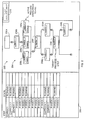
- FIG. 2 is a graphical user interface (GUI) of an example procedural function chart (PFC) view interface 200.
- the example PFC view interface 200 can be displayed by one or more of the application station 102, the operator station 104, and/or the workstation 118 of FIG. 1 .
- the example PFC view interface 200 includes a procedural function chart (PFC) 202 of an example recipe 204.
- the PFC 202 depicts a recipe having process steps or phases 206a-j to be executed in accordance with a pre-configured flow to implement a process.
- the predetermined flow of the recipe 204 involves executing the process step 206a followed by the process step 206b.
- the process steps 206c-e execute in parallel, and process step 206f executes after completion of the process steps 206c-e.
- the process steps 206g and 206h execute in parallel, and the process step 206i executes after completion of the process steps 206g and 206h.
- the process step 206j is executed. Control then returns to the process step 206f after the process step 206j is complete, and the process step 206f is re-executed.
- the recipe 204 in the illustrated example is implemented in accordance with process flow rules so that transitions between process steps do not violate any of the process flow rules (e.g., the ANSI/ISA S88 Batch Standard rules).
- the example methods and apparatus described herein can be used to modify a process flow during runtime of a recipe so that process steps can be executed out of order relative to a normal or pre-configured flow of a recipe, process steps that are not part of a pre-configured flow of a recipe can be made to execute as part of the recipe, and/or process steps of the pre-configured recipe can be eliminated.
- the PFC view interface 200 is provided with a one-click active step change (ASC) graphical button (or input control) 210 that can be selected by a user to modify the process flow of the recipe 204 during execution of the recipe 204.
- ASC active step change
- a user selects a process step change configuration module (e.g., one or more target process steps) to be activated and then selects or clicks on the one-click ASC button 210.
- the process step change configuration module includes the target process step 206i.
- the example methods and apparatus described herein automatically perform operations described below in response to selection of the one-click ASC button 210 to modify the process flow of the recipe 204 without requiring further interaction by the user.
- the amount of user interaction to perform an active step change to modify the flow of an executing recipe is kept to a substantially minimal amount, which in some cases may involve only selecting a process step change configuration module and clicking on the one-click ASC button 210 and in other cases may involve only clicking on the one-click ASC button 210.
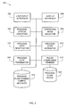
- FIG. 3 is a block diagram of an example apparatus 300 that may be used to dynamically modify recipes during their execution.
- the example apparatus 300 includes a user input interface 302, a display interface 304, a process status identifier 306, an operating mode selector 308, a process step deactivator 310, a process step activator 312, a process step terminator 314, a process flow change configuration modules data structure 316 (e.g., a database), a rules compliance verifier 318, and a process flow rules data structure 320 (e.g., a database), all of which may be communicatively coupled as shown or in any other suitable manner.
- the example apparatus 300 may be implemented using any desired combination of hardware, firmware, and/or software.
- one or more integrated circuits, discrete semiconductor components, or passive electronic components may be used.
- some or all of the blocks of the example apparatus 300, or parts thereof, may be implemented using instructions, code, and/or other software and/or firmware, etc. stored on a machine accessible medium that, when executed by, for example, a processor system (e.g., the processor system 510 of FIG. 5 ) perform the operations represented in the flow diagrams of FIGS. 4A and 4B .
- a processor system e.g., the processor system 510 of FIG. 5
- FIGS. 4A and 4B the example apparatus 300 is described as having one of each block described below, the example apparatus 300 may be provided with two or more of any block described below.
- some blocks may be disabled, omitted, or combined with other blocks.
- the example apparatus 300 is provided with the user input interface 302.
- the user input interface 302 may be implemented using a graphical user interface (GUI) and/or a mechanical (e.g., physical buttons) interface.
- GUI graphical user interface
- the user input interface 302 may be implemented using the PFC view interface 200 including the one-click ASC graphical button 210.
- the example apparatus 300 is provided with a display interface 304.
- the display interface 304 may be configured to display the PFC interface 200 and/or any other information related to modifying a recipe.
- the example apparatus is provided with the process status identifier 306.
- the process status identifier 306 may be used to determine which process steps or phases are being executed and whether process steps have completed execution.
- the process status information may be used to determine whether execution of a recipe is in a state that allows for safe removal of process steps and/or whether a wait period is required to permit a recipe transition to a particular state in which the recipe can be modified safely without, for example, adversely impacting product quality.
- the example apparatus 300 is provided with the operating mode selector 308.
- the operating mode selector 308 can be used to change the operating mode of a recipe from a normal execution mode to a halt mode, thereby causing any subsequent process steps of a recipe not to be executed. Such a change in operating modes can be used to prepare an executing recipe for an active step change.
- the example apparatus 300 is provided with the process step deactivator 310.
- the process step deactivator 310 can be configured to identify process steps that need to be deactivated to implement a process flow change in accordance with a process flow change configuration module selected by a user.
- the example apparatus 300 is provided with a process step activator 312.
- the process step activator 312 can be configured to identify process steps that are to be activated to implement a process flow change in accordance with a process flow change configuration module selected by a user.
- the example apparatus 300 is provided with the process step terminator 314.
- the process step terminator 314 can be configured to receive process status information from the process status identifier 306 to determine whether process steps are still being executed.
- the process step terminator 314 can receive information from process flow change configuration modules selected by users to determine which process steps can be prematurely terminated and which process steps must not be terminated prematurely. For example, during a design of a process flow change configuration module, a system engineer may identify that implementing a particular process flow change will occur after execution of another process flow change.
- the system engineer can create a setting in the process flow change configuration module instructing that the process step terminator 314 should not prematurely terminate the executing process step and that the example apparatus 300 should instead wait to implement the requested process flow change until the process status identifier 306 determines that the executing process step has ended on its own.
- the process step terminator 314 can additionally or alternatively determine whether a process step can be prematurely terminated based on rules stored in the process flow rules database 320.
- the example apparatus 300 To store process flow change configuration modules indicative of process flow changes that can be selected by users, the example apparatus 300 is provided with the process flow change configuration modules data structure 316. To determine whether requested process flow changes comply with process flow rules, the example apparatus 300 is provided with the rules compliance verifier 318 and the process flow rules database 320.
- the process flow rules database 320 is configured to store rules with which process flows changes must comply to ensure safe operation and/or maintaining product quality. For example, the process flow rules may indicate that certain process steps must be executed in parallel or in seriatim. The process flow rules may also indicate that certain process flow modifications cannot be implemented until other currently executing recipes are finished or release equipment (e.g., the tank 122, the mixers 124a-c of FIG. 1 , etc.) necessary to execute the proposed modified process flow.
- the rules compliance verifier 316 is configured to verify that the process flow changes to be made based on a selected process flow change configuration module comply with the rules stored in the process flow rules database 320. If any process flow change violates a rule, the display interface 304 can display an error message.
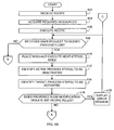
- FIGS. 4A and 4B depict a flow diagram of an example method that may be used to implement the example apparatus 300 of FIG. 3 to modify a process flow of a recipe during execution of the recipe.
- the example method of FIGS. 4A and 4B may be implemented using machine readable instructions comprising a program for execution by a processor (e.g., the processor 512 shown in the example processor system 510 of FIG. 5 ).
- the program may be embodied in software stored on a tangible medium such as a CD-ROM, a floppy disk, a hard drive, a digital versatile disk (DVD), or a memory associated with the processor 512 and/or embodied in firmware and/or dedicated hardware in a well-known manner.
- example program is described with reference to the flow diagram illustrated in FIGS. 4A and 4B , persons of ordinary skill in the art will readily appreciate that many other methods of implementing the example apparatus 300 may alternatively be used. For example, the order of execution of the blocks may be changed, and/or some of the blocks described may be changed, eliminated, or combined.
- a batch processor receives the recipe 204 (block 402) and acquires resources (e.g., the controller 106, one or more tanks 122, one or more of the mixers 124a-c, one or more of the field devices 112a-e, etc.) required to execute the recipe 204 (block 404).
- resources e.g., the controller 106, one or more tanks 122, one or more of the mixers 124a-c, one or more of the field devices 112a-e, etc.
- the batch processor can acquire resources for only the unit procedure that is about to execute.
- the batch processor can release the acquired resources for that unit procedure and acquire other resources for a subsequent unit procedure.
- the batch processor then executes the recipe 204 (block 406).
- the user input interface 302 determines whether it has received a user request to modify the process flow of the recipe 204 (block 408).
- the user input interface 302 receives a user request to modify the process flow (i.e., a process change request) when a user has selected a process flow change configuration module from the process flow change configuration modules database 316 ( FIG. 3 ) and selects the one-click ASC button 210 of FIG. 2 .
- the operating mode selector 308 places the execution of the recipe 204 in a do-not-execute-next-step(s) mode (block 410).
- the do-not-execute-next-step(s) mode prevents the batch processor from executing the process steps or phases that sequentially follow the currently executing process step(s) to enable the example apparatus 300 to modify the process flow of the recipe 204 after completion of the currently executing process step(s), but before another process step begins execution.
- the do-not-execute-next-step(s) mode prevents the process steps 206f from executing after the process steps 206c-e finish executing.
- the process step deactivator 310 ( FIG. 3 ) then identifies (or selects) the currently active process step(s) to be deactivated (block 412) based on the process flow change configuration module provided by the user at block 408.
- the process steps 206c-e are the currently active step(s) to be deactivated because those steps were running when the batch processor received the user selection to modify the process flow at block 408.
- the process step activator 312 then identifies one or more target process steps to be activated (block 414).
- the process flow change configuration module indicates that the phase 206i is the target process step to be activated.
- the rules compliance verifier 318 determines whether the flow modification proposed in the process flow change configuration module violates any process flow rules (block 416) by, for example, comparing characteristics of the target step 206i and the characteristics of the current active process steps (e.g., the process steps 206c-e) with process flow rules to ensure that the transition does not violate any of the process flow rules. If the rules compliance verifier 318 determines that the proposed flow modification violates one or more process flow rules (block 416), the display interface 304 displays an error message (block 418) and control returns to block 408.
- the process status identifier 306 determines whether the execution of the currently active process steps 206c-e is complete (block 420) ( FIG. 4B ). If the execution of the currently active process steps 206c-e is not complete (block 420), the process step terminator 314 ( FIG. 3 ) determines whether it should terminate execution of the active process steps 206c-e (block 422). Some process steps may be terminated prematurely without affecting the product being produced, while other process steps should not be terminated prematurely because doing so may have an adverse or unwanted effect on the product or may otherwise be undesirable.
- Rules indicative of whether a process step can be terminated prematurely may be stored in the process flow change configuration module selected by the user. Additionally or alternatively, the process step terminator 314 can use the rules stored in the process flow rules database 320 to determine whether a step can be terminated.
- the process step deactivator 312 deactivates the completed active steps 206c-e and the intervening steps 206f-h between the process steps 206c-e and the process step 206i (block 426).
- the process step activator 312 then activates the target process step 206i (block 428), and the operating mode selector 308 places the execution of the recipe 204 in an execution mode (block 430).
- the batch processor then executes the user-selected target process step 206i (block 432).
- the process status identifier 306 determines whether the recipe 204 has completed execution (block 434). If the recipe execution has not completed, control returns to block 408 ( FIG. 4A ). Otherwise, the example process of FIGS. 4A and 4B is ended.
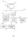
- FIG. 5 is a block diagram of an example processor system 510 that may be used to implement the apparatus and methods described herein.
- the processor system 510 includes a processor 512 that is coupled to an interconnection bus 514.
- the processor 512 includes a register set or register space 516, which is depicted in FIG. 5 as being entirely on-chip, but which could alternatively be located entirely or partially off-chip and directly coupled to the processor 512 via dedicated electrical connections and/or via the interconnection bus 514.
- the processor 512 may be any suitable processor, processing unit or microprocessor.
- the system 510 may be a multi-processor system and, thus, may include one or more additional processors that are identical or similar to the processor 512 and that are communicatively coupled to the interconnection bus 514.
- the processor 512 of FIG. 5 is coupled to a chipset 518, which includes a memory controller 520 and a peripheral input/output (I/O) controller 522.
- a chipset typically provides I/O and memory management functions as well as a plurality of general purpose and/or special purpose registers, timers, etc. that are accessible or used by one or more processors coupled to the chipset 518.
- the memory controller 520 performs functions that enable the processor 512 (or processors if there are multiple processors) to access a system memory 524 and a mass storage memory 525.
- the system memory 524 may include any desired type of volatile and/or non-volatile memory such as, for example, static random access memory (SRAM), dynamic random access memory (DRAM), flash memory, read-only memory (ROM), etc.
- the mass storage memory 525 may include any desired type of mass storage device including hard disk drives, optical drives, tape storage devices, etc.
- the peripheral I/O controller 522 performs functions that enable the processor 512 to communicate with peripheral input/output (I/O) devices 526 and 528 and a network interface 530 via a peripheral I/O bus 532.
- the I/O devices 526 and 528 may be any desired type of I/O device such as, for example, a keyboard, a video display or monitor, a mouse, etc.
- the network interface 530 may be, for example, an Ethernet device, an asynchronous transfer mode (ATM) device, an 802.11 device, a DSL modem, a cable modem, a cellular modem, etc. that enables the processor system 510 to communicate with another processor system.
- ATM asynchronous transfer mode
- memory controller 520 and the I/O controller 522 are depicted in FIG. 5 as separate functional blocks within the chipset 518, the functions performed by these blocks may be integrated within a single semiconductor circuit or may be implemented using two or more separate integrated circuits.
Landscapes
- Engineering & Computer Science (AREA)
- Physics & Mathematics (AREA)
- General Physics & Mathematics (AREA)
- Automation & Control Theory (AREA)
- General Engineering & Computer Science (AREA)
- Manufacturing & Machinery (AREA)
- Quality & Reliability (AREA)
- General Factory Administration (AREA)
- Stored Programmes (AREA)
- Management, Administration, Business Operations System, And Electronic Commerce (AREA)
- Control By Computers (AREA)
Applications Claiming Priority (1)
| Application Number | Priority Date | Filing Date | Title |
|---|---|---|---|
| US11/939,304 US8150541B2 (en) | 2007-11-13 | 2007-11-13 | Methods and apparatus to modify a recipe process flow associated with a process control system during recipe execution |
Publications (3)
| Publication Number | Publication Date |
|---|---|
| EP2109022A2 EP2109022A2 (en) | 2009-10-14 |
| EP2109022A3 EP2109022A3 (en) | 2010-11-03 |
| EP2109022B1 true EP2109022B1 (en) | 2013-10-16 |
Family
ID=40139716
Family Applications (1)
| Application Number | Title | Priority Date | Filing Date |
|---|---|---|---|
| EP08168837.6A Active EP2109022B1 (en) | 2007-11-13 | 2008-11-11 | Methods and apparatus to modify a recipe process flow associated with a process control system during recipe execution |
Country Status (5)
| Country | Link |
|---|---|
| US (1) | US8150541B2 (enExample) |
| EP (1) | EP2109022B1 (enExample) |
| JP (1) | JP5995395B2 (enExample) |
| CN (1) | CN101436064B (enExample) |
| GB (1) | GB2454785B (enExample) |
Families Citing this family (14)
| Publication number | Priority date | Publication date | Assignee | Title |
|---|---|---|---|---|
| US8612886B2 (en) * | 2007-09-28 | 2013-12-17 | Rockwell Automation Technologies, Inc. | Sequential function chart (SFC) online editing without reset |
| US8825189B2 (en) * | 2007-11-13 | 2014-09-02 | Fisher Rosemount Systems, Inc. | Methods and apparatus to execute an auxiliary recipe and a batch recipe associated with a process control system |
| US8555206B2 (en) * | 2007-12-21 | 2013-10-08 | Fisher-Rosemount Systems, Inc. | Methods and apparatus to present recipe progress status information |
| US8606379B2 (en) * | 2008-09-29 | 2013-12-10 | Fisher-Rosemount Systems, Inc. | Method of generating a product recipe for execution in batch processing |
| US9014827B2 (en) * | 2010-01-14 | 2015-04-21 | International Business Machines Corporation | Dynamically generating a manufacturing production work flow with selectable sampling strategies |
| JP2012114157A (ja) * | 2010-11-22 | 2012-06-14 | Toshiba Corp | ドロップレシピ作成方法およびデータベース作成方法 |
| US8718807B2 (en) * | 2012-03-23 | 2014-05-06 | Honeywell International Inc. | System and method for robust real-time control of regular automated production using master recipe |
| US9280151B2 (en) * | 2012-05-15 | 2016-03-08 | Wafertech, Llc | Recipe management system and method |
| NZ758450A (en) * | 2017-05-29 | 2025-10-31 | Tetra Laval Holdings & Finance | Process control for production of liquid food |
| US10593319B1 (en) * | 2017-06-27 | 2020-03-17 | Amazon Technologies, Inc. | Parallelization of instruction steps |
| GB201904231D0 (en) | 2019-03-27 | 2019-05-08 | Ge Healthcare Bio Sciences Ab | A method and system for monitoring a bio-pharmaceutical process |
| JP6957669B2 (ja) * | 2019-09-04 | 2021-11-02 | 株式会社東芝 | 可視化システム |
| JP7345337B2 (ja) * | 2019-09-24 | 2023-09-15 | 株式会社富士通エフサス | 情報処理装置、情報処理方法および情報処理プログラム |
| US12079753B2 (en) * | 2020-10-22 | 2024-09-03 | Open Text Corporation | Lifecycle fragment and dynamic discovery of lifecycle fragment at runtime |
Family Cites Families (104)
| Publication number | Priority date | Publication date | Assignee | Title |
|---|---|---|---|---|
| US4500687A (en) | 1981-06-18 | 1985-02-19 | The Dow Chemical Company | Elastomeric polyether-containing impact polymer products |
| US4570217A (en) | 1982-03-29 | 1986-02-11 | Allen Bruce S | Man machine interface |
| US4636949A (en) | 1984-03-07 | 1987-01-13 | Amf Incorporated | Method and apparatus for controlling cooking cycles in a cooking system |
| DK196786A (da) * | 1986-04-29 | 1987-10-30 | Ebbe Busch Larsen | Fremgangsmoede og middel til styring af et foderblandingsanlaeg |
| US4885677A (en) * | 1986-07-21 | 1989-12-05 | The Babcock & Wilcox Company | Automatic system for sequential control and fault detection of devices used in batch processes |
| US5058043A (en) * | 1989-04-05 | 1991-10-15 | E. I. Du Pont De Nemours & Co. (Inc.) | Batch process control using expert systems |
| US5113350A (en) * | 1989-08-25 | 1992-05-12 | Beowulf Corporation | Computerized system for display and storage of materials batching information |
| US5355320A (en) | 1992-03-06 | 1994-10-11 | Vlsi Technology, Inc. | System for controlling an integrated product process for semiconductor wafers and packages |
| GB9211539D0 (en) | 1992-06-01 | 1992-07-15 | Ducost Eng Ltd | Control of paint spraying machines and the like |
| JP3234949B2 (ja) * | 1992-12-14 | 2001-12-04 | ハネウエル・インコーポレーテッド | プロセス制御システムにおいてレシピを作成するフレキシブルな方法 |
| JPH06325992A (ja) * | 1993-05-13 | 1994-11-25 | Matsushita Electric Ind Co Ltd | プロセスフロー作成装置 |
| US5631825A (en) | 1993-09-29 | 1997-05-20 | Dow Benelux N.V. | Operator station for manufacturing process control system |
| US5576946A (en) | 1993-09-30 | 1996-11-19 | Fluid Air, Inc. | Icon based process design and control system |
| US5644686A (en) | 1994-04-29 | 1997-07-01 | International Business Machines Corporation | Expert system and method employing hierarchical knowledge base, and interactive multimedia/hypermedia applications |
| US5719559A (en) * | 1995-06-23 | 1998-02-17 | Limitorque Corporation | System and method for the verification of a digital control system |
| US6762036B2 (en) * | 1995-11-08 | 2004-07-13 | Trustees Of Boston University | Cellular physiology workstations for automated data acquisition and perfusion control |
| US5970243A (en) * | 1996-08-27 | 1999-10-19 | Steeplechase Software, Inc. | Online programming changes for industrial logic controllers |
| JP3778652B2 (ja) * | 1997-04-18 | 2006-05-24 | 株式会社日立製作所 | ログデータ収集管理方法及びその装置 |
| US6000830A (en) * | 1997-04-18 | 1999-12-14 | Tokyo Electron Limited | System for applying recipe of semiconductor manufacturing apparatus |
| US6983229B2 (en) * | 1997-06-20 | 2006-01-03 | Brown Peter G | Method for scheduling solution preparation in biopharmaceutical batch process manufacturing |
| US5990906A (en) | 1997-06-25 | 1999-11-23 | National Instruments Corporation | Undo feature for a graphical programming system |
| US6507765B1 (en) | 1998-02-10 | 2003-01-14 | Hm Electronic Systems Limited | Computer integrated manufacturing control and information system |
| JPH11235648A (ja) * | 1998-02-17 | 1999-08-31 | Toshiba Corp | 製造計画管理装置、製造計画管理方法、及び、製造計画管理プログラムを記録したコンピュータ読み取り可能な記録媒体 |
| US6148244A (en) | 1998-04-13 | 2000-11-14 | Intellution, Inc. | Equipment pathing and unit allocation for a process control system |
| US6296711B1 (en) | 1998-04-14 | 2001-10-02 | Cvd Systems, Inc. | Film processing system |
| US6535122B1 (en) | 1998-05-01 | 2003-03-18 | Invensys Systems, Inc. | Method and apparatus for extending processing mask/filtering, and displaying alarm information for a hierarchically categorizing alarm monitoring system |
| US6690274B1 (en) | 1998-05-01 | 2004-02-10 | Invensys Systems, Inc. | Alarm analysis tools method and apparatus |
| US6292708B1 (en) * | 1998-06-11 | 2001-09-18 | Speedfam-Ipec Corporation | Distributed control system for a semiconductor wafer processing machine |
| US6615091B1 (en) | 1998-06-26 | 2003-09-02 | Eveready Battery Company, Inc. | Control system and method therefor |
| US6289252B1 (en) * | 1998-08-31 | 2001-09-11 | Fisher-Rosemount Systems, Inc. | Distributed batch processing system and methods |
| US6571191B1 (en) * | 1998-10-27 | 2003-05-27 | Cummins, Inc. | Method and system for recalibration of an electronic control module |
| US6629003B1 (en) * | 1998-12-04 | 2003-09-30 | Vector Corporation | Batch processing control system recipe management and batch information system |
| US6385496B1 (en) * | 1999-03-12 | 2002-05-07 | Fisher-Rosemount Systems, Inc. | Indirect referencing in process control routines |
| US6647301B1 (en) | 1999-04-22 | 2003-11-11 | Dow Global Technologies Inc. | Process control system with integrated safety control system |
| US6952808B1 (en) | 1999-07-01 | 2005-10-04 | Honeywell Inc. | Process variable gauge interface and methods regarding same |
| US6522934B1 (en) * | 1999-07-02 | 2003-02-18 | Fisher-Rosemount Systems, Inc. | Dynamic unit selection in a process control system |
| US6415193B1 (en) * | 1999-07-08 | 2002-07-02 | Fabcentric, Inc. | Recipe editor for editing and creating process recipes with parameter-level semiconductor-manufacturing equipment |
| US6834370B1 (en) * | 1999-07-08 | 2004-12-21 | Osi Software, Inc. | Method for creating master recipes |
| US6385552B1 (en) | 1999-08-10 | 2002-05-07 | Tyco Telecommunications (Us) Inc. | Method for collecting test measurements |
| US6542841B1 (en) | 1999-08-10 | 2003-04-01 | Tyco Telecommunications (Us) Inc. | Method for managing test measurements |
| US6415246B1 (en) | 1999-08-10 | 2002-07-02 | Tyco Telecommunications (Us) Inc. | Method for limit checking |
| US6488037B1 (en) * | 1999-08-31 | 2002-12-03 | Texas Instruments Incorporated | Programmable physical action during integrated circuit wafer cleanup |
| IL132663A (en) * | 1999-10-31 | 2004-06-01 | Insyt Ltd | Protocol system for knowledge engineering |
| US6901582B1 (en) | 1999-11-24 | 2005-05-31 | Quest Software, Inc. | Monitoring system for monitoring the performance of an application |
| US6865509B1 (en) * | 2000-03-10 | 2005-03-08 | Smiths Detection - Pasadena, Inc. | System for providing control to an industrial process using one or more multidimensional variables |
| DE10112681B4 (de) * | 2000-03-31 | 2004-02-12 | International Business Machines Corp. | Computersystem mit Verfahren zum Planen von Vorgängen in einem Stahlwerk und Programmspeichereinrichtung zum Durchführen des Verfahrens |
| US6606527B2 (en) * | 2000-03-31 | 2003-08-12 | International Business Machines Corporation | Methods and systems for planning operations in manufacturing plants |
| JP2001284203A (ja) * | 2000-04-04 | 2001-10-12 | Matsushita Electric Ind Co Ltd | 半導体プロセスフロー変更方法及び半導体プロセスフロー変更装置 |
| WO2001077872A2 (en) * | 2000-04-05 | 2001-10-18 | Pavilion Technologies, Inc. | System and method for enterprise modeling, optimization and control |
| US6947917B1 (en) * | 2000-04-14 | 2005-09-20 | Honeywell International Inc. | Advanced recipe—a knowledge based information system for production processes |
| US7020876B1 (en) * | 2000-06-30 | 2006-03-28 | Fisher-Rosemount Systems, Inc. | Campaign management for batch processes |
| JP2002023823A (ja) * | 2000-07-12 | 2002-01-25 | Mitsubishi Electric Corp | 生産管理システム |
| SG148839A1 (en) * | 2000-07-31 | 2009-01-29 | Celerity Inc | Method and apparatus for blending process materials |
| US6791692B2 (en) | 2000-11-29 | 2004-09-14 | Lightwind Corporation | Method and device utilizing plasma source for real-time gas sampling |
| JP2002359237A (ja) * | 2001-05-30 | 2002-12-13 | Hitachi Kokusai Electric Inc | 基板処理装置および半導体装置の製造方法 |
| TWI279657B (en) * | 2001-09-21 | 2007-04-21 | Olympus Corp | Management apparatus |
| JP2003132093A (ja) | 2001-10-29 | 2003-05-09 | Nippon Steel Corp | データログシステム |
| US6975921B2 (en) | 2001-11-09 | 2005-12-13 | Asm International Nv | Graphical representation of a wafer processing process |
| US7032816B2 (en) * | 2001-12-28 | 2006-04-25 | Kimberly-Clark Worldwide, Inc. | Communication between machines and feed-forward control in event-based product manufacturing |
| US6732006B2 (en) * | 2002-02-06 | 2004-05-04 | Asm International Nv | Method and system to process semiconductor wafers |
| JP2003263221A (ja) | 2002-03-07 | 2003-09-19 | Mitsubishi Electric Corp | 時系列認識装置、時系列認識方法及びプログラム |
| US6976033B2 (en) | 2002-04-10 | 2005-12-13 | Charming Systems Corpration | Production cell information system based on activity costs and an architecture therefor |
| US6697690B2 (en) * | 2002-04-15 | 2004-02-24 | Sap Aktiengesellschaft | Customizing process flows |
| WO2004006299A2 (en) * | 2002-07-03 | 2004-01-15 | Tokyo Electron Limited | Method for dynamic sensor configuration and runtime execution |
| US20040019393A1 (en) * | 2002-07-25 | 2004-01-29 | Eileen Heider | System and method for model base control |
| US7310798B1 (en) | 2002-08-19 | 2007-12-18 | Sprint Communications Company L.P. | Simulator tool for testing software in development process |
| US7092771B2 (en) | 2002-11-14 | 2006-08-15 | Rockwell Automation Technologies, Inc. | Industrial control and monitoring method and system |
| US7275062B2 (en) * | 2003-03-10 | 2007-09-25 | Fisher-Rosemount Systems, Inc. | Automatic linkage of process event data to a data historian |
| US7369912B2 (en) | 2003-05-29 | 2008-05-06 | Fisher-Rosemount Systems, Inc. | Batch execution engine with independent batch execution processes |
| KR100506926B1 (ko) * | 2003-07-16 | 2005-08-09 | 삼성전자주식회사 | 단일경로용 작업시스템 및 그 제어방법 |
| US7149595B2 (en) | 2003-08-13 | 2006-12-12 | Rockwell Automation Technologies, Inc. | Material classification system and methods |
| US20050052659A1 (en) | 2003-09-05 | 2005-03-10 | Jacobsen Dana A. | Progress indicator for graphical display on printers |
| CA2549057C (en) | 2003-12-19 | 2014-08-19 | Steve Townsend | Software and methods for automated pallet inspection and repair |
| US7369913B2 (en) * | 2004-04-02 | 2008-05-06 | Siemens Medical Solutions Usa, Inc. | Recipe editor and controller |
| JP2005309486A (ja) | 2004-04-16 | 2005-11-04 | Mitsubishi Electric Corp | 運転履歴データ管理装置及び運転履歴データ管理システム |
| US7179664B2 (en) * | 2004-05-06 | 2007-02-20 | Taiwan Semiconductor Manufacturing Company | Method for generating work-in-process schedules |
| US7926024B2 (en) | 2004-06-14 | 2011-04-12 | Hyperformix, Inc. | Method and apparatus for managing complex processes |
| JP4664630B2 (ja) | 2004-07-22 | 2011-04-06 | 株式会社東芝 | 半導体装置の製造装置に対する自動レシピ作成装置及び作成方法 |
| KR100643492B1 (ko) * | 2004-07-23 | 2006-11-10 | 삼성전자주식회사 | 전자 네트워크 시스템상에서 조직구성원 간의 신뢰형성을위한 서비스 제공방법 |
| US7464366B2 (en) | 2004-10-01 | 2008-12-09 | Microsoft Corporation | Programming interface for a componentized and extensible workflow model |
| US7680970B2 (en) | 2004-10-22 | 2010-03-16 | Fisher-Rosemount Systems, Inc. | Method and system for batch process arbitration in a process control system |
| US7477960B2 (en) | 2005-02-16 | 2009-01-13 | Tokyo Electron Limited | Fault detection and classification (FDC) using a run-to-run controller |
| JP4903012B2 (ja) | 2005-05-26 | 2012-03-21 | 株式会社リコー | ワークフローシステム、ワークフロー処理方法およびワークフロー処理プログラム |
| US20070005170A1 (en) * | 2005-06-29 | 2007-01-04 | Thorsten Schedel | Method for the preferred processing of workpieces of highest priority |
| EP1913533A1 (en) * | 2005-08-05 | 2008-04-23 | Pfizer Products Incorporated | Automated batch manufacturing |
| US20070038889A1 (en) | 2005-08-11 | 2007-02-15 | Wiggins Robert D | Methods and systems to access process control log information associated with process control systems |
| KR100719375B1 (ko) | 2005-10-12 | 2007-05-17 | 삼성전자주식회사 | 반도체 설비의 페일오버 시스템 및 방법 |
| US7738973B2 (en) | 2005-11-14 | 2010-06-15 | Rockwell Automation Technologies, Inc. | Distributed historian architecture and interfaces |
| US7571019B2 (en) * | 2005-12-30 | 2009-08-04 | Intel Corporation | Integrated configuration, flow and execution system for semiconductor device experimental flows and production flows |
| US8600539B2 (en) | 2006-01-27 | 2013-12-03 | Hitachi Kokusai Electric Inc. | Substrate processing apparatus |
| US20070179634A1 (en) | 2006-01-27 | 2007-08-02 | The Procter & Gamble Company | Method of controlling a process |
| DE102006004413A1 (de) * | 2006-01-31 | 2007-08-09 | Advanced Micro Devices, Inc., Sunnyvale | Verfahren und System zum Disponieren eines Produktstromes in einer Fertigungsumgebung durch Anwendung eines Simulationsprozesses |
| JP4839101B2 (ja) * | 2006-03-08 | 2011-12-21 | 東京エレクトロン株式会社 | 基板処理装置、基板処理条件検討方法及び記憶媒体 |
| JP2007266482A (ja) | 2006-03-29 | 2007-10-11 | Toshiba Corp | 生産システム及び電子装置の製造方法 |
| US7519885B2 (en) * | 2006-03-31 | 2009-04-14 | Tokyo Electron Limited | Monitoring a monolayer deposition (MLD) system using a built-in self test (BIST) table |
| US7630777B2 (en) | 2006-07-06 | 2009-12-08 | Honeywell International Inc. | Apparatus and method for configurable process automation in a process control system |
| US7793292B2 (en) | 2006-09-13 | 2010-09-07 | Fisher-Rosemount Systems, Inc. | Compact batch viewing techniques for use in batch processes |
| US8078296B2 (en) | 2006-09-29 | 2011-12-13 | Rockwell Automation Technologies, Inc. | Dynamic procedure selection |
| JP4942174B2 (ja) | 2006-10-05 | 2012-05-30 | 東京エレクトロン株式会社 | 基板処理システムの処理レシピ最適化方法,基板処理システム,基板処理装置 |
| DE102006056143A1 (de) | 2006-11-28 | 2007-10-11 | Siemens Ag | Verfahren zur Synchronisation von Steuerrezepten |
| US20080172629A1 (en) | 2007-01-17 | 2008-07-17 | Microsoft Corporation | Geometric Performance Metric Data Rendering |
| US8369975B2 (en) | 2007-09-21 | 2013-02-05 | Fisher-Rosemount Systems, Inc. | Online recipe synchronization in a real-time batch executive environment |
| US8825189B2 (en) | 2007-11-13 | 2014-09-02 | Fisher Rosemount Systems, Inc. | Methods and apparatus to execute an auxiliary recipe and a batch recipe associated with a process control system |
| US8555206B2 (en) | 2007-12-21 | 2013-10-08 | Fisher-Rosemount Systems, Inc. | Methods and apparatus to present recipe progress status information |
-
2007
- 2007-11-13 US US11/939,304 patent/US8150541B2/en active Active
-
2008
- 2008-11-11 GB GB0820601.3A patent/GB2454785B/en active Active
- 2008-11-11 EP EP08168837.6A patent/EP2109022B1/en active Active
- 2008-11-13 JP JP2008290570A patent/JP5995395B2/ja active Active
- 2008-11-13 CN CN2008101764657A patent/CN101436064B/zh active Active
Also Published As
| Publication number | Publication date |
|---|---|
| US20090125126A1 (en) | 2009-05-14 |
| GB2454785B (en) | 2013-10-09 |
| JP2009123213A (ja) | 2009-06-04 |
| CN101436064A (zh) | 2009-05-20 |
| CN101436064B (zh) | 2013-03-06 |
| JP5995395B2 (ja) | 2016-09-21 |
| GB2454785A (en) | 2009-05-20 |
| EP2109022A2 (en) | 2009-10-14 |
| US8150541B2 (en) | 2012-04-03 |
| EP2109022A3 (en) | 2010-11-03 |
| GB0820601D0 (en) | 2008-12-17 |
Similar Documents
| Publication | Publication Date | Title |
|---|---|---|
| EP2109022B1 (en) | Methods and apparatus to modify a recipe process flow associated with a process control system during recipe execution | |
| EP2853967B1 (en) | Apparatus to execute an auxiliary recipe and a batch recipe associated with a process control system | |
| US7369912B2 (en) | Batch execution engine with independent batch execution processes | |
| US9008814B2 (en) | Online recipe synchronization in a real-time batch executive environment | |
| EP2110720B1 (en) | Methods and apparatus to present recipe progress status information | |
| US8606379B2 (en) | Method of generating a product recipe for execution in batch processing |
Legal Events
| Date | Code | Title | Description |
|---|---|---|---|
| PUAI | Public reference made under article 153(3) epc to a published international application that has entered the european phase |
Free format text: ORIGINAL CODE: 0009012 |
|
| AK | Designated contracting states |
Kind code of ref document: A2 Designated state(s): AT BE BG CH CY CZ DE DK EE ES FI FR GB GR HR HU IE IS IT LI LT LU LV MC MT NL NO PL PT RO SE SI SK TR |
|
| AX | Request for extension of the european patent |
Extension state: AL BA MK RS |
|
| PUAL | Search report despatched |
Free format text: ORIGINAL CODE: 0009013 |
|
| AK | Designated contracting states |
Kind code of ref document: A3 Designated state(s): AT BE BG CH CY CZ DE DK EE ES FI FR GB GR HR HU IE IS IT LI LT LU LV MC MT NL NO PL PT RO SE SI SK TR |
|
| AX | Request for extension of the european patent |
Extension state: AL BA MK RS |
|
| 17P | Request for examination filed |
Effective date: 20110503 |
|
| AKX | Designation fees paid |
Designated state(s): DE GB |
|
| 17Q | First examination report despatched |
Effective date: 20120509 |
|
| GRAP | Despatch of communication of intention to grant a patent |
Free format text: ORIGINAL CODE: EPIDOSNIGR1 |
|
| INTG | Intention to grant announced |
Effective date: 20130424 |
|
| GRAS | Grant fee paid |
Free format text: ORIGINAL CODE: EPIDOSNIGR3 |
|
| GRAA | (expected) grant |
Free format text: ORIGINAL CODE: 0009210 |
|
| AK | Designated contracting states |
Kind code of ref document: B1 Designated state(s): DE GB |
|
| REG | Reference to a national code |
Ref country code: GB Ref legal event code: FG4D |
|
| REG | Reference to a national code |
Ref country code: DE Ref legal event code: R096 Ref document number: 602008028096 Country of ref document: DE Effective date: 20131212 |
|
| REG | Reference to a national code |
Ref country code: DE Ref legal event code: R097 Ref document number: 602008028096 Country of ref document: DE |
|
| PLBE | No opposition filed within time limit |
Free format text: ORIGINAL CODE: 0009261 |
|
| STAA | Information on the status of an ep patent application or granted ep patent |
Free format text: STATUS: NO OPPOSITION FILED WITHIN TIME LIMIT |
|
| 26N | No opposition filed |
Effective date: 20140717 |
|
| REG | Reference to a national code |
Ref country code: DE Ref legal event code: R097 Ref document number: 602008028096 Country of ref document: DE Effective date: 20140717 |
|
| P01 | Opt-out of the competence of the unified patent court (upc) registered |
Effective date: 20230526 |
|
| PGFP | Annual fee paid to national office [announced via postgrant information from national office to epo] |
Ref country code: DE Payment date: 20241022 Year of fee payment: 17 |
|
| PGFP | Annual fee paid to national office [announced via postgrant information from national office to epo] |
Ref country code: GB Payment date: 20241022 Year of fee payment: 17 |