EP2108771A2 - Treibstangenschloss - Google Patents
Treibstangenschloss Download PDFInfo
- Publication number
- EP2108771A2 EP2108771A2 EP09154456A EP09154456A EP2108771A2 EP 2108771 A2 EP2108771 A2 EP 2108771A2 EP 09154456 A EP09154456 A EP 09154456A EP 09154456 A EP09154456 A EP 09154456A EP 2108771 A2 EP2108771 A2 EP 2108771A2
- Authority
- EP
- European Patent Office
- Prior art keywords
- espagnolette
- teeth
- projection
- drive pinion
- slide
- Prior art date
- Legal status (The legal status is an assumption and is not a legal conclusion. Google has not performed a legal analysis and makes no representation as to the accuracy of the status listed.)
- Granted
Links
Images


Classifications
-
- E—FIXED CONSTRUCTIONS
- E05—LOCKS; KEYS; WINDOW OR DOOR FITTINGS; SAFES
- E05C—BOLTS OR FASTENING DEVICES FOR WINGS, SPECIALLY FOR DOORS OR WINDOWS
- E05C9/00—Arrangements of simultaneously actuated bolts or other securing devices at well-separated positions on the same wing
- E05C9/02—Arrangements of simultaneously actuated bolts or other securing devices at well-separated positions on the same wing with one sliding bar for fastening when moved in one direction and unfastening when moved in opposite direction; with two sliding bars moved in the same direction when fastening or unfastening
- E05C9/021—Arrangements of simultaneously actuated bolts or other securing devices at well-separated positions on the same wing with one sliding bar for fastening when moved in one direction and unfastening when moved in opposite direction; with two sliding bars moved in the same direction when fastening or unfastening with rack and pinion mechanism
- E05C9/023—Arrangements of simultaneously actuated bolts or other securing devices at well-separated positions on the same wing with one sliding bar for fastening when moved in one direction and unfastening when moved in opposite direction; with two sliding bars moved in the same direction when fastening or unfastening with rack and pinion mechanism between a lock cylinder and the bar
Definitions
- the invention relates to an espagnolette with a longitudinally displaceable guided, a row of teeth having espagnolette slide and with a drivable, teeth of the row of teeth of the espagnolette drive pinion meshing drive pinion.
- Such espagnolette is from the EP 0 141 891 A1 known.
- a portion of the espagnolette gate valve is formed as a rack with the teeth.
- the drive pinion has on its circumference a wreath teeth. This can be moved comfortably and smoothly by driving the drive pinion of the espagnolette slide and thus connected to the espagnolette drive rod drive. Conversely, by shifting the espagnolette slide, for example by driving the drive rod by hand, the drive pinion can rotate.
- the espagnolette lock provides no protection against unauthorized movement of the drive rod.
- a espagnolette lock with a self-locking drive of the espagnolette slide is for example from EP 1 496 177 B1 known.
- the drive pinion has on one end side two protruding drive pins.
- the drive pins penetrate between protruding lugs of the espagnolette slide.
- the drive pins move the lugs of the espagnolette gate valve.
- the drive pins block movement of the espagnolette slide.
- the drive of the espagnolette slide is thus designed to be self-locking.
- the invention is based on the problem of further developing an espagnolette lock of the kind set forth so that the espagnolette gate valve can be driven continuously and smoothly and that a displacement of the espagnolette gate valve from an end position is blocked without driving the drive pinion.
- the drive pinion has a projection with a protruding edge and that the edge is arranged in the end position befindliches grasperies grasperies grasperies grasperies grasperies grasping a tooth of the espagnolette slide and a pivot point of the drive pinion.
- the teeth are pressed against the edge of the projection in an attempted displacement of the espagnolette slide without driving the drive pinion, so that the drive pinion in the direction their fulcrum is pressed.
- a rotation of the drive pinion by a displacement of the espagnolette from the end position out is blocked.
- the edge of the projection is moved out of the range of movement of the teeth of the espagnolette slide.
- the teeth of the partial toothed ring reach into the row of teeth of the espagnolette slide. This allows a continuous and particularly comfortable drive of the espagnolette by a rotation of the drive pinion.
- the espagnolette lock according to the invention is particularly simple if the drive sprocket has a partial sprocket with only a portion of the circumference extending teeth when the projection on the circumference of the drive pinion is disposed immediately adjacent to the sprocket, when the projection is wider than a tooth of the sprocket , if the espagnolette slide immediately adjacent to the row of teeth has a pocket with a width corresponding to the projection and protrudes in the end position befindliches espagnolette slide the projection exclusively with a portion in the bag.
- the drive of the sprocket in befindlichem in the end position espagnolette by the projection is particularly comfortable when the projection has the width of several teeth of the sprocket and when the distance of the protrusion of the next tooth of the sprocket corresponds to the distance of a plurality of teeth of the sprocket. Furthermore, this promotes the projection in the drive of the drive pinion the espagnolette slide such that the teeth of the partial toothed ring without the risk of entanglement in the row of teeth are performed. Furthermore, this can be the Bag be made as a simple tooth gap. This makes the espagnolette slide particularly easy to manufacture.
- the projection has according to another advantageous embodiment of the invention particularly comfortable Abrolligenschaften when flanks of the protrusion have substantially the shape of flanks of the teeth of the sprocket. This means that the drive rod connection slide is driven very smoothly at each point when driving via the drive pinion. Likewise, the flanks of the projection can be made with the tools with which the teeth of the partial toothed ring are processed. This contributes to reducing the manufacturing costs of the espagnolette lock according to the invention.
- the drive pinion can be made particularly comfortable according to another advantageous embodiment of the invention, when the edge is arc-shaped at the free end of the projection and is guided in located in the end position espagnolette slide over a tooth tip of the outer tooth of the row of teeth of the espagnolette slide.
- the projection is in the end position befindliches espagnolette slide with the edge of the outer tooth of the row of teeth of the espagnolette slide opposite. This blocks movement of the espagnolette slide.
- the drive of the espagnolette gate valve is designed according to another advantageous embodiment of the invention in both end positions self-locking, if on both sides of the row of teeth in each case a pocket and on both sides of the sub-toothed ring in each case a projection is arranged.
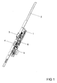
- FIG. 1 shows a drive rod lock with a longitudinally displaceably guided in a housing 1 drive rod 2 for driving a secondary lock, not shown, or other locking means.
- the espagnolette lock has a latch 3 projecting in the illustrated embodiment and a latch 4.
- the latch 4 is in the position shown in a retracted in the housing 1 position.
- the case 3 is biased out of the housing 1.
- a lock cylinder 5 and a follower 6 of the espagnolette lock are used to retract the case 3 and the bolt. 4
- FIG. 2 shows in an enlarged view of the espagnolette lock
- a transmission 7 is provided for coupling the lock cylinder 5 with the drive rod 2.
- the transmission 7 drives via a drive pinion 8 to a drive rod connection slide 9, which is positively coupled to the drive rod 2.
- the drive sprocket 8 has a partial sprocket 10 with only a portion of the circumference extending teeth 11. Immediately adjacent the Detail Malyakkranz 10 are on the circumference of the drive pinion 8 each one Projection 12, 13 arranged.
- the projections 12, 13 are wider than a tooth 11 of the partial toothed rim 10 and each have edges 15, 16 and edges 17, 18 adjoining the edges 15, 16. Further shows FIG. 3 in that flanks of the projections 12, 13 and flanks of the teeth 11 of the partial toothed ring 10 each have the same contour in the illustrated embodiment.
- the drive pinion 8 meshes with a partial toothed ring 10 a row of teeth 19 arranged on the espagnolette 9. The row of teeth 19 is delimited at each end by a pocket 20, 21.
- the pockets 20, 21 have for receiving the projections 12, 13 of the drive pinion 8 corresponding dimensions.
- the edge 17 of a projection 12 is guided in the end position espagnolette 9 to a tooth tip 23 of an outer tooth 22 of the tooth row 19 of the espagnolette 9.
- the edge 17 of the one projection 12 of the Antriebritzels 8 faces the next tooth 22 of the espagnolette 9 slide.
- a straight line extends from a pivot point 14 of the drive pinion 8 to the tooth tip 23 of the outer tooth 22 of the espagnolette 9 through the edge 17.
Landscapes
- Engineering & Computer Science (AREA)
- Mechanical Engineering (AREA)
- Transmission Devices (AREA)
- Lock And Its Accessories (AREA)
- Mechanically-Actuated Valves (AREA)
Abstract
Description
- Die Erfindung betrifft ein Treibstangenschloss mit einem längsverschieblich geführten, eine Zahnreihe aufweisenden Treibstangenanschlussschieber und mit einem antreibbaren, Zähne der Zahnreihe des Treibstangenanschlussschiebers kämmenden Antriebsritzel.
- Ein solches Treibstangenschloss ist aus der
EP 0 141 891 A1 bekannt. Bei diesem Treibstangenschloss ist ein Teilbereich des Treibstangenanschlussschiebers als Zahnstange mit den Zähnen ausgebildet. Das Antriebsritzel weist auf seinem Umfang einen Kranz Zähne auf. Damit lässt sich durch Antrieb des Antriebsritzels der Treibstangenanschlussschieber und damit eine mit dem Treibstangenanschlussschieber verbundene Treibstange komfortabel und ruckfrei verschieben. Umgekehrt lässt sich auch durch Verschiebung des Treibstangenanschlussschiebers, beispielsweise durch Antrieb der Treibstange von Hand, das Antriebsritzel drehen. Damit bietet das Treibstangenschloss keinen Schutz gegen ein unberechtigtes Verschieben der Treibstange. - Ein Treibstangenschloss mit einem selbsthemmenden Antrieb des Treibstangenanschlussschiebers ist beispielsweise aus der
EP 1 496 177 b1 bekannt. Bei diesem Treibstangenschloss hat das Antriebsritzel auf einer Stirnseite zwei hervorstehende Antriebszapfen. Die Antriebszapfen dringen zwischen hervorstehenden Nasen des Treibstangenanschlussschiebers ein. Bei einer Drehung des Antriebsritzels verschieben die Antriebszapfen die Nasen des Treibstangenanschlussschiebers. Wenn die beiden Antriebszapfen des Antriebsritzels mit den Nasen des Treibstangenanschlussschiebers fluchten, blockieren die Antriebszapfen eine Bewegung des Treibstangenanschlussschiebers. Damit kann der Treibstangenanschlussschieber nicht ohne Antrieb des Antriebsritzels verschoben werden. Der Antrieb des Treibstangenanschlussschiebers ist damit selbsthemmend gestaltet. Nachteilig bei diesem Treibstangenschloss ist jedoch, dass das Verschieben des Treibstangenanschlussschiebers durch das Antriebsritzel sehr hakelig und damit unkomfortabel ist. Beim Antrieb des Antriebsritzels müssen die Antriebszapfen zwischen die Nasen des Treibstangenanschlussschiebers eingefädelt werden. Dieser Antrieb führt bei einer kontinuierlichen Drehbewegung des Antriebsritzels zudem zu einer unkontinuierlichen Längsbewegung des Treibstangenanschlussschiebers. - Der Erfindung liegt das Problem zugrunde, ein Treibstangenschloss der eingangs genannten Art so weiter zu bilden, dass der Treibstangenanschlussschieber kontinuierlich und ruckfrei angetrieben werden kann und dass eine Verschiebung des Treibstangenanschlussschiebers aus einer Endstellung heraus ohne Antrieb des Antriebsritzels blockiert wird.
- Dieses Problem wird erfindungsgemäß dadurch gelöst, dass das Antriebsritzel einen Vorsprung mit einer hervorstehenden Kante hat und dass die Kante bei in Endstellung befindlichem Treibstangenanschlussschieber zwischen einem Zahn des Treibstangenanschlussschiebers und einem Drehpunkt des Antriebsritzels angeordnet ist.
- Durch diese Gestaltung werden bei einem versuchten Verschieben des Treibstangenanschlussschiebers ohne Antrieb des Antriebsritzels die Zähne gegen die Kante des Vorsprungs gedrückt, so dass das Antriebsritzel in Richtung ihres Drehpunktes gedrückt wird. Eine Verdrehung des Antriebsritzels durch eine Verschiebung des Treibstangenanschlussschiebers aus der Endstellung heraus ist damit blockiert. Beim Antrieb des Antriebsritzels wird die Kante des Vorsprungs aus dem Bewegungsbereich der Zähne des Treibstangenanschlussschiebers heraus bewegt. Zudem gelangen die Zähne des Teilzahnkranzes in die Zahnreihe des Treibstangenanschlussschiebers. Dies ermöglicht einen kontinuierlichen und besonders komfortablen Antrieb des Treibstangenanschlussschiebers durch ein Verdrehen des Antriebsritzels.
- Das erfindungsgemäße Treibstangenschloss ist besonders einfach aufgebaut, wenn das Antriebsritzel einen Teilzahnkranz mit sich nur über einen Teilbereich des Umfangs erstreckenden Zähnen hat, wenn der Vorsprung auf dem Umfang des Antriebsritzels unmittelbar neben dem Teilzahnkranz angeordnet ist, wenn der Vorsprung breiter ist als ein Zahn des Teilzahnkranzes, wenn der Treibstangenanschlussschieber unmittelbar neben der Zahnreihe eine Tasche mit einer dem Vorsprung entsprechenden Breite hat und wenn bei in Endstellung befindlichem Treibstangenanschlussschieber der Vorsprung ausschließlich mit einem Teilbereich in die Tasche hineinragt.
- Der Antrieb des Teilzahnkranzes bei in Endstellung befindlichem Treibstangenanschlussschieber durch den Vorsprung gestaltet sich besonders komfortabel, wenn der Vorsprung die Breite mehrerer Zähne des Teilzahnkranzes hat und wenn der Abstand des Vorsprungs von dem nächsten Zahn des Teilzahnkranzes dem Abstand mehrerer Zähne des Teilzahnkranzes entspricht. Weiterhin treibt hierdurch der Vorsprung beim Antrieb des Antriebsritzels den Treibstangenanschlussschieber derart an, dass die Zähne des Teilzahnkranzes ohne die Gefahr eines Verhakens in die Zahnreihe geführt werden. Weiterhin kann hierdurch die Tasche als einfache Zahnlücke gefertigt sein. Damit ist der Treibstangenanschlussschieber besonders einfach zu fertigen.
- Der Vorsprung weist gemäß einer anderen vorteilhaften Weiterbildung der Erfindung besonders komfortable Abrolleigenschaften auf, wenn Flanken des Vorsprungs im Wesentlichen die Form von Flanken der Zähne des Teilzahnkranzes haben. Damit wird der Treibstangenanschlussschieber beim Antrieb über das Antriebsritzel an jeder Stelle besonders ruckfrei angetrieben. Ebenso können die Flanken des Vorsprungs mit den Werkzeugen gefertigt werden, mit denen die Zähne des Teilzahnkranzes bearbeitet werden. Dies trägt zur Verringerung der Fertigungskosten des erfindungsgemäßen Treibstangenschlosses bei.
- Das Antriebsritzel lässt sich gemäß einer anderen vorteilhaften Weiterbildung der Erfindung besonders komfortabel fertigen, wenn die Kante am freien Ende des Vorsprungs bogenförmig gestaltet ist und bei in Endstellung befindlichem Treibstangenanschlussschieber bis über eine Zahnspitze des äußeren Zahnes der Zahnreihe des Treibstangenanschlussschiebers geführt ist. Hierdurch steht der Vorsprung bei in Endstellung befindlichem Treibstangenanschlussschieber mit der Kante dem äußeren Zahn der Zahnreihe des Treibstangenanschlussschiebers gegenüber. Damit wird eine Bewegung des Treibstangenanschlussschiebers blockiert.
- Der Antrieb des Treibstangenanschlussschiebers ist gemäß einer anderen vorteilhaften Weiterbildung der Erfindung in beiden Endstellungen selbsthemmend gestaltet, wenn zu beiden Seiten der Zahnreihe jeweils eine Tasche und zu beiden Seiten des Teilzahnkranzes jeweils ein Vorsprung angeordnet ist.
- Die Erfindung lässt zahlreiche Ausführungsformen zu. Zur weiteren Verdeutlichung ihres Grundprinzips ist eine davon in der Zeichnung dargestellt und wird nachfolgend beschrieben. Diese zeigt in
- Fig. 1
- perspektivisch ein erfindungsgemäßes Treibstangenschloss mit einem Nebenschloss,
- Fig. 2
- vergrößert eine Draufsicht auf das Treibstangenschloss aus
Figur 1 , - Fig. 3
- stark vergrößert einen Treibstangenanschlussschieber mit einem Antriebsritzel des Treibstangenschlosses aus
Figur 1 . -
Figur 1 zeigt ein Treibstangenschloss mit einer in einem Gehäuse 1 längsverschieblich geführten Treibstange 2 zum Antrieb eines nicht dargestellten Nebenschlosses oder weiterer Verriegelungsmittel. Das Treibstangenschloss weist eine in der dargestellten Ausführungsform hervorstehende Falle 3 und einen Riegel 4 auf. Der Riegel 4 befindet sich in der dargestellten Stellung in einer in dem Gehäuse 1 zurückgezogen Position. Die Falle 3 ist aus dem Gehäuse 1 heraus vorgespannt. Ein Schließzylinder 5 und eine Drückernuss 6 des Treibstangenschlosses dienen zum Zurückziehen der Falle 3 und des Riegels 4. - Wie
Figur 2 in einer vergrößerten Darstellung auf das Treibstangenschloss zeigt, ist zur Koppelung des Schließzylinders 5 mit der Treibstange 2 ein Getriebe 7 vorgesehen. Zur Vereinfachung der Zeichnung ist inFigur 2 das Treibstangenschloss geöffnet dargestellt, so dass das Getriebe 7 sichtbar ist. Das Getriebe 7 treibt über ein Antriebsritzel 8 einen Treibstangenanschlussschieber 9 an, welcher formschlüssig mit der Treibstange 2 gekoppelt ist. -
Figur 3 zeigt stark vergrößert das Antriebsritzel 8 mit dem Treibstangenanschlussschieber 9 nahe einer Endstellung des Treibstangenanschlussschiebers 9. Das Antriebsritzel 8 hat einen Teilzahnkranz 10 mit sich nur über einen Teilbereich des Umfangs erstreckenden Zähnen 11. Unmittelbar neben dem Teilzahnkranz 10 sind auf dem Umfang des Antriebsritzels 8 jeweils ein Vorsprung 12, 13 angeordnet. Die Vorsprünge 12, 13 sind breiter als ein Zahn 11 des Teilzahnkranzes 10 und weisen jeweils Ränder 15, 16 und sich an die Ränder 15, 16 anschließenden Kanten 17, 18 auf. Weiterhin zeigtFigur 3 , dass Flanken der Vorsprünge 12, 13 und Flanken der Zähne 11 des Teilzahnkranzes 10 in der dargestellten Ausführungsform jeweils die gleiche Kontur haben. Das Antriebsritzel 8 kämmt mit einem Teilzahnkranz 10 eine auf dem Treibstangenanschlussschieber 9 angeordnete Zahnreihe 19. Die Zahnreihe 19 ist zu beiden Enden jeweils von einer Tasche 20, 21 begrenzt. Die Taschen 20, 21 weisen zur Aufnahme der Vorsprünge 12, 13 des Antriebsritzels 8 entsprechende Abmessungen auf. - In der dargestellten Endstellung des Treibstangenanschlussschiebers 9 liegt einer der Vorsprünge 12 in einer der Taschen 20. Die Kante 17 des einen Vorsprungs 12 ist bei dem in Endstellung befindlichen Treibstangenanschlussschieber 9 bis über eine Zahnspitze 23 eines äußeren Zahns 22 der Zahnreihe 19 des Treibstangenanschlussschiebers 9 geführt. Damit steht die Kante 17 des einen Vorsprungs 12 des Antriebritzels 8 dem nächsten Zahn 22 des Treibstangenanschlussschiebers 9 gegenüber. Dabei verläuft eine Gerade von einem Drehpunkt 14 des Antriebsritzels 8 zu der Zahnspitze 23 des äußeren Zahns 22 des Treibstangenanschlussschiebers 9 durch die Kante 17.
- Bei einem Antrieb des Antriebsritzels 8 mittels des Schließzylinders 5 aus
Figur 1 wird der Treibstangenanschlussschieber 9 und damit die Treibstange 2 verschoben. Wird jedoch ausgehend von der Endstellung der Treibstangenanschlussschieber 9 verschoben, gelangt die Zahnspitze 23 des äußersten Zahns 22 der Zahnreihe 19 des Treibstangenanschlussschiebers 9 gegen die Kante 17 des Vorsprungs 12 des Antriebsritzels 8 und übt eine in Richtung Drehpunkt 14 des Antriebsritzels 8 wirkende Kraft auf den Vorsprung 12 auf. Dabei blockiert das Antriebsritzel 8 die weitere Bewegung des Treibstangenanschlussschiebers 9. - Die Bewegung des Antriebsritzels 8 beim Antrieb durch das in
Figur 2 dargestellte Getriebe wird begrenzt, wenn ein Anschlag 24 des Antriebsritzels 8 gegen einen Anschlag 25 des Treibstangenanschlussschiebers 9 gelangt. Damit lässt sich das Getriebe 7 bei in Endstellung befindlichem Treibstangenanschlussschieber 9 weiter bewegen, um die Falle 3 in das Gehäuse 1 zurückzuziehen.
Claims (6)
- Treibstangenschloss mit einem längsverschieblich geführten, eine Zahnreihe aufweisenden Treibstangenanschlussschieber und mit einem antreibbaren, Zähne der Zahnreihe des Treibstangenanschlussschiebers kämmenden Antriebsritzel, dadurch gekennzeichnet, dass das Antriebsritzel (8) einen Vorsprung (12, 13) mit einer hervorstehenden Kante (17, 18) hat und dass die Kante (17, 18) bei in Endstellung befindlichem Treibstangenanschlussschieber (9) zwischen einem Zahn (22) des Treibstangenanschlussschiebers (9) und einem Drehpunkt (14) des Antriebsritzels (8) angeordnet ist.
- Treibstangenschloss nach Anspruch 1, dadurch gekennzeichnet, dass das Antriebsritzel (8) einen Teilzahnkranz (10) mit sich nur über einen Teilbereich des Umfangs erstreckenden Zähnen (11) hat, dass der Vorsprung (12, 13) auf dem Umfang des Antriebsritzels (8) unmittelbar neben dem Teilzahnkranz (10) angeordnet ist, dass der Vorsprung (12, 13) breiter ist als ein Zahn (11) des Teilzahnkranzes (10), dass der Treibstangenanschlussschieber (9) unmittelbar neben der Zahnreihe (19) eine Tasche (20, 21) mit einer dem Vorsprung (12, 13) entsprechenden Breite hat und dass bei in Endstellung befindlichem Treibstangenanschlussschieber (9) der Vorsprung (12, 13) ausschließlich mit einem Teilbereich in die Tasche (20, 21) hineinragt.
- Treibstangenschloss nach Anspruch 1 oder 2, dadurch gekennzeichnet, dass der Vorsprung (12, 13) die Breite mehrerer Zähne (11) des Teilzahnkranzes (10) hat und dass der Abstand des Vorsprungs (12, 13) von dem nächsten Zahn (11) des Teilzahnkranzes (10) dem Abstand mehrerer Zähne (11) des Teilzahnkranzes (10) entspricht.
- Treibstangenschloss nach einem der vorhergehenden Ansprüchen, dadurch gekennzeichnet, dass Flanken des Vorsprungs (12, 13) im Wesentlichen die Form von Flanken der Zähne (11) des Teilzahnkranzes (10) haben.
- Treibstangenschloss nach einem der vorhergehenden Ansprüchen, dadurch gekennzeichnet, dass die Kante (17, 18) am freien Ende des Vorsprungs (12, 13) bogenförmig gestaltet ist und bei in Endstellung befindlichem Treibstangenanschlussschieber (9) bis über eine Zahnspitze (23) des äußeren Zahnes (22) der Zahnreihe (19) des Treibstangenanschlussschiebers (9) geführt ist.
- Treibstangenschloss nach einem der vorhergehenden Ansprüchen, dadurch gekennzeichnet, dass zu beiden Seiten der Zahnreihe (19) jeweils eine Tasche (20, 21) und zu beiden Seiten des Teilzahnkranzes (10) jeweils ein Vorsprung (12, 13) angeordnet ist.
Applications Claiming Priority (1)
| Application Number | Priority Date | Filing Date | Title |
|---|---|---|---|
| DE102008001115A DE102008001115A1 (de) | 2008-04-10 | 2008-04-10 | Treibstangenschloss |
Publications (3)
| Publication Number | Publication Date |
|---|---|
| EP2108771A2 true EP2108771A2 (de) | 2009-10-14 |
| EP2108771A3 EP2108771A3 (de) | 2011-07-20 |
| EP2108771B1 EP2108771B1 (de) | 2012-05-16 |
Family
ID=40785599
Family Applications (1)
| Application Number | Title | Priority Date | Filing Date |
|---|---|---|---|
| EP20090154456 Active EP2108771B1 (de) | 2008-04-10 | 2009-03-05 | Treibstangenschloss |
Country Status (2)
| Country | Link |
|---|---|
| EP (1) | EP2108771B1 (de) |
| DE (1) | DE102008001115A1 (de) |
Citations (2)
| Publication number | Priority date | Publication date | Assignee | Title |
|---|---|---|---|---|
| EP0141891A1 (de) | 1983-11-09 | 1985-05-22 | FERCO INTERNATIONAL Usine de Ferrures de BÀ¢timent Société à responsabilité limitée | Treibstangenschloss für Türen, Fenstertüren oder dgl. |
| EP1496177B1 (de) | 2003-07-10 | 2006-08-02 | Roto Frank Ag | Schlüsselbetätigbares Mehrriegelschloss |
Family Cites Families (3)
| Publication number | Priority date | Publication date | Assignee | Title |
|---|---|---|---|---|
| DE8915376U1 (de) * | 1988-01-18 | 1990-07-05 | Aug. Winkhaus GmbH & Co KG, 4404 Telgte | Treibstangenschloß |
| DE10259278A1 (de) * | 2002-12-17 | 2004-07-08 | Niemann, Hans Dieter | Leistenverriegelung |
| DE10359803A1 (de) * | 2003-12-19 | 2005-07-14 | Aug. Winkhaus Gmbh & Co. Kg | Treibstangenschloss |
-
2008
- 2008-04-10 DE DE102008001115A patent/DE102008001115A1/de not_active Withdrawn
-
2009
- 2009-03-05 EP EP20090154456 patent/EP2108771B1/de active Active
Patent Citations (2)
| Publication number | Priority date | Publication date | Assignee | Title |
|---|---|---|---|---|
| EP0141891A1 (de) | 1983-11-09 | 1985-05-22 | FERCO INTERNATIONAL Usine de Ferrures de BÀ¢timent Société à responsabilité limitée | Treibstangenschloss für Türen, Fenstertüren oder dgl. |
| EP1496177B1 (de) | 2003-07-10 | 2006-08-02 | Roto Frank Ag | Schlüsselbetätigbares Mehrriegelschloss |
Also Published As
| Publication number | Publication date |
|---|---|
| EP2108771B1 (de) | 2012-05-16 |
| EP2108771A3 (de) | 2011-07-20 |
| DE102008001115A1 (de) | 2009-10-15 |
Similar Documents
| Publication | Publication Date | Title |
|---|---|---|
| DE69920530T3 (de) | Schlüssel für ein Zylinderschloss | |
| EP1867817B1 (de) | Treibstangenverschluss | |
| DE102006025383B3 (de) | Bordmonitoreinrichtung | |
| EP2261445B1 (de) | Schloss, insbesondere Türschloss, mit verbesserter Schließmechanik | |
| DE102009030032A1 (de) | Plättchenzylinder mit sperrbaren Plättchenzuhaltungen | |
| EP2108771B1 (de) | Treibstangenschloss | |
| EP1518985A1 (de) | Getriebe, insbesondere Schlagleistengetriebe für ein Fenster oder dergleichen | |
| DE102008009511B4 (de) | Schloss mit einer verbesserten Schließmechanik | |
| DE10100787A1 (de) | Schliesszylinder | |
| EP2458120A2 (de) | Verschluss eines Treibstangenbeschlages | |
| DE102008016319A1 (de) | Schloss mit einer Sicherheitseinrichtung | |
| EP1806466A2 (de) | Zylinderschloss mit Schieber sowie Flachschlüssel mit Steuerrippe | |
| DE202006003869U1 (de) | Zylinderschloss und Flachschlüssel | |
| EP2186975B1 (de) | Schlüssel für einen Schließzylinder | |
| EP2096244B1 (de) | Beschlag für ein Fenster, eine Tür oder dergleichen | |
| WO2006116973A1 (de) | Kartenleser mit verriegelung | |
| DE102013226726B4 (de) | Verriegelungsvorrichtung mit einer motorisch angetriebenen Verriegelungskulisse | |
| EP1452676B1 (de) | Getriebe für ein Fenster oder dergleichen mit integrierter Rastung, insbesondere Spreizgetriebe | |
| EP2108769B1 (de) | Einsteckschloss | |
| EP3498942A1 (de) | Schloss | |
| EP3521538B1 (de) | Schloss mit einem fallenriegel | |
| DE102006000124A1 (de) | Schloss | |
| EP3486409B1 (de) | Fehlschaltsicherung für einen treibstangenbeschlag | |
| EP3412849B1 (de) | Schlüssel für einen schliesszylinder und schliesszylinder für einen solchen schlüssel | |
| EP2405084B1 (de) | Schloss |
Legal Events
| Date | Code | Title | Description |
|---|---|---|---|
| PUAI | Public reference made under article 153(3) epc to a published international application that has entered the european phase |
Free format text: ORIGINAL CODE: 0009012 |
|
| AK | Designated contracting states |
Kind code of ref document: A2 Designated state(s): AT BE BG CH CY CZ DE DK EE ES FI FR GB GR HR HU IE IS IT LI LT LU LV MC MK MT NL NO PL PT RO SE SI SK TR |
|
| AX | Request for extension of the european patent |
Extension state: AL BA RS |
|
| PUAL | Search report despatched |
Free format text: ORIGINAL CODE: 0009013 |
|
| AK | Designated contracting states |
Kind code of ref document: A3 Designated state(s): AT BE BG CH CY CZ DE DK EE ES FI FR GB GR HR HU IE IS IT LI LT LU LV MC MK MT NL NO PL PT RO SE SI SK TR |
|
| AX | Request for extension of the european patent |
Extension state: AL BA RS |
|
| GRAP | Despatch of communication of intention to grant a patent |
Free format text: ORIGINAL CODE: EPIDOSNIGR1 |
|
| 17P | Request for examination filed |
Effective date: 20111018 |
|
| GRAS | Grant fee paid |
Free format text: ORIGINAL CODE: EPIDOSNIGR3 |
|
| AKX | Designation fees paid |
Designated state(s): AT BE BG CH CY CZ DE DK EE ES FI FR GB GR HR HU IE IS IT LI LT LU LV MC MK MT NL NO PL PT RO SE SI SK TR |
|
| GRAA | (expected) grant |
Free format text: ORIGINAL CODE: 0009210 |
|
| AK | Designated contracting states |
Kind code of ref document: B1 Designated state(s): AT BE BG CH CY CZ DE DK EE ES FI FR GB GR HR HU IE IS IT LI LT LU LV MC MK MT NL NO PL PT RO SE SI SK TR |
|
| REG | Reference to a national code |
Ref country code: GB Ref legal event code: FG4D Free format text: NOT ENGLISH |
|
| REG | Reference to a national code |
Ref country code: CH Ref legal event code: EP |
|
| REG | Reference to a national code |
Ref country code: AT Ref legal event code: REF Ref document number: 558192 Country of ref document: AT Kind code of ref document: T Effective date: 20120615 |
|
| REG | Reference to a national code |
Ref country code: IE Ref legal event code: FG4D Free format text: LANGUAGE OF EP DOCUMENT: GERMAN |
|
| REG | Reference to a national code |
Ref country code: DE Ref legal event code: R096 Ref document number: 502009003533 Country of ref document: DE Effective date: 20120712 |
|
| REG | Reference to a national code |
Ref country code: NL Ref legal event code: VDEP Effective date: 20120516 |
|
| REG | Reference to a national code |
Ref country code: LT Ref legal event code: MG4D Effective date: 20120516 |
|
| PG25 | Lapsed in a contracting state [announced via postgrant information from national office to epo] |
Ref country code: PL Free format text: LAPSE BECAUSE OF FAILURE TO SUBMIT A TRANSLATION OF THE DESCRIPTION OR TO PAY THE FEE WITHIN THE PRESCRIBED TIME-LIMIT Effective date: 20120516 Ref country code: FI Free format text: LAPSE BECAUSE OF FAILURE TO SUBMIT A TRANSLATION OF THE DESCRIPTION OR TO PAY THE FEE WITHIN THE PRESCRIBED TIME-LIMIT Effective date: 20120516 Ref country code: CY Free format text: LAPSE BECAUSE OF FAILURE TO SUBMIT A TRANSLATION OF THE DESCRIPTION OR TO PAY THE FEE WITHIN THE PRESCRIBED TIME-LIMIT Effective date: 20120516 Ref country code: SE Free format text: LAPSE BECAUSE OF FAILURE TO SUBMIT A TRANSLATION OF THE DESCRIPTION OR TO PAY THE FEE WITHIN THE PRESCRIBED TIME-LIMIT Effective date: 20120516 Ref country code: NO Free format text: LAPSE BECAUSE OF FAILURE TO SUBMIT A TRANSLATION OF THE DESCRIPTION OR TO PAY THE FEE WITHIN THE PRESCRIBED TIME-LIMIT Effective date: 20120816 Ref country code: LT Free format text: LAPSE BECAUSE OF FAILURE TO SUBMIT A TRANSLATION OF THE DESCRIPTION OR TO PAY THE FEE WITHIN THE PRESCRIBED TIME-LIMIT Effective date: 20120516 Ref country code: IS Free format text: LAPSE BECAUSE OF FAILURE TO SUBMIT A TRANSLATION OF THE DESCRIPTION OR TO PAY THE FEE WITHIN THE PRESCRIBED TIME-LIMIT Effective date: 20120916 |
|
| PG25 | Lapsed in a contracting state [announced via postgrant information from national office to epo] |
Ref country code: HR Free format text: LAPSE BECAUSE OF FAILURE TO SUBMIT A TRANSLATION OF THE DESCRIPTION OR TO PAY THE FEE WITHIN THE PRESCRIBED TIME-LIMIT Effective date: 20120516 Ref country code: PT Free format text: LAPSE BECAUSE OF FAILURE TO SUBMIT A TRANSLATION OF THE DESCRIPTION OR TO PAY THE FEE WITHIN THE PRESCRIBED TIME-LIMIT Effective date: 20120917 Ref country code: LV Free format text: LAPSE BECAUSE OF FAILURE TO SUBMIT A TRANSLATION OF THE DESCRIPTION OR TO PAY THE FEE WITHIN THE PRESCRIBED TIME-LIMIT Effective date: 20120516 Ref country code: SI Free format text: LAPSE BECAUSE OF FAILURE TO SUBMIT A TRANSLATION OF THE DESCRIPTION OR TO PAY THE FEE WITHIN THE PRESCRIBED TIME-LIMIT Effective date: 20120516 Ref country code: GR Free format text: LAPSE BECAUSE OF FAILURE TO SUBMIT A TRANSLATION OF THE DESCRIPTION OR TO PAY THE FEE WITHIN THE PRESCRIBED TIME-LIMIT Effective date: 20120817 |
|
| PG25 | Lapsed in a contracting state [announced via postgrant information from national office to epo] |
Ref country code: CZ Free format text: LAPSE BECAUSE OF FAILURE TO SUBMIT A TRANSLATION OF THE DESCRIPTION OR TO PAY THE FEE WITHIN THE PRESCRIBED TIME-LIMIT Effective date: 20120516 Ref country code: DK Free format text: LAPSE BECAUSE OF FAILURE TO SUBMIT A TRANSLATION OF THE DESCRIPTION OR TO PAY THE FEE WITHIN THE PRESCRIBED TIME-LIMIT Effective date: 20120516 Ref country code: SK Free format text: LAPSE BECAUSE OF FAILURE TO SUBMIT A TRANSLATION OF THE DESCRIPTION OR TO PAY THE FEE WITHIN THE PRESCRIBED TIME-LIMIT Effective date: 20120516 Ref country code: NL Free format text: LAPSE BECAUSE OF FAILURE TO SUBMIT A TRANSLATION OF THE DESCRIPTION OR TO PAY THE FEE WITHIN THE PRESCRIBED TIME-LIMIT Effective date: 20120516 Ref country code: RO Free format text: LAPSE BECAUSE OF FAILURE TO SUBMIT A TRANSLATION OF THE DESCRIPTION OR TO PAY THE FEE WITHIN THE PRESCRIBED TIME-LIMIT Effective date: 20120516 Ref country code: EE Free format text: LAPSE BECAUSE OF FAILURE TO SUBMIT A TRANSLATION OF THE DESCRIPTION OR TO PAY THE FEE WITHIN THE PRESCRIBED TIME-LIMIT Effective date: 20120516 |
|
| PG25 | Lapsed in a contracting state [announced via postgrant information from national office to epo] |
Ref country code: IT Free format text: LAPSE BECAUSE OF FAILURE TO SUBMIT A TRANSLATION OF THE DESCRIPTION OR TO PAY THE FEE WITHIN THE PRESCRIBED TIME-LIMIT Effective date: 20120516 |
|
| PLBE | No opposition filed within time limit |
Free format text: ORIGINAL CODE: 0009261 |
|
| STAA | Information on the status of an ep patent application or granted ep patent |
Free format text: STATUS: NO OPPOSITION FILED WITHIN TIME LIMIT |
|
| 26N | No opposition filed |
Effective date: 20130219 |
|
| PG25 | Lapsed in a contracting state [announced via postgrant information from national office to epo] |
Ref country code: ES Free format text: LAPSE BECAUSE OF FAILURE TO SUBMIT A TRANSLATION OF THE DESCRIPTION OR TO PAY THE FEE WITHIN THE PRESCRIBED TIME-LIMIT Effective date: 20120827 |
|
| REG | Reference to a national code |
Ref country code: DE Ref legal event code: R097 Ref document number: 502009003533 Country of ref document: DE Effective date: 20130219 |
|
| PG25 | Lapsed in a contracting state [announced via postgrant information from national office to epo] |
Ref country code: BG Free format text: LAPSE BECAUSE OF FAILURE TO SUBMIT A TRANSLATION OF THE DESCRIPTION OR TO PAY THE FEE WITHIN THE PRESCRIBED TIME-LIMIT Effective date: 20120816 |
|
| BERE | Be: lapsed |
Owner name: AUG. WINKHAUS G.M.B.H. & CO. KG Effective date: 20130331 |
|
| PG25 | Lapsed in a contracting state [announced via postgrant information from national office to epo] |
Ref country code: MC Free format text: LAPSE BECAUSE OF NON-PAYMENT OF DUE FEES Effective date: 20130331 |
|
| REG | Reference to a national code |
Ref country code: CH Ref legal event code: PL |
|
| REG | Reference to a national code |
Ref country code: IE Ref legal event code: MM4A |
|
| PG25 | Lapsed in a contracting state [announced via postgrant information from national office to epo] |
Ref country code: BE Free format text: LAPSE BECAUSE OF NON-PAYMENT OF DUE FEES Effective date: 20130331 Ref country code: CH Free format text: LAPSE BECAUSE OF NON-PAYMENT OF DUE FEES Effective date: 20130331 Ref country code: LI Free format text: LAPSE BECAUSE OF NON-PAYMENT OF DUE FEES Effective date: 20130331 Ref country code: IE Free format text: LAPSE BECAUSE OF NON-PAYMENT OF DUE FEES Effective date: 20130305 |
|
| PG25 | Lapsed in a contracting state [announced via postgrant information from national office to epo] |
Ref country code: MT Free format text: LAPSE BECAUSE OF FAILURE TO SUBMIT A TRANSLATION OF THE DESCRIPTION OR TO PAY THE FEE WITHIN THE PRESCRIBED TIME-LIMIT Effective date: 20120516 |
|
| PG25 | Lapsed in a contracting state [announced via postgrant information from national office to epo] |
Ref country code: TR Free format text: LAPSE BECAUSE OF FAILURE TO SUBMIT A TRANSLATION OF THE DESCRIPTION OR TO PAY THE FEE WITHIN THE PRESCRIBED TIME-LIMIT Effective date: 20120516 |
|
| PG25 | Lapsed in a contracting state [announced via postgrant information from national office to epo] |
Ref country code: MK Free format text: LAPSE BECAUSE OF FAILURE TO SUBMIT A TRANSLATION OF THE DESCRIPTION OR TO PAY THE FEE WITHIN THE PRESCRIBED TIME-LIMIT Effective date: 20120516 Ref country code: LU Free format text: LAPSE BECAUSE OF NON-PAYMENT OF DUE FEES Effective date: 20130305 Ref country code: HU Free format text: LAPSE BECAUSE OF FAILURE TO SUBMIT A TRANSLATION OF THE DESCRIPTION OR TO PAY THE FEE WITHIN THE PRESCRIBED TIME-LIMIT; INVALID AB INITIO Effective date: 20090305 |
|
| REG | Reference to a national code |
Ref country code: FR Ref legal event code: PLFP Year of fee payment: 8 |
|
| REG | Reference to a national code |
Ref country code: FR Ref legal event code: PLFP Year of fee payment: 9 |
|
| PGFP | Annual fee paid to national office [announced via postgrant information from national office to epo] |
Ref country code: GB Payment date: 20170330 Year of fee payment: 9 |
|
| REG | Reference to a national code |
Ref country code: FR Ref legal event code: PLFP Year of fee payment: 10 |
|
| GBPC | Gb: european patent ceased through non-payment of renewal fee |
Effective date: 20180305 |
|
| PG25 | Lapsed in a contracting state [announced via postgrant information from national office to epo] |
Ref country code: GB Free format text: LAPSE BECAUSE OF NON-PAYMENT OF DUE FEES Effective date: 20180305 |
|
| PGFP | Annual fee paid to national office [announced via postgrant information from national office to epo] |
Ref country code: AT Payment date: 20220318 Year of fee payment: 14 |
|
| PGFP | Annual fee paid to national office [announced via postgrant information from national office to epo] |
Ref country code: FR Payment date: 20230320 Year of fee payment: 15 |
|
| P01 | Opt-out of the competence of the unified patent court (upc) registered |
Effective date: 20230512 |
|
| REG | Reference to a national code |
Ref country code: AT Ref legal event code: MM01 Ref document number: 558192 Country of ref document: AT Kind code of ref document: T Effective date: 20230305 |
|
| PG25 | Lapsed in a contracting state [announced via postgrant information from national office to epo] |
Ref country code: AT Free format text: LAPSE BECAUSE OF NON-PAYMENT OF DUE FEES Effective date: 20230305 |
|
| REG | Reference to a national code |
Ref country code: DE Ref legal event code: R081 Ref document number: 502009003533 Country of ref document: DE Owner name: AUG. WINKHAUS SE & CO. KG, DE Free format text: FORMER OWNER: AUG. WINKHAUS GMBH & CO. KG, 48291 TELGTE, DE Ref country code: DE Ref legal event code: R081 Ref document number: 502009003533 Country of ref document: DE Owner name: AUG. WINKHAUS SE, DE Free format text: FORMER OWNER: AUG. WINKHAUS GMBH & CO. KG, 48291 TELGTE, DE |
|
| PG25 | Lapsed in a contracting state [announced via postgrant information from national office to epo] |
Ref country code: FR Free format text: LAPSE BECAUSE OF NON-PAYMENT OF DUE FEES Effective date: 20240331 |
|
| PG25 | Lapsed in a contracting state [announced via postgrant information from national office to epo] |
Ref country code: FR Free format text: LAPSE BECAUSE OF NON-PAYMENT OF DUE FEES Effective date: 20240331 |
|
| PGFP | Annual fee paid to national office [announced via postgrant information from national office to epo] |
Ref country code: DE Payment date: 20250319 Year of fee payment: 17 |
|
| REG | Reference to a national code |
Ref country code: DE Ref legal event code: R081 Ref document number: 502009003533 Country of ref document: DE Owner name: AUG. WINKHAUS SE, DE Free format text: FORMER OWNER: AUG. WINKHAUS SE & CO. KG, 48291 TELGTE, DE |