EP2108481A2 - Procédé et appareil de traitement - Google Patents
Procédé et appareil de traitement Download PDFInfo
- Publication number
- EP2108481A2 EP2108481A2 EP09005175A EP09005175A EP2108481A2 EP 2108481 A2 EP2108481 A2 EP 2108481A2 EP 09005175 A EP09005175 A EP 09005175A EP 09005175 A EP09005175 A EP 09005175A EP 2108481 A2 EP2108481 A2 EP 2108481A2
- Authority
- EP
- European Patent Office
- Prior art keywords
- drive motor
- rotation
- drive
- axis
- container
- Prior art date
- Legal status (The legal status is an assumption and is not a legal conclusion. Google has not performed a legal analysis and makes no representation as to the accuracy of the status listed.)
- Granted
Links
Images


Classifications
-
- B—PERFORMING OPERATIONS; TRANSPORTING
- B24—GRINDING; POLISHING
- B24B—MACHINES, DEVICES, OR PROCESSES FOR GRINDING OR POLISHING; DRESSING OR CONDITIONING OF ABRADING SURFACES; FEEDING OF GRINDING, POLISHING, OR LAPPING AGENTS
- B24B31/00—Machines or devices designed for polishing or abrading surfaces on work by means of tumbling apparatus or other apparatus in which the work and/or the abrasive material is loose; Accessories therefor
- B24B31/003—Machines or devices designed for polishing or abrading surfaces on work by means of tumbling apparatus or other apparatus in which the work and/or the abrasive material is loose; Accessories therefor whereby the workpieces are mounted on a holder and are immersed in the abrasive material
-
- B—PERFORMING OPERATIONS; TRANSPORTING
- B24—GRINDING; POLISHING
- B24B—MACHINES, DEVICES, OR PROCESSES FOR GRINDING OR POLISHING; DRESSING OR CONDITIONING OF ABRADING SURFACES; FEEDING OF GRINDING, POLISHING, OR LAPPING AGENTS
- B24B47/00—Drives or gearings; Equipment therefor
- B24B47/10—Drives or gearings; Equipment therefor for rotating or reciprocating working-spindles carrying grinding wheels or workpieces
-
- Y—GENERAL TAGGING OF NEW TECHNOLOGICAL DEVELOPMENTS; GENERAL TAGGING OF CROSS-SECTIONAL TECHNOLOGIES SPANNING OVER SEVERAL SECTIONS OF THE IPC; TECHNICAL SUBJECTS COVERED BY FORMER USPC CROSS-REFERENCE ART COLLECTIONS [XRACs] AND DIGESTS
- Y10—TECHNICAL SUBJECTS COVERED BY FORMER USPC
- Y10T—TECHNICAL SUBJECTS COVERED BY FORMER US CLASSIFICATION
- Y10T29/00—Metal working
- Y10T29/49—Method of mechanical manufacture
- Y10T29/49481—Wheel making
- Y10T29/49492—Land wheel
- Y10T29/49524—Rim making
-
- Y—GENERAL TAGGING OF NEW TECHNOLOGICAL DEVELOPMENTS; GENERAL TAGGING OF CROSS-SECTIONAL TECHNOLOGIES SPANNING OVER SEVERAL SECTIONS OF THE IPC; TECHNICAL SUBJECTS COVERED BY FORMER USPC CROSS-REFERENCE ART COLLECTIONS [XRACs] AND DIGESTS
- Y10—TECHNICAL SUBJECTS COVERED BY FORMER USPC
- Y10T—TECHNICAL SUBJECTS COVERED BY FORMER US CLASSIFICATION
- Y10T29/00—Metal working
- Y10T29/53—Means to assemble or disassemble
- Y10T29/53448—Vehicle wheel
Definitions
- the present invention relates to a method of machining particularly rotationally symmetrical workpieces, e.g. Vehicle rims.
- the workpiece is simultaneously rotated by a first drive motor about its own vertical central axis, it is moved by a second drive motor with its central axis along an orbital motion along a closed orbit about a rotating vertical axis and this vertical axis is by means of a third Drive motor rotated about a stationary vertical axis of rotation.
- a third Drive motor rotated about a stationary vertical axis of rotation.
- the orbital movement and the rotational movement of the workpiece is accomplished by means of two separate drive motors, whereby these two drives are independently controlled separately and are no longer firmly coupled.
- a plurality of workpieces may be dipped into the container and moved relative to the container, all workpieces being rotated about their own vertical center axis, about the rotating vertical axis and about the stationary vertical axis of rotation.
- this method there is the advantage that any processing shadows are minimized, since each workpiece is rotated about its own central axis and thus no part of the workpiece rotates on a circular path, on which the part is always directed to the center of this circular path.
- the workpiece can be moved in a rotational direction along the closed orbit, wherein the workpiece is moved in the opposite direction of rotation about its own central axis.
- none of the drive motors is subjected to a rotary or orbital movement. This contributes to a long life of the device, since the two drive motors need only be subjected to the oscillatory movement, which, however, takes place at a comparatively low speed.
- a wobbling motion can additionally be imposed on the workpiece in order to further increase the relative movement between the processing means and the workpiece.
- the two drive motors are mounted on a component which is either stationary, for example, when the processing agent container is oscillated, or which is oscillatable by an oscillating device.
- the two electric motors no quick rotational movements but only a comparatively slow oscillatory motion are subjected.
- the orbital drive to a rotatably driven by a drive motor component on which the chuck is eccentrically and rotatably mounted.
- the chuck which rotates along the orbital path, can rotate about its own axis with a drive motor that does not orbit itself along the orbital path, but remains stationary compared to the movement of the workpiece.
- the rotation device it may be advantageous for the rotation device to have a shaft which is rotatably driven by the other drive motor and which extends through the component and which is in rotary connection with the chuck.
- a third drive motor can be provided, with which the vertical axis is rotatable about a stationary vertical axis of rotation, so that on the one hand rotates the workpiece about its own central axis and on the other hand rotates the workpiece on an orbital path and to the stationary vertical axis of rotation rotates.
- the rotation means may comprise a plurality of chucks which can be rotated about their own central axis either via a common transmission, for example a planetary gear, or via their own drive.
- the chucks are arranged coaxially with each other and on the one hand about their own axis of rotation, on the other hand rotated about the rotating axis of rotation and finally also about the stationary axis of rotation, whereby best machining results are achieved.
- inventive method is basically suitable for all workpieces and in particular for rotationally symmetrical workpieces.
- rims all kinds of rims or wheels, i. Rims for cars, trucks or motorcycles in all sizes and variations.
- the machining may be deburring, descaling, rounding, grinding, polishing or the like.
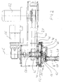
- the processing device shown has a base frame 10, on which a processing agent container 12 is arranged.
- the processing agent container 12 is formed in the illustrated embodiment, round and open at the top, but may also be trough-shaped or trough-shaped.
- the processing agent container 12 is not in any fixed connection with the base frame 10 and can thus be easily replaced by industrial trucks.
- a vibration drive may additionally be provided.
- various supply and discharge possibilities are provided on the processing medium container 12 in order to continuously add or remove water and / or treatment agents (compounds). In operation, the container 12 is filled to about the level of level N with processing means.
- a stirring element 14 is provided, which has a plurality of parallel to the bottom extending paddle, which is driven by a drive 16, which is located below the container bottom, about a vertical axis of rotation D rotating.
- a machine stand 18 is arranged on the base frame 10, on which a cross-beam 20 in the vertical direction, that is along the double arrow X, slidably mounted.
- the vertical movement is effected via a drive 22, not shown, which causes a raising and lowering of the cross-beam 20 in conjunction with a lifting cylinder 24.
- the crossbeam along the axis A raised or lowered in the direction of the double arrow X.
- the cross-beam 20 When in the Fig. 1 shown position, the cross-beam 20 is in an upper position corresponding to the loading and unloading position, that is, from the position shown, the cross-beam 20 can be moved down.
- a chuck 28 is mounted at the lower end of a shaft 26 guided in a shaft, which serves for fastening a workpiece, such as a rim F.
- the shaft 27 is in this case attached to a transmission 30, which in Fig. 2 is shown enlarged.
- Fig. 2 clarified, is on the crossbeam 20 at her in Fig. 2 mounted on the right end of a first drive motor 32, whose axis of rotation is vertical and which drives a arranged in the cross-beam 20 belt drive 40, a hollow shaft 42 which rotates about a vertical axis of rotation C.
- the hollow shaft 42 extends down through the crossbar 20 and further through a two-piece turntable 44, the upper half 46 is screwed to the crossbeam 20 and the lower half 48 is rotatable about a ball bearing 46 relative to the upper half.
- the hollow shaft 42 is screwed at its lower end to the lower half 48 of the turntable 44, so that upon rotation of the hollow shaft 42 about the axis C, the lower half 48 of the turntable 44 rotates together with the hollow shaft 42.
- a ball bearing 50 is provided in the upper half of the turntable 44.
- another ball bearing 52nd is located between the upper half 46 and the lower half 48 of the turntable 44.
- the shaft 26 is mounted via a flange 54 eccentrically on the underside of the lower half 48 of the turntable 44, such that the shaft 26, the shaft 27 and the chuck 28 attached thereto rotate along an orbital path when the drive 32 is actuated.
- the hollow shaft 42 is rotated via the belt drive 40 in rotation and rotates according to the lower half 48 of the turntable 52 and thus also the flange housing 54 and the attached shaft 26 with the shaft 27 disposed therein.
- a further drive motor 56 is provided at the outer end of the crossbeam 20, which drives a rotating about the axis of rotation C vertical shaft 58 which extends through the hollow shaft 42.
- the shaft 58 extends along the axis C through the upper and the lower half of the turntable 44 and is connected at its lower end with a gear 60 which meshes with another gear 62, which is rotatably mounted in the shaft 26 shaft 27 communicates.
- the chuck 28 with the aid of the second drive motor 56, independent of the orbital motion and independent of a drive of the first drive motor 32 to rotate about its own vertical center axis B.
- the drive 22 causes the oscillating movement of the rim F along the axis A in the direction of the double arrow X and the drive motor 32 causes the orbital movement about the axis C while the drive motor 56 causes the rotation of the rim F about its central axis B.
- Fig. 1 shows, the axis of rotation D, which is arranged approximately in the center of the container 12, approximately coaxial with the axis of rotation C of the orbital path.
- All drives 16, 22, 32 and 56 and also a drive 70 are speed-controlled and reversible in their direction of rotation. All drives are connected to a (not shown) machine control in which the desired workflows can be programmed arbitrarily.
- the shaft 26 has an offset of about 100 mm to the rotation axis C.
- An offset of about 80 to about 150 mm may be advantageous.
- a workpiece for example a vehicle rim
- a workpiece is immersed in the container filled with processing means, moved along a closed orbit and additionally rotated about its own central axis, the center of the closed orbit being rotated about a stationary vertical axis.
- the workpiece is moved in a rotational direction along the closed orbit, and is moved in the opposite direction of rotation about its own central axis.
- the drive 32 can be controlled so that the workpiece F moves along an orbital path in a clockwise direction within the container 12, while it rotates counterclockwise around its own axis of symmetry B.
- the effective input speed can be calculated from the difference between the orbital speed and the spindle speed.
- the orbital drive 32 is preferably adjustable between about 30 and 130 U / min, while the spindle drive 56 is preferably adjustable from about 40 to 200 U / min.
- stroke frequency roughing 50 - 150 mm 30 - 60 strokes / min Fine grinding a 50 - 150 mm 30 - 60 strokes / min Fine grinding b 30 - 50 mm 5 - 10 strokes / min polishing 30 - 150 mm 10 - 40 strokes / min
- the maximum stroke length in the vertical direction may be about 350 mm and may be limited to a maximum frequency of about 60 strokes per minute.
- Fig. 3 shows a third embodiment of a device for machining workpieces, similar to that in the Fig. 1 and 2 illustrated embodiment, which is why the same reference numerals are used for identical or similar components.
- the cross-beam 20 is pivotable about the vertical axis of rotation A in the counterclockwise direction or in the direction of the double arrow R by means of a third drive motor 70, ie the central axis C of the orbital path can be pivoted about the stationary axis Rotary axis A can be pivoted.
- the container 12 is annular and instead of the cross member 20 may also be provided a carousel on which a plurality of chucks are rotatably supported in the same way as in the Fig. 1 and 2 is shown.
- a plurality of chucks may be provided in parallel and eccentrically about the rotating axis of rotation C.
- the chucks can be rotated by means of a planetary gear and with the help of a common drive motor each about its own central axis.
- a separate drive motor can be provided for each chuck in order to be able to individually set the speed of the respective workpiece for its own rotation.
Landscapes
- Engineering & Computer Science (AREA)
- Mechanical Engineering (AREA)
- Finish Polishing, Edge Sharpening, And Grinding By Specific Grinding Devices (AREA)
- Electrical Discharge Machining, Electrochemical Machining, And Combined Machining (AREA)
Applications Claiming Priority (1)
| Application Number | Priority Date | Filing Date | Title |
|---|---|---|---|
| DE102008017841A DE102008017841A1 (de) | 2008-04-08 | 2008-04-08 | Bearbeitungsverfahren |
Publications (3)
| Publication Number | Publication Date |
|---|---|
| EP2108481A2 true EP2108481A2 (fr) | 2009-10-14 |
| EP2108481A3 EP2108481A3 (fr) | 2013-05-29 |
| EP2108481B1 EP2108481B1 (fr) | 2014-08-13 |
Family
ID=40772304
Family Applications (1)
| Application Number | Title | Priority Date | Filing Date |
|---|---|---|---|
| EP09005175.6A Active EP2108481B1 (fr) | 2008-04-08 | 2009-04-08 | Procédé et appareil de traitement |
Country Status (3)
| Country | Link |
|---|---|
| US (1) | US20090249626A1 (fr) |
| EP (1) | EP2108481B1 (fr) |
| DE (1) | DE102008017841A1 (fr) |
Cited By (2)
| Publication number | Priority date | Publication date | Assignee | Title |
|---|---|---|---|---|
| EP2384856A1 (fr) * | 2010-05-06 | 2011-11-09 | Josef Vogel | Dispositif pour la réception oscillante d'une pièce usinée |
| CN110977745A (zh) * | 2019-11-28 | 2020-04-10 | 友信宏科新能源(徐州)有限公司 | 一种新能源汽车轮毂加工装置 |
Families Citing this family (7)
| Publication number | Priority date | Publication date | Assignee | Title |
|---|---|---|---|---|
| CN103406818A (zh) * | 2013-07-12 | 2013-11-27 | 海安县吉程机械有限公司 | 可调控零件抛光打磨机 |
| CN105922122B (zh) * | 2016-04-25 | 2019-12-10 | 绍兴海邦药业有限公司 | 一种用于胶囊模具的多功能抛光机 |
| CN105773319B (zh) * | 2016-04-25 | 2019-12-10 | 绍兴海邦药业有限公司 | 一种改良型胶囊模具抛光机 |
| CN105751055B (zh) * | 2016-04-25 | 2019-12-06 | 绍兴海邦药业有限公司 | 一种胶囊模具专用的改良型抛光机 |
| CN105856053B (zh) * | 2016-04-25 | 2019-12-10 | 绍兴海邦药业有限公司 | 一种胶囊模具专用的多功能抛光机 |
| EP3238878A1 (fr) * | 2016-04-27 | 2017-11-01 | Guido Valentini | Machine outil de meulage ou de polissage guidée à la main ou portative |
| CN109015324A (zh) * | 2017-06-08 | 2018-12-18 | 天津浩岩科技开发有限公司 | 一种齿轮打磨抛光装置 |
Family Cites Families (4)
| Publication number | Priority date | Publication date | Assignee | Title |
|---|---|---|---|---|
| JP3317255B2 (ja) * | 1998-11-30 | 2002-08-26 | 株式会社ワイドマン | 乾式流動研摩装置 |
| EP1219389A1 (fr) * | 2000-12-27 | 2002-07-03 | Siemens Aktiengesellschaft | Procédé pour le lissage de la surface extérieure d'une aube d'une turbine à gaz |
| DE10221842A1 (de) * | 2002-05-16 | 2003-11-27 | Roesler Oberflaechentechnik Gm | Polierverfahren |
| US20040242134A1 (en) * | 2002-08-06 | 2004-12-02 | Jae-Seo Lee | Drag type wheel finishing machine |
-
2008
- 2008-04-08 DE DE102008017841A patent/DE102008017841A1/de not_active Withdrawn
-
2009
- 2009-04-08 EP EP09005175.6A patent/EP2108481B1/fr active Active
- 2009-04-08 US US12/420,453 patent/US20090249626A1/en not_active Abandoned
Non-Patent Citations (1)
| Title |
|---|
| None |
Cited By (3)
| Publication number | Priority date | Publication date | Assignee | Title |
|---|---|---|---|---|
| EP2384856A1 (fr) * | 2010-05-06 | 2011-11-09 | Josef Vogel | Dispositif pour la réception oscillante d'une pièce usinée |
| CN110977745A (zh) * | 2019-11-28 | 2020-04-10 | 友信宏科新能源(徐州)有限公司 | 一种新能源汽车轮毂加工装置 |
| CN110977745B (zh) * | 2019-11-28 | 2021-06-29 | 友信宏科新能源(徐州)有限公司 | 一种新能源汽车轮毂加工装置 |
Also Published As
| Publication number | Publication date |
|---|---|
| US20090249626A1 (en) | 2009-10-08 |
| DE102008017841A1 (de) | 2009-10-15 |
| EP2108481B1 (fr) | 2014-08-13 |
| EP2108481A3 (fr) | 2013-05-29 |
Similar Documents
| Publication | Publication Date | Title |
|---|---|---|
| EP2108481B1 (fr) | Procédé et appareil de traitement | |
| EP1616664B1 (fr) | Procédé de polissage pour des pièces ayant une symétrie de rotation | |
| EP0907458B2 (fr) | Procede et dispositif pour realiser des contours interieurs et/ou exterieurs deviant de la forme circulaire | |
| WO2025248047A1 (fr) | Appareil de sablage de pièces de matériau en vrac, et système comprenant un tel appareil | |
| DE3416629C3 (fr) | ||
| CH669550A5 (fr) | ||
| EP3299119B1 (fr) | Procédé de post-traitement pour le côté garnissage d'une machine-outil et machine-outil correspondante | |
| EP0270638B1 (fr) | Procede pour separer des corps etrangers lies a des produits en vrac | |
| DE10116807B4 (de) | Verfahren und Vorrichtung zur Herstellung von Getriebescheiben eines stufenlos verstellbaren Getriebes | |
| DE3303745C2 (de) | Vibrationsgleitschleifmaschine | |
| DE2826655A1 (de) | Gleitschleifeinrichtung | |
| EP0559037B1 (fr) | Dispositif de nettoyage pour des conteneurs | |
| DE19920892B4 (de) | Vorrichtung und Verfahren zum Entfernen von Schlamm von einem Filter zum Gebrauch in einer Elektroerosionsmaschine | |
| EP2097217B1 (fr) | Porte-outil pour des outils de meulage à disque | |
| DE10055965C1 (de) | Werkstücktransportvorrichtung an einer Doppelseiten-Schleifmaschine | |
| DE19532424C2 (de) | Gerät zum örtlichen Schleifen oder Polieren von Oberflächen | |
| DE29911753U1 (de) | Behandlungsmaschine mit Planetenantrieb | |
| DE3021771A1 (de) | Behaelter zum bearbeiten von werkstuecken | |
| AT350931B (de) | Scheuervorrichtung und verfahren zum behandeln von werkstuecken mittels dieser scheuervor- richtung | |
| DE3215395A1 (de) | Wascheinrichtung fuer mit harz o.dgl. impraegnierte teile | |
| DE3623869A1 (de) | Vorrichtung zum gleitschleifen von werkstuecken | |
| DE9017572U1 (de) | Einrichtung zur mechanischen Oberflächenbehandlung von vorzugsweise rotationssymmetrischen Körpern | |
| DE20021082U1 (de) | Werkstücktransportvorrichtung an einer Doppelseiten-Schleifmaschine | |
| DE4316879A1 (de) | Schleifkopf | |
| DD278542A1 (de) | Vorrichtung zum feinstschleifen von schiebergehaeusedichtflaechen |
Legal Events
| Date | Code | Title | Description |
|---|---|---|---|
| PUAI | Public reference made under article 153(3) epc to a published international application that has entered the european phase |
Free format text: ORIGINAL CODE: 0009012 |
|
| AK | Designated contracting states |
Kind code of ref document: A2 Designated state(s): AT BE BG CH CY CZ DE DK EE ES FI FR GB GR HR HU IE IS IT LI LT LU LV MC MK MT NL NO PL PT RO SE SI SK TR |
|
| PUAL | Search report despatched |
Free format text: ORIGINAL CODE: 0009013 |
|
| AK | Designated contracting states |
Kind code of ref document: A3 Designated state(s): AT BE BG CH CY CZ DE DK EE ES FI FR GB GR HR HU IE IS IT LI LT LU LV MC MK MT NL NO PL PT RO SE SI SK TR |
|
| AX | Request for extension of the european patent |
Extension state: AL BA RS |
|
| RIC1 | Information provided on ipc code assigned before grant |
Ipc: B24B 31/00 20060101AFI20130425BHEP Ipc: B24B 47/10 20060101ALI20130425BHEP |
|
| 17P | Request for examination filed |
Effective date: 20131127 |
|
| RBV | Designated contracting states (corrected) |
Designated state(s): AT BE BG CH CY CZ DE DK EE ES FI FR GB GR HR HU IE IS IT LI LT LU LV MC MK MT NL NO PL PT RO SE SI SK TR |
|
| GRAP | Despatch of communication of intention to grant a patent |
Free format text: ORIGINAL CODE: EPIDOSNIGR1 |
|
| INTG | Intention to grant announced |
Effective date: 20140221 |
|
| GRAS | Grant fee paid |
Free format text: ORIGINAL CODE: EPIDOSNIGR3 |
|
| GRAA | (expected) grant |
Free format text: ORIGINAL CODE: 0009210 |
|
| AK | Designated contracting states |
Kind code of ref document: B1 Designated state(s): AT BE BG CH CY CZ DE DK EE ES FI FR GB GR HR HU IE IS IT LI LT LU LV MC MK MT NL NO PL PT RO SE SI SK TR |
|
| REG | Reference to a national code |
Ref country code: GB Ref legal event code: FG4D Free format text: NOT ENGLISH |
|
| REG | Reference to a national code |
Ref country code: CH Ref legal event code: EP Ref country code: AT Ref legal event code: REF Ref document number: 681910 Country of ref document: AT Kind code of ref document: T Effective date: 20140815 |
|
| REG | Reference to a national code |
Ref country code: IE Ref legal event code: FG4D Free format text: LANGUAGE OF EP DOCUMENT: GERMAN |
|
| REG | Reference to a national code |
Ref country code: DE Ref legal event code: R096 Ref document number: 502009009777 Country of ref document: DE Effective date: 20140918 |
|
| REG | Reference to a national code |
Ref country code: NL Ref legal event code: VDEP Effective date: 20140813 |
|
| REG | Reference to a national code |
Ref country code: LT Ref legal event code: MG4D |
|
| PG25 | Lapsed in a contracting state [announced via postgrant information from national office to epo] |
Ref country code: FI Free format text: LAPSE BECAUSE OF FAILURE TO SUBMIT A TRANSLATION OF THE DESCRIPTION OR TO PAY THE FEE WITHIN THE PRESCRIBED TIME-LIMIT Effective date: 20140813 Ref country code: LT Free format text: LAPSE BECAUSE OF FAILURE TO SUBMIT A TRANSLATION OF THE DESCRIPTION OR TO PAY THE FEE WITHIN THE PRESCRIBED TIME-LIMIT Effective date: 20140813 Ref country code: SE Free format text: LAPSE BECAUSE OF FAILURE TO SUBMIT A TRANSLATION OF THE DESCRIPTION OR TO PAY THE FEE WITHIN THE PRESCRIBED TIME-LIMIT Effective date: 20140813 Ref country code: GR Free format text: LAPSE BECAUSE OF FAILURE TO SUBMIT A TRANSLATION OF THE DESCRIPTION OR TO PAY THE FEE WITHIN THE PRESCRIBED TIME-LIMIT Effective date: 20141114 Ref country code: NO Free format text: LAPSE BECAUSE OF FAILURE TO SUBMIT A TRANSLATION OF THE DESCRIPTION OR TO PAY THE FEE WITHIN THE PRESCRIBED TIME-LIMIT Effective date: 20141113 Ref country code: ES Free format text: LAPSE BECAUSE OF FAILURE TO SUBMIT A TRANSLATION OF THE DESCRIPTION OR TO PAY THE FEE WITHIN THE PRESCRIBED TIME-LIMIT Effective date: 20140813 Ref country code: BG Free format text: LAPSE BECAUSE OF FAILURE TO SUBMIT A TRANSLATION OF THE DESCRIPTION OR TO PAY THE FEE WITHIN THE PRESCRIBED TIME-LIMIT Effective date: 20141113 Ref country code: PT Free format text: LAPSE BECAUSE OF FAILURE TO SUBMIT A TRANSLATION OF THE DESCRIPTION OR TO PAY THE FEE WITHIN THE PRESCRIBED TIME-LIMIT Effective date: 20141215 |
|
| PG25 | Lapsed in a contracting state [announced via postgrant information from national office to epo] |
Ref country code: HR Free format text: LAPSE BECAUSE OF FAILURE TO SUBMIT A TRANSLATION OF THE DESCRIPTION OR TO PAY THE FEE WITHIN THE PRESCRIBED TIME-LIMIT Effective date: 20140813 Ref country code: CY Free format text: LAPSE BECAUSE OF FAILURE TO SUBMIT A TRANSLATION OF THE DESCRIPTION OR TO PAY THE FEE WITHIN THE PRESCRIBED TIME-LIMIT Effective date: 20140813 Ref country code: IS Free format text: LAPSE BECAUSE OF FAILURE TO SUBMIT A TRANSLATION OF THE DESCRIPTION OR TO PAY THE FEE WITHIN THE PRESCRIBED TIME-LIMIT Effective date: 20141213 Ref country code: LV Free format text: LAPSE BECAUSE OF FAILURE TO SUBMIT A TRANSLATION OF THE DESCRIPTION OR TO PAY THE FEE WITHIN THE PRESCRIBED TIME-LIMIT Effective date: 20140813 |
|
| PG25 | Lapsed in a contracting state [announced via postgrant information from national office to epo] |
Ref country code: NL Free format text: LAPSE BECAUSE OF FAILURE TO SUBMIT A TRANSLATION OF THE DESCRIPTION OR TO PAY THE FEE WITHIN THE PRESCRIBED TIME-LIMIT Effective date: 20140813 |
|
| PG25 | Lapsed in a contracting state [announced via postgrant information from national office to epo] |
Ref country code: SK Free format text: LAPSE BECAUSE OF FAILURE TO SUBMIT A TRANSLATION OF THE DESCRIPTION OR TO PAY THE FEE WITHIN THE PRESCRIBED TIME-LIMIT Effective date: 20140813 Ref country code: CZ Free format text: LAPSE BECAUSE OF FAILURE TO SUBMIT A TRANSLATION OF THE DESCRIPTION OR TO PAY THE FEE WITHIN THE PRESCRIBED TIME-LIMIT Effective date: 20140813 Ref country code: IT Free format text: LAPSE BECAUSE OF FAILURE TO SUBMIT A TRANSLATION OF THE DESCRIPTION OR TO PAY THE FEE WITHIN THE PRESCRIBED TIME-LIMIT Effective date: 20140813 Ref country code: DK Free format text: LAPSE BECAUSE OF FAILURE TO SUBMIT A TRANSLATION OF THE DESCRIPTION OR TO PAY THE FEE WITHIN THE PRESCRIBED TIME-LIMIT Effective date: 20140813 Ref country code: RO Free format text: LAPSE BECAUSE OF FAILURE TO SUBMIT A TRANSLATION OF THE DESCRIPTION OR TO PAY THE FEE WITHIN THE PRESCRIBED TIME-LIMIT Effective date: 20140813 Ref country code: EE Free format text: LAPSE BECAUSE OF FAILURE TO SUBMIT A TRANSLATION OF THE DESCRIPTION OR TO PAY THE FEE WITHIN THE PRESCRIBED TIME-LIMIT Effective date: 20140813 |
|
| REG | Reference to a national code |
Ref country code: DE Ref legal event code: R097 Ref document number: 502009009777 Country of ref document: DE |
|
| PG25 | Lapsed in a contracting state [announced via postgrant information from national office to epo] |
Ref country code: PL Free format text: LAPSE BECAUSE OF FAILURE TO SUBMIT A TRANSLATION OF THE DESCRIPTION OR TO PAY THE FEE WITHIN THE PRESCRIBED TIME-LIMIT Effective date: 20140813 |
|
| PLBE | No opposition filed within time limit |
Free format text: ORIGINAL CODE: 0009261 |
|
| STAA | Information on the status of an ep patent application or granted ep patent |
Free format text: STATUS: NO OPPOSITION FILED WITHIN TIME LIMIT |
|
| 26N | No opposition filed |
Effective date: 20150515 |
|
| PG25 | Lapsed in a contracting state [announced via postgrant information from national office to epo] |
Ref country code: MC Free format text: LAPSE BECAUSE OF FAILURE TO SUBMIT A TRANSLATION OF THE DESCRIPTION OR TO PAY THE FEE WITHIN THE PRESCRIBED TIME-LIMIT Effective date: 20140813 Ref country code: LU Free format text: LAPSE BECAUSE OF FAILURE TO SUBMIT A TRANSLATION OF THE DESCRIPTION OR TO PAY THE FEE WITHIN THE PRESCRIBED TIME-LIMIT Effective date: 20150408 Ref country code: SI Free format text: LAPSE BECAUSE OF FAILURE TO SUBMIT A TRANSLATION OF THE DESCRIPTION OR TO PAY THE FEE WITHIN THE PRESCRIBED TIME-LIMIT Effective date: 20140813 |
|
| REG | Reference to a national code |
Ref country code: CH Ref legal event code: PL |
|
| GBPC | Gb: european patent ceased through non-payment of renewal fee |
Effective date: 20150408 |
|
| REG | Reference to a national code |
Ref country code: IE Ref legal event code: MM4A |
|
| PG25 | Lapsed in a contracting state [announced via postgrant information from national office to epo] |
Ref country code: LI Free format text: LAPSE BECAUSE OF NON-PAYMENT OF DUE FEES Effective date: 20150430 Ref country code: GB Free format text: LAPSE BECAUSE OF NON-PAYMENT OF DUE FEES Effective date: 20150408 Ref country code: CH Free format text: LAPSE BECAUSE OF NON-PAYMENT OF DUE FEES Effective date: 20150430 |
|
| REG | Reference to a national code |
Ref country code: FR Ref legal event code: ST Effective date: 20151231 |
|
| PG25 | Lapsed in a contracting state [announced via postgrant information from national office to epo] |
Ref country code: FR Free format text: LAPSE BECAUSE OF NON-PAYMENT OF DUE FEES Effective date: 20150430 |
|
| PG25 | Lapsed in a contracting state [announced via postgrant information from national office to epo] |
Ref country code: IE Free format text: LAPSE BECAUSE OF NON-PAYMENT OF DUE FEES Effective date: 20150408 |
|
| REG | Reference to a national code |
Ref country code: AT Ref legal event code: MM01 Ref document number: 681910 Country of ref document: AT Kind code of ref document: T Effective date: 20150408 |
|
| PG25 | Lapsed in a contracting state [announced via postgrant information from national office to epo] |
Ref country code: AT Free format text: LAPSE BECAUSE OF NON-PAYMENT OF DUE FEES Effective date: 20150408 |
|
| PG25 | Lapsed in a contracting state [announced via postgrant information from national office to epo] |
Ref country code: MT Free format text: LAPSE BECAUSE OF FAILURE TO SUBMIT A TRANSLATION OF THE DESCRIPTION OR TO PAY THE FEE WITHIN THE PRESCRIBED TIME-LIMIT Effective date: 20140813 |
|
| PG25 | Lapsed in a contracting state [announced via postgrant information from national office to epo] |
Ref country code: HU Free format text: LAPSE BECAUSE OF FAILURE TO SUBMIT A TRANSLATION OF THE DESCRIPTION OR TO PAY THE FEE WITHIN THE PRESCRIBED TIME-LIMIT; INVALID AB INITIO Effective date: 20090408 |
|
| PG25 | Lapsed in a contracting state [announced via postgrant information from national office to epo] |
Ref country code: BE Free format text: LAPSE BECAUSE OF NON-PAYMENT OF DUE FEES Effective date: 20150430 |
|
| PG25 | Lapsed in a contracting state [announced via postgrant information from national office to epo] |
Ref country code: TR Free format text: LAPSE BECAUSE OF FAILURE TO SUBMIT A TRANSLATION OF THE DESCRIPTION OR TO PAY THE FEE WITHIN THE PRESCRIBED TIME-LIMIT Effective date: 20140813 |
|
| PG25 | Lapsed in a contracting state [announced via postgrant information from national office to epo] |
Ref country code: MK Free format text: LAPSE BECAUSE OF FAILURE TO SUBMIT A TRANSLATION OF THE DESCRIPTION OR TO PAY THE FEE WITHIN THE PRESCRIBED TIME-LIMIT Effective date: 20140813 |
|
| PGFP | Annual fee paid to national office [announced via postgrant information from national office to epo] |
Ref country code: DE Payment date: 20250625 Year of fee payment: 17 |