EP2108470A2 - Compound profile with a support body of light metallic material and a profile band and method for producing the compound profile - Google Patents
Compound profile with a support body of light metallic material and a profile band and method for producing the compound profile Download PDFInfo
- Publication number
- EP2108470A2 EP2108470A2 EP09008239A EP09008239A EP2108470A2 EP 2108470 A2 EP2108470 A2 EP 2108470A2 EP 09008239 A EP09008239 A EP 09008239A EP 09008239 A EP09008239 A EP 09008239A EP 2108470 A2 EP2108470 A2 EP 2108470A2
- Authority
- EP
- European Patent Office
- Prior art keywords
- profile
- insertion rod
- composite
- band
- slot
- Prior art date
- Legal status (The legal status is an assumption and is not a legal conclusion. Google has not performed a legal analysis and makes no representation as to the accuracy of the status listed.)
- Granted
Links
- 238000004519 manufacturing process Methods 0.000 title claims description 7
- 239000007769 metal material Substances 0.000 title claims description 7
- 150000001875 compounds Chemical class 0.000 title 2
- 238000003780 insertion Methods 0.000 claims abstract description 52
- 230000037431 insertion Effects 0.000 claims abstract description 52
- 229910052751 metal Inorganic materials 0.000 claims abstract description 15
- 239000002184 metal Substances 0.000 claims abstract description 15
- 239000010935 stainless steel Substances 0.000 claims abstract description 6
- 229910001220 stainless steel Inorganic materials 0.000 claims abstract description 6
- 239000000463 material Substances 0.000 claims abstract description 5
- 239000002131 composite material Substances 0.000 claims description 49
- 238000000034 method Methods 0.000 claims description 5
- 238000007373 indentation Methods 0.000 claims description 4
- 238000003466 welding Methods 0.000 abstract description 3
- 238000004873 anchoring Methods 0.000 description 4
- 239000004020 conductor Substances 0.000 description 3
- 238000001125 extrusion Methods 0.000 description 3
- XEEYBQQBJWHFJM-UHFFFAOYSA-N Iron Chemical compound [Fe] XEEYBQQBJWHFJM-UHFFFAOYSA-N 0.000 description 2
- 239000011324 bead Substances 0.000 description 2
- 239000011248 coating agent Substances 0.000 description 2
- 238000000576 coating method Methods 0.000 description 2
- 238000000227 grinding Methods 0.000 description 2
- 238000003825 pressing Methods 0.000 description 2
- 230000000284 resting effect Effects 0.000 description 2
- 238000005096 rolling process Methods 0.000 description 2
- RYGMFSIKBFXOCR-UHFFFAOYSA-N Copper Chemical compound [Cu] RYGMFSIKBFXOCR-UHFFFAOYSA-N 0.000 description 1
- CWYNVVGOOAEACU-UHFFFAOYSA-N Fe2+ Chemical compound [Fe+2] CWYNVVGOOAEACU-UHFFFAOYSA-N 0.000 description 1
- 229910000831 Steel Inorganic materials 0.000 description 1
- 238000005299 abrasion Methods 0.000 description 1
- 229910045601 alloy Inorganic materials 0.000 description 1
- 239000000956 alloy Substances 0.000 description 1
- 229910052782 aluminium Inorganic materials 0.000 description 1
- XAGFODPZIPBFFR-UHFFFAOYSA-N aluminium Chemical compound [Al] XAGFODPZIPBFFR-UHFFFAOYSA-N 0.000 description 1
- 230000015572 biosynthetic process Effects 0.000 description 1
- 230000001680 brushing effect Effects 0.000 description 1
- 229910052802 copper Inorganic materials 0.000 description 1
- 239000010949 copper Substances 0.000 description 1
- 230000007547 defect Effects 0.000 description 1
- 230000007812 deficiency Effects 0.000 description 1
- 230000001419 dependent effect Effects 0.000 description 1
- 238000013461 design Methods 0.000 description 1
- 238000011161 development Methods 0.000 description 1
- 230000018109 developmental process Effects 0.000 description 1
- 230000002349 favourable effect Effects 0.000 description 1
- 238000005755 formation reaction Methods 0.000 description 1
- 238000009434 installation Methods 0.000 description 1
- 229910000765 intermetallic Inorganic materials 0.000 description 1
- 229910052742 iron Inorganic materials 0.000 description 1
- 230000007774 longterm Effects 0.000 description 1
- 210000000056 organ Anatomy 0.000 description 1
- 238000004080 punching Methods 0.000 description 1
- 238000007493 shaping process Methods 0.000 description 1
- 239000010959 steel Substances 0.000 description 1
- 238000012549 training Methods 0.000 description 1
Images


Classifications
-
- E—FIXED CONSTRUCTIONS
- E01—CONSTRUCTION OF ROADS, RAILWAYS, OR BRIDGES
- E01B—PERMANENT WAY; PERMANENT-WAY TOOLS; MACHINES FOR MAKING RAILWAYS OF ALL KINDS
- E01B5/00—Rails; Guard rails; Distance-keeping means for them
- E01B5/02—Rails
- E01B5/08—Composite rails; Compound rails with dismountable or non-dismountable parts
-
- B—PERFORMING OPERATIONS; TRANSPORTING
- B21—MECHANICAL METAL-WORKING WITHOUT ESSENTIALLY REMOVING MATERIAL; PUNCHING METAL
- B21K—MAKING FORGED OR PRESSED METAL PRODUCTS, e.g. HORSE-SHOES, RIVETS, BOLTS OR WHEELS
- B21K9/00—Reconditioning railroad accessories, e.g. rails
-
- B—PERFORMING OPERATIONS; TRANSPORTING
- B23—MACHINE TOOLS; METAL-WORKING NOT OTHERWISE PROVIDED FOR
- B23K—SOLDERING OR UNSOLDERING; WELDING; CLADDING OR PLATING BY SOLDERING OR WELDING; CUTTING BY APPLYING HEAT LOCALLY, e.g. FLAME CUTTING; WORKING BY LASER BEAM
- B23K33/00—Specially-profiled edge portions of workpieces for making soldering or welding connections; Filling the seams formed thereby
-
- B—PERFORMING OPERATIONS; TRANSPORTING
- B60—VEHICLES IN GENERAL
- B60M—POWER SUPPLY LINES, AND DEVICES ALONG RAILS, FOR ELECTRICALLY- PROPELLED VEHICLES
- B60M1/00—Power supply lines for contact with collector on vehicle
- B60M1/30—Power rails
- B60M1/302—Power rails composite
-
- B—PERFORMING OPERATIONS; TRANSPORTING
- B60—VEHICLES IN GENERAL
- B60M—POWER SUPPLY LINES, AND DEVICES ALONG RAILS, FOR ELECTRICALLY- PROPELLED VEHICLES
- B60M1/00—Power supply lines for contact with collector on vehicle
- B60M1/30—Power rails
- B60M1/32—Crossings; Points
-
- B—PERFORMING OPERATIONS; TRANSPORTING
- B23—MACHINE TOOLS; METAL-WORKING NOT OTHERWISE PROVIDED FOR
- B23K—SOLDERING OR UNSOLDERING; WELDING; CLADDING OR PLATING BY SOLDERING OR WELDING; CUTTING BY APPLYING HEAT LOCALLY, e.g. FLAME CUTTING; WORKING BY LASER BEAM
- B23K2101/00—Articles made by soldering, welding or cutting
- B23K2101/26—Railway- or like rails
-
- Y—GENERAL TAGGING OF NEW TECHNOLOGICAL DEVELOPMENTS; GENERAL TAGGING OF CROSS-SECTIONAL TECHNOLOGIES SPANNING OVER SEVERAL SECTIONS OF THE IPC; TECHNICAL SUBJECTS COVERED BY FORMER USPC CROSS-REFERENCE ART COLLECTIONS [XRACs] AND DIGESTS
- Y10—TECHNICAL SUBJECTS COVERED BY FORMER USPC
- Y10T—TECHNICAL SUBJECTS COVERED BY FORMER US CLASSIFICATION
- Y10T29/00—Metal working
- Y10T29/49—Method of mechanical manufacture
- Y10T29/49002—Electrical device making
- Y10T29/49117—Conductor or circuit manufacturing
Definitions
- the invention relates to a composite profile with an extruded from light metal rail-like support body and its head surface spanning profile band of a harder metal according to the preamble of the independent claims 1 and 2, as it is known from US 5,047,595 is known.
- the invention covers a method for producing such a composite profile.
- the post-published EP 1 683 676 A1 describes a rail profile made of aluminum with the rail head spanning trough profile, at the two mutually parallel side legs in each case one in turn parallel to the channel bottom extending metal rod rectangular cross-section is welded; the side surfaces of both metal bars are aligned with each other and are inserted into corresponding - aligned with each other - designed remplieinformept the rail head.
- From the DE 24 32 541 A1 is a method for producing busbars from a support profile and at least one - - at least a portion of the surface of serving as a conductor carrier carrier profile - - support of profile strip of another metal as a cover profile high abrasion resistance.
- the carrier profile is produced by pressing a block through the forming cross-section of a press die, and at the same time passes through the profile strip parallel to the Matrizenl Kunststoffsachse the Matrizurchbruch or shaping cross-section.
- an intimate metallic connection is created between the two profile components. For example, when using the busbar for the electrification of rail-bound vehicles takes place in cases of particularly high load in spite of the intimate metallic compound long-term detachment of the profile strip of its supporting profile of light metal.
- a composite conductor rail element for powering a railway vehicle with a lining of a material of high mechanical resistance, rigidly mounted on a rod of electrical attached well conductive material and forms the sliding or contact surface for pantograph of the vehicle discloses the DE 25 46 026 A1 ,
- the attachment of the coating on the serving as a carrier conductive rod is effected by the edges of the coating are clamped or pinched in the conductive rod. It creates at least a longitudinal depression in the lining, which penetrates into the conductive rod.
- a groove is provided in the conductive rod which divides a lip. The latter leads to jamming of the pad on the conductive rod, as soon as it has been at least partially folded and pressed against the edge of the pad.
- Busbars have proven to be disadvantageous, the wear component to be fastened by laterally passing through screws or additional plug-in organs on the current-carrying carrier profile.
- Other known manufacturing methods can disadvantageously lead to ripples on the surface of the cover profile, which have their cause in the stepwise caulking or punching of the carrier profile.
- the inventor has set the goal to improve the connection between the carrier profile and the profile band while maintaining the special economic production possibilities.
- each of the head or surface of the carrier profile about resting profile strip or cover profile - preferably stainless steel - - an armature or push rod parallel to the longitudinal axis of the profile band attached, on the other hand engages in a lateral insertion slot of the carrier profile;
- the insertion rod or the insertion profile is preferably made of the material of the profile strip and connected to the latter by a weld.
- the insert rods complete the profile band on both sides and, thanks to the welded connection, form a secure protection for the interior surface of the live carrier profile.
- the thickness of the insertion of the profile-like insertion rod corresponds to the width of the insertion slot in the carrier profile, so that a tight fit of the components comes together.
- the push rod with a - - molded to a base plate of the profile band - - side legs and on the other hand with at least one of that side leg projecting rod portion in the insert appropriately arranged slot of the carrier profile.
- the weld should advantageously extend on the end face of the side leg of that profile band.
- the invention provides in this case in cross-section rectangular insertion rods, which are created on the inside of the side legs of the profile band and project beyond their respective end face, with which they by means of a continuous Weld seam are connected.
- Such a cross-sectional linear insertion rod according to the invention welded to the end face of a profile band side leg and the cross-sectional longitudinal axis of the composite profile at an angle of about 60 ° to 80 ° - - preferably 70 ° to 75 ° - - inclined.
- the invention also covers a composite profile for producing a composite profile in which a support profile with a top surface and this on both sides accompanying plug-in slots is extruded from light metal material, also introduced in each slot a plug insertion rod and to a protruding from the insertion slot portion of the insertion rod a head surface cross profile band is created.
- the insert rod is welded continuously to the profile strip.
- the insertion rods in the light metal profile in particular in an AL base profile, inserted or pressed or rolled or even rolled before welding or in retrospect by permanent deformation of the carrier profile or pressed. It is then planned using a pinch roller with a large diameter to push the stainless steel cover profile on the light metal carrier profile and at the same time under this bias to weld the anchoring strips or insertion rods with the cover profile right and left.
- the so-called cover profile is preferably a stainless steel strip cut from a rolling coil, which is brought into the desired shape by roll forming or used directly as a cut strip.
- the insert rod is a stainless steel band - preferably the same alloy as the cover profile - which is advantageously cut from the rolling coil and has been brought into the desired shape by roll forming / folding / Auftörteln / Umbörteln.
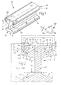
- a not covered by the invention composite profile 10 of the height h of here 105 mm and the maximum width b of 92 mm points to Fig. 1 a rail-like carrier profile 12 with a rail 14 and a molded thereto by means of a rail web 20 strand-like rail head 22.
- Two the foot surface 16 of the rail foot 14 limiting Longitudinal edges 17 of height c of 10 mm extend at a distance b x from here 80 mm parallel to each other.
- the two roof surfaces 18 of the rail foot 14 are slightly upwardly inclined to the longitudinal axis A of the composite profile 10 transverse cross-sectional central axis Q and go into those rail web 20 of height hi of about 30 mm and the thickness e of about 18 mm. From the upper end of the rail web 20 go to the longitudinal edges 24 of the rail head 22 approximately upwardly inclined lower surfaces 26 of this rail head 22 a width b 2 of 78 mm from whose outer height n of about 28 mm determines the position of the rail head surface 28.
- This rail or carrier profile 12 of the composite profile 10 is formed in a not shown for reasons of clarity in the drawing extruder from a light metal material.
- the head or surface 28 of the rail profile 12 and its rail head 22 is spanned in the final state of a profile strip 40 of thickness f of 6 mm, which is made of an iron or non-ferrous metal.
- This profile band 40 is shaped like a channel in cross section, and its outgoing from a base plate 42 - - parallel to each other and to the longitudinal axis B of the profile strip 40 - - side legs 46 of the height Ci of 20 mm are the longitudinal edges 24 of the rail head 22 at. In this position, the outer surface 44 of the profile strip 40 forms the surface of the composite profile 10th
- Each side leg 46 of the surface 28 of the rail head 22 resting profile strip 40 is in the embodiment of Fig. 1, 2 inside a channel-like insertion rod 50 approximately V-shaped cross section of an opening angle Wi of about 65 ° associated axially parallel, the
- Channel legs 49, 49i offer a thickness a x , which corresponds with a small clearance of the width a of the insertion slot 30.
- One of these cross-sectionally linear gutter legs 49 lies with its outer side - parallel to the cross-sectional longitudinal axis Q extending - the side legs 46 of the profile strip 40 on the inside in a contact width C 2 of 5 mm and is sealingly welded thereto by a weld indicated at 48. This runs on the end face 47 of the profile band side leg 46.
- the other channel leg 49i is inserted into the adjacent slot 30 of the rail head 22. The result is a permanent and dense composite of the two composite partners 12, 40 of the composite profile 10th
- a suitably shaped insert rod 50 a of the profile strip 40 up that in itself accordingly Fig. 2 is designed.
- For rail 14 towards the insertion slot 30 a is limited by an upwardly inclined longitudinal rib 34 a of the rail head 22 a .
- This slot 30 a takes the free end 55 of the Cross-section of the insertion rod 50 a , which is a side view of a longitudinal strip.
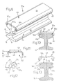
- profile strip 40 of Fig. 4 is i .w. according to the Fig. 2 designed; in this composite profile 10 b , however, the two insertion profiles or insertion rods 50 b are bent semicircular in cross-section and welded in each case in their zenith to the end face 47 of a side leg 46 of the profile strip 40.
- the insertion rods 50 b which open towards one another in the cross-sectional longitudinal axis Q, engage on the rail head 22 b a bead 36 of part-circular cross-sectional contour, which delimits longitudinal ribs 34 b on both sides, forming insertion slots 35 for the cross-sectional ends of the insertion rod 50b.
- Fig. 5 shows in each case one on the cross-sectional longitudinal axis Q ending half of two not encompassed by the invention composite profiles 10 c , 10 d ; the other half, not shown, is designed accordingly.
- the profile band 40 of in Fig. 5 left training is associated with a push rod 50 c of thickness ai, whose cross section consists of a quarter circle portion 54 and a linear portion 49 c , which is welded to the corresponding side legs 46 of the profile strip 40. That quadrant section 54 protrudes toward the rail foot 14.
- the insertion rod 50 c is set so that the quarter circle portion 54 is directed to the base plate 42 of the profile band 40.
- 10 d rests the linear portion in a longitudinal indentation 32 of the rail head 22 c and 22 d , which merges into a cross-sectional curved slot 30 c .
- FIG. 6 shows two oppositely directed insertion profiles or insertion rods 50 e / angle-shaped or hook-like - - and in a similar shape - - cross-sectional shape with corresponding slots in the rail head 22 e or 22 f of the composite profile 10 e , 10 f .
- These insertion rods 50 e are welded to the end face 47 of the profile band side leg 46 and engage behind with their free hook portion 56 an axially parallel pin bar 37 of the width k x of the rail head 22 e and 22 f .
- insert rod 50 g extends in the composite profile 10 g of Fig. 7 ; he is on the one hand welded to the inner surface of the side leg 46 and engages behind the other with its free hook end 56 a pin bar 37 in the longitudinal surface 24 of the rail head 22 g .
- the Fig. 7 is a cross-sectional linear insertion rod 51 of thickness 2 a of 4 mm inside and welded to the end face 47 of the side leg 46 so that even - - parallel to the latter - - free cross-sectional end of a pin bar 37 of the rail head 22h engages behind.
- the insertion rod 51 is directed towards the base plate 42, in the other composite profile 10 k , he shows of the base plate 42nd path.
- the corresponding slots 30 in the rail head 21i and 22 k each extending above a longitudinal rib 34 and 34 a.
- the composite profile 10e not covered by the invention Fig. 9 to 13 contains two insertion rods 50 a , whose shape has been described to Fig. 3. In contrast to that representation, here have the free ends 55 of the insertion rods 50 a upwards, ie towards the base plate 42 of the profile strip 40 out.
- FIG. 11 shows the exact design of the profile band 40 whose straight width q here measures 68 mm with an extended length of about 116 mm and an area of about 697 mm [Mat. 1.4016 (X 6 Cr 17), at 5373, 1 g / m].
- the insert rod 50 a of Fig. 12 determined with its two profile limbs 55, 55i of length z of 7, 8 mm and 5, 8 mm (Z 1 ) and the end faces 57 an angle y of 65 °.
- Fig. 13 shows the length of the slots 30 described above and longitudinal depressions 32 in the rail head 22 e .
- FIGS. 14 to 17 show that to the Fig. 10 to 13 discussed cycle for the embodiment of FIG. 3.
- Fig. 15 corresponds to the Fig. 11
- In Fig. 16 measures the length z or Zi both profile legs 55, 55i of the insertion rod 50 a 5, 6 mm and the angle y here 76 °.
- a height i of 28 forms whose Nutenianastes in cross section of a semicircle is determined.
- FIGS. 22 to 24 has an iw rectangular cross-sectional shape of the width bi of 105 mm and the height h 2 of 50 mm and is provided with an interior 62 which is bounded on either side by profile legs 64, of which - - parallel to the surface 28 and aligned with each other - Protect bottom webs 66 of width b 3 from 20 mm. That surface 28 is narrower than the carrier profile 13, since each of its upper corner edges has a step recess 68 of width b 4 of 5 mm. From the latter goes in Fig. 22 an essentially diagonal to the cross-sectional area directed slot 31 of width a of about 3 mm and the length t x of about 9 mm.
- the slot 31 serves to receive a cross-sectional angle-like insertion rod 50 a / is welded to a profile leg 55i to the longitudinal edge 70 of a plate-shaped profile strip 44, whose width b measures about 95 mm with a thickness f of 5 mm.
- the free profile leg 55 sits in the slot 31st
- the composite profiles 11 a and 11 b and the carrier profiles 13 of the Fig. 23 or 24 differ by the shape of the insertion profiles or insertion rods 51k or 50 of their profile strips 41.
- the insert rod 51 k of Fig. 23 is similar to that of the composite profile for 10 hours , but slightly bent.
- the insert rod 50 of the Fig. 24 corresponds to that of Fig. 1, 2 ,
- the carrier profile 13 is designed accordingly with a longitudinal indentation 32 in the head or surface 28 of the carrier profile 13 b and that Volunteerneinformung 68, between which a bead 3 ⁇ a parallel to the profile longitudinal axis.
Abstract
Description
Die Erfindung betrifft ein Verbundprofil mit einem aus Leichtmetallwerkstoff stranggepressten schienenartigen Tragkörper sowie einem dessen Kopffläche überspannenden Profilband aus einem härteren Metall nach dem Oberbegriff der unabhängigen Ansprüche 1 und 2, wie es aus der
Die nachveröffentlichte
Der 1897 veröffentlichten
Aus der
Der
Ein Verbundleiterschienenelement zur Stromversorgung eines Bahnfahrzeugs mit einem Belag aus einem Werkstoff hohen mechanischen Widerstandes, der starr auf einem Stab aus elektrisch gut leitfähigem Material befestigt ist sowie die Gleit- bzw. Kontaktfläche für Stromabnehmer des Fahrzeuges bildet, offenbart die
Als nachteilig haben sich auch Stromschienen erwiesen, deren Verschleißkomponente durch sie seitlich durchsetzende Schrauben oder zusätzliche Steckorgane am stromführenden Trägerprofil befestigt werden. Andere bekannte Herstellverfahren können nachteiligerweise zu Welligkeiten auf der Oberfläche des Deckprofiles führen, die ihre Ursache im schrittweisen Verstemmen bzw. Stanzen des Trägerprofiles haben.Busbars have proven to be disadvantageous, the wear component to be fastened by laterally passing through screws or additional plug-in organs on the current-carrying carrier profile. Other known manufacturing methods can disadvantageously lead to ripples on the surface of the cover profile, which have their cause in the stepwise caulking or punching of the carrier profile.
In Kenntnis dieses Standes der Technik hat sich der Erfinder das Ziel gesetzt, die Verbindung zwischen Trägerprofil und Profilband unter Beibehaltung der besonderen wirtschaftlichen Herstellungsmöglichkeiten zu verbessern.In view of this prior art, the inventor has set the goal to improve the connection between the carrier profile and the profile band while maintaining the special economic production possibilities.
Zur Lösung dieser Aufgabe führt die Lehre der unabhängigen Ansprüche 1 und 2; die Unteransprüche geben günstige Weiterbildungen an. Zudem fallen in den Rahmen der Erfindung alle Kombinationen aus zumindest zwei der in der Beschreibung, der Zeichnung und/oder den Ansprüchen offenbarten Merkmale. Bei angegebenen Benennungsbereichen sollen auch innerhalb der genannten Grenzen liegende Werte als Grenzwerte offenbart und beliebig einsetzbar sein.To achieve this object, the teaching of the independent claims 1 and 2; the dependent claims indicate favorable developments. In addition, all combinations of at least two of the features disclosed in the description, the drawings and / or the claims fall within the scope of the invention. For specified naming ranges should also Values within the stated limits are disclosed as limit values and can be used as desired.
Erfindungsgemäß ist an das der Kopf- oder Oberfläche des Trägerprofils etwa aufliegende Profilband oder Deckprofil - - bevorzugt aus Edelstahl - - an dessen Längsseiten jeweils ein zur Längsachse des Profilbandes paralleler Anker- oder Einschubstab angefügt, der anderseits in einen seitlichen Steckschlitz des Trägerprofils eingreift; der Einschubstab bzw. das Einschubprofil ist bevorzugt aus dem Werkstoff des Profilbandes gefertigt und mit letzterem durch eine Schweißnaht verbunden. Die Einschubstäbe ergänzen das Profilband auf beiden Seiten und bilden dank der geschweißten Anbindung einen sicheren Schutz für die innenliegende Oberfläche des stromführenden Trägerprofils.According to the invention, at the longitudinal side of each of the head or surface of the carrier profile about resting profile strip or cover profile - preferably stainless steel - - an armature or push rod parallel to the longitudinal axis of the profile band attached, on the other hand engages in a lateral insertion slot of the carrier profile; the insertion rod or the insertion profile is preferably made of the material of the profile strip and connected to the latter by a weld. The insert rods complete the profile band on both sides and, thanks to the welded connection, form a secure protection for the interior surface of the live carrier profile.
Nach einem weiteren Merkmal der Erfindung entspricht die Dicke des Einsteckendes des profilartigen Einschubstabes der Breite des Steckschlitzes im Trägerprofil, so dass ein fester Sitz der Komponenten aneinander zustande kommt.According to a further feature of the invention, the thickness of the insertion of the profile-like insertion rod corresponds to the width of the insertion slot in the carrier profile, so that a tight fit of the components comes together.
Als günstig hat es sich bei einem rinnenähnlich geformten Profilband erwiesen, das dem Schienenkopf eines schienenartigen Trägerprofils aufliegt, den Einschubstab mit einem - - an eine Grundplatte des Profilbandes angeformten - - Seitenschenkel zu verbinden sowie ihn anderseits mit wenigstens einem von jenem Seitenschenkel abragenden Stababschnitt in den entsprechend angeordneten Steckschlitz des Trägerprofils einzusetzen. Die Schweißnaht soll vorteilhafterweise an der Stirnfläche des Seitenschenkels jenes Profilbandes verlaufen.As low it has proven in a trough-shaped profiled strip that rests on the rail head of a rail-like carrier profile, the push rod with a - - molded to a base plate of the profile band - - side legs and on the other hand with at least one of that side leg projecting rod portion in the insert appropriately arranged slot of the carrier profile. The weld should advantageously extend on the end face of the side leg of that profile band.
Die Erfindung sieht hierbei im Querschnitt rechteckförmige Einschubstäbe vor, die innenseitig an den Seitenschenkeln des Profilbandes angelegt sind und deren jeweilige Stirnfläche überragen, mit der sie mittels einer durchgehenden Schweißnaht verbunden sind. Ein solcher im Querschnitt linearer Einschubstab ist erfindungsgemäß mit der Stirnfläche eines Profilband-Seitenschenkels verschweißt sowie zur Querschnittslängsachse des Verbundprofils in einem Winkel von etwa 60° bis 80° - - bevorzugt 70 ° bis 75° - - geneigt.The invention provides in this case in cross-section rectangular insertion rods, which are created on the inside of the side legs of the profile band and project beyond their respective end face, with which they by means of a continuous Weld seam are connected. Such a cross-sectional linear insertion rod according to the invention welded to the end face of a profile band side leg and the cross-sectional longitudinal axis of the composite profile at an angle of about 60 ° to 80 ° - - preferably 70 ° to 75 ° - - inclined.
Die Erfindung erfasst auch ein Verbundprofil zum Herstellen eines Verbundprofils, bei dem aus Leichtmetallwerkstoff ein Trägerprofil mit einer Kopffläche sowie diese beidseits begleitenden Steckschlitzen stranggepresst wird, zudem in jedem Steckschlitz ein Einschubstab eingebracht und an einen aus dem Steckschlitz ragenden Abschnitt des Einschubstabes ein die Kopffläche übergreifendes Profilband angelegt wird. Der Einschubstab wird mit dem Profilband durchgehend verschweißt.The invention also covers a composite profile for producing a composite profile in which a support profile with a top surface and this on both sides accompanying plug-in slots is extruded from light metal material, also introduced in each slot a plug insertion rod and to a protruding from the insertion slot portion of the insertion rod a head surface cross profile band is created. The insert rod is welded continuously to the profile strip.
Zuerst werden also die Einschubstäbe in das Leichtmetallprofil , insbesondere in ein AL-Basisprofil, eingelegt bzw. eingedrückt oder eingerollt oder auch vor dem Verschweißen bzw. im Nachhinein durch bleibende Verformung des Trägerprofils festgerollt oder festgedrückt. Vorgesehen ist dann mit Hilfe einer Andruckrolle mit großem Durchmesser das Edelstahl -Deckprofil auf das Leichtmetall-Trägerprofil zu drücken und unter dieser Vorspannung gleichzeitig rechts und links die Verankerungsstreifen oder Einschubstäbe mit dem Deckprofil zu verschweißen.First, therefore, the insertion rods in the light metal profile, in particular in an AL base profile, inserted or pressed or rolled or even rolled before welding or in retrospect by permanent deformation of the carrier profile or pressed. It is then planned using a pinch roller with a large diameter to push the stainless steel cover profile on the light metal carrier profile and at the same time under this bias to weld the anchoring strips or insertion rods with the cover profile right and left.
Im übrigen ist das sog. Deckprofil bevorzugt ein von einem Walzcoil geschnittenes Edelstahlband, das durch Rollformen in die gewünschte Form gebracht bzw. als geschnittenes Band direkt eingesetzt wird. Der Einschubstab ist ein Edelstahlband - - vorzugsweise die gleiche Legierung wie das Deckprofil - - das vorteilhafter Weise vom Walzcoil geschnitten und durch Rollformen/Abkanten/Aufbörteln/Umbörteln in die gewünschte Form gebracht worden ist.Otherwise, the so-called cover profile is preferably a stainless steel strip cut from a rolling coil, which is brought into the desired shape by roll forming or used directly as a cut strip. The insert rod is a stainless steel band - preferably the same alloy as the cover profile - which is advantageously cut from the rolling coil and has been brought into the desired shape by roll forming / folding / Auftörteln / Umbörteln.
Um die eingangs erwähnten Mängel zu beseitigen, wird ein kontinuierlich ablaufendes Verbundprofil - - wie Strangpressen für das Trägerprofil und Rollformen - - über die ganze Profillänge von Deckprofil und Einschubstäben bzw. Verankerungsprofilen vorgeschlagen. Die Verbindung wird durch kontinuierliches Schweißen über die Profillänge durchgeführt.To eliminate the deficiencies mentioned above, a continuously running composite profile - such as extrusions for the carrier profile and roll forming - - over the entire profile length of the cover profile and insertion bars or anchoring profiles is proposed. The connection is carried out by continuous welding over the profile length.
Gefordert wird eine größtmögliche Breite der Schleiffläche mit Bestreichmöglichkeit von der Seite und eine mechanische Verankerung, die auch bei komplett abgenutzten Verschleißprofilen eine Verankerung der dann zwei Restschleifflächen gewährleistet. Zudem ist eine Reduzierung der Einbau-Höhentoleranzen gegenüber bekannten Verbundprofilen erwünscht. Wünschenswert ist auch eine lokale Fertigungsmöglichkeit weltweit, ohne eine große Leichtmetall-Strangpresse aufrüsten zu müssen.Required is the widest possible width of the grinding surface with the possibility of brushing from the side and a mechanical anchoring that ensures anchoring of the then two residual grinding surfaces even with completely worn out wear profiles. In addition, a reduction of the installation height tolerances over known composite profiles is desired. Desirable is also a local manufacturing facility worldwide, without having to upgrade a large light metal extrusion press.
Weitere Vorteile, Merkmale und Einzelheiten der Erfindung ergeben sich aus der nachfolgenden Beschreibung bevorzugter Ausführungsbeispiele sowie anhand der Zeichnung; diese zeigt in
-
Fig. 1 ,9 : jeweils eine Schrägsicht auf einen Abschnitt eines schienenartigen Verbundprofils aus zwei Verbundpartnern; -
Fig. 2 : den Querschnitt durch das Verbundprofil derFig. 1 in etwa natürlicher Größe mit einem aus dem Verbundprofil herausgenommenen Bauteil; - Fig. 3,
4 : jeweils einen gegenüberFig. 2 verkleinerten Querschnitt durch ein Verbundprofil anderer Ausgestaltung; -
Fig. 5, 6, 7, 8 : jeweils zwei Hälften der Querschnitte zweier unterschiedlicher Verbundprofile; -
Fig. 10 : den Querschnitt durch das Verbundprofil derFig. 9 ; -
Fig. 11 : eine Stirnansicht des einen Verbundpartners; -
Fig. 12 : eine Seitenansicht zweier Elemente des Verbundpartners derFig. 11 ; -
Fig. 13 : die beiden Verbundpartner derFig. 10 vor dem Zusammenbau; -
Fig. 14 bzw. 18: zwei weitere Ausgestaltungen von Verbundprofilen aus zwei Verbundpartnern; -
Fig. 15 bzw. 19: eine Stirnansicht des einen Verbundpartners inFig. 14 bzw. 18; -
Fig. 16 bzw. 20: eine Seitenansicht zweier Elemente des Verbundpartners derFig. 15 bzw. 19 ; -
Fig. 19 , 20 : den Elementen derFig. 11, 12 entsprechende Darstellungen zuFig. 14 bzw. 18 ; -
Fig. 17 bzw. 21: jeweils die beiden Verbundpartner derFig. 14 bzw. 18 vor deren Zusammenbau; -
Fig. 22 bis 24 : drei andere Ausgestaltungen von Verbundprofilen in Stirnansicht .
-
Fig. 1 .9 in each case an oblique view of a section of a rail-like composite profile of two composite partners; -
Fig. 2 : the cross section through the composite profile ofFig. 1 in approximately natural size with a component taken out of the composite profile; - 3,
4 : one opposite eachFig. 2 reduced cross-section through a composite profile of another embodiment; -
Fig. 5, 6, 7, 8 : two halves of the cross sections of two different composite profiles; -
Fig. 10 : the cross section through the composite profile ofFig. 9 ; -
Fig. 11 : an end view of one federation partner; -
Fig. 12 : A side view of two members of the federation partnerFig. 11 ; -
Fig. 13 : the two partners of theFig. 10 before assembly; -
Fig. 14 and 18: two further embodiments of composite profiles from two composite partners; -
Fig. 15 or 19: an end view of the one partner inFig. 14 or 18; -
Fig. 16 and Fig. 20: a side view of two elements of the composite partner of theFig. 15 or 19; -
Fig. 19, 20 : the elements ofFig. 11, 12th corresponding representations tooFig. 14 or 18; -
Fig. 17 or 21: respectively the two partners of theFig. 14 or 18 before assembly; -
FIGS. 22 to 24 Three other embodiments of composite profiles in front view.
Ein nicht von der Erfindung umfasstes Verbundprofil 10 der Höhe h von hier 105 mm und der maximalen Breite b von 92 mm weist nach
Von diesen Längskanten 17 sind die beiden Dachflächen 18 des Schienenfußes 14 zu der die Längsachse A des Verbundprofils 10 querenden Querschnittsmittelachse Q geringfügig aufwärts geneigt und gehen in jenen Schienensteg 20 der Höhe hi von etwa 30 mm sowie der Dicke e von etwa 18 mm über. Vom oberen Ende des Schienensteges 20 gehen die zu den Längskanten 24 des Schienenkopfes 22 etwa aufwärts geneigten Unterflächen 26 dieses Schienenkopfes 22 einer Breite b2 von 78 mm ab, dessen Außenhöhe n von etwa 28 mm die Lage der Schienenkopf-Oberfläche 28 bestimmt.Of these
Von jeder der Längskanten 24 des Schienenkopfes 22 geht in
Dieses Schienen- oder Trägerprofil 12 des Verbundprofils 10 wird in einer aus Gründen der Übersichtlichkeit in der Zeichnung nicht wiedergegebenen Strangpresse aus einem Leichtmetallwerkstoff geformt.This rail or
Die Kopf- oder Oberfläche 28 des Schienenprofils 12 bzw. seines Schienenkopfes 22 wird in Endzustand von einem Profilband 40 der Dicke f von 6 mm überspannt, das aus einem Eisen- oder Buntmetall hergestellt ist. Dieses Profilband 40 ist im Querschnitt rinnenartig geformt, und seine von einer Grundplatte 42 ausgehenden - - zueinander sowie zur Längsachse B des Profilbandes 40 parallelen - - Seitenschenkel 46 der Höhe Ci von 20 mm liegen den Längskanten 24 des Schienenkopfes 22 an. In dieser Lage bildet die Außenfläche 44 des Profilbandes 40 die Oberfläche des Verbundprofils 10.The head or
Jedem Seitenschenkel 46 des der Oberfläche 28 des Schienenkopfs 22 aufliegenden Profilbandes 40 ist im Ausführungsbeispiel der
Rinnenschenkel 49, 49i eine Dicke ax anbieten, die mit geringem Spiel der Breite a des Steckschlitzes 30 entspricht. Der eine dieser im Querschnitt linearen Rinnenschenkel 49 liegt mit seiner Außenseite - - parallel zur Querschnittslängsachse Q verlaufend - - dem Seitenschenkel 46 des Profilbandes 40 innenseitig in einer Berührungsbreite C2 von 5 mm an und ist mit diesem durch eine bei 48 angedeutete Schweißnaht dichtend verschweißt. Diese verläuft an der Stirnfläche 47 des Profilband-Seitenschenkels 46. Der andere Rinnenschenkel 49i ist in den benachbarten Schlitz 30 des Schienenkopfes 22 eingefügt. So entsteht ein dauerhafter und dichter Verbund der beiden Verbundpartner 12, 40 des Verbundprofils 10.
Der Schienenkopf 22a des ebenfalls nicht von der Erfindung umfassten Verbundprofils 10a nach Fig. 3 weist statt eines V-artigen Schlitzes einen im Querschnitt winkelartig gebogenen Steckschlitz 30a der Breite (Radius 4 mm) für einen entsprechend geformten Einschubstab 50a des Profilbandes 40 auf, das an sich entsprechend
Auch das nicht von der Erfindung umfasste Profilband 40 der
Auch die nicht von der Erfindung umfasste
Ein im Querschnitt im Wesentlichen stufenartiger, nicht von der Erfindung umfasster Einschubstab 50g verläuft im Verbundprofil 10g der
An den Seitenschenkel 46 des Profilbandes 40 des von der Erfindung geschützten Verbundprofils 10h der
In den beiden ebenfalls durch die Erfindung geschützten Ausführungsbeispielen der
Das nicht von der Erfindung umfasste Verbundprofil 10e der
Der
Der Einschubstab 50a der
Die
An die Seitenschenkel 46 des nicht von der Erfindung umfassten Profilbandes 40 der
Zur klemmenden Aufnahme des Rundstabes 52 ist in die Höhenmitte der Längskanten oder -flächen 24 einer Höhe i von 28 formt, deren Nutentiefstes im Querschnitt von einem Halbkreis bestimmt ist.For clamping reception of the
Das nicht von der Erfindung umfasste kastenartige Trägerprofil 13 des Verbundprofils 11 der
Die Verbundprofile 11a und 11b bzw. deren Trägerprofile 13 der
Er ist jedoch mit einem Rinnenschenkel 49 an die Unterfläche 41 des Profilbandes 41 angelegt und so verschweißt; die Schweißnaht 48 verläuft an der Längskante 70 des Profilbandes 41 und der Außenfläche des Rinnenschenkels 49. Der Eckbereich des Trägerprofils 13 ist entsprechend gestaltet mit einer Längseinformung 32 in der Kopf- oder Oberfläche 28 des Trägerprofils 13b und jener Stufeneinformung 68, zwischen denen ein Wulst 3βa parallel zur Profillängsachse verläuft.However, it is applied with a
Claims (11)
dadurch gekennzeichnet,
dass der Einschubstab (51) in einen seitlichen Schlitz (30) des Trägerprofils (12) eingreift, dass der Einschubstab (51) einen rechteckförmigen Querschnitt aufweist, der mit der Stirnfläche (47) eines Profil-Seitenschenkels (46) verschweißt ist sowie zu einer Querschnittslängsachse (Q) des Verbundprofils (10i) in einem Winkel (w2) von etwa 60° bis 80°, bevorzugt 70° bis 75°, geneigt ist.Composite profile (10i) with an extruded from light metal material carrier profile (12) and a top surface (28) spanning profile band (40) made of a harder metal, at its longitudinal sides in each case one to its longitudinal axis (B) parallel insertion rod (51) is added, said the insertion rod (51) is connected to its profile band (40) by a weld seam (48),
characterized,
in that the insertion rod (51) engages in a lateral slot (30) of the carrier profile (12), in that the insertion rod (51) has a rectangular cross-section which is welded to the end face (47) of a profile side limb (46) and to one Cross-sectional longitudinal axis (Q) of the composite profile (10i) at an angle (w 2 ) of about 60 ° to 80 °, preferably 70 ° to 75 °, is inclined.
dadurch gekennzeichnet,
dass der Einschubstab (51) in einen seitlichen Schlitz des Trägerprofils (12) eingreift, dass der Einschubstab (51) einen rechteckförmigen Querschnitt aufweist, der innenseitig an den Profil-Seitenschenkel (46) angelegt ist und dessen Stirnfläche (47) überragt, mit der er verschweißt ist.Composite profile (10h) with an extruded from light metal material carrier profile (12) and a top surface (28) spanning profile band (40) made of a harder metal, on its longitudinal sides in each case one to its longitudinal axis (B) parallel insertion rod (51) is added, said the insertion rod (51) is connected to its profile band (40) by a weld seam (48),
characterized,
in that the push rod (51) engages in a lateral slot of the carrier profile (12), in that the push rod (51) has a rectangular cross-section which is arranged on the inside of the profile side limb (46) and projects beyond the end face (47) thereof he is welded.
Applications Claiming Priority (2)
| Application Number | Priority Date | Filing Date | Title |
|---|---|---|---|
| DE102005004547A DE102005004547B4 (en) | 2005-01-31 | 2005-01-31 | Composite profile with a support body made of light metal material and a profiled strip and method for producing the composite profile |
| EP05824450.0A EP1843866B2 (en) | 2005-01-31 | 2005-12-20 | Composite profile provided with a support body made of a light metal material and a profiled strip and a method for producing said profile |
Related Parent Applications (3)
| Application Number | Title | Priority Date | Filing Date |
|---|---|---|---|
| EP05824450.0 Division | 2005-12-20 | ||
| EP05824450.0A Division EP1843866B2 (en) | 2005-01-31 | 2005-12-20 | Composite profile provided with a support body made of a light metal material and a profiled strip and a method for producing said profile |
| EP05824450.0A Division-Into EP1843866B2 (en) | 2005-01-31 | 2005-12-20 | Composite profile provided with a support body made of a light metal material and a profiled strip and a method for producing said profile |
Publications (3)
| Publication Number | Publication Date |
|---|---|
| EP2108470A2 true EP2108470A2 (en) | 2009-10-14 |
| EP2108470A3 EP2108470A3 (en) | 2010-08-25 |
| EP2108470B1 EP2108470B1 (en) | 2011-07-06 |
Family
ID=36033233
Family Applications (2)
| Application Number | Title | Priority Date | Filing Date |
|---|---|---|---|
| EP09008239A Active EP2108470B1 (en) | 2005-01-31 | 2005-12-20 | Compound profile with a support body of light metallic material and a profile band and method for producing the compound profile |
| EP05824450.0A Active EP1843866B2 (en) | 2005-01-31 | 2005-12-20 | Composite profile provided with a support body made of a light metal material and a profiled strip and a method for producing said profile |
Family Applications After (1)
| Application Number | Title | Priority Date | Filing Date |
|---|---|---|---|
| EP05824450.0A Active EP1843866B2 (en) | 2005-01-31 | 2005-12-20 | Composite profile provided with a support body made of a light metal material and a profiled strip and a method for producing said profile |
Country Status (19)
| Country | Link |
|---|---|
| US (1) | US7954611B2 (en) |
| EP (2) | EP2108470B1 (en) |
| JP (1) | JP2008538092A (en) |
| KR (1) | KR101115970B1 (en) |
| CN (1) | CN101111330B (en) |
| AT (2) | ATE515340T1 (en) |
| BR (1) | BRPI0519881A2 (en) |
| CA (1) | CA2596347C (en) |
| DE (5) | DE102005004547B4 (en) |
| DK (1) | DK1843866T4 (en) |
| ES (1) | ES2360230T5 (en) |
| NO (1) | NO20073972L (en) |
| PL (1) | PL1843866T3 (en) |
| PT (1) | PT1843866E (en) |
| RU (1) | RU2384426C2 (en) |
| TW (1) | TWI307644B (en) |
| UA (1) | UA89520C2 (en) |
| WO (1) | WO2006081863A1 (en) |
| ZA (1) | ZA200706188B (en) |
Families Citing this family (20)
| Publication number | Priority date | Publication date | Assignee | Title |
|---|---|---|---|---|
| DE102005004547B4 (en) | 2005-01-31 | 2007-11-08 | Alcan Technology & Management Ag | Composite profile with a support body made of light metal material and a profiled strip and method for producing the composite profile |
| GB2433908B (en) * | 2006-06-03 | 2008-05-07 | Brecknell Willis & Co Ltd | Conductor rails |
| US7712591B2 (en) | 2006-11-24 | 2010-05-11 | Alcan Technology And Management Ltd. | Composite profile and method for manufacturing the composite profile |
| DE102007003553B4 (en) | 2006-11-24 | 2010-06-17 | Alcan Technology & Management Ag | Composite profile with a support body made of light metal material and a profiled strip and method for producing the composite profile |
| US20110278120A1 (en) * | 2010-05-17 | 2011-11-17 | Alcoa Inc. | Wear resistant transportation systems, methods, and apparatus |
| US8636124B2 (en) | 2010-09-23 | 2014-01-28 | Caterpillar Inc. | Coated power rail |
| DE102011050920A1 (en) | 2011-06-08 | 2012-12-13 | Hammerer Aluminium Industries Extrusion Gmbh | Busbar, corresponding assembly and disassembly method and arrangement of such busbars |
| CN102581207A (en) * | 2012-03-13 | 2012-07-18 | 宜兴市宝登合金有限公司 | Manufacturing method of steel-aluminum composite section bar used for contact rail in urban railway system |
| KR101367944B1 (en) * | 2013-01-07 | 2014-02-27 | 백경호 | Sheet feeding device |
| CN103212601B (en) * | 2013-04-08 | 2016-02-03 | 无锡市百宏传动电器有限公司 | A kind of single cylinder extrusion equipment of trolley composite conducting track and production method |
| CN103182400B (en) * | 2013-04-08 | 2015-05-27 | 无锡市百宏传动电器有限公司 | Double-cylinder extrusion equipment and production method of trolley conductor composite conductive tracks |
| CN103591438A (en) * | 2013-10-18 | 2014-02-19 | 天长市飞龙金属制品有限公司 | Steel grating and flat steel for steel grating |
| RS63313B1 (en) * | 2015-03-25 | 2022-07-29 | Alstom Transp Tech | Conductor rail for transmitting electric energy to a train |
| RU2616319C1 (en) * | 2016-03-16 | 2017-04-14 | Игорь Венедиктович Данилов | Conductor rail |
| CN106812030B (en) * | 2016-12-14 | 2018-07-13 | 安徽鑫铂铝业股份有限公司 | A kind of skewed slot high intensity high ferro guide rail aluminium section bar |
| CN110316024B (en) * | 2018-03-29 | 2022-09-09 | 比亚迪股份有限公司 | Composite conductor rail and manufacturing method thereof |
| USD894045S1 (en) * | 2018-06-01 | 2020-08-25 | Conductix, Inc. | Rail |
| RU2714470C1 (en) * | 2019-05-27 | 2020-02-17 | Игорь Венедиктович Данилов | Bimetallic current-conducting rail and method of its manufacturing |
| CN112297960B (en) * | 2019-07-26 | 2022-03-18 | 比亚迪股份有限公司 | Joint device for conductor rail and conductor rail system with same |
| CN112440833A (en) * | 2019-08-29 | 2021-03-05 | 比亚迪股份有限公司 | Conductive track and rail vehicle running track |
Citations (6)
| Publication number | Priority date | Publication date | Assignee | Title |
|---|---|---|---|---|
| US588541A (en) | 1897-08-17 | Current-conducting rail for electric railways | ||
| DE2432541A1 (en) | 1974-07-04 | 1976-01-22 | Aluminium Walzwerke Singen | METHOD AND DEVICE FOR PRODUCING COMPOSITE PROFILES OR DGL. |
| DE2546026A1 (en) | 1975-10-14 | 1977-04-21 | Gennevilliers Acieries | Hard cover for conductor rail - has cover clipped over soft high conductivity core and crimped at edges |
| US5047595A (en) | 1989-05-20 | 1991-09-10 | Willis Brecknell & Co., Limited | Conductor rails |
| DE4410688A1 (en) | 1994-03-28 | 1995-10-05 | Alusuisse Lonza Services Ag | Compound profile |
| EP1683676A1 (en) | 2005-01-19 | 2006-07-26 | Conductix, Inc. | Composite current rail |
Family Cites Families (8)
| Publication number | Priority date | Publication date | Assignee | Title |
|---|---|---|---|---|
| CH541453A (en) * | 1972-03-17 | 1973-09-15 | Alusuisse | Busbar |
| FR2286680A1 (en) * | 1974-10-02 | 1976-04-30 | Gennevilliers Acieries | Composite conductor rail for transport system - has stainless steel cover strip secured to aluminium section by deformation |
| JPH0295939A (en) * | 1988-09-30 | 1990-04-06 | Hitachi Cable Ltd | Complex rigid type electric-car line |
| GB2259894B (en) * | 1991-09-28 | 1995-05-17 | Brecknell Willis & Co Ltd | Conductor rails |
| DE19840720A1 (en) * | 1998-09-07 | 2000-03-16 | Joachim Glueck | Composite profile |
| US7116374B2 (en) * | 2003-08-26 | 2006-10-03 | Koplar Interactive Systems International, L.L.C. | Method and system for enhanced modulation of video signals |
| DE102005004547B4 (en) | 2005-01-31 | 2007-11-08 | Alcan Technology & Management Ag | Composite profile with a support body made of light metal material and a profiled strip and method for producing the composite profile |
| US7712591B2 (en) * | 2006-11-24 | 2010-05-11 | Alcan Technology And Management Ltd. | Composite profile and method for manufacturing the composite profile |
-
2005
- 2005-01-31 DE DE102005004547A patent/DE102005004547B4/en active Active
- 2005-01-31 DE DE200520006592 patent/DE202005006592U1/en not_active Expired - Lifetime
- 2005-01-31 DE DE102005063436A patent/DE102005063436B9/en active Active
- 2005-12-20 PL PL05824450T patent/PL1843866T3/en unknown
- 2005-12-20 RU RU2007132706/02A patent/RU2384426C2/en not_active IP Right Cessation
- 2005-12-20 UA UAA200709740A patent/UA89520C2/en unknown
- 2005-12-20 WO PCT/EP2005/013718 patent/WO2006081863A1/en active Application Filing
- 2005-12-20 JP JP2007552523A patent/JP2008538092A/en active Pending
- 2005-12-20 AT AT09008239T patent/ATE515340T1/en active
- 2005-12-20 PT PT05824450T patent/PT1843866E/en unknown
- 2005-12-20 AT AT05824450T patent/ATE496712T1/en active
- 2005-12-20 KR KR1020077017715A patent/KR101115970B1/en active IP Right Grant
- 2005-12-20 CA CA002596347A patent/CA2596347C/en active Active
- 2005-12-20 DE DE502005010926T patent/DE502005010926D1/en active Active
- 2005-12-20 EP EP09008239A patent/EP2108470B1/en active Active
- 2005-12-20 DK DK05824450.0T patent/DK1843866T4/en active
- 2005-12-20 US US11/815,018 patent/US7954611B2/en active Active
- 2005-12-20 ES ES05824450.0T patent/ES2360230T5/en active Active
- 2005-12-20 CN CN2005800474651A patent/CN101111330B/en active Active
- 2005-12-20 EP EP05824450.0A patent/EP1843866B2/en active Active
- 2005-12-20 BR BRPI0519881-0A patent/BRPI0519881A2/en not_active IP Right Cessation
- 2005-12-30 TW TW094147858A patent/TWI307644B/en active
-
2006
- 2006-03-02 DE DE102006009604A patent/DE102006009604B4/en active Active
-
2007
- 2007-07-26 ZA ZA200706188A patent/ZA200706188B/en unknown
- 2007-07-30 NO NO20073972A patent/NO20073972L/en not_active Application Discontinuation
Patent Citations (6)
| Publication number | Priority date | Publication date | Assignee | Title |
|---|---|---|---|---|
| US588541A (en) | 1897-08-17 | Current-conducting rail for electric railways | ||
| DE2432541A1 (en) | 1974-07-04 | 1976-01-22 | Aluminium Walzwerke Singen | METHOD AND DEVICE FOR PRODUCING COMPOSITE PROFILES OR DGL. |
| DE2546026A1 (en) | 1975-10-14 | 1977-04-21 | Gennevilliers Acieries | Hard cover for conductor rail - has cover clipped over soft high conductivity core and crimped at edges |
| US5047595A (en) | 1989-05-20 | 1991-09-10 | Willis Brecknell & Co., Limited | Conductor rails |
| DE4410688A1 (en) | 1994-03-28 | 1995-10-05 | Alusuisse Lonza Services Ag | Compound profile |
| EP1683676A1 (en) | 2005-01-19 | 2006-07-26 | Conductix, Inc. | Composite current rail |
Also Published As
Similar Documents
| Publication | Publication Date | Title |
|---|---|---|
| EP2108470B1 (en) | Compound profile with a support body of light metallic material and a profile band and method for producing the compound profile | |
| EP2029946B1 (en) | Mounting system, in particular for solar modules | |
| EP1993871A1 (en) | Composite profiled element comprising a carrier body consisting of a light metal material and a profiled strip, and method for producing said composite profiled element | |
| EP2656462B1 (en) | Contact line and carrier rail for a carriage which is supplied with power via a contact line | |
| EP1113944B1 (en) | Composite profiled section | |
| DE102007003553B4 (en) | Composite profile with a support body made of light metal material and a profiled strip and method for producing the composite profile | |
| EP0380445A1 (en) | Composite current rail of aluminium and steel, especially for a high-power railway current rail | |
| DE19609006C2 (en) | System of at least two composite profiles as busbars | |
| DE2538393A1 (en) | TRACK WITH A CONTINUOUS TRANSITION FOR THE COLLECTOR | |
| DE202008015077U1 (en) | Adapter for fixing solar modules, solar modules mounted with adapter and tool for releasing the fastening | |
| DE10216250B4 (en) | End piece for a busbar of a busbar system | |
| DE202007007976U1 (en) | Mounting system, in particular solar modules | |
| WO2012168461A2 (en) | Power rail, mounting and dismounting method and arrangement composed of combined power rails | |
| EP0793324A2 (en) | System comprising at least two electrically connected bus bars | |
| DE102008057276A1 (en) | Adapters for fixing solar modules, solar modules mounted with adapters and methods of fixing solar modules | |
| AT503285B1 (en) | Thermally insulated lorry upper part e.g. trunk, has intermediate profile connected to recess of outer profile, cover serving as air gap and provided at side wall, and insulation agent filling gap between panels | |
| EP1000675B1 (en) | Conductor rail, its use and method for its manufacture | |
| DE3249938C2 (en) | ||
| EP1256685A2 (en) | Door with at least one leaf | |
| AT409998B (en) | GOAL | |
| DE1440675C (en) | Composite busbar, especially for electric vehicles and cranes | |
| DE19857114A1 (en) | Conductor rail with I-shaped profile for railway has extruded aluminum alloy section fitted into I-shaped section and covered with profile components | |
| DE2164792B2 (en) | Method of mfg. box-section girders - has side plates fitting in grooves in upper and lower plates | |
| DE10332214A1 (en) | Molded/shaped rail e.g. for electric components rail, such as outlet box- or lighting-rail, has grounding conductor press-fitted onto molded rail | |
| WO1999002364A1 (en) | Elongated fish-plate for joining two elongated conductor rails and pair of conductor rails joined by such a fish-plate |
Legal Events
| Date | Code | Title | Description |
|---|---|---|---|
| PUAI | Public reference made under article 153(3) epc to a published international application that has entered the european phase |
Free format text: ORIGINAL CODE: 0009012 |
|
| AC | Divisional application: reference to earlier application |
Ref document number: 1843866 Country of ref document: EP Kind code of ref document: P |
|
| AK | Designated contracting states |
Kind code of ref document: A2 Designated state(s): AT BE BG CH CY CZ DE DK EE ES FI FR GB GR HU IE IS IT LI LT LU LV MC NL PL PT RO SE SI SK TR |
|
| RIN1 | Information on inventor provided before grant (corrected) |
Inventor name: WOEMPNER, DIETHELM Inventor name: NETZEL, TIMO |
|
| RAP1 | Party data changed (applicant data changed or rights of an application transferred) |
Owner name: 3A TECHNOLOGY & MANAGEMENT AG |
|
| PUAL | Search report despatched |
Free format text: ORIGINAL CODE: 0009013 |
|
| AK | Designated contracting states |
Kind code of ref document: A3 Designated state(s): AT BE BG CH CY CZ DE DK EE ES FI FR GB GR HU IE IS IT LI LT LU LV MC NL PL PT RO SE SI SK TR |
|
| AX | Request for extension of the european patent |
Extension state: HR |
|
| 17P | Request for examination filed |
Effective date: 20101216 |
|
| GRAP | Despatch of communication of intention to grant a patent |
Free format text: ORIGINAL CODE: EPIDOSNIGR1 |
|
| RIC1 | Information provided on ipc code assigned before grant |
Ipc: B60M 1/30 20060101ALI20110224BHEP Ipc: B21K 9/00 20060101AFI20110224BHEP |
|
| RAP1 | Party data changed (applicant data changed or rights of an application transferred) |
Owner name: ENGINEERED PRODUCTS SWITZERLAND AG (LTD.) |
|
| GRAS | Grant fee paid |
Free format text: ORIGINAL CODE: EPIDOSNIGR3 |
|
| GRAA | (expected) grant |
Free format text: ORIGINAL CODE: 0009210 |
|
| AC | Divisional application: reference to earlier application |
Ref document number: 1843866 Country of ref document: EP Kind code of ref document: P |
|
| AK | Designated contracting states |
Kind code of ref document: B1 Designated state(s): AT BE BG CH CY CZ DE DK EE ES FI FR GB GR HU IE IS IT LI LT LU LV MC NL PL PT RO SE SI SK TR |
|
| REG | Reference to a national code |
Ref country code: GB Ref legal event code: FG4D Free format text: NOT ENGLISH |
|
| REG | Reference to a national code |
Ref country code: CH Ref legal event code: EP |
|
| REG | Reference to a national code |
Ref country code: IE Ref legal event code: FG4D Free format text: LANGUAGE OF EP DOCUMENT: GERMAN |
|
| REG | Reference to a national code |
Ref country code: DE Ref legal event code: R096 Ref document number: 502005011603 Country of ref document: DE Effective date: 20110901 |
|
| REG | Reference to a national code |
Ref country code: NL Ref legal event code: T3 |
|
| REG | Reference to a national code |
Ref country code: NL Ref legal event code: TD Effective date: 20111103 |
|
| PG25 | Lapsed in a contracting state [announced via postgrant information from national office to epo] |
Ref country code: SI Free format text: LAPSE BECAUSE OF FAILURE TO SUBMIT A TRANSLATION OF THE DESCRIPTION OR TO PAY THE FEE WITHIN THE PRESCRIBED TIME-LIMIT Effective date: 20110706 |
|
| REG | Reference to a national code |
Ref country code: FR Ref legal event code: CD Owner name: CONSTELLIUM SWITZERLAND AG, CH Effective date: 20111130 |
|
| RAP2 | Party data changed (patent owner data changed or rights of a patent transferred) |
Owner name: CONSTELLIUM SWITZERLAND AG |
|
| PG25 | Lapsed in a contracting state [announced via postgrant information from national office to epo] |
Ref country code: IS Free format text: LAPSE BECAUSE OF FAILURE TO SUBMIT A TRANSLATION OF THE DESCRIPTION OR TO PAY THE FEE WITHIN THE PRESCRIBED TIME-LIMIT Effective date: 20111106 Ref country code: FI Free format text: LAPSE BECAUSE OF FAILURE TO SUBMIT A TRANSLATION OF THE DESCRIPTION OR TO PAY THE FEE WITHIN THE PRESCRIBED TIME-LIMIT Effective date: 20110706 Ref country code: LT Free format text: LAPSE BECAUSE OF FAILURE TO SUBMIT A TRANSLATION OF THE DESCRIPTION OR TO PAY THE FEE WITHIN THE PRESCRIBED TIME-LIMIT Effective date: 20110706 Ref country code: SE Free format text: LAPSE BECAUSE OF FAILURE TO SUBMIT A TRANSLATION OF THE DESCRIPTION OR TO PAY THE FEE WITHIN THE PRESCRIBED TIME-LIMIT Effective date: 20110706 Ref country code: PT Free format text: LAPSE BECAUSE OF FAILURE TO SUBMIT A TRANSLATION OF THE DESCRIPTION OR TO PAY THE FEE WITHIN THE PRESCRIBED TIME-LIMIT Effective date: 20111107 |
|
| REG | Reference to a national code |
Ref country code: IE Ref legal event code: FD4D |
|
| PG25 | Lapsed in a contracting state [announced via postgrant information from national office to epo] |
Ref country code: PL Free format text: LAPSE BECAUSE OF FAILURE TO SUBMIT A TRANSLATION OF THE DESCRIPTION OR TO PAY THE FEE WITHIN THE PRESCRIBED TIME-LIMIT Effective date: 20110706 Ref country code: GR Free format text: LAPSE BECAUSE OF FAILURE TO SUBMIT A TRANSLATION OF THE DESCRIPTION OR TO PAY THE FEE WITHIN THE PRESCRIBED TIME-LIMIT Effective date: 20111007 Ref country code: LV Free format text: LAPSE BECAUSE OF FAILURE TO SUBMIT A TRANSLATION OF THE DESCRIPTION OR TO PAY THE FEE WITHIN THE PRESCRIBED TIME-LIMIT Effective date: 20110706 Ref country code: CY Free format text: LAPSE BECAUSE OF FAILURE TO SUBMIT A TRANSLATION OF THE DESCRIPTION OR TO PAY THE FEE WITHIN THE PRESCRIBED TIME-LIMIT Effective date: 20110706 |
|
| PG25 | Lapsed in a contracting state [announced via postgrant information from national office to epo] |
Ref country code: SK Free format text: LAPSE BECAUSE OF FAILURE TO SUBMIT A TRANSLATION OF THE DESCRIPTION OR TO PAY THE FEE WITHIN THE PRESCRIBED TIME-LIMIT Effective date: 20110706 Ref country code: IE Free format text: LAPSE BECAUSE OF FAILURE TO SUBMIT A TRANSLATION OF THE DESCRIPTION OR TO PAY THE FEE WITHIN THE PRESCRIBED TIME-LIMIT Effective date: 20110706 |
|
| PLBE | No opposition filed within time limit |
Free format text: ORIGINAL CODE: 0009261 |
|
| STAA | Information on the status of an ep patent application or granted ep patent |
Free format text: STATUS: NO OPPOSITION FILED WITHIN TIME LIMIT |
|
| PG25 | Lapsed in a contracting state [announced via postgrant information from national office to epo] |
Ref country code: EE Free format text: LAPSE BECAUSE OF FAILURE TO SUBMIT A TRANSLATION OF THE DESCRIPTION OR TO PAY THE FEE WITHIN THE PRESCRIBED TIME-LIMIT Effective date: 20110706 Ref country code: RO Free format text: LAPSE BECAUSE OF FAILURE TO SUBMIT A TRANSLATION OF THE DESCRIPTION OR TO PAY THE FEE WITHIN THE PRESCRIBED TIME-LIMIT Effective date: 20110706 Ref country code: IT Free format text: LAPSE BECAUSE OF FAILURE TO SUBMIT A TRANSLATION OF THE DESCRIPTION OR TO PAY THE FEE WITHIN THE PRESCRIBED TIME-LIMIT Effective date: 20110706 |
|
| 26N | No opposition filed |
Effective date: 20120411 |
|
| PG25 | Lapsed in a contracting state [announced via postgrant information from national office to epo] |
Ref country code: DK Free format text: LAPSE BECAUSE OF FAILURE TO SUBMIT A TRANSLATION OF THE DESCRIPTION OR TO PAY THE FEE WITHIN THE PRESCRIBED TIME-LIMIT Effective date: 20110706 |
|
| BERE | Be: lapsed |
Owner name: ENGINEERED PRODUCTS SWITZERLAND A.G. (LTD.) Effective date: 20111231 |
|
| REG | Reference to a national code |
Ref country code: DE Ref legal event code: R081 Ref document number: 502005011603 Country of ref document: DE Owner name: CONSTELLIUM SWITZERLAND AG, CH Free format text: FORMER OWNER: ENGINEERED PRODUCTS SWITZERLAND AG (LTD.), ZUERICH, CH Effective date: 20120515 |
|
| PG25 | Lapsed in a contracting state [announced via postgrant information from national office to epo] |
Ref country code: MC Free format text: LAPSE BECAUSE OF NON-PAYMENT OF DUE FEES Effective date: 20111231 |
|
| REG | Reference to a national code |
Ref country code: CH Ref legal event code: PL |
|
| REG | Reference to a national code |
Ref country code: DE Ref legal event code: R097 Ref document number: 502005011603 Country of ref document: DE Effective date: 20120411 |
|
| PG25 | Lapsed in a contracting state [announced via postgrant information from national office to epo] |
Ref country code: LI Free format text: LAPSE BECAUSE OF NON-PAYMENT OF DUE FEES Effective date: 20111231 Ref country code: CH Free format text: LAPSE BECAUSE OF NON-PAYMENT OF DUE FEES Effective date: 20111231 Ref country code: BE Free format text: LAPSE BECAUSE OF NON-PAYMENT OF DUE FEES Effective date: 20111231 |
|
| PG25 | Lapsed in a contracting state [announced via postgrant information from national office to epo] |
Ref country code: ES Free format text: LAPSE BECAUSE OF FAILURE TO SUBMIT A TRANSLATION OF THE DESCRIPTION OR TO PAY THE FEE WITHIN THE PRESCRIBED TIME-LIMIT Effective date: 20111017 |
|
| PG25 | Lapsed in a contracting state [announced via postgrant information from national office to epo] |
Ref country code: LU Free format text: LAPSE BECAUSE OF NON-PAYMENT OF DUE FEES Effective date: 20111220 |
|
| PG25 | Lapsed in a contracting state [announced via postgrant information from national office to epo] |
Ref country code: BG Free format text: LAPSE BECAUSE OF FAILURE TO SUBMIT A TRANSLATION OF THE DESCRIPTION OR TO PAY THE FEE WITHIN THE PRESCRIBED TIME-LIMIT Effective date: 20111006 |
|
| PG25 | Lapsed in a contracting state [announced via postgrant information from national office to epo] |
Ref country code: TR Free format text: LAPSE BECAUSE OF FAILURE TO SUBMIT A TRANSLATION OF THE DESCRIPTION OR TO PAY THE FEE WITHIN THE PRESCRIBED TIME-LIMIT Effective date: 20110706 |
|
| PG25 | Lapsed in a contracting state [announced via postgrant information from national office to epo] |
Ref country code: HU Free format text: LAPSE BECAUSE OF FAILURE TO SUBMIT A TRANSLATION OF THE DESCRIPTION OR TO PAY THE FEE WITHIN THE PRESCRIBED TIME-LIMIT Effective date: 20110706 |
|
| REG | Reference to a national code |
Ref country code: AT Ref legal event code: HC Ref document number: 515340 Country of ref document: AT Kind code of ref document: T Owner name: CONSTELLIUM SWITZERLAND AG, CH Effective date: 20131008 |
|
| REG | Reference to a national code |
Ref country code: FR Ref legal event code: PLFP Year of fee payment: 11 |
|
| REG | Reference to a national code |
Ref country code: FR Ref legal event code: PLFP Year of fee payment: 12 |
|
| REG | Reference to a national code |
Ref country code: FR Ref legal event code: PLFP Year of fee payment: 13 |
|
| PGFP | Annual fee paid to national office [announced via postgrant information from national office to epo] |
Ref country code: DE Payment date: 20221228 Year of fee payment: 18 |
|
| P01 | Opt-out of the competence of the unified patent court (upc) registered |
Effective date: 20230411 |
|
| PGFP | Annual fee paid to national office [announced via postgrant information from national office to epo] |
Ref country code: GB Payment date: 20231227 Year of fee payment: 19 |
|
| PGFP | Annual fee paid to national office [announced via postgrant information from national office to epo] |
Ref country code: NL Payment date: 20231226 Year of fee payment: 19 Ref country code: FR Payment date: 20231227 Year of fee payment: 19 Ref country code: CZ Payment date: 20231206 Year of fee payment: 19 Ref country code: AT Payment date: 20231204 Year of fee payment: 19 |