EP2107364A1 - Capteur de gaz - Google Patents
Capteur de gaz Download PDFInfo
- Publication number
- EP2107364A1 EP2107364A1 EP09004846A EP09004846A EP2107364A1 EP 2107364 A1 EP2107364 A1 EP 2107364A1 EP 09004846 A EP09004846 A EP 09004846A EP 09004846 A EP09004846 A EP 09004846A EP 2107364 A1 EP2107364 A1 EP 2107364A1
- Authority
- EP
- European Patent Office
- Prior art keywords
- resistance portion
- longitudinal direction
- resistance
- gas sensor
- heater
- Prior art date
- Legal status (The legal status is an assumption and is not a legal conclusion. Google has not performed a legal analysis and makes no representation as to the accuracy of the status listed.)
- Granted
Links
- 238000005086 pumping Methods 0.000 claims abstract description 87
- 238000005259 measurement Methods 0.000 claims abstract description 50
- 238000010438 heat treatment Methods 0.000 claims abstract description 15
- 239000007789 gas Substances 0.000 claims description 102
- 239000001301 oxygen Substances 0.000 claims description 40
- 229910052760 oxygen Inorganic materials 0.000 claims description 40
- QVGXLLKOCUKJST-UHFFFAOYSA-N atomic oxygen Chemical compound [O] QVGXLLKOCUKJST-UHFFFAOYSA-N 0.000 claims description 37
- 239000007787 solid Substances 0.000 claims description 27
- 239000000463 material Substances 0.000 claims description 7
- 230000036961 partial effect Effects 0.000 claims description 6
- 238000004891 communication Methods 0.000 claims description 5
- 239000000470 constituent Substances 0.000 claims description 5
- 230000008878 coupling Effects 0.000 claims description 4
- 238000010168 coupling process Methods 0.000 claims description 4
- 238000005859 coupling reaction Methods 0.000 claims description 4
- MWUXSHHQAYIFBG-UHFFFAOYSA-N nitrogen oxide Inorganic materials O=[N] MWUXSHHQAYIFBG-UHFFFAOYSA-N 0.000 description 149
- 239000010410 layer Substances 0.000 description 40
- 229910052751 metal Inorganic materials 0.000 description 16
- 239000002184 metal Substances 0.000 description 16
- 239000000919 ceramic Substances 0.000 description 15
- 230000008859 change Effects 0.000 description 11
- BASFCYQUMIYNBI-UHFFFAOYSA-N platinum Chemical compound [Pt] BASFCYQUMIYNBI-UHFFFAOYSA-N 0.000 description 11
- MCMNRKCIXSYSNV-UHFFFAOYSA-N Zirconium dioxide Chemical compound O=[Zr]=O MCMNRKCIXSYSNV-UHFFFAOYSA-N 0.000 description 10
- 238000001514 detection method Methods 0.000 description 9
- 238000009413 insulation Methods 0.000 description 8
- 238000000034 method Methods 0.000 description 6
- 230000007423 decrease Effects 0.000 description 5
- 238000013021 overheating Methods 0.000 description 5
- 230000003247 decreasing effect Effects 0.000 description 4
- 230000007812 deficiency Effects 0.000 description 4
- 230000001747 exhibiting effect Effects 0.000 description 4
- 229910052697 platinum Inorganic materials 0.000 description 4
- 238000012546 transfer Methods 0.000 description 4
- 230000004913 activation Effects 0.000 description 3
- 238000002485 combustion reaction Methods 0.000 description 3
- 230000002950 deficient Effects 0.000 description 3
- 238000003780 insertion Methods 0.000 description 3
- 230000037431 insertion Effects 0.000 description 3
- -1 oxygen ion Chemical class 0.000 description 3
- 230000000149 penetrating effect Effects 0.000 description 3
- 230000002829 reductive effect Effects 0.000 description 3
- 230000002441 reversible effect Effects 0.000 description 3
- 239000000126 substance Substances 0.000 description 3
- IJGRMHOSHXDMSA-UHFFFAOYSA-N Atomic nitrogen Chemical compound N#N IJGRMHOSHXDMSA-UHFFFAOYSA-N 0.000 description 2
- PNEYBMLMFCGWSK-UHFFFAOYSA-N aluminium oxide Inorganic materials [O-2].[O-2].[O-2].[Al+3].[Al+3] PNEYBMLMFCGWSK-UHFFFAOYSA-N 0.000 description 2
- 239000000567 combustion gas Substances 0.000 description 2
- 238000000354 decomposition reaction Methods 0.000 description 2
- 238000010494 dissociation reaction Methods 0.000 description 2
- 230000005593 dissociations Effects 0.000 description 2
- 230000020169 heat generation Effects 0.000 description 2
- 238000012856 packing Methods 0.000 description 2
- 230000001012 protector Effects 0.000 description 2
- 239000000454 talc Substances 0.000 description 2
- 229910052623 talc Inorganic materials 0.000 description 2
- XLYOFNOQVPJJNP-UHFFFAOYSA-N water Substances O XLYOFNOQVPJJNP-UHFFFAOYSA-N 0.000 description 2
- 230000009471 action Effects 0.000 description 1
- 229910052782 aluminium Inorganic materials 0.000 description 1
- XAGFODPZIPBFFR-UHFFFAOYSA-N aluminium Chemical compound [Al] XAGFODPZIPBFFR-UHFFFAOYSA-N 0.000 description 1
- 230000004323 axial length Effects 0.000 description 1
- 230000033228 biological regulation Effects 0.000 description 1
- CETPSERCERDGAM-UHFFFAOYSA-N ceric oxide Chemical compound O=[Ce]=O CETPSERCERDGAM-UHFFFAOYSA-N 0.000 description 1
- 229910000422 cerium(IV) oxide Inorganic materials 0.000 description 1
- 229910052802 copper Inorganic materials 0.000 description 1
- 238000002788 crimping Methods 0.000 description 1
- 239000000446 fuel Substances 0.000 description 1
- 229910052737 gold Inorganic materials 0.000 description 1
- 150000002500 ions Chemical class 0.000 description 1
- 229910052741 iridium Inorganic materials 0.000 description 1
- WABPQHHGFIMREM-UHFFFAOYSA-N lead(0) Chemical compound [Pb] WABPQHHGFIMREM-UHFFFAOYSA-N 0.000 description 1
- 238000012986 modification Methods 0.000 description 1
- 230000004048 modification Effects 0.000 description 1
- 238000012544 monitoring process Methods 0.000 description 1
- 229910052757 nitrogen Inorganic materials 0.000 description 1
- 229910052762 osmium Inorganic materials 0.000 description 1
- 229910052763 palladium Inorganic materials 0.000 description 1
- 239000011148 porous material Substances 0.000 description 1
- 230000002265 prevention Effects 0.000 description 1
- 239000011241 protective layer Substances 0.000 description 1
- 230000009467 reduction Effects 0.000 description 1
- 229910052703 rhodium Inorganic materials 0.000 description 1
- 229910052707 ruthenium Inorganic materials 0.000 description 1
- 229910052709 silver Inorganic materials 0.000 description 1
- 238000005245 sintering Methods 0.000 description 1
- 238000003466 welding Methods 0.000 description 1
- RUDFQVOCFDJEEF-UHFFFAOYSA-N yttrium(III) oxide Inorganic materials [O-2].[O-2].[O-2].[Y+3].[Y+3] RUDFQVOCFDJEEF-UHFFFAOYSA-N 0.000 description 1
Images


Classifications
-
- G—PHYSICS
- G01—MEASURING; TESTING
- G01N—INVESTIGATING OR ANALYSING MATERIALS BY DETERMINING THEIR CHEMICAL OR PHYSICAL PROPERTIES
- G01N27/00—Investigating or analysing materials by the use of electric, electrochemical, or magnetic means
- G01N27/26—Investigating or analysing materials by the use of electric, electrochemical, or magnetic means by investigating electrochemical variables; by using electrolysis or electrophoresis
- G01N27/416—Systems
- G01N27/417—Systems using cells, i.e. more than one cell and probes with solid electrolytes
- G01N27/419—Measuring voltages or currents with a combination of oxygen pumping cells and oxygen concentration cells
-
- G—PHYSICS
- G01—MEASURING; TESTING
- G01N—INVESTIGATING OR ANALYSING MATERIALS BY DETERMINING THEIR CHEMICAL OR PHYSICAL PROPERTIES
- G01N27/00—Investigating or analysing materials by the use of electric, electrochemical, or magnetic means
- G01N27/26—Investigating or analysing materials by the use of electric, electrochemical, or magnetic means by investigating electrochemical variables; by using electrolysis or electrophoresis
- G01N27/403—Cells and electrode assemblies
- G01N27/406—Cells and probes with solid electrolytes
- G01N27/4067—Means for heating or controlling the temperature of the solid electrolyte
Definitions
- the present invention relates to a gas sensor having a gas sensor element for detecting the concentration of a specific gas, such as NOx, contained in a combustion gas or an exhaust gas from, for instance, a combustor or an internal combustion engine.
- a specific gas such as NOx
- NOx nitrogen oxides
- the NOx sensor has a gas sensor element.
- the gas sensor element has one or a plurality of cells, each of which comprises a pair of electrodes formed on a surface of a solid electrolytic layer exhibiting oxygen ion conductivity, such as zirconia.
- An oxygen concentration detection cell measures the concentration of oxygen in a first measurement chamber in mutual communication with a space for a gas to be measured.
- a first pumping cell controls (pumps in or pumps out) oxygen in the first measurement chamber such that a target oxygen concentration is achieved in the first measurement chamber.
- a gas to be measured having a controlled oxygen concentration flows from the first measurement chamber to a second measurement chamber.
- a constant voltage is applied to a second pumping cell, whereby NOx contained in the gas to be measured in the second measurement chamber is decomposed into N 2 and O 2 .
- a second pump current flowing between a pair of electrodes of the second pumping cell is measured, whereby the concentration of NOx in the gas to be measured is detected.
- the second pump current comes to a predetermined current value (a socalled offset value).
- the concentration of NOx is converted by subtracting the offset value from the second pump current.
- the offset value itself varies with a change in the temperature of the NOx sensor or the like, to thus deteriorate the measurement accuracy.
- the problem may be ascribed to a phenomenon of an increase in the temperature of the second pumping cell affecting conduction of electrons of a solid electrolytic layer.
- Patent Document 1 JP-A-10-318979 (a front page, Fig. 3 )
- the line width of the pattern section 94c removed from the heater is made equal to that of a lead section of the heater. Therefore, this area of the heater does not generate heat and is influenced by external temperatures. Accordingly, the temperature of that area may be changed by an external heat source (e.g., transfer of engine heat from a housing to which the sensor element section is attached), which in turn induces variations in offset value.
- an external heat source e.g., transfer of engine heat from a housing to which the sensor element section is attached
- a gas sensor comprising a longitudinally-extending gas sensor element.
- the gas sensor element has a first measurement chamber interposed between two solid electrolytic layers stacked with a space therebetween and into which a gas to be measured is introduced from outside the sensor; a first pumping cell that has a first interior pump electrode facing the first measurement chamber and a first counterpart electrode serving as a counterpart electrode of the first interior pump electrode, the first pumping cell being configured to control oxygen partial pressure in the first measurement chamber; a second measurement chamber partitioned from surroundings and in mutual communication with the first measurement chamber and into which a gas to be measured having a controlled oxygen partial pressure is introduced from the first measurement chamber; a second pumping cell having an interior second pumping electrode disposed within the second measurement chamber and a second counterpart electrode serving as a counterpart electrode of the second interior pump electrode, the second pumping cell being configured to detect a specific gas component in the gas to be measured within the second measurement chamber; and a heater which is disposed along the longitudinal direction of gas
- a gas sensor is obtained that controls the temperature of the second pumping cell by changing the configuration of the heater, to thus allow for prevention of the occurrence of variations in offset value.
- a leading end and trailing end of the second interior pump electrode overlap the first resistance portion and the longitudinal direction.
- a leading end and a trailing end of the first interior pump electrode overlap the second resistance portion in the longitudinal direction.
- the heater is made by coupling at least two or more straight resistance portions extending in a longitudinal direction to a bend portion that connects the two adjacent straight resistance portions; and the first resistance portion is placed in the straight resistance portion that is positioned outermost in a widthwise direction perpendicular to the longitudinal direction.
- a heating center of the heater in the longitudinal direction is situated in the straight resistance portion within the second resistance portion.
- the main heating section has a third resistance portion that is positioned behind a leading end of the first resistance portion in the longitudinal direction, and the third resistance portion has a lower resistance then the second resistance portion and has a higher resistance then the lead section.
- a difference in resistance between respective portions of the heater comprises a difference in one or more of a line width, a thickness, and a constituent material of the heater.
- a leading end of the gas sensor element in the longitudinal direction is fixed so as to protrude from a housing side of the gas sensor, and a relationship of L ⁇ 2.4 x t is satisfied, where a length from a stationary end of the gas sensor element to a center of the second pump electrode in the longitudinal direction is taken as L and that the thickness of the gas sensor element is taken as t.
- Fig. 1 is a cross-sectional view of an NOx sensor of an exemplary embodiment of the present invention taken along a longitudinal direction;
- Fig. 2 is a cross-sectional view of the NOx sensor element taken along its longitudinal direction;
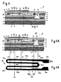
- Figs. 3A and 3B are views showing the shape and arrangement of a heater
- Fig. 4 is a partially-enlarged view of Fig. 1 ;
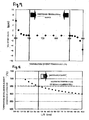
- Fig. 5 is a view showing changes in offset value with a change in the temperature of a second pumping cell
- Fig. 6 is a view showing changes in NOx gain with a change in the temperature of the second pumping cell
- Fig. 7 is a view showing changes in offset value achieved with a change in the temperature of a first pumping cell.
- Fig. 8 is a view showing the temperature of a position L/2 achieved with a change in the length L/2 of the NOx sensor element.
- Fig. 1 shows a cross-sectional view of a gas sensor (an NOx sensor) 200 of a first exemplary embodiment of the present invention taken along a longitudinal direction.
- the NOx sensor 200 has cylindrical metal shell 138, an exterior surface of which is formed into a thread 139 to be fastened to an exhaust pipe; an NOx sensor element (a gas sensor element) 10 assuming the shape of a plate extending in an axial direction (a longitudinal direction of the NOx sensor 200: a vertical direction in the drawing); a cylindrical ceramic sleeve 106 positioned so as to surround a radial circumference of the NOx sensor element 10; an insulating contact member 166 in which an interior wall surface of a contact insertion hole 168 penetrating through the insulating contact member in an axial direction is arranged so as to surround the circumference of a rear end of the NOx sensor element; and six connection terminals 110 (four connection terminals are illustrated in Fig. 1 ) interposed between the NOx sensor element 10 and the respective insulation contact members 166
- the metal shell 138 is configured into an essentially-cylindrical shape so as to have a through hole 154 penetrating through the metal shell in an axial direction and a shelf 152 inwardly projecting along the radial direction of the through hole 154.
- a leading end of the NOx sensor element 10 is positioned outside the leading end side of the through hole 154, and electrode terminal sections 220 and 221 are held in the through hole 154 while positioned outside a rear end side of the through hole 154.
- the shelf 152 is formed as an interiorly-oriented tapered surface that is inclined with respect to a perpendicular plane along the axial direction.
- An annular ceramic holder 151, powder-packed layers 153 and 156 (also called talc rings 153 and 156), and the foregoing ceramic sleeve 106 are stacked, in this sequence from the leading end side to the rear end side, within the through hole 154 of the metal shell 138 while surrounding the radial circumference of the NOx sensor clement 10.
- a crimp packing 157 is interposed between the ceramic sleeve 106 and a rear end section 140 of the metal shell 138.
- a metal holder 158 that holds the talc ring 153 and the ceramic holder 151 and that maintains airtightness is interposed between the ceramic holder 151 and the shelf 152 of the metal shell 138.
- the rear end section 140 of the metal shell 138 is crimped so as to press the ceramic sleeve 106 toward the leading end side by way of the crimping packing 157.
- the NOx sensor element 10 is fastened by means of the ceramic holder 151, or the like, that constitutes the housing of the gas sensor 200, and the NOx sensor element 10 protrudes from a lower surface of the ceramic holder 151. Accordingly, an area of the NOx sensor element 10 located at the same position where the lower surface of the ceramic holder 151 is situated is taken as a stationary end 10b.
- an outer metal protector 142 and an inner metal protector 143 which cover a projecting portion of the NOx sensor element 10 and which have a plurality of pores, are doubly attached to an outer periphery of the leading end (a lower portion shown in Fig. 1 ) of the metal shell 138 by means of welding or the like.
- An outer sheath 144 is fixed to an outer periphery of the rear end of the metal shell 138.
- a grommet 150 is disposed in an opening of the rear end side (an upper position in Fig. 1 ) of the outer sheath 144.
- the grommet 150 has lead wire insertion holes 161 into which six lead wires 146 (only five of them are shown in Fig. 1 ) electrically connected to the electrode terminal sections 220 and 221 of the NOx sensor element 10 are inserted.
- An insulating contact member 166 is positioned at the rear end (an upper portion shown in Fig. 1 ) of the NOx sensor element 10 projecting out of the rear end 140 of the metal shell 138.
- the insulating contact member 166 is placed around the electrode terminal sections 220 and 221 formed on the surface of the rear end of the NOx sensor element 10.
- the insulating contact member 166 is formed into a cylindrical shape having a contact insertion hole 168 that penetrates through the insulating contact member in the axial direction, and also has a collar 167 projecting from an outer surface of the insulating contact member 166 to the radial outside.
- the insulating contact member 166 is positioned within the outer sheath 144 as a result of the collar 167 contacting the outer sheath 144 by way of a holding member 169.
- the structure of the NOx sensor element 10 will now be described by reference to a cross-sectional view of Fig. 2 taken along a longitudinal direction.
- the term "longitudinal direction" means a longitudinal direction of the NOx sensor element and a direction perpendicular to a direction in which the respective layers of the NOx sensor element are stacked.
- the NOx sensor element 10 has a structure in which a first solid electrolytic layer 11 a, an insulation layer 14a, a second solid electrolytic layer 12a, an insulation layer 14b, a third solid electrolytic layer 13a, and insulation layers 14c and 14d are stacked in this sequence.
- a first measurement chamber 16 is partitioned between the first solid electrolytic layer 11a and the second solid electrolytic layer 12a.
- a gas to be measured GM is introduced from the outside by way of a first diffusive resistance element 15a positioned at the left end (an entrance) of the first measurement chamber 16.
- a second diffusive resistance element 15b is positioned at a location on the first measurement chamber 16 opposite the entrance.
- a second measurement chamber 18 in mutual communication with the first measurement chamber 16 is partitioned in an area on the right side of the first measurement chamber 16 by way of the second diffusive resistance element 15b.
- the second measurement chamber 18 is formed between the first solid electrolytic layer 11a and the third solid electrolytic layer 13a while penetrating through the second solid electrolytic layer 12a.
- An elongated plate-shaped heater 50 that extends along the longitudinal direction of the NOx sensor element 10 is embedded between the insulation layers 14c and 14d.
- the heater 50 heats the gas sensor to an activation temperature and enhances conductivity of oxygen ions in the solid electrolytic layer, to thereby stabilize operation.
- the insulation layers 14a to 14d are primarily made of alumina, and the first diffusive resistance element 15a and the second diffusive resistance element 15b are made of a porous substance, such as alumina.
- the heater 50 is made of platinum, or the like.
- a first pumping cell 11 has a first solid electrolytic layer 11a primarily made of zirconia exhibiting oxygen ion conductivity, and a first interior pump electrode 11c and a first counterpart electrode (a first exterior pump electrode) 11b which are positioned such that the first solid electrolytic layer 11a is sandwiched between the electrodes 11b and 11c; and the first interior pump electrode 11c faces the first measurement chamber 16.
- Both the first interior pump electrode 11c and the first exterior pump electrode 11b are primarily made of platinum, and the surfaces of the respective electrodes are coated with protective layers 11e and 11d made of a porous substance.
- An oxygen concentration detection cell 12 has a second solid electrolytic layer 12a primarily made of zirconia, and a detection electrode 12b and a reference electrode 12c disposed such that the electrolytic layer 12a is sandwiched between the electrodes 12b and 12c.
- the detection electrode 12b is located downstream of the first interior pump electrode 11c and faces the first measurement chamber 16. Both the detection electrode 12b and the reference electrode 12c are primarily made of platinum.
- a cutout is formed in the insulation layer 14b such that the reference electrode 12c contacting the second solid electrolytic layer 12a is disposed therein. Further, the resultant space is filled with a porous substance, thereby constituting a reference oxygen chamber 17. A predetermined feeble current is preliminarily passed through to the oxygen concentration detection cell 12. In this manner, oxygen is supplied to the reference oxygen chamber 17 from the first measurement chamber 16, to thereby provide an oxygen standard.
- the second pumping cell 13 has a third solid electrolytic layer 13a primarily made of zirconia, a second interior pump electrode 13b, and a second counterpart electrode 13c which is a counterpart electrode of the second interior pump electrode 13b.
- the second interior pump electrode 13b that is placed at an area on the surface of the third solid electrolytic layer 13a facing the second measurement chamber 18
- Both the second interior pump electrode 13b and the second counterpart pump electrode 13c are primarily made of platinum.
- the second counterpart pump electrode 13c is placed at a cutout of the insulation layer 14b on the third solid electrolytic layer 13a and faces the reference oxygen chamber 17 while positioned opposite the reference electrode 12c.
- the second interior electrode pump 13b does not overlap the first interior pump electrode 11c and the first exterior pump electrode 11b along the longitudinal direction.
- an aspect of the present invention resides in controlling the temperature of the second interior pump electrode 13b (i.e., the second pumping cell 13) so as to become lower than the temperature of the first pumping cell 11 and in separately controlling the temperature of the first pumping cell 11 and the temperature of the second pumping cell 13.
- the heater 50 is activated by way of a predetermined control circuit, thereby heating the first pumping cell 11, the oxygen concentration detection cell 12, and the second pumping cell 13 to an activation temperature.
- the first pumping cell 11 pumps excess oxygen in the gas to be measured (an exhaust gas) GM, which has flowed into the first measurement chamber 16, from the first interior pump electrode 11c toward the first counterpart electrode 11b.
- an interelectrode voltage (a terminal voltage) Vs of the oxygen concentration detection cell 12 is controlled such that the interelectrode voltage Vs becomes a constant voltage V1 (e.g., 425 mV), thereby adjusting (generally, lowering) the concentration of oxygen in the first measurement chamber 16 to an extent at which NOx is not decomposed.
- the gas to be measured GN whose oxygen concentration has been adjusted further flows toward the second measurement chamber 18.
- a constant voltage Vp2 (a voltage that is higher than a control voltage of the oxygen concentration detection cell 12; for instance, 450 mV) at which the NOx gas in the gas to be measured GN is decomposed into oxygen and an N 2 gas is applied as an interelectrode voltage (a terminal voltage) Vp2 of the second pumping cell 13, whereupon NOx is decomposed into nitrogen and oxygen.
- a second pump current Ip2 flows into the second pumping cell 13 in such a way that the oxygen resulting from decomposition of NOx is pumped out of the second measurement clamber 18. Since a linear relationship exists between the second pump current Ip2 and the NOx concentration at this time, the NOx concentration in the gas to be measured can be detected by monitoring Ip2.
- Fig. 3 shows the shape and layout of the heater.
- Fig. 3A shows a cross-sectional view of the NOx sensor element 10 identical to that of Fig. 2.
- Fig. 3B shows a plan view of a heater 50.
- Straight lines A1, A2, A3, A4 and He extending between Figs. 3A and 3B show a positional correspondence between respective constituent elements of the NOx sensor element 10 and the heater 50.
- the heater 50 is constructed by connecting together lead portions 50a, straight resistance portions 50b and 50b1 extending in a longitudinal direction (identical with the longitudinal direction of the NOx sensor element 10), and bends 50c1 and 50c2 coupling the two adjacent straight resistance portions.
- one lead portion 50a is connected to a lead-end side bent portion 50c1 by way of the straight resistance portion 50b1.
- the leading-end side bend 50c1 which has a reverse bend in the longitudinal direction, is connected to the straight resistance portion 50b.
- the straight resistance portion 50b is connected to the rear-end side bend 50c2.
- the other straight resistance portion 50b is connected to the other leading-end side bend 50c1.
- the other leading-end side bend 50c1, which has reverse bend in the longitudinal direction is connected to the other straight resistance portion 50b1, and the other straight resistance portion 50b1 is connected to the other lead portion 50a.
- the straight resistance portion 50b1 is connected to the lead portion 50a and has a first resistance portion 50bx whose width is narrower than that of the lead portion 50a.
- the second interior pump electrode 13b is situated so as to be aligned within the first resistance portion 50bx in the longitudinal direction. More specifically, the leading end and the trailing end of the second interior pump electrode 13b overlap the first resistance portion 50bx in the longitudinal direction (corresponding to A1 and A2 in Fig. 3 ). A center P of the second interior pump electrode 13b with respect to the longitudinal direction also overlaps the first resistance portion 50bx in the longitudinal direction.
- the first resistance portion 50bx can control the temperature of the second interior pump electrode 13b by situating the second interior pump electrode 13b within the first resistance portion 50bx.
- the second counterpart pump electrode 13c is located outside the projection of the first resistance portion 50bx. However, the location where NOx, H 2 O and other gases are decomposed is above the second interior pump electrode 13b. Hence, the essential requirement is to control the temperature of the second interior pump electrode 13b.
- the first resistance portion 50bx becomes higher than the lead portion 50a in terms of resistance as a result of the first resistance portion 50bx being made narrower than the lead portion 50a, the first resistance portion 50bx is reliably heated, so that the second interior pump electrode 13b can be controlled to a predetermined temperature.
- the first resistance portion 50bx is connected to a main heating portion 50k, and the main heating portion 50k extends over the straight resistance portions 50b and 50b1 and the bends 50c1 and 50c2.
- the main heating portion 50k has a second resistance portion 50by located ahead of the leading end (a position B in Fig. 3 ) of the first resistance portion 50bx and a third resistance portion 50i located behind the leading end of the first resistance portion 50bx.
- the second resistance portion 50by is made narrower than the first resistance portion 50bx and overlaps the first interior pump electrode 11c in the longitudinal direction. More specifically, the leading end and the trailing end of the first interior pump electrode 11c overlap the second resistance portion 50by in the longitudinal direction (as indicated by A3 and A4 in Fig. 3 ).
- the second resistance portion 50by As a result of the second resistance portion 50by being made narrower than the first resistance portion 50bx as mentioned above, the second resistance portion 50by has a higher resistance than the first resistance portion 50bx, whereby the heating action of the second resistance portion 50by is more intense. Hence, the temperature of the first resistance portion 50bx can be set so as to become lower than the temperature of the second resistance portion 50by. Consequently, the second interior pump electrode 13b is controlled to a lower temperature, to thereby prevent the occurrence of variations in offset value.
- leading end and the trailing end of the second interior pump electrode 13b desirably overlap the first resistance portion 50bx in the longitudinal direction.
- the entirety of the second interior pump electrode 13b overlaps the first resistance portion 50bx in the longitudinal direction, so that the temperature of the second interior pump electrode 13b can be controlled more reliably by the first resistance portion 50bx.
- leading end and the trailing end of the first interior pump electrode 11c desirably overlap the second resistance portion 50by in the longitudinal direction.
- the entirety of the first interior pump electrode 11c overlaps the second resistance portion 50by in the longitudinal direction. In this manner, it becomes possible to further prevent the occurrence of a deficiency in oxygen pumping capability and variations in offset value, which would otherwise occur when the temperature of the first pumping cell 11 becomes lower.
- the respective bends 50c1 and 50c2 are present among the longitudinally-extended straight resistance portions 50b and 50b1. Therefore, when compared with a case where the straight resistance portions extend in the widthwise direction of the NOx sensor element 10 which is shorter than the longitudinal direction of the NOx sensor element 10 (50t in Fig. 3B ), the lengths of the straight resistance portions 50b and 50b1 are made comparatively longer, and the number of bends can be reduced accordingly. Hence, there is little chance of local overheating arising in the bends 50c1 and 50c2, so that the durability of the heater 50 can be enhanced.
- changing the thickness the heater 50 and changing the material of the heater 50 are also possible as a method for changing the resistance of the respective sections of the heater 50.
- two or more of these methods may be combined together.
- Adding a component exhibiting high electrical conductivity (low specific resistance) to the material of the heater 50 for instance, adding Au or Ag to Pt that is the principal constituent of the heater 50, to thus reduce resistance, can be mentioned as a method for changing the material of the heater 50.
- adding a component exhibiting low electrical conductivity (large specific resistance) to the material of the heater 50 for instance, adding one or more of aluminum, zirconia, ceria, yttria, Rh, Pd, Ir, Ru, Os, and Cu to Pt that is the principal constituent of the heater 50, to thus increase resistance, can also be mentioned.
- a heating center Hc of the heater 50 be situated at the straight resistance portions 50b1 and 50b in the second resistance portion 50by in the longitudinal direction.
- the center area of the heater 50 is usually hottest, and the temperature of the heater decreases with increasing distance toward an edge of the heater.
- the bends 50c1 and 50c2 are not present in the heating center Hc of the heater 50 that becomes hottest. In this manner, the occurrence of local overheating in the bends 50c1 and 50c2 is further inhibited and durability of the heater 50 can be further enhanced. Moreover, since the heating center Hc is present in the straight resistance portions 50b1 and 50b, heat is dissipated to a certain extent while the heat is transferred from the heating center Hc to the bends 50c1 and 50c2, whereupon overheating of the bends 50c1 and 50c2 is prevented.
- the third resistance portion 50i of the main heating portion 50k is lower in resistance than the second resistance portion 50by and higher in resistance than the lead portion 50a.
- the third resistance portion 50i situated within the second interior pump electrode 13b is also made higher in resistance than the lead portion 50a.
- the third resistance portion 50i is reliably heated, and the second interior pump electrode 13b can be controlled to a predetermined temperature.
- the temperature of the third resistance portion 50i can be made lower than the second resistance portion 50by.
- the second interior pump electrode 13b can be controlled to a lower temperature, whereby the occurrence of variations in offset value can be prevented.
- the present inventors found that when the temperature of the second pumping cell 13 exceeds 650°C, a second pump current Ip2 resulting from dissociation of water develops, which in turn causes further variation in offset value. For this reason, the heater 50 is desirably controlled such that the temperature of the second interior pump electrode 13b constituting the second pumping cell 13 is maintained at 400 to 650°C.
- the reason for increasing the temperature of the second pumping cell 13 to 400°C or higher is that when the temperature decreases to 400°C or lower, the NOx dissolving power of the second interior pump electrode 13b becomes deficient.
- the present inventors found that, when the temperature of the first pumping cell 11 exceeds 850°C, electron conduction of the solid electrolytic layer is enhanced, thereby decreasing the offset value. For this reason, it is preferable to control the heater 50 such that the temperature of the first pumping cell 11 is maintained at 700 to 850°C.
- the reason for increasing the temperature of the first pumping cell 11 to 700°C or higher is that, when the temperature is decreased to 700°C or lower, ion conductivity of the solid electrolytic layer is decreased, which in turn results in a deficiency in oxygen pumping capability.
- Fig. 4 is a partially-enlarged view of Fig. 1 , showing a positional relationship between the housing (the ceramic holder 151) of the NOx sensor and the gas sensor element 10.
- a distance from the stationary end 10b of the NOx sensor element to the center P of the second interior pump electrode 13b in the longitudinal direction of the NOx sensor element 10 is taken as L and that the thickness of the NOx sensor element is taken as "t," a relationship of L ⁇ 2.4 ⁇ t is preferably satisfied.
- a hot gas to be measured (an exhaust gas) transfers heat from the outside (Hex: the collar of the metal shell 138) of the NOx sensor 10 to the NOx sensor element hold section (the ceramic holder 151) in the housing, and the heat further travels to the NOx sensor element 10. Accordingly, in order to prevent the second pumping cell 13 from being heated by the heat transferred from the gas to be measured, the distance from the ceramic holder 151 to the second interior pump electrode 13b is preferably made longer.
- the present inventors found that when a relationship of L ⁇ 2.4 ⁇ t is satisfied, an increase in the temperature of the second pumping cell 13 can be prevented even when the second pumping cell is exposed to the hot gas to be measured.
- An NOx sensor 200 of a first exemplary embodiment was manufactured according to an ordinary method.
- the heater 50 was made by applying a paste principally made of Pt and sintering the paste, and the resistance of respective sections of the heater 50 was changed by changing the line widths of the heater 50.
- Power was applied to the heater 50 by use of the NOx sensor 200, thereby controlling the voltage of the heater such that the temperature of the second pumping cell 13 (the second interior pump electrode 13b) reached a predetermined temperature.
- an output of the second pump current Ip2 was acquired for 30 seconds while a total quantity of 18 liters of a gas containing 0% O 2 , 10% H 2 O and a balance of N 2 (a gas temperature of 120°C) was caused to flow to the sensor. Then, an average of the outputs was taken as an offset value (an offset current).
- Fig. 5 shows the variation in offset value with a change in temperature of the second pumping cell 13. As shown in Fig. 5 , an offset current starts to flow when the temperature of the second pumping cell 13 exceeds 650°C. This is conceivably ascribable to dissociation of water present in the gas.
- the output of the second pump current Ip2 was acquired for 30 seconds in the same manner as in Example 1, except that the gas component was changed to 0% O 2 , 0.1% H 2 O, 100 ppm NO and a balance of N 2 , and an average of the output was taken as an NOx gain.
- Fig. 6 shows the change in NOx gain with a change in the temperature of the second pumping cell 13. As shown in Fig. 6 , when the temperature of the second pumping cell 13 was less than 400°C, a decrease in NOx gain and a reduction in NOx decomposition power of the second pumping cell 13 was observed.
- the temperature of the second pumping cell 13 is preferably controlled to 400 to 650°C.
- the output of the second pump current Ip2 was acquired for 30 seconds in the same manner as in Example 1, except that the gas component was changed to 0.1% H 2 O, 16% O 2 and a balance of N 2 ; except that the temperature of the second pumping cell 13 was held constant at a 580°C; and except that the temperature of the first pumping cell 11 was changed. An average of the output was taken as an offset value.
- Fig. 7 shows the change in offset value with a change in the temperature of the first pumping cell 11.
- the offset current increased.
- the reason for this is a deficiency in oxygen pumping capability.
- the temperature of the first pumping cell 11 exceeded 850°C, the offset current decreased.
- the gradient of oxygen concentration in the first measurement chamber abruptly increased. This is because oxygen pumping performed on an output side (the trailing end) became predominant as a result of an increase in contribution of electron conduction of an input side (a leading end side) of the first pumping cell 11.
- the temperature of the first pumping cell 11 is preferably controlled to 700 to 850°C.
- a plurality of NOx sensors were manufactured in the same manner as in Example 1, with variously changing the length L of the NOx sensor element. After ten minutes had elapsed during which the outside of the Hex (the metal shell 138) of each of the NOx sensors was held at 500°C, the temperature of a position spaced the length L was measured. In relation to the dimension of the ceramic holder 151, the diameter of the ceramic holder is 10.4 mm, and an axial length of the same is about 4.6 mm; and the thickness "t" of the NOx sensor element is 1.5 mm.
- Table 8 shows the thus-acquired results.
- L 3.5 mm or greater
- the temperature of the second pumping cell 13 dropped to 650°C or less. From these results, the relationship L ⁇ 2.4 ⁇ t is preferably satisfied.
- planar geometry of the heater is not limited to those mentioned above.
- the solid electrolytic layers 11a, 12a and 13a that constitute the NOx sensor element 10 are embodied as three layers; however, the layers may also be embodied as two layers.
- the structure of an NOx sensor element having two solid electrolytic layers is described, for instance, in JP-A-2004-354400 ( Fig. 3 ).
- the present invention can be applied to a gas sensor for detecting the concentration of NOx gas in an exhaust gas from an automobile or various internal combustion engines or a combustion gas from a boiler, an oxygen sensor such as an all range air-fuel sensor, or the like, and the invention is not limited to these applications.
- the present invention can also be applied to a gas sensor having a gas sensor element for measuring the concentration of a gas (e.g., CO x , H 2 O, HC, or the like) other than NOx.
- a gas e.g., CO x , H 2 O, HC, or the like
- a gas sensor comprising a longitudinally-extending gas sensor element.
- the gas sensor element has a first measurement chamber that is partitioned between two solid electrolytic layers stacked with a space therebetween and into which a gas to be measured is introduced from outside the gas sensor; a first pumping cell that has a first interior pump electrode facing the first measurement chamber and a first counterpart electrode serving as a counterpart electrode of the first interior pump electrode, the first pumping cell controlling oxygen partial pressure in the first measurement chamber; a second measurement chamber partitioned from surroundings and in mutual communication with the first measurement chamber and into which a gas to be measured having a controlled oxygen partial pressure is introduced from the first measurement chamber; a second pumping cell having an interior second pumping electrode disposed within the second measurement chamber and a second counterpart electrode of the second interior pump electrode and that detects a specific gas component in the gas to be measured within the second measurement chamber; and a heater that is positioned along a direction in which the solid electrolytic layers are stacked and that heats the first pumping cell and the second
- the second interior pump electrode and the first resistance portion overlap each other in the longitudinal direction, so that the temperature of the second interior pump electrode (i.e., the second pumping cell) can be controlled by the first resistance portion.
- the first resistance portion and the lead section have the same resistance, the first resistance portion will not generate heat.
- the first resistance portion is influenced by the external temperature, which makes it difficult to control the second interior pump electrode to a predetermined temperature.
- the first resistance portion is made to have a higher resistance than the lead portion. Hence, the first resistance portion reliably generates heat, whereby the second interior pump electrode can be controlled to a predetermined temperature.
- the second resistance portion is made to have a higher resistance than the first resistance portion, heat generation of the second resistance portion becomes more intensive, and the temperature of the first resistance portion can be made lower than the temperature of the second resistance portion. Consequently, the temperature of the second interior pump electrode is controlled to a low temperature, so that the occurrence of variations in offset value can be prevented.
- the occurrence of variations in offset value (which would otherwise arise when oxygen pumping capability becomes deficient as a result of the temperature of the first pumping cell overlapping the second resistance portion in the longitudinal direction becoming lower) can be prevented by increasing the temperature of the second resistance portion.
- resistance means resistance per unit length.
- leading end side in a longitudinal direction means to a side that is closer to the first pumping cell than to the second pumping cell when viewed in the longitudinal direction.
- the word “behind in a longitudinal direction” refers to a direction opposite that side.
- the leading end and the trailing end of the second interior pump electrode preferably overlap the first resistance portion in the longitudinal direction.
- the entirety of the second interior pump electrode overlaps the first resistance portion in the longitudinal direction.
- the leading end and the trailing end of the first interior pump electrode preferably overlap the second resistance portion in the longitudinal direction.
- the entirety of the first interior pump electrode overlaps the second resistance portion in the longitudinal direction, whereby the occurrence of variations in offset value, which would otherwise arise when oxygen pumping capability becomes deficient as a result of the temperature of the first pumping cell becoming lower, can be further prevented.
- the heater is preferably made by coupling at least two or more straight resistance portions extending in the longitudinal direction to a bend that connects the two adjacent straight resistance portions; and the first resistance portion is placed in the straight resistance portion that is positioned outermost in a widthwise direction perpendicular to the longitudinal direction.
- the straight resistance portion when compared with a case where a straight resistance section extends in a widthwise direction of the NOx sensor element 10 which is shorter than the longitudinal direction of the NOx sensor element 10, the straight resistance portion can be made comparatively longer, and the number of bends can be reduced accordingly. Hence, the chance of occurrence of local heat generation of the bend becomes small, and durability of the heater can be enhanced.
- the heating center of the heater in the longitudinal direction is preferably situated in the straight resistance portion within the second resistance portion.
- the bend is not situated at the heating center of the heater where the highest heat is realized. Hence, local overheating in the bend is further inhibited, and durability of the heater can be further enhanced. Moreover, since the heating center lies in the straight resistance portion, heat is dissipated to a certain extent during a period in which heat transfers from the heating center to the bend, so that overheating of the bend is prevented.
- the heating center of the heater refers to the maximum temperature area of the heater when viewed from a certain direction.
- the center of the heater is usually hottest, and the temperature decreases with increasing distance from the center to a periphery of the heater.
- the main heating section preferably has a third resistance portion that is positioned behind a leading end of the first resistance portion in the longitudinal direction, and the third resistance portion has a lower resistance than the second resistance portion and has a higher resistance than the lead section.
- the resistance of the heater is preferably changed by changing at least one or more of a line width, a thickness, and a material of the heater. This makes it possible to readily change the resistance of the heater (resistance per unit length).
- the leading end of the gas sensor element in the longitudinal direction is preferably fixed so as to protrude from a housing side of the gas sensor, and a relationship of L ⁇ 2.4 ⁇ t is preferably satisfied, provided that a length from a stationary end of the gas sensor element to a center of the second pump electrode in the longitudinal direction is taken as L and that the thickness of the gas sensor element is taken as "t.”
- the distance from the stationary section of the gas sensor element to the center (the position L) of the second pump electrode is preferably made longer.
Landscapes
- Chemical & Material Sciences (AREA)
- Life Sciences & Earth Sciences (AREA)
- Health & Medical Sciences (AREA)
- Physics & Mathematics (AREA)
- Chemical Kinetics & Catalysis (AREA)
- Electrochemistry (AREA)
- Molecular Biology (AREA)
- Analytical Chemistry (AREA)
- Biochemistry (AREA)
- General Health & Medical Sciences (AREA)
- General Physics & Mathematics (AREA)
- Immunology (AREA)
- Pathology (AREA)
- Measuring Oxygen Concentration In Cells (AREA)
Applications Claiming Priority (2)
| Application Number | Priority Date | Filing Date | Title |
|---|---|---|---|
| JP2008095640 | 2008-04-02 | ||
| JP2009036296A JP4659889B2 (ja) | 2008-04-02 | 2009-02-19 | ガスセンサ |
Publications (2)
| Publication Number | Publication Date |
|---|---|
| EP2107364A1 true EP2107364A1 (fr) | 2009-10-07 |
| EP2107364B1 EP2107364B1 (fr) | 2015-07-08 |
Family
ID=40723129
Family Applications (1)
| Application Number | Title | Priority Date | Filing Date |
|---|---|---|---|
| EP09004846.3A Active EP2107364B1 (fr) | 2008-04-02 | 2009-04-01 | Capteur de gaz |
Country Status (3)
| Country | Link |
|---|---|
| US (1) | US8118985B2 (fr) |
| EP (1) | EP2107364B1 (fr) |
| JP (1) | JP4659889B2 (fr) |
Cited By (4)
| Publication number | Priority date | Publication date | Assignee | Title |
|---|---|---|---|---|
| US10527578B2 (en) | 2015-08-21 | 2020-01-07 | Ngk Insulators, Ltd. | Ceramic heater, sensor element, and gas sensor |
| US10712307B2 (en) | 2015-08-21 | 2020-07-14 | Ngk Insulators, Ltd. | Ceramic heater, sensor element, and gas sensor |
| US10837937B2 (en) | 2015-08-21 | 2020-11-17 | Ngk Insulators, Ltd. | Ceramic heater, sensor element, and gas sensor |
| DE112015002843B4 (de) | 2014-06-16 | 2023-06-15 | Denso Corporation | Gassensor |
Families Citing this family (13)
| Publication number | Priority date | Publication date | Assignee | Title |
|---|---|---|---|---|
| US7719523B2 (en) | 2004-08-06 | 2010-05-18 | Touchtable, Inc. | Bounding box gesture recognition on a touch detecting interactive display |
| US9217654B2 (en) * | 2010-09-15 | 2015-12-22 | General Electric Company | Submetering hydrocarbon fueled water heaters with energy manager systems |
| KR102041205B1 (ko) * | 2013-03-18 | 2019-11-06 | 주식회사 미코바이오메드 | 패턴 히터가 반복 배치된 pcr 열 블록 및 이를 포함하는 pcr 장치 |
| JP6321968B2 (ja) * | 2014-01-17 | 2018-05-09 | 株式会社Soken | ガスセンサ素子 |
| JP5939265B2 (ja) | 2014-02-11 | 2016-06-22 | 株式会社デンソー | セラミックヒータ及びこれを用いたガスセンサ素子 |
| JP6561719B2 (ja) * | 2014-10-30 | 2019-08-21 | 株式会社デンソー | ガスセンサ |
| WO2016067975A1 (fr) * | 2014-10-30 | 2016-05-06 | 株式会社デンソー | Capteur de gaz |
| JP6485364B2 (ja) | 2015-02-12 | 2019-03-20 | 株式会社デンソー | ガスセンサ |
| WO2016129661A1 (fr) * | 2015-02-12 | 2016-08-18 | 株式会社デンソー | Capteur de gaz |
| JP6674211B2 (ja) * | 2015-08-21 | 2020-04-01 | 日本碍子株式会社 | セラミックスヒータ,センサ素子及びガスセンサ |
| JP6584219B2 (ja) * | 2015-08-21 | 2019-10-02 | 日本碍子株式会社 | セラミックスヒータ,センサ素子及びガスセンサ |
| JP2017078579A (ja) * | 2015-10-19 | 2017-04-27 | 株式会社デンソー | 排出ガスセンサの制御装置及び排出ガスセンサシステム |
| JP7078584B2 (ja) * | 2019-09-03 | 2022-05-31 | 日本碍子株式会社 | セラミックスヒータ,センサ素子及びガスセンサ |
Citations (6)
| Publication number | Priority date | Publication date | Assignee | Title |
|---|---|---|---|---|
| EP0880026A1 (fr) * | 1997-05-20 | 1998-11-25 | Ngk Insulators, Ltd. | Capteur de gaz |
| EP0884587A1 (fr) * | 1997-06-13 | 1998-12-16 | NGK Spark Plug Co. Ltd. | Appareil pour déterminer la concentration de NOx |
| DE19827469A1 (de) * | 1997-06-20 | 1999-01-07 | Denso Corp | Gaskonzentrationsmeßverfahren und ein vorteilhafterweise bei dieser Messung verwendeter Verbundgassensor |
| EP1217365A2 (fr) * | 2000-12-22 | 2002-06-26 | Siemens Aktiengesellschaft | Système de détecteurs multiples de gaz avec référence de gaz |
| WO2003060502A1 (fr) * | 2002-01-03 | 2003-07-24 | Robert Bosch Gmbh | Element detecteur |
| JP2004354400A (ja) | 2004-09-22 | 2004-12-16 | Ngk Insulators Ltd | ガスセンサ及び窒素酸化物センサ |
Family Cites Families (6)
| Publication number | Priority date | Publication date | Assignee | Title |
|---|---|---|---|---|
| JPS60259951A (ja) * | 1984-06-06 | 1985-12-23 | Ngk Insulators Ltd | 電気化学的素子 |
| DE19803562B4 (de) * | 1998-01-30 | 2011-06-01 | Robert Bosch Gmbh | Sensorelement |
| JP2004151017A (ja) * | 2002-10-31 | 2004-05-27 | Denso Corp | 積層型ガスセンサ素子 |
| JP4304963B2 (ja) * | 2002-11-08 | 2009-07-29 | 株式会社デンソー | ガスセンサ素子およびその製造方法 |
| JP4355306B2 (ja) * | 2005-07-01 | 2009-10-28 | 日本特殊陶業株式会社 | ガスセンサ |
| JP4855756B2 (ja) * | 2005-10-13 | 2012-01-18 | 株式会社デンソー | ガスセンサ素子 |
-
2009
- 2009-02-19 JP JP2009036296A patent/JP4659889B2/ja active Active
- 2009-04-01 EP EP09004846.3A patent/EP2107364B1/fr active Active
- 2009-04-02 US US12/417,074 patent/US8118985B2/en active Active
Patent Citations (6)
| Publication number | Priority date | Publication date | Assignee | Title |
|---|---|---|---|---|
| EP0880026A1 (fr) * | 1997-05-20 | 1998-11-25 | Ngk Insulators, Ltd. | Capteur de gaz |
| EP0884587A1 (fr) * | 1997-06-13 | 1998-12-16 | NGK Spark Plug Co. Ltd. | Appareil pour déterminer la concentration de NOx |
| DE19827469A1 (de) * | 1997-06-20 | 1999-01-07 | Denso Corp | Gaskonzentrationsmeßverfahren und ein vorteilhafterweise bei dieser Messung verwendeter Verbundgassensor |
| EP1217365A2 (fr) * | 2000-12-22 | 2002-06-26 | Siemens Aktiengesellschaft | Système de détecteurs multiples de gaz avec référence de gaz |
| WO2003060502A1 (fr) * | 2002-01-03 | 2003-07-24 | Robert Bosch Gmbh | Element detecteur |
| JP2004354400A (ja) | 2004-09-22 | 2004-12-16 | Ngk Insulators Ltd | ガスセンサ及び窒素酸化物センサ |
Cited By (7)
| Publication number | Priority date | Publication date | Assignee | Title |
|---|---|---|---|---|
| DE112015002843B4 (de) | 2014-06-16 | 2023-06-15 | Denso Corporation | Gassensor |
| US10527578B2 (en) | 2015-08-21 | 2020-01-07 | Ngk Insulators, Ltd. | Ceramic heater, sensor element, and gas sensor |
| US10712307B2 (en) | 2015-08-21 | 2020-07-14 | Ngk Insulators, Ltd. | Ceramic heater, sensor element, and gas sensor |
| US10837937B2 (en) | 2015-08-21 | 2020-11-17 | Ngk Insulators, Ltd. | Ceramic heater, sensor element, and gas sensor |
| US11567032B2 (en) | 2015-08-21 | 2023-01-31 | Ngk Insulators, Ltd. | Ceramic heater, sensor element, and gas sensor |
| DE102016215507B4 (de) | 2015-08-21 | 2023-06-07 | Ngk Insulators, Ltd. | Keramisches heizelement, sensorelement und gassensor |
| US11768169B2 (en) | 2015-08-21 | 2023-09-26 | Ngk Insulators, Ltd. | Ceramic heater, sensor element, and gas sensor |
Also Published As
| Publication number | Publication date |
|---|---|
| JP2009265085A (ja) | 2009-11-12 |
| JP4659889B2 (ja) | 2011-03-30 |
| EP2107364B1 (fr) | 2015-07-08 |
| US8118985B2 (en) | 2012-02-21 |
| US20090250344A1 (en) | 2009-10-08 |
Similar Documents
| Publication | Publication Date | Title |
|---|---|---|
| EP2107364B1 (fr) | Capteur de gaz | |
| US9829462B2 (en) | Gas sensor element and gas sensor | |
| US9032779B2 (en) | Gas sensor | |
| US9719957B2 (en) | Gas sensor element and gas sensor | |
| US8431002B2 (en) | Gas sensor | |
| US10690621B2 (en) | Sensor element for detecting at least one property of a measuring gas in a measuring gas chamber | |
| CN105765377B (zh) | 氧传感器元件 | |
| JP4965356B2 (ja) | ガスセンサの劣化判定方法 | |
| US10775342B2 (en) | Gas sensor | |
| US10996193B2 (en) | Gas sensor element and gas sensor | |
| US8127594B2 (en) | Gas sensor | |
| US10908116B2 (en) | Gas sensor | |
| US20190277796A1 (en) | Sensor and method of manufacturing sensor | |
| JP5139955B2 (ja) | セラミックヒータ、ガスセンサ素子及びガスセンサ | |
| JP6726604B2 (ja) | ガスセンサ | |
| US20190162693A1 (en) | Sensor element and gas sensor including the same | |
| JP4758325B2 (ja) | ガスセンサ素子、ガスセンサ及びNOxセンサ | |
| US11604160B2 (en) | Gas sensor | |
| JP6979387B2 (ja) | センサ素子及びガスセンサ | |
| JP2022147914A (ja) | ガスセンサ | |
| JP3771018B2 (ja) | ガス濃度検出素子 | |
| US20190302050A1 (en) | Gas sensor element, heater and gas sensor | |
| JP6943575B2 (ja) | ガスセンサ | |
| JP7391638B2 (ja) | センサ素子及びガスセンサ | |
| JP6438851B2 (ja) | ガスセンサ素子及びガスセンサ |
Legal Events
| Date | Code | Title | Description |
|---|---|---|---|
| PUAI | Public reference made under article 153(3) epc to a published international application that has entered the european phase |
Free format text: ORIGINAL CODE: 0009012 |
|
| AK | Designated contracting states |
Kind code of ref document: A1 Designated state(s): AT BE BG CH CY CZ DE DK EE ES FI FR GB GR HR HU IE IS IT LI LT LU LV MC MK MT NL NO PL PT RO SE SI SK TR |
|
| 17P | Request for examination filed |
Effective date: 20100330 |
|
| 17Q | First examination report despatched |
Effective date: 20140709 |
|
| GRAP | Despatch of communication of intention to grant a patent |
Free format text: ORIGINAL CODE: EPIDOSNIGR1 |
|
| INTG | Intention to grant announced |
Effective date: 20150303 |
|
| GRAS | Grant fee paid |
Free format text: ORIGINAL CODE: EPIDOSNIGR3 |
|
| GRAA | (expected) grant |
Free format text: ORIGINAL CODE: 0009210 |
|
| AK | Designated contracting states |
Kind code of ref document: B1 Designated state(s): AT BE BG CH CY CZ DE DK EE ES FI FR GB GR HR HU IE IS IT LI LT LU LV MC MK MT NL NO PL PT RO SE SI SK TR |
|
| REG | Reference to a national code |
Ref country code: GB Ref legal event code: FG4D |
|
| REG | Reference to a national code |
Ref country code: AT Ref legal event code: REF Ref document number: 735793 Country of ref document: AT Kind code of ref document: T Effective date: 20150715 Ref country code: CH Ref legal event code: EP |
|
| REG | Reference to a national code |
Ref country code: IE Ref legal event code: FG4D |
|
| REG | Reference to a national code |
Ref country code: DE Ref legal event code: R096 Ref document number: 602009032029 Country of ref document: DE |
|
| REG | Reference to a national code |
Ref country code: AT Ref legal event code: MK05 Ref document number: 735793 Country of ref document: AT Kind code of ref document: T Effective date: 20150708 |
|
| REG | Reference to a national code |
Ref country code: NL Ref legal event code: MP Effective date: 20150708 |
|
| REG | Reference to a national code |
Ref country code: LT Ref legal event code: MG4D |
|
| PG25 | Lapsed in a contracting state [announced via postgrant information from national office to epo] |
Ref country code: FI Free format text: LAPSE BECAUSE OF FAILURE TO SUBMIT A TRANSLATION OF THE DESCRIPTION OR TO PAY THE FEE WITHIN THE PRESCRIBED TIME-LIMIT Effective date: 20150708 Ref country code: NO Free format text: LAPSE BECAUSE OF FAILURE TO SUBMIT A TRANSLATION OF THE DESCRIPTION OR TO PAY THE FEE WITHIN THE PRESCRIBED TIME-LIMIT Effective date: 20151008 Ref country code: LT Free format text: LAPSE BECAUSE OF FAILURE TO SUBMIT A TRANSLATION OF THE DESCRIPTION OR TO PAY THE FEE WITHIN THE PRESCRIBED TIME-LIMIT Effective date: 20150708 Ref country code: LV Free format text: LAPSE BECAUSE OF FAILURE TO SUBMIT A TRANSLATION OF THE DESCRIPTION OR TO PAY THE FEE WITHIN THE PRESCRIBED TIME-LIMIT Effective date: 20150708 Ref country code: GR Free format text: LAPSE BECAUSE OF FAILURE TO SUBMIT A TRANSLATION OF THE DESCRIPTION OR TO PAY THE FEE WITHIN THE PRESCRIBED TIME-LIMIT Effective date: 20151009 |
|
| PG25 | Lapsed in a contracting state [announced via postgrant information from national office to epo] |
Ref country code: SE Free format text: LAPSE BECAUSE OF FAILURE TO SUBMIT A TRANSLATION OF THE DESCRIPTION OR TO PAY THE FEE WITHIN THE PRESCRIBED TIME-LIMIT Effective date: 20150708 Ref country code: AT Free format text: LAPSE BECAUSE OF FAILURE TO SUBMIT A TRANSLATION OF THE DESCRIPTION OR TO PAY THE FEE WITHIN THE PRESCRIBED TIME-LIMIT Effective date: 20150708 Ref country code: HR Free format text: LAPSE BECAUSE OF FAILURE TO SUBMIT A TRANSLATION OF THE DESCRIPTION OR TO PAY THE FEE WITHIN THE PRESCRIBED TIME-LIMIT Effective date: 20150708 Ref country code: ES Free format text: LAPSE BECAUSE OF FAILURE TO SUBMIT A TRANSLATION OF THE DESCRIPTION OR TO PAY THE FEE WITHIN THE PRESCRIBED TIME-LIMIT Effective date: 20150708 Ref country code: PL Free format text: LAPSE BECAUSE OF FAILURE TO SUBMIT A TRANSLATION OF THE DESCRIPTION OR TO PAY THE FEE WITHIN THE PRESCRIBED TIME-LIMIT Effective date: 20150708 Ref country code: PT Free format text: LAPSE BECAUSE OF FAILURE TO SUBMIT A TRANSLATION OF THE DESCRIPTION OR TO PAY THE FEE WITHIN THE PRESCRIBED TIME-LIMIT Effective date: 20151109 Ref country code: IS Free format text: LAPSE BECAUSE OF FAILURE TO SUBMIT A TRANSLATION OF THE DESCRIPTION OR TO PAY THE FEE WITHIN THE PRESCRIBED TIME-LIMIT Effective date: 20151108 |
|
| REG | Reference to a national code |
Ref country code: DE Ref legal event code: R097 Ref document number: 602009032029 Country of ref document: DE |
|
| PG25 | Lapsed in a contracting state [announced via postgrant information from national office to epo] |
Ref country code: DK Free format text: LAPSE BECAUSE OF FAILURE TO SUBMIT A TRANSLATION OF THE DESCRIPTION OR TO PAY THE FEE WITHIN THE PRESCRIBED TIME-LIMIT Effective date: 20150708 Ref country code: CZ Free format text: LAPSE BECAUSE OF FAILURE TO SUBMIT A TRANSLATION OF THE DESCRIPTION OR TO PAY THE FEE WITHIN THE PRESCRIBED TIME-LIMIT Effective date: 20150708 Ref country code: IT Free format text: LAPSE BECAUSE OF FAILURE TO SUBMIT A TRANSLATION OF THE DESCRIPTION OR TO PAY THE FEE WITHIN THE PRESCRIBED TIME-LIMIT Effective date: 20150708 Ref country code: EE Free format text: LAPSE BECAUSE OF FAILURE TO SUBMIT A TRANSLATION OF THE DESCRIPTION OR TO PAY THE FEE WITHIN THE PRESCRIBED TIME-LIMIT Effective date: 20150708 Ref country code: SK Free format text: LAPSE BECAUSE OF FAILURE TO SUBMIT A TRANSLATION OF THE DESCRIPTION OR TO PAY THE FEE WITHIN THE PRESCRIBED TIME-LIMIT Effective date: 20150708 |
|
| PLBE | No opposition filed within time limit |
Free format text: ORIGINAL CODE: 0009261 |
|
| STAA | Information on the status of an ep patent application or granted ep patent |
Free format text: STATUS: NO OPPOSITION FILED WITHIN TIME LIMIT |
|
| PG25 | Lapsed in a contracting state [announced via postgrant information from national office to epo] |
Ref country code: RO Free format text: LAPSE BECAUSE OF FAILURE TO SUBMIT A TRANSLATION OF THE DESCRIPTION OR TO PAY THE FEE WITHIN THE PRESCRIBED TIME-LIMIT Effective date: 20150708 |
|
| 26N | No opposition filed |
Effective date: 20160411 |
|
| PG25 | Lapsed in a contracting state [announced via postgrant information from national office to epo] |
Ref country code: BE Free format text: LAPSE BECAUSE OF NON-PAYMENT OF DUE FEES Effective date: 20160430 Ref country code: SI Free format text: LAPSE BECAUSE OF FAILURE TO SUBMIT A TRANSLATION OF THE DESCRIPTION OR TO PAY THE FEE WITHIN THE PRESCRIBED TIME-LIMIT Effective date: 20150708 |
|
| REG | Reference to a national code |
Ref country code: CH Ref legal event code: PL |
|
| GBPC | Gb: european patent ceased through non-payment of renewal fee |
Effective date: 20160401 |
|
| PG25 | Lapsed in a contracting state [announced via postgrant information from national office to epo] |
Ref country code: BE Free format text: LAPSE BECAUSE OF FAILURE TO SUBMIT A TRANSLATION OF THE DESCRIPTION OR TO PAY THE FEE WITHIN THE PRESCRIBED TIME-LIMIT Effective date: 20150708 Ref country code: LU Free format text: LAPSE BECAUSE OF FAILURE TO SUBMIT A TRANSLATION OF THE DESCRIPTION OR TO PAY THE FEE WITHIN THE PRESCRIBED TIME-LIMIT Effective date: 20160401 |
|
| REG | Reference to a national code |
Ref country code: IE Ref legal event code: MM4A |
|
| REG | Reference to a national code |
Ref country code: FR Ref legal event code: ST Effective date: 20161230 |
|
| PG25 | Lapsed in a contracting state [announced via postgrant information from national office to epo] |
Ref country code: FR Free format text: LAPSE BECAUSE OF NON-PAYMENT OF DUE FEES Effective date: 20160502 Ref country code: GB Free format text: LAPSE BECAUSE OF NON-PAYMENT OF DUE FEES Effective date: 20160401 Ref country code: LI Free format text: LAPSE BECAUSE OF NON-PAYMENT OF DUE FEES Effective date: 20160430 Ref country code: CH Free format text: LAPSE BECAUSE OF NON-PAYMENT OF DUE FEES Effective date: 20160430 |
|
| PG25 | Lapsed in a contracting state [announced via postgrant information from national office to epo] |
Ref country code: IE Free format text: LAPSE BECAUSE OF NON-PAYMENT OF DUE FEES Effective date: 20160401 |
|
| PG25 | Lapsed in a contracting state [announced via postgrant information from national office to epo] |
Ref country code: NL Free format text: LAPSE BECAUSE OF FAILURE TO SUBMIT A TRANSLATION OF THE DESCRIPTION OR TO PAY THE FEE WITHIN THE PRESCRIBED TIME-LIMIT Effective date: 20150708 |
|
| PG25 | Lapsed in a contracting state [announced via postgrant information from national office to epo] |
Ref country code: CY Free format text: LAPSE BECAUSE OF FAILURE TO SUBMIT A TRANSLATION OF THE DESCRIPTION OR TO PAY THE FEE WITHIN THE PRESCRIBED TIME-LIMIT Effective date: 20150708 Ref country code: HU Free format text: LAPSE BECAUSE OF FAILURE TO SUBMIT A TRANSLATION OF THE DESCRIPTION OR TO PAY THE FEE WITHIN THE PRESCRIBED TIME-LIMIT; INVALID AB INITIO Effective date: 20090401 |
|
| PG25 | Lapsed in a contracting state [announced via postgrant information from national office to epo] |
Ref country code: MC Free format text: LAPSE BECAUSE OF FAILURE TO SUBMIT A TRANSLATION OF THE DESCRIPTION OR TO PAY THE FEE WITHIN THE PRESCRIBED TIME-LIMIT Effective date: 20150708 Ref country code: TR Free format text: LAPSE BECAUSE OF FAILURE TO SUBMIT A TRANSLATION OF THE DESCRIPTION OR TO PAY THE FEE WITHIN THE PRESCRIBED TIME-LIMIT Effective date: 20150708 Ref country code: MT Free format text: LAPSE BECAUSE OF NON-PAYMENT OF DUE FEES Effective date: 20160430 Ref country code: MK Free format text: LAPSE BECAUSE OF FAILURE TO SUBMIT A TRANSLATION OF THE DESCRIPTION OR TO PAY THE FEE WITHIN THE PRESCRIBED TIME-LIMIT Effective date: 20150708 |
|
| PG25 | Lapsed in a contracting state [announced via postgrant information from national office to epo] |
Ref country code: BG Free format text: LAPSE BECAUSE OF FAILURE TO SUBMIT A TRANSLATION OF THE DESCRIPTION OR TO PAY THE FEE WITHIN THE PRESCRIBED TIME-LIMIT Effective date: 20150708 |
|
| REG | Reference to a national code |
Ref country code: DE Ref legal event code: R081 Ref document number: 602009032029 Country of ref document: DE Owner name: NITERRA CO., LTD., NAGOYA-SHI, JP Free format text: FORMER OWNER: NGK SPARK PLUG CO., LTD., NAGOYA-SHI, AICHI, JP |
|
| PGFP | Annual fee paid to national office [announced via postgrant information from national office to epo] |
Ref country code: DE Payment date: 20240227 Year of fee payment: 16 |