EP2106894A1 - Device for destroying a tire rubber envelope and a system for loading and unloading it - Google Patents
Device for destroying a tire rubber envelope and a system for loading and unloading it Download PDFInfo
- Publication number
- EP2106894A1 EP2106894A1 EP07851832A EP07851832A EP2106894A1 EP 2106894 A1 EP2106894 A1 EP 2106894A1 EP 07851832 A EP07851832 A EP 07851832A EP 07851832 A EP07851832 A EP 07851832A EP 2106894 A1 EP2106894 A1 EP 2106894A1
- Authority
- EP
- European Patent Office
- Prior art keywords
- chamber
- hatch
- tire
- manipulator
- loading
- Prior art date
- Legal status (The legal status is an assumption and is not a legal conclusion. Google has not performed a legal analysis and makes no representation as to the accuracy of the status listed.)
- Granted
Links
Images



Classifications
-
- B—PERFORMING OPERATIONS; TRANSPORTING
- B29—WORKING OF PLASTICS; WORKING OF SUBSTANCES IN A PLASTIC STATE IN GENERAL
- B29B—PREPARATION OR PRETREATMENT OF THE MATERIAL TO BE SHAPED; MAKING GRANULES OR PREFORMS; RECOVERY OF PLASTICS OR OTHER CONSTITUENTS OF WASTE MATERIAL CONTAINING PLASTICS
- B29B17/00—Recovery of plastics or other constituents of waste material containing plastics
- B29B17/02—Separating plastics from other materials
-
- B—PERFORMING OPERATIONS; TRANSPORTING
- B29—WORKING OF PLASTICS; WORKING OF SUBSTANCES IN A PLASTIC STATE IN GENERAL
- B29B—PREPARATION OR PRETREATMENT OF THE MATERIAL TO BE SHAPED; MAKING GRANULES OR PREFORMS; RECOVERY OF PLASTICS OR OTHER CONSTITUENTS OF WASTE MATERIAL CONTAINING PLASTICS
- B29B17/00—Recovery of plastics or other constituents of waste material containing plastics
- B29B17/04—Disintegrating plastics, e.g. by milling
- B29B17/0412—Disintegrating plastics, e.g. by milling to large particles, e.g. beads, granules, flakes, slices
-
- B—PERFORMING OPERATIONS; TRANSPORTING
- B29—WORKING OF PLASTICS; WORKING OF SUBSTANCES IN A PLASTIC STATE IN GENERAL
- B29B—PREPARATION OR PRETREATMENT OF THE MATERIAL TO BE SHAPED; MAKING GRANULES OR PREFORMS; RECOVERY OF PLASTICS OR OTHER CONSTITUENTS OF WASTE MATERIAL CONTAINING PLASTICS
- B29B17/00—Recovery of plastics or other constituents of waste material containing plastics
- B29B17/02—Separating plastics from other materials
- B29B2017/0213—Specific separating techniques
- B29B2017/0217—Mechanical separating techniques; devices therefor
-
- B—PERFORMING OPERATIONS; TRANSPORTING
- B29—WORKING OF PLASTICS; WORKING OF SUBSTANCES IN A PLASTIC STATE IN GENERAL
- B29L—INDEXING SCHEME ASSOCIATED WITH SUBCLASS B29C, RELATING TO PARTICULAR ARTICLES
- B29L2030/00—Pneumatic or solid tyres or parts thereof
-
- Y—GENERAL TAGGING OF NEW TECHNOLOGICAL DEVELOPMENTS; GENERAL TAGGING OF CROSS-SECTIONAL TECHNOLOGIES SPANNING OVER SEVERAL SECTIONS OF THE IPC; TECHNICAL SUBJECTS COVERED BY FORMER USPC CROSS-REFERENCE ART COLLECTIONS [XRACs] AND DIGESTS
- Y02—TECHNOLOGIES OR APPLICATIONS FOR MITIGATION OR ADAPTATION AGAINST CLIMATE CHANGE
- Y02W—CLIMATE CHANGE MITIGATION TECHNOLOGIES RELATED TO WASTEWATER TREATMENT OR WASTE MANAGEMENT
- Y02W30/00—Technologies for solid waste management
- Y02W30/50—Reuse, recycling or recovery technologies
- Y02W30/62—Plastics recycling; Rubber recycling
Definitions
- the invention relates to waste tires reprocessing.
- the offered apparatus, its loading and unloading system are intended for technologies of recycling vehicles waste tires. Waste tires recycling combined technologies are the most suitable for this apparatus.
- Waste tires recycling combined technologies are the most suitable for this apparatus.
- In this technology of tires reprocessing there is no shattering and pulverization.
- In combined technology the whole tire is loaded into working chamber and compressed by mechanical pressure.
- the tire placed in apparatus is processed by ozone-containing gas. Then remains of rubber with cord is cooled up (frozen) to rubber embrittle cryogenic temperature and separate from a cord by means of one known mechanical methods.
- the construction of the apparatus, its loading and unloading system depends of waste tire recycling technology.
- the most common technologies are: mechanical crushing of a tire and mechanical crushing with subsequent cryogenic temperature freezing.
- Other used recycling methods are processing with ozone-containing gas and method of extrusion.
- tires previously are crushed.
- the apparatus for recycling waste tires and system for its loading under the patent LT 5368 , Int. Cl. B29B 17/00, 02; C08J 11/16 is known.
- the apparatus consist of rectangular chamber with bottom as inverted pyramid.
- the chamber has folding doors. In the bottom there is bunker with the shutter. On the cover of the chamber there are fixed slide rails.
- the loading system contains rail conveyor with moving platforms.
- the platforms have gripping mechanisms for a moving and a feeding it by conveyor into the chamber.
- the apparatus design and its loading system have following disadvantages:
- the apparatus for tire rubber cover destruction and system for its loading and unloading has following distinctive features.
- the apparatus consists of several chambers, each of which is fixed on its own basis.
- the chambers are connected by pipelines for working gas or blow air feeding and for used gas suction.
- the chamber case is made as the cylinder with truncated side walls.
- the manipulator with pressure plates and a drive, for example, pneumatic type where placed into the chamber and can make reciprocal motion.
- the chamber has the loading hatch produced as a cylinder sector. Waste tire by manipulator is pressed down to the pressure plates which are fixed on the inner side of the hatch. As a result of the pressure in a tire rubber cover are created mechanical stress.
- the hatch as well as manipulator, is supplied with a drive, for example, pneumatic type. Mechanical latches with pneumatic drive are placed on external sides of the hatch. It ensures hatch sealing at manipulator operation.
- the chamber has folding bottom with a drive.
- the tire is fed to the hatch of the working chamber by means of the carriage which is placed on the guide rails fixed along working chambers.
- the carriage has a pusher for tire loading into the chamber.
- the bottom of the chamber can open without contact with walls of the conveyor.
- the conveyor side walls are protective structure of the apparatus.
- the height of one side wall is bigger than maximum diameter of a tire (for example, of passenger car) in 1.2 - 1.5 times, and the height of the opposite side wall is less than maximum diameter of a tire in 1.7 - 2.0 times.
- Smaller side wall has a spout stated in angle to horizontal plane, from 48° to 53°.
- Fig. 1 is shown schematic figure of the apparatus (view from back side), with system drives for running the apparatus.
- the apparatus consists of few working chambers 1, for example four chambers. Each chamber is fixed on its own base 2.
- chamber 1 Fig. 2
- the carriage 4 has a pusher 5, for example, with a pneumatic drive 6.
- the pusher 5 is intended for loading a tire in the working chamber 1.
- the device has vibrating conveyor 7 placed under chambers 1.
- the belt of the conveyor 7 has about 3°-5° incline towards unloading.
- Side walls 8 and 9 of the conveyor 7 are a protective structure of the apparatus.
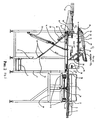
- FIG. 2 there is shown the apparatus with loading and unloading system.
- FIG. 3 there is shown chamber (view A-A).
- the chamber 1 consists of the case 13 with the folding bottom 14 and with the loading hatch 15 on the back side of the case.
- the device 16 for mechanical press of a tire rubber cover 17 is fixed on the inner side of the hatch 15.
- the manipulator 18 with pressure elements 19 for compression of tire cover and for creation of mechanical stresses in rubber is placed on the inner side of the case 13 opposite to the hatch 15.
- the manipulator 18 is fixed on the shaft 20 and has the drive 21, for example, pneumatic type.
- the shaft 20 and the pneumatic cylinder drive 21 are on one axis.
- the hatch 15 has the drive 22, and the folding bottom 14 has the drive 23.
- the drive 22 of the hatch is on the outer side of the case 13.
- the drive 23 of the folding bottom 14 is fixed on the base 2 of the apparatus.
- the system of levers creates reliable closed bottom sealing.
- Inside the case 13 is placed separating collector 24 for feeding working gas flow uniformly to a waste tire 17 surface.
- the collector 24 is connected to the branch pipe 25.
- the socket 26 and 27 for a feeding blow air into the chamber and for suction of used gas are welded into the case 13.
- Runners 28 are fixed on the inner side the folding bottom 14.
- the tire 17 before processing is placed on the runners 28.
- the chamber 1 has the safety valve 29.
- the construction of the folding bottom sealing with hatch is shown on Fig.4 .
- Gasket material 31 is attached through all perimeter of case 13 box-type trough 30. This construction allows dispose of flanges on the case, folding bottom and hatch.
- Gasket material in the box-type trough ensures the reliable and smooth sealing with minimal press force of the pneumatic cylinder.
- Construction of the chamber (view C) is shown on Fig. 5 .
- Mechanical latches 32, shown on Fig. 6 are placed on the outer sides of the hatch. Mechanical latches 32 have the pneumatic drive 33. Cylinder of the pneumatic drive is fixed on the basis 2.
- the side walls 8 and 9 of the conveyor 7 have a different height.
- the height of the front side wall 8 is 1.2-1.5 times bigger than maximum diameter of a tire for example, of passenger car.
- the height of the wall 9 is 0.5-0.6 times smaller than abovementioned tire.
- the wall 9 has the spout 34 stated in an angle to the horizontal plane from 48° to 53°. Stopping devices 35 are placed onto the spout 34 for ensuring nonimpact opening of the bottom 14.
- Platform 36 of the carriage 4 is opened from the hatch 15 side and there are borders 37 on other three sides.
- the carriage 4 during tire loading is placed on the guide rails 3 thus the surface of the platform 36 to be higher in 10-15 mm than bottom 14 surface.
- a tire 17 can be placed right onto the runners 28.
- the carriage 4 movement along chambers 1 is implemented by drive 38 for example chain-drive.
- the guide rails 3 are placed on the supporting frame 39 which is connected to the apparatus base 2.
- the offered apparatus and system for its loading and unloading operates as follows.
- a clean tire 17 is placed on the platform 36 of the carriage 4.
- the carriage 4 moves on the guide rails 3 and is set in front of one processing chambers 1 hatch 15.
- the bottom 14 is moved 10-15 mm down and opens the hatch 15.
- a tire 17 by pusher 5 is pushed onto the chambers 1 bottom 14.
- the hatch 15 is closing and the bottom 14 is pressed to the gasket material 31 creating proper hermetic of the chamber 1.
- the opening is fixing tightly by the latches 32 and providing compensation of the force influence of manipulator 18.
- the carriage 4 is moved back to the loading position and provides next tire to the following working chamber. This cambers drive 21 of the manipulator 18 is switched on.
- Manipulator 18 fixed on the shaft 20, compresses and makes mechanical stresses in the tire.
- a tire 17 is compressed by manipulator and device 16 pressure plates 19. Then rubber gets mechanical stress and appears tire form deformations.
- Three-way automatic valve Vm is opening for used gas suction and simultaneously opening the valve Voz for ozone feeding to this chamber.
- Advantages of the apparatus enable to obtain the purpose of the invention: simplifying waste tires loading system in the apparatus for waste tires processing and unloading tire covers processed by ozone. Decrease of the ozone consumption and decrease of the apparatus capacity, increasing the efficiency of the apparatus.
Landscapes
- Engineering & Computer Science (AREA)
- Environmental & Geological Engineering (AREA)
- Mechanical Engineering (AREA)
- Separation, Recovery Or Treatment Of Waste Materials Containing Plastics (AREA)
- Processing Of Solid Wastes (AREA)
- Manipulator (AREA)
Abstract
Description
- The invention relates to waste tires reprocessing. The offered apparatus, its loading and unloading system are intended for technologies of recycling vehicles waste tires. Waste tires recycling combined technologies are the most suitable for this apparatus. In this technology of tires reprocessing there is no shattering and pulverization. In combined technology the whole tire is loaded into working chamber and compressed by mechanical pressure. The tire placed in apparatus is processed by ozone-containing gas. Then remains of rubber with cord is cooled up (frozen) to rubber embrittle cryogenic temperature and separate from a cord by means of one known mechanical methods.
- The construction of the apparatus, its loading and unloading system depends of waste tire recycling technology. The most common technologies are: mechanical crushing of a tire and mechanical crushing with subsequent cryogenic temperature freezing. Other used recycling methods are processing with ozone-containing gas and method of extrusion. In known technologies, usually tires previously are crushed.
- Few constructions of the apparatus for recycling of vehicles waste tires and also tire loading and rubber crumb unloading systems are described in the patents:
- Patent
US 5 492 657 ,U.S. Cl. 264/37 ,83, 319 ;204/176, 24 - Patent
US 5 904 305 ,U.S. Cl. 241/79.1 ,157, 236, 243 ; - Patent
US 6 354 523 B1 ,U.S. CI. 241/19, 21 ,23, 172 5 ;525/237 ; - Patent
US 6 425 540 ,U.S. Cl. 241/65 ;241/235, 236 ; - Patent
US 6 579 950 B2 ,U.S. Cl. 525/388 ;241/235, 236 ;525/332 8 ;525/332 4 ; - Patent
US 6 581 861 B1 ,U.S. Cl. 241/159 ;241/DIG.31 241/DIG.38 241/65,159 - Patent
US 2004173699 , Int. CI. B29B 17/02; - Patent
EP0482723 , Int. CI.B29B 17/02; C08J 11/16; B02C 23/34; - Patent
EP1016508 , Int. CI.B29B 17/02; C08J 11/16; B02C 23/34; - Patent
RU 2191692 B29B 17/00;B02C 23/24; C08J 11/16;B29K 21/00; - Patent
RU 2265516 B29B 17/00;B29K 21/00; - Patent
LT 2005 018 B29B 17/00; B02C 23/24;B29K 21/00; - Patent
LT 2005 084 B29B 17/00; B02C 23/24;B29K 21/00; - Patent application
US 60/716 572 US Cl. 241/1 ;241/23, 245 525/332.8 ;525/332.4 ; - Various designs of the apparatus for recycling waste tires and systems of their loading are known.
- The apparatus for recycling waste tires is described in patent
US 5 492 657 ,Cl. 264/17 ,37, 83, 319 contain vertical shaft in height divided into few chambers. Chambers are separated one from another by a lock-gate. In working chamber there are placed two pairs of pinch rollers the processing tire is moving between it. Mechanical stresses are made by pinch rollers. Simultaneously, working gas (air with ozone) is fed to a tire. After processing the tire is thrown down into intermediate chamber, and then is fed into crushing machine. The loading system includes belt conveyor and collecting chamber. Described apparatus and system for its loading have following disadvantages: - there is no tire directing into clearance between rollers device in the apparatus;
- a compression of a tire between two pairs of rollers does not make uniform stresses in rubber;
- loading system comprise conveyor and collecting chamber, where the tire from the conveyor is fed into lock-gate, and it reduces the reliability of sealing between working and collecting chambers.
- The apparatus for recycling waste tires and system for its loading under the patent
LT 5368 - The loading system contains rail conveyor with moving platforms. The platforms have gripping mechanisms for a moving and a feeding it by conveyor into the chamber. On the stringer of the platform there are devices for tire fixing and creating mechanical stresses. The apparatus design and its loading system have following disadvantages:
- apparatus construction is complicated it contains three door witch complicates synchronized work and potential of platform movement into chamber and out of it.
- apparatus has a chamber with a large working volume which increases the duration of tire reprocessing and complicates blowing process by ozone-containing gas.
- loading system has complicated design consisting of the rail conveyor and mobile platform. This design requires of special devices for exact fixing of the platform with regards to force device drives.
- The apparatus for tire rubber cover destruction and system for its loading and unloading has following distinctive features.
- The apparatus consists of several chambers, each of which is fixed on its own basis. The chambers are connected by pipelines for working gas or blow air feeding and for used gas suction. The chamber case is made as the cylinder with truncated side walls. The manipulator with pressure plates and a drive, for example, pneumatic type where placed into the chamber and can make reciprocal motion.
- The chamber has the loading hatch produced as a cylinder sector. Waste tire by manipulator is pressed down to the pressure plates which are fixed on the inner side of the hatch. As a result of the pressure in a tire rubber cover are created mechanical stress. The hatch as well as manipulator, is supplied with a drive, for example, pneumatic type. Mechanical latches with pneumatic drive are placed on external sides of the hatch. It ensures hatch sealing at manipulator operation.
- The chamber has folding bottom with a drive. The tire is fed to the hatch of the working chamber by means of the carriage which is placed on the guide rails fixed along working chambers. The carriage has a pusher for tire loading into the chamber.
- Under the bottoms of the chambers there are vibrating conveyors. The bottom of the chamber can open without contact with walls of the conveyor. The conveyor side walls are protective structure of the apparatus. The height of one side wall is bigger than maximum diameter of a tire (for example, of passenger car) in 1.2 - 1.5 times, and the height of the opposite side wall is less than maximum diameter of a tire in 1.7 - 2.0 times. Smaller side wall has a spout stated in angle to horizontal plane, from 48° to 53°.
-
-
Fig. 1 is shown a schematic view of an apparatus for tire rubber cover destruction with unloading system. -
Fig. 2 is shown view of an apparatus chamber with loading and unloading system. -
Fig. 3 is shown view of a chamber case (view A - A), manipulator with pressure plates and the device for mechanical press on tire rubber cover. -
Fig. 4 is shown view of folding bottom sealing with hatch. -
Fig. 5 is shown view of chamber (view C) with pneumatic drive for hatch opening and closing. -
Fig. 6 is shown view of mechanical latches with pneumatic drive for hatch fixation and sealing. - In
Fig. 1 is shown schematic figure of the apparatus (view from back side), with system drives for running the apparatus. The apparatus consists of few working chambers 1, for example four chambers. Each chamber is fixed on itsown base 2. Along chamber 1 (Fig. 2 ) there are fixed guide rails 3 on which there is placed mobile carriage 4 for providing tires to the chamber 1. The carriage 4 has a pusher 5, for example, with a pneumatic drive 6. The pusher 5 is intended for loading a tire in the working chamber 1. The device has vibratingconveyor 7 placed under chambers 1. The belt of theconveyor 7 has about 3°-5° incline towards unloading.Side walls conveyor 7 are a protective structure of the apparatus. For supplying ozone, blow air and used gas suction in chambers 1, they were connected with each other bypipelines pipeline 10 for a supplying gas (ozone) into the chambers 1 there are placed solenoid-operated valves Voz. Onto the pipeline 11 for supplying blow air there are placed automatically operated valves Va and onto thepipeline 12 for a used gas suction there are placed thee-way automatic valves Vm. - In
Fig. 2 there is shown the apparatus with loading and unloading system. InFig. 3 there is shown chamber (view A-A). The chamber 1 consists of thecase 13 with thefolding bottom 14 and with theloading hatch 15 on the back side of the case. Thedevice 16 for mechanical press of atire rubber cover 17 is fixed on the inner side of thehatch 15. Themanipulator 18 withpressure elements 19 for compression of tire cover and for creation of mechanical stresses in rubber is placed on the inner side of thecase 13 opposite to thehatch 15. Themanipulator 18 is fixed on theshaft 20 and has thedrive 21, for example, pneumatic type. Theshaft 20 and thepneumatic cylinder drive 21 are on one axis. Thehatch 15 has thedrive 22, and thefolding bottom 14 has thedrive 23. Thedrive 22 of the hatch is on the outer side of thecase 13. Thedrive 23 of thefolding bottom 14 is fixed on thebase 2 of the apparatus. The system of levers creates reliable closed bottom sealing. Inside thecase 13 is placed separatingcollector 24 for feeding working gas flow uniformly to awaste tire 17 surface. Thecollector 24 is connected to thebranch pipe 25. Thesocket case 13.Runners 28 are fixed on the inner side thefolding bottom 14. Thetire 17 before processing is placed on therunners 28. The chamber 1 has thesafety valve 29. The construction of the folding bottom sealing with hatch is shown onFig.4 .Gasket material 31 is attached through all perimeter ofcase 13 box-type trough 30. This construction allows dispose of flanges on the case, folding bottom and hatch. Gasket material in the box-type trough ensures the reliable and smooth sealing with minimal press force of the pneumatic cylinder. Construction of the chamber (view C) is shown onFig. 5 . Mechanical latches 32, shown onFig. 6 , are placed on the outer sides of the hatch. Mechanical latches 32 have thepneumatic drive 33. Cylinder of the pneumatic drive is fixed on thebasis 2. - The
side walls conveyor 7 have a different height. The height of thefront side wall 8 is 1.2-1.5 times bigger than maximum diameter of a tire for example, of passenger car. The height of thewall 9 is 0.5-0.6 times smaller than abovementioned tire. Thewall 9 has thespout 34 stated in an angle to the horizontal plane from 48° to 53°. Stoppingdevices 35 are placed onto thespout 34 for ensuring nonimpact opening of the bottom 14. -
Platform 36 of the carriage 4 is opened from thehatch 15 side and there areborders 37 on other three sides. The carriage 4 during tire loading is placed on the guide rails 3 thus the surface of theplatform 36 to be higher in 10-15 mm than bottom 14 surface. As a result of it atire 17 can be placed right onto therunners 28. The carriage 4 movement along chambers 1 is implemented bydrive 38 for example chain-drive. The guide rails 3 are placed on the supportingframe 39 which is connected to theapparatus base 2. - The offered apparatus and system for its loading and unloading operates as follows.
- A
clean tire 17 is placed on theplatform 36 of the carriage 4. The carriage 4 moves on the guide rails 3 and is set in front of one processing chambers 1hatch 15. The bottom 14 is moved 10-15 mm down and opens thehatch 15. Atire 17 by pusher 5 is pushed onto the chambers 1 bottom 14. Then thehatch 15 is closing and the bottom 14 is pressed to thegasket material 31 creating proper hermetic of the chamber 1. When thehatch 15 is closed the opening is fixing tightly by thelatches 32 and providing compensation of the force influence ofmanipulator 18. As soon as, thehatch 15 is in the working position and chamber is hermetic the carriage 4 is moved back to the loading position and provides next tire to the following working chamber. This cambers drive 21 of themanipulator 18 is switched on.Manipulator 18 fixed on theshaft 20, compresses and makes mechanical stresses in the tire. Atire 17 is compressed by manipulator anddevice 16pressure plates 19. Then rubber gets mechanical stress and appears tire form deformations. Three-way automatic valve Vm is opening for used gas suction and simultaneously opening the valve Voz for ozone feeding to this chamber. - At the feeding of ozone to the surface of a tire rubber cover in the spots of
manipulator 18 anddevice 16 impact, results a tire partly destructs with forming a rubber crumb. A feed of ozone and accordingly, destruction of a tire rubber cover continues from 5 to 8 minutes. Duration of the processing depends on weight and sizes of the tire. During destruction by ozone themanipulator 18 makes few reciprocal motions to create various mechanical stresses. At the end of the tire processing by ozone the valve Voz is closing, and valve Va for feeding blow air to the chamber 1 is opening. The duration of blowing chamber 1 cavity takes 1.0-1.5 minutes. Then, closes the valve Va, puts down the bottom 14 to the stoppingdevices 35 and opens thehatch 15. Then the bottom 14 is lowering, pieces of a tire protector parts, rubber crumb, cord with remains of a rubber is throw down on theconveyor 7. Tire cord part thrown on theconveyor 7 on the supporting side. The remains of a tire can roll because the conveyor belt is placed with an incline. A rubber crumb is thrown into the bunker (not shown on figures), and cord with a rubber remains moves to a following technological operation of the process for example to the intensive freezing by cryogenic refrigerant. As soon as the chamber is vacated from the processed tire and a rubber crumb, a new tire is feed by a carriage 4 to the working place. The bottom 14 is lowered to set level (from 10 to 15 mm to working position). By pusher 5 the tire is passed in to the chamber, closes thehatch 15, puts the bottom into working position and repeats tire rubber cover destruction process in this chamber. - Advantages of the apparatus enable to obtain the purpose of the invention: simplifying waste tires loading system in the apparatus for waste tires processing and unloading tire covers processed by ozone. Decrease of the ozone consumption and decrease of the apparatus capacity, increasing the efficiency of the apparatus.
- 1. The apparatus consist of several working chambers. One tire can be placed and the rubber cover destruction is made by ozone in each chamber. Construction of the chamber allows processing the full tire surface evenly with decrease of ozone consumption.
- 2. The loading system enable place the tire in an axis of the chamber. This reduces the force for tire deformation and reduces strain on drive of the power mechanism.
- 3. The apparatus has vibrating conveyor on which the processed tires are fed. And there is possibility of maximal separation of tire protector parts and crumbs.
- 4. The reliable sealing of the working chamber cavity is obtainable by using box-type sealing instead flange.
Claims (9)
- The apparatus for tire rubber cover destruction and its loading and unloading system comprising working chambers, characterized in that:a) the apparatus consist of several chambers, each of which is fixed on its own basis;b) chambers are connected by pipelines for feeding working gas or blow air and for used gas suction;c) mobile carriage for tires feeding into working chamber is placed on the guide rails fixed along working chamber;d) the apparatus has vibrating conveyor with side walls which are protective structure of the apparatus;e) case of the chamber is made as cylinder with truncated side walls; it has the folding bottom and the loading hatch;f) manipulator with pressure plates is placed in the chamber and can make reciprocal motions and on the internal surface of the hatch is fixed the device with analogous pressure plates for mechanical press on tire rubber cover.
- The apparatus according to claim 1, characterized in that the chamber contains the hatch produced as a cylinder sector form.
- The apparatus according to claim 1, characterized in that the chamber contains the folding bottom with the drive fixed on the basis of chamber.
- The apparatus according to claim 1, characterized in that the height of one side wall is bigger than maximum diameter of a tire (for example, of passenger car) in 1.2 to 1.5 times, and the height of the opposite side wall is smaller than maximum diameter of a tire in 0.5 to 0.6 times.
- The apparatus according to claim 1, characterized in that smaller height wall has a spout stated in angle to horizontal plane, from 48° to 53°.
- The apparatus according to claim 1, characterized in that the carriage has the reversing drive, for example, with chain-drive.
- The apparatus according to claim 1, characterized in that the shaft of the manipulator and the pneumatic cylinder drive are placed in one axis.
- The apparatus according to claim 2, characterized in that mechanical latches with pneumatic force cylinders re placed on both sides of the hatch.
- The apparatus according to claim 1, characterized in that the chamber case has a box-type sealing in perimeter of the chamber and the bottom edge of the hatch.
Applications Claiming Priority (2)
| Application Number | Priority Date | Filing Date | Title |
|---|---|---|---|
| LT2006097A LT5522B (en) | 2006-12-27 | 2006-12-27 | Apparatus for tire rubber covering destruction and system for its loading and unloading |
| PCT/LT2007/000010 WO2008078975A1 (en) | 2006-12-27 | 2007-12-21 | Device for destroying a tire rubber envelope and a system for loading and unloading it |
Publications (3)
| Publication Number | Publication Date |
|---|---|
| EP2106894A1 true EP2106894A1 (en) | 2009-10-07 |
| EP2106894A4 EP2106894A4 (en) | 2013-01-23 |
| EP2106894B1 EP2106894B1 (en) | 2014-10-22 |
Family
ID=39562716
Family Applications (1)
| Application Number | Title | Priority Date | Filing Date |
|---|---|---|---|
| EP20070851832 Not-in-force EP2106894B1 (en) | 2006-12-27 | 2007-12-21 | Device for destroying a tire rubber envelope and a system for loading and unloading it |
Country Status (3)
| Country | Link |
|---|---|
| EP (1) | EP2106894B1 (en) |
| LT (1) | LT5522B (en) |
| WO (1) | WO2008078975A1 (en) |
Families Citing this family (1)
| Publication number | Priority date | Publication date | Assignee | Title |
|---|---|---|---|---|
| CN113694565B (en) * | 2021-09-02 | 2023-02-21 | 上海盛普流体设备股份有限公司 | Defoaming device with sectional type screw and ceramic bushing and defoaming method thereof |
Family Cites Families (20)
| Publication number | Priority date | Publication date | Assignee | Title |
|---|---|---|---|---|
| JPS4831513U (en) | 1971-08-24 | 1973-04-17 | ||
| US5253328A (en) | 1989-11-17 | 1993-10-12 | Microelectronics & Computer Technology Corp. | Neural-network content-addressable memory |
| DE4033599C3 (en) | 1990-10-23 | 1998-09-17 | Ubd Patent Lizenzverwaltung | Plant for shredding soft material, especially waste rubber |
| US5253324A (en) | 1992-09-29 | 1993-10-12 | North Carolina State University | Conical rapid thermal processing apparatus |
| US5492657A (en) | 1993-01-25 | 1996-02-20 | Danschikov; Eugene V. | Method for processing rubber products |
| RU2051035C1 (en) * | 1993-12-10 | 1995-12-27 | Фирма "Салта Инк" | Device for the recovery of worn-down casings |
| UA47425C2 (en) * | 1995-03-16 | 2002-07-15 | Євгєній Владіміровіч Даньщіков | Method for processing general mechanical-rubber goods |
| US5904305A (en) | 1997-05-14 | 1999-05-18 | Kaczmarek; Win F. | Rubber reducing and recycling system |
| EP1016508A1 (en) | 1997-09-15 | 2000-07-05 | Otkrytoe Aktsionernoe Obschestvo "Troitskaya Tekhologiskaya Laboratoriya" | Method for recycling rubber-containing articles, particularly reinforced articles such as the tire casings of vehicles, and device for realising the same |
| CZ284889B6 (en) | 1998-07-17 | 1999-03-17 | Eduard Gutfreund | Apparatus for treating industrial rubber and plastic waste |
| CZ292487B6 (en) * | 1999-03-11 | 2003-10-15 | Stanislav Kopřiva | Method for tearing waste pneumatic tyres and apparatus for making the same |
| US6425540B1 (en) | 2000-02-29 | 2002-07-30 | Charles D. Morris | Method and apparatus for grinding rubber |
| US6354523B1 (en) | 2000-04-04 | 2002-03-12 | Yangsheng Liu | Method and apparatus for recycling rubber |
| CN1151917C (en) | 2000-09-28 | 2004-06-02 | 住友橡胶工业株式会社 | Rubber waste treating apparatus and method |
| RU2191692C2 (en) | 2000-12-13 | 2002-10-27 | Красноярский государственный технический университет | Device for reprocessing rubber articles |
| US20040173699A1 (en) | 2003-03-04 | 2004-09-09 | Takao Takasaki | Tire recycling system and apparatus used therefor |
| RU2265516C1 (en) | 2004-04-05 | 2005-12-10 | Открытое акционерное общество "Механобр-Техника" | Worm grinder of worn automobile tires |
| RU39530U1 (en) * | 2004-05-21 | 2004-08-10 | Гурьянов Александр Владимирович | TECHNOLOGICAL LINE FOR PROCESSING RUBBER PRODUCTS |
| LT5368B (en) | 2005-02-24 | 2006-10-25 | Uzdaroji Akcine Bendrove "Ostrio" | Destructing device of rubber shell of worn tyre |
| LT5422B (en) | 2005-09-08 | 2007-05-25 | Uždaroji akcinė bendrovė OSTRIO | Device and method for recycling waste tires of vehicles |
-
2006
- 2006-12-27 LT LT2006097A patent/LT5522B/en not_active IP Right Cessation
-
2007
- 2007-12-21 EP EP20070851832 patent/EP2106894B1/en not_active Not-in-force
- 2007-12-21 WO PCT/LT2007/000010 patent/WO2008078975A1/en not_active Ceased
Also Published As
| Publication number | Publication date |
|---|---|
| LT2006097A (en) | 2008-07-25 |
| LT5522B (en) | 2008-10-27 |
| EP2106894B1 (en) | 2014-10-22 |
| WO2008078975A1 (en) | 2008-07-03 |
| EP2106894A4 (en) | 2013-01-23 |
Similar Documents
| Publication | Publication Date | Title |
|---|---|---|
| KR102200855B1 (en) | Apparatus for processing material, and waste container/separating device | |
| CN108057495A (en) | A kind of frivolous metal crushes and sorter and its treatment process | |
| US20120065280A1 (en) | Method, process and device for polymeric waste processing | |
| US20040206675A1 (en) | Vehicle for classifying and collecting refuse | |
| EP2106894B1 (en) | Device for destroying a tire rubber envelope and a system for loading and unloading it | |
| US4987829A (en) | Perforator/crusher for plastic bottles | |
| CN117284603B (en) | An intelligent residue-free unpacking system and its control method | |
| CN115144239B (en) | A soil sample drying and crushing device | |
| CN221852460U (en) | A high-sealing fully automatic bag opening machine | |
| JP5874065B2 (en) | Volume reduction equipment and resource recovery system for beverage containers | |
| CN109049429A (en) | A kind of waste and old wood plastic composite Special crushing recyclable device of high intensity | |
| CN103803315A (en) | Movable pebble coal device | |
| CN207823156U (en) | A kind of frivolous metal is broken and sorter | |
| SU1752562A1 (en) | Automatic line for cold crushing of warn treads reinforced with metal cord | |
| CN106115144A (en) | The shrouding system for unlocking of waste transportation | |
| SU1728042A1 (en) | Apparatus for separating and shredding rubber of automobile tyres | |
| JP2742365B2 (en) | How to dismantle a car | |
| CN111113802A (en) | Automatic feeding and discharging injection molding machine | |
| CN221209342U (en) | Automatic recovery equipment for beverage bottles and cans | |
| KR102832541B1 (en) | Apparutus for eliminating glass of waste refrigerator | |
| JPH10211442A (en) | Conveyor-type waste fluorescent tube crushing treatment storage device | |
| CN223279508U (en) | Automatic unpacking device | |
| CN214394979U (en) | Sponge package block crushing and recycling line | |
| CN219682640U (en) | Rural highway asphalt residue processing apparatus | |
| CN113617434B (en) | Old hen powder seasoning production equipment and method |
Legal Events
| Date | Code | Title | Description |
|---|---|---|---|
| PUAI | Public reference made under article 153(3) epc to a published international application that has entered the european phase |
Free format text: ORIGINAL CODE: 0009012 |
|
| 17P | Request for examination filed |
Effective date: 20090629 |
|
| AK | Designated contracting states |
Kind code of ref document: A1 Designated state(s): AT BE BG CH CY CZ DE DK EE ES FI FR GB GR HU IE IS IT LI LT LU LV MC MT NL PL PT RO SE SI SK TR |
|
| DAX | Request for extension of the european patent (deleted) | ||
| RAP1 | Party data changed (applicant data changed or rights of an application transferred) |
Owner name: UAB DEVULCO |
|
| A4 | Supplementary search report drawn up and despatched |
Effective date: 20130104 |
|
| RIC1 | Information provided on ipc code assigned before grant |
Ipc: B29B 17/02 20060101ALI20121220BHEP Ipc: B29B 17/00 20060101AFI20121220BHEP |
|
| GRAP | Despatch of communication of intention to grant a patent |
Free format text: ORIGINAL CODE: EPIDOSNIGR1 |
|
| RIC1 | Information provided on ipc code assigned before grant |
Ipc: B29B 17/00 20060101AFI20131119BHEP Ipc: B29B 17/02 20060101ALI20131119BHEP |
|
| INTG | Intention to grant announced |
Effective date: 20131209 |
|
| GRAS | Grant fee paid |
Free format text: ORIGINAL CODE: EPIDOSNIGR3 |
|
| GRAA | (expected) grant |
Free format text: ORIGINAL CODE: 0009210 |
|
| AK | Designated contracting states |
Kind code of ref document: B1 Designated state(s): AT BE BG CH CY CZ DE DK EE ES FI FR GB GR HU IE IS IT LI LT LU LV MC MT NL PL PT RO SE SI SK TR |
|
| REG | Reference to a national code |
Ref country code: GB Ref legal event code: FG4D |
|
| REG | Reference to a national code |
Ref country code: CH Ref legal event code: EP |
|
| REG | Reference to a national code |
Ref country code: AT Ref legal event code: REF Ref document number: 692394 Country of ref document: AT Kind code of ref document: T Effective date: 20141115 |
|
| REG | Reference to a national code |
Ref country code: IE Ref legal event code: FG4D |
|
| REG | Reference to a national code |
Ref country code: DE Ref legal event code: R096 Ref document number: 602007039003 Country of ref document: DE Effective date: 20141204 |
|
| REG | Reference to a national code |
Ref country code: NL Ref legal event code: VDEP Effective date: 20141022 |
|
| REG | Reference to a national code |
Ref country code: AT Ref legal event code: MK05 Ref document number: 692394 Country of ref document: AT Kind code of ref document: T Effective date: 20141022 |
|
| REG | Reference to a national code |
Ref country code: LT Ref legal event code: MG4D |
|
| PG25 | Lapsed in a contracting state [announced via postgrant information from national office to epo] |
Ref country code: NL Free format text: LAPSE BECAUSE OF FAILURE TO SUBMIT A TRANSLATION OF THE DESCRIPTION OR TO PAY THE FEE WITHIN THE PRESCRIBED TIME-LIMIT Effective date: 20141022 Ref country code: FI Free format text: LAPSE BECAUSE OF FAILURE TO SUBMIT A TRANSLATION OF THE DESCRIPTION OR TO PAY THE FEE WITHIN THE PRESCRIBED TIME-LIMIT Effective date: 20141022 Ref country code: IS Free format text: LAPSE BECAUSE OF FAILURE TO SUBMIT A TRANSLATION OF THE DESCRIPTION OR TO PAY THE FEE WITHIN THE PRESCRIBED TIME-LIMIT Effective date: 20150222 Ref country code: ES Free format text: LAPSE BECAUSE OF FAILURE TO SUBMIT A TRANSLATION OF THE DESCRIPTION OR TO PAY THE FEE WITHIN THE PRESCRIBED TIME-LIMIT Effective date: 20141022 Ref country code: LT Free format text: LAPSE BECAUSE OF FAILURE TO SUBMIT A TRANSLATION OF THE DESCRIPTION OR TO PAY THE FEE WITHIN THE PRESCRIBED TIME-LIMIT Effective date: 20141022 Ref country code: PT Free format text: LAPSE BECAUSE OF FAILURE TO SUBMIT A TRANSLATION OF THE DESCRIPTION OR TO PAY THE FEE WITHIN THE PRESCRIBED TIME-LIMIT Effective date: 20150223 |
|
| PG25 | Lapsed in a contracting state [announced via postgrant information from national office to epo] |
Ref country code: GR Free format text: LAPSE BECAUSE OF FAILURE TO SUBMIT A TRANSLATION OF THE DESCRIPTION OR TO PAY THE FEE WITHIN THE PRESCRIBED TIME-LIMIT Effective date: 20150123 Ref country code: AT Free format text: LAPSE BECAUSE OF FAILURE TO SUBMIT A TRANSLATION OF THE DESCRIPTION OR TO PAY THE FEE WITHIN THE PRESCRIBED TIME-LIMIT Effective date: 20141022 Ref country code: SE Free format text: LAPSE BECAUSE OF FAILURE TO SUBMIT A TRANSLATION OF THE DESCRIPTION OR TO PAY THE FEE WITHIN THE PRESCRIBED TIME-LIMIT Effective date: 20141022 Ref country code: LV Free format text: LAPSE BECAUSE OF FAILURE TO SUBMIT A TRANSLATION OF THE DESCRIPTION OR TO PAY THE FEE WITHIN THE PRESCRIBED TIME-LIMIT Effective date: 20141022 Ref country code: PL Free format text: LAPSE BECAUSE OF FAILURE TO SUBMIT A TRANSLATION OF THE DESCRIPTION OR TO PAY THE FEE WITHIN THE PRESCRIBED TIME-LIMIT Effective date: 20141022 Ref country code: CY Free format text: LAPSE BECAUSE OF FAILURE TO SUBMIT A TRANSLATION OF THE DESCRIPTION OR TO PAY THE FEE WITHIN THE PRESCRIBED TIME-LIMIT Effective date: 20141022 |
|
| PG25 | Lapsed in a contracting state [announced via postgrant information from national office to epo] |
Ref country code: BE Free format text: LAPSE BECAUSE OF NON-PAYMENT OF DUE FEES Effective date: 20141231 |
|
| REG | Reference to a national code |
Ref country code: DE Ref legal event code: R119 Ref document number: 602007039003 Country of ref document: DE |
|
| PG25 | Lapsed in a contracting state [announced via postgrant information from national office to epo] |
Ref country code: EE Free format text: LAPSE BECAUSE OF FAILURE TO SUBMIT A TRANSLATION OF THE DESCRIPTION OR TO PAY THE FEE WITHIN THE PRESCRIBED TIME-LIMIT Effective date: 20141022 Ref country code: SK Free format text: LAPSE BECAUSE OF FAILURE TO SUBMIT A TRANSLATION OF THE DESCRIPTION OR TO PAY THE FEE WITHIN THE PRESCRIBED TIME-LIMIT Effective date: 20141022 Ref country code: RO Free format text: LAPSE BECAUSE OF FAILURE TO SUBMIT A TRANSLATION OF THE DESCRIPTION OR TO PAY THE FEE WITHIN THE PRESCRIBED TIME-LIMIT Effective date: 20141022 Ref country code: LU Free format text: LAPSE BECAUSE OF FAILURE TO SUBMIT A TRANSLATION OF THE DESCRIPTION OR TO PAY THE FEE WITHIN THE PRESCRIBED TIME-LIMIT Effective date: 20141221 Ref country code: CZ Free format text: LAPSE BECAUSE OF FAILURE TO SUBMIT A TRANSLATION OF THE DESCRIPTION OR TO PAY THE FEE WITHIN THE PRESCRIBED TIME-LIMIT Effective date: 20141022 Ref country code: DK Free format text: LAPSE BECAUSE OF FAILURE TO SUBMIT A TRANSLATION OF THE DESCRIPTION OR TO PAY THE FEE WITHIN THE PRESCRIBED TIME-LIMIT Effective date: 20141022 |
|
| REG | Reference to a national code |
Ref country code: CH Ref legal event code: PL |
|
| PLBE | No opposition filed within time limit |
Free format text: ORIGINAL CODE: 0009261 |
|
| STAA | Information on the status of an ep patent application or granted ep patent |
Free format text: STATUS: NO OPPOSITION FILED WITHIN TIME LIMIT |
|
| PG25 | Lapsed in a contracting state [announced via postgrant information from national office to epo] |
Ref country code: IT Free format text: LAPSE BECAUSE OF FAILURE TO SUBMIT A TRANSLATION OF THE DESCRIPTION OR TO PAY THE FEE WITHIN THE PRESCRIBED TIME-LIMIT Effective date: 20141022 |
|
| GBPC | Gb: european patent ceased through non-payment of renewal fee |
Effective date: 20150122 |
|
| REG | Reference to a national code |
Ref country code: IE Ref legal event code: MM4A |
|
| REG | Reference to a national code |
Ref country code: FR Ref legal event code: ST Effective date: 20150831 |
|
| 26N | No opposition filed |
Effective date: 20150723 |
|
| PG25 | Lapsed in a contracting state [announced via postgrant information from national office to epo] |
Ref country code: CH Free format text: LAPSE BECAUSE OF NON-PAYMENT OF DUE FEES Effective date: 20141231 Ref country code: GB Free format text: LAPSE BECAUSE OF NON-PAYMENT OF DUE FEES Effective date: 20150122 Ref country code: IE Free format text: LAPSE BECAUSE OF NON-PAYMENT OF DUE FEES Effective date: 20141221 Ref country code: DE Free format text: LAPSE BECAUSE OF NON-PAYMENT OF DUE FEES Effective date: 20150701 Ref country code: LI Free format text: LAPSE BECAUSE OF NON-PAYMENT OF DUE FEES Effective date: 20141231 |
|
| PG25 | Lapsed in a contracting state [announced via postgrant information from national office to epo] |
Ref country code: FR Free format text: LAPSE BECAUSE OF NON-PAYMENT OF DUE FEES Effective date: 20141231 |
|
| PG25 | Lapsed in a contracting state [announced via postgrant information from national office to epo] |
Ref country code: SI Free format text: LAPSE BECAUSE OF FAILURE TO SUBMIT A TRANSLATION OF THE DESCRIPTION OR TO PAY THE FEE WITHIN THE PRESCRIBED TIME-LIMIT Effective date: 20141022 |
|
| PG25 | Lapsed in a contracting state [announced via postgrant information from national office to epo] |
Ref country code: BG Free format text: LAPSE BECAUSE OF FAILURE TO SUBMIT A TRANSLATION OF THE DESCRIPTION OR TO PAY THE FEE WITHIN THE PRESCRIBED TIME-LIMIT Effective date: 20141022 Ref country code: MC Free format text: LAPSE BECAUSE OF FAILURE TO SUBMIT A TRANSLATION OF THE DESCRIPTION OR TO PAY THE FEE WITHIN THE PRESCRIBED TIME-LIMIT Effective date: 20141022 |
|
| PG25 | Lapsed in a contracting state [announced via postgrant information from national office to epo] |
Ref country code: TR Free format text: LAPSE BECAUSE OF FAILURE TO SUBMIT A TRANSLATION OF THE DESCRIPTION OR TO PAY THE FEE WITHIN THE PRESCRIBED TIME-LIMIT Effective date: 20141022 Ref country code: HU Free format text: LAPSE BECAUSE OF FAILURE TO SUBMIT A TRANSLATION OF THE DESCRIPTION OR TO PAY THE FEE WITHIN THE PRESCRIBED TIME-LIMIT; INVALID AB INITIO Effective date: 20071221 Ref country code: MT Free format text: LAPSE BECAUSE OF FAILURE TO SUBMIT A TRANSLATION OF THE DESCRIPTION OR TO PAY THE FEE WITHIN THE PRESCRIBED TIME-LIMIT Effective date: 20141022 |