EP2106077B1 - Verfahren und Vorrichtung zur Funkkommunikation - Google Patents
Verfahren und Vorrichtung zur Funkkommunikation Download PDFInfo
- Publication number
- EP2106077B1 EP2106077B1 EP09165436.8A EP09165436A EP2106077B1 EP 2106077 B1 EP2106077 B1 EP 2106077B1 EP 09165436 A EP09165436 A EP 09165436A EP 2106077 B1 EP2106077 B1 EP 2106077B1
- Authority
- EP
- European Patent Office
- Prior art keywords
- slot
- data
- packet
- slots
- data packet
- Prior art date
- Legal status (The legal status is an assumption and is not a legal conclusion. Google has not performed a legal analysis and makes no representation as to the accuracy of the status listed.)
- Expired - Lifetime
Links
Images


Classifications
-
- H—ELECTRICITY
- H04—ELECTRIC COMMUNICATION TECHNIQUE
- H04W—WIRELESS COMMUNICATION NETWORKS
- H04W16/00—Network planning, e.g. coverage or traffic planning tools; Network deployment, e.g. resource partitioning or cells structures
- H04W16/02—Resource partitioning among network components, e.g. reuse partitioning
-
- H—ELECTRICITY
- H04—ELECTRIC COMMUNICATION TECHNIQUE
- H04W—WIRELESS COMMUNICATION NETWORKS
- H04W8/00—Network data management
- H04W8/18—Processing of user or subscriber data, e.g. subscribed services, user preferences or user profiles; Transfer of user or subscriber data
-
- H—ELECTRICITY
- H04—ELECTRIC COMMUNICATION TECHNIQUE
- H04W—WIRELESS COMMUNICATION NETWORKS
- H04W28/00—Network traffic management; Network resource management
- H04W28/02—Traffic management, e.g. flow control or congestion control
- H04W28/04—Error control
-
- H—ELECTRICITY
- H04—ELECTRIC COMMUNICATION TECHNIQUE
- H04W—WIRELESS COMMUNICATION NETWORKS
- H04W28/00—Network traffic management; Network resource management
- H04W28/16—Central resource management; Negotiation of resources or communication parameters, e.g. negotiating bandwidth or QoS [Quality of Service]
- H04W28/18—Negotiating wireless communication parameters
-
- H—ELECTRICITY
- H04—ELECTRIC COMMUNICATION TECHNIQUE
- H04W—WIRELESS COMMUNICATION NETWORKS
- H04W88/00—Devices specially adapted for wireless communication networks, e.g. terminals, base stations or access point devices
- H04W88/08—Access point devices
Definitions
- the present invention relates to data communication. More particularly, the present invention relates to a novel and improved method and apparatus for performing fast closed-loop rate adaptation in a high rate packet data transmission.
- an access terminal is a device providing data connectivity to a user.
- An access terminal may be coupled to a computing device, such as a desktop computer, a laptop computer, or a personal data assistant (PDA), or it may be physically incorporated into any such devices.
- An access point is equipment that provides data connectivity between a packet switched data network and access terminals.
- An example of an access terminal that can be used to provide wireless connectivity is a mobile telephone that is part of a communication system capable of supporting a variety of applications.
- One such communication system is a code division multiple access (CDMA) system which conforms to the "TIA/EIA/IS-95 Mobile Station-Base Station Compatibility Standard for Dual-Mode Wideband Spread Spectrum Cellular System", hereinafter referred to as the IS-95 standard.
- CDMA code division multiple access
- the CDMA system allows for voice and data communications between users over a terrestrial link.
- the use of CDMA techniques in a multiple access communication system is disclosed in U.S. Patent No.
- the IS-95 standard is capable of transmitting traffic data and voice data over the forward and reverse links.
- a method for transmitting traffic data in code channel frames of fixed size is described in detail in U.S. Patent No. 5,504,773 , entitled “METHOD AND APPARATUS FOR THE FORMATTING OF DATA FOR TRANSMISSION,” assigned to the assignee of the present invention.
- the traffic data or voice data is partitioned into code channel frames which are 20 msec wide with data rates as high as 14.4 Kbps.
- GOS grade of service
- data packet The GOS of a data communication system is typically defined as the total delay incurred in the transfer of a predetermined amount of data, hereinafter referred to as a data packet.
- voice services requires a reliable communication link which, in the exemplary CDMA communication system, is provided by soft handoff.
- Soft handoff results in redundant transmissions from two or more base stations to improve reliability.
- this additional reliability is not required for data transmission because the data packets received in error can be retransmitted.
- the transmit power used to support soft handoff can be more efficiently used for transmitting additional data.
- the transmission delay required to transfer a data packet and the average throughput rate of a communication system are parameters that measure the quality and effectiveness of the data communication system. Transmission delay does not have the same impact in data communication as it does for voice communication, but it is an important metric for measuring the quality of the data communication system.
- the average throughput rate is a measure of the efficiency of the data transmission capability of the communication system.
- the signal-to-interference-and-noise ratio (SINR) of any given user is a function of the location of the user within the coverage area.
- SINR signal-to-interference-and-noise ratio
- TDMA time division multiple access
- FDMA frequency division multiple access
- frequency reuse techniques i.e. not all frequency channels and/or time slots are used in each base station.
- CDMA Code Division Multiple Access
- the SINR measured at any given user's mobile station determines the information rate that can be supported for this particular link from the base station to the user's mobile station.
- an open-loop rate adaptation algorithm is used to adjust the data rate of the forward link.
- An exemplary HDR system is described in U.S. Patent Application No. 08/963,386 , entitled “METHOD AND APPARATUS FOR HIGH RATE PACKET DATA TRANSMISSION,” assigned to the assignee of the present invention.
- the open-loop rate adaptation algorithm adjusts the data rate in accordance with the varying channel conditions typically found in a wireless environment.
- an access terminal measures the received SINR during periods of pilot signal transmissions on the forward link. The access terminal uses the measured SINR information to predict the future average SINR over the next data packet duration.
- the open-loop rate adaptation method is highly dependent upon the accuracy of the SINR estimate.
- imperfect SINR measurements would prevent the access terminal from making a precise characterization of the underlying channel statistics.
- One factor that would lead to imprecise channel statistics is the feedback delay discussed above. Due to the feedback delay, the access terminal must predict a supportable data rate in the near future using past and present noisy SINR estimates.
- Another factor that would lead to imprecise channel statistics is the unpredictable, bursty nature of received data packets. In a packet data cellular system, such bursts cause sudden changes in the interference levels seen at the access terminal. The unpredictability of the interference levels cannot be efficiently accounted for by a pure open-loop rate adaptation scheme.
- Another reason for not implementing a pure open-loop rate adaptation method is an inability to minimize the effects of errors. For example, when the prediction error for an estimated SINR is large, as in the case of some mobile environments, the access terminal will transmit a conservative data rate request in order to ensure a low packet error probability. A low packet error probability will provide low overall delays in the transmission. However, it is probable that the access terminal could have successfully received a higher data rate packet. There is no mechanism in the open-loop rate adaptation method to update a data rate request based on estimated channel statistics with a data rate based on the actual channel statistics during the transmission of a data packet. Hence, the open-loop rate adaptation method would not provide a maximized throughput rate when the prediction error for an estimated SINR is large.
- RLP Radio Link Protocol
- the Radio Link Protocol requires a retransmission request when the access terminal incorrectly decodes a packet, but the retransmission request is generated only after detecting a gap in the received sequence number space. Therefore, the RLP protocol requires the processing of a subsequent received packet after the incorrectly decoded packet. This procedure increases the overall transmission delay.
- Some mechanism is needed to implement a quick retransmission of some or all of the code symbols contained in the data packet, wherein the mechanism would enable the access terminal to correctly decode the packet without incurring excessive delays.
- WO 99/22481 relates to an incremental redundancy radio link protocol. A method and apparatus for sending blocks of data without any error correcting coding is described. If a block is received without an error, then the next block of data is transmitted. If the block is received with an error, the receiving device sends a message requesting error correcting information. The transmitting device sends the error correcting information in specified increments until the receiving device can successfully decode the block without error. Once the block is received without errors, the next block of data is transmitted.
- the present invention is directed to a novel and improved method and apparatus for modifying an open-loop rate adaptation algorithm to produce a hybrid open loop/closed loop rate adaptation scheme.
- An access point advantageously generates a time interleaved structure for slots in data packets, allowing an access terminal to transmit indicator messages to the access point during periods associated with gaps inserted into the interleaved structure.
- the periods associated with the interleaved gaps are of sufficient duration to allow the access terminal to decode the data carried in the slots and to send an indicator message based on the decoded data.
- the indicator messages are based on an estimated signal-to-interference-and-noise level.
- the indicator messages are one bit long, which is interpreted by the access point in accordance with the timing of the arrival of the bit.
- forward link data transmission occurs from one access point to one or more access terminals at the data rate requested by the access terminal(s).
- Reverse link data communication can occur from one access terminal to one or more access points.
- Data is partitioned into data packets, with each data packet being transmitted over one or more time slots.
- the access point can direct data transmission to any access terminal in communication with the access point.
- the access terminal establishes communication with an access point using a predetermined access procedure.
- the access terminal can receive data messages and control messages from the access point, and is able to transmit data messages and control messages to the access point.
- the access terminal then monitors the forward link for transmissions from the access points in the active set of the access terminal.
- the active set contains a list of access points in communication with the access terminal.
- the access terminal measures the signal-to-interference-and-noise ratio (SINR) of the forward link pilot from the access points in the active set, as received at the access terminal. If the received pilot signal is above a predetermined add threshold or below a predetermined drop threshold, the access terminal reports this to the access point. Subsequent messages from the access point direct the access terminal to add or delete the access point to or from its active set, respectively.
- SINR signal-to-interference-and-noise ratio
- the access terminal If there is no data to send, the access terminal returns to an idle state and discontinues transmission of data rate information to the access point(s). While the access terminal is in the idle state, the access terminal periodically monitors the control channel from one or more access points in the active set for paging messages.
- the data is sent by a central controller to all access points in the active set and stored in a queue at each access point.
- a paging message is then sent by one or more access points to the access terminal on the respective control channels.
- the access point may transmit all such paging messages at the same time across several access points in order to ensure reception even when the access terminal is switching between access points.
- the access terminal demodulates and decodes the signals on one or more control channels to receive the paging messages.
- the access terminal Upon decoding the paging messages, and for each time slot until the data transmission is completed, the access terminal measures the SINR of the forward link signals from the access points in the active set, as received at the access terminal.
- the SINR of the forward link signals can be obtained by measuring the respective pilot signals.
- the access terminal selects the best access point based on a set of parameters.
- the set of parameters can comprise the present and previous SINR measurements and the bit-error-rate or packet-error-rate. For example, the best access point can be selected based on the largest SINR measurement.
- the access terminal then identifies the best access point and transmits to the selected access point a data rate control message (hereinafter referred to as the DRC message) on the data rate control channel (hereinafter referred to as the DRC channel).
- the DRC message can contain the requested data rate, or alternatively, the quality of the forward link channel (e.g., the SINR measurement itself, the bit-error-rate, or the packet-error-rate).
- the access terminal can direct the transmission of the DRC message to a specific access point by the use of a Walsh code that uniquely identifies the access point.
- the DRC message symbols are exclusively OR'ed (XOR) with the unique Walsh code. Since each access point in the active set of the access terminal is identified by a unique Walsh code, only the selected access point which performs the identical XOR operation as that performed by the access terminal, with the correct Walsh code, can correctly decode the DRC message.
- the access point uses the rate control information from each access terminal to efficiently transmit forward link data at the highest possible rate.
- the access point can select any of the paged access terminals for data transmission.
- the access point determines the data rate at which to transmit the data to the selected access terminal based on the most recent value of the DRC message received from the access terminal.
- the access point uniquely identifies a transmission to a particular access terminal by appending an identifying preamble to a data packet directed to an access terminal.
- the preamble is spread using a Walsh code that uniquely identifies the access terminal.
- the forward link capacity of the data transmission system is determined by the data rate requests of the access terminals. Additional gains in the forward link capacity can be achieved by using directional antennas and/or adaptive spatial filters.
- An exemplary method and apparatus for providing directional transmissions are disclosed in copending U.S. Patent Application No. 08/575,049 , entitled “METHOD AND APPARATUS FOR DETERMINING THE TRANSMISSION DATA RATE IN A MULTI-USER COMMUNICATION SYSTEM", filed December 20, 1995, and U.S. Patent Application Serial No.
- FCL Fast Closed-Loop
- an open-loop rate adaptation scheme uses a fast feedback channel to allow a transmission of a DRC message from an access terminal to an access point while the access point concurrently transmits a data packet to the access terminal on the forward data link.
- the access terminal can command the access point to either terminate or extend the current transmission in accordance with actual SINR conditions at the receiving access terminal.
- the fast feedback channel is used to carry extra information as described below.
- the forward link data rates in an HDR system vary from 38.4 kbps to 2.456 Mbps.
- the duration of each packet transmission in number of slots as well as other modulation parameters are described in Table 1.
- a slot corresponds to a period of 1.666ms, or equivalently, 2048 chips transmitted at the chip rate 1.2288 Mcps.
- Table 1 Forward Link Modulation Parameters Data Rate number Data Rate (kbps) Number of Slots Bits per Packet Code Rate Modulation 1 38.4 16 1024 1 ⁇ 4 QPSK 2 76.8 8 1024 1 ⁇ 4 QPSK 3 102.4 6 1024 1 ⁇ 4 QPSK 4 153.6 4 1024 1 ⁇ 4 QPSK 5 204.8 3 1024 1 ⁇ 4 QPSK 6 307.2 2 1024 1 ⁇ 4 QPSK 7 614.4 1 1024 1 ⁇ 4 QPSK 8 921.6 2 3072 3/8 QPSK 9 1228.8 1 2048 1 ⁇ 2 QPSK 10 1843.2 1 3072 1 ⁇ 2 8PSK 11 2457.6 1 4096 1 ⁇ 2 16QAM
- the structure of the multi-slot packets is modified to carry data in predetermined data slots, but not in predetermined gap slots.
- the access terminal that is receiving the multi-slot packet can utilize the duration of the predetermined gap slots for other purposes. For example, the access terminal can use the time between the data slots to decide if the packet can be correctly decoded with the soft code symbols accumulated thus far.
- the access terminal can use various methods for determining whether the data slots have been correctly decoded, these methods including, but not limited to, checking the CRC bits associated with the data or estimating a predicted SINR based on received SINR of pilot and traffic symbols.
- FIG. 1 is a diagram of an exemplary one-slot gap interlaced structure for multi-slot packets, wherein the predetermined data slots and the predetermined gap slots are interlaced in an alternating pattern.
- This embodiment will be referred to hereafter as a one-slot gap pattern.
- Multi-slot packet 100 is transmitted from an access point to an access terminal with data contained in alternating slots. For example, if the access terminal is transmitting in accordance with Data Rate 2 from Table 1, then there are 8 data slots in a multi-slot packet, and data would be carried in slots 1, 3, 5, 7, 9, 11, 13, and 15. Slots 2, 4, 6, 8, 10, 12,14, and 16 would not be used to transmit portions of the multi-slot packet.
- a DRC message from the access terminal can be transmitted to the access point during time periods associated with the empty slots.
- an access point can transmit another data packet to the same or different access terminal during the gap slots associated with the transmission of the 8-slot packet example.
- this embodiment permits the transmission of indicator messages from the access terminal to the access point, which indicates a reception status of the access terminal, such indicator messages including, but not limited to STOP indicator messages or EXTEND indicator messages. It should be noted that the usage of indicator messages herein described for this embodiment are applicable for other embodiments that follow.
- code symbols that are transmitted in a packet at data rates of 307.2 kbps and below are repeats of the code symbols that are transmitted in a packet at 614.4 kbps.[E1]
- most of the code symbols transmitted in a given slot are shifted repetitions of the code symbols transmitted in the first slot of the packet.
- the lower data rates require a lower SINR for a given low probability of packet error.
- the access terminal determines that channel conditions are not favorable, the access terminal will transmit a DRC message requesting a data rate below 614.4 kbps.
- the access point will then transmit multi-slot packets in accordance with the structure described in FIG. 1 .
- the structure described in FIG. 1 will allow the access terminal to transmit an indicator message, such as a STOP indicator message, on the reverse link feedback channel.
- FIG. 2 is a diagram that illustrates the use of a STOP indicator message.
- An access point transmits a data packet 200 in accordance with the interleaved structure of FIG. 1 .
- Slots n , n +2, and n +4 are slots carrying data.
- a DRC message 210 is received during slot period n -1, so that data in slots n , n +2, n +4, and n +6 are scheduled for transmission in accordance with the requested data rate.
- a STOP indicator message 220 is transmitted by the access terminal because the access terminal has received enough repetitions of the code symbols in slots n , n +2, and n +4 to determine the complete data without receiving any more repetitions carried by n +6. Hence, the access terminal is ready to receive new data.
- STOP indicator message 220 is received by the access point during slot n +5. Upon receiving the STOP indicator message 220, the access point will cease transmitting repetitions in the remaining allocated data slot n +6 and begin the transmission of a new data packet in slot n +6. Unused allocated slots can be reassigned to another packet transmission directed toward any access terminal. In this manner, a closed loop rate adaptation can be performed to optimize resources when actual channel conditions allow for a higher data rate than the one specified in the original DRC message based on estimated channel conditions. In the example above, an effective data rate 4/3 times higher than the original requested data rate is achieved by sending the STOP indication.
- an indicator message can be sent from the access terminal to the access point to enable more repetitions of the code symbols whenever the actual channel conditions are worse than the estimated channel conditions.
- the indicator message can be referred to as an EXTEND indicator message.
- Another use for an EXTEND indicator message arises when a one slot packet is incorrectly decoded by the access terminal.
- the access terminal may transmit an EXTEND indicator message requesting the retransmission of the data carried in a specified slot.
- the structure of FIG. 1 allows the access point to retransmit the data on the very next slot, referred to herein as an extended data slot, following the decoding of the EXTEND indicator message.
- FIG. 3 is an illustration of this use for an EXTEND indicator message.
- Data packet 300 is constructed in accordance with the structure of FIG. 1 , so that alternating slots are designated gap slots.
- a DRC message 310 is received by the access point that provides the preferred rate for data transmitted in data slot n .
- Data is also transmitted in slot n +2 in accordance with the requested data rate.
- an EXTEND indicator message 320 is received by the access point that orders data repetition at data slot n +4 due to an error in decoding the data carried in slot n +2.
- single-slot packets may be requested when the estimated SINR indicates a reduced probability of packet success, for example, a probability of packet success of 80-90%.
- the access terminal can send an EXTEND indicator to the access point, requesting retransmission of the packet, if the first single-slot packet has not been decoded correctly.
- This aspect of the embodiment has the advantage of an improved data throughput rate, which is achieved by the initial transmission of a high data rate.
- the high data rate transmission can be adjusted according to actual channel conditions.
- FIG. 3 also illustrates this aspect of the invention.
- the DRC message 310 carries a data request of 307.2 kbps, then data is transmitted in slots n and n +2 at the requested rate. However, if the access terminal detects an improvement in the channel conditions, the access terminal can send a DRC message 330 carrying a data request of 1.2 Mbps. The access point will then transmit a single-slot packet at 1.2 Mbps in slot n +5. During the time associated with the gap slot n +6, the access terminal detects a deterioration in the channel conditions, which necessitates the retransmission of the data in slot n +5 . A EXTEND message 340 is transmitted and the access point retransmits the data from slot n +5 in slot n +7.
- the procedure described above for a closed loop rate adaptation is exemplary in transmissions where the data packet comprises one or two slots.
- the extended data slot carries code symbols that are repetitions of previously transmitted code symbols, and therefore, the code symbols in the extended data slots may be advantageously soft-combined with the previously received code symbols prior to the decoding step in order to improve reliability.
- the identification of which code symbols are to be transmitted in an extended data slot is an implementation detail and does not effect the scope of this invention.
- the fast closed loop rate adaptation method described above can be implemented to rely on the same fast feedback channel used by the open loop rate adaptation scheme, but it should be noted that another separate channel may also be used to implement the closed loop rate adaptation method without altering the scope of the invention.
- Another aspect of implementation is the formulation of the indicator messages.
- the system needs only use one bit to carry the indicator message.
- DRC messages carry multiple bits for rate selection and access point identification, but only one bit is needed to indicate a STOP indicator message or an EXTEND indicator message if the system discriminates the context of the bit upon usage.
- an indicator bit may be designated as a FCL bit. If the access point detects the presence of the FCL bit from an access terminal in slot n , then the access point will interpret the FCL bit as a STOP indicator message if a data slot of a multi-slot packet directed to this access terminal is scheduled for transmission in slot n +1.
- the access point will interpret the FCL bit as an EXTEND indicator message if a packet scheduled to this access terminal and according to a requested data rate ended exactly in slot n -1.
- the access point can also interpret the FCL bit as an EXTEND indicator message if a previous EXTEND indicator message caused the retransmission of a slot of a specified packet exactly in slot n -1 and less than N EXT EXTEND indicator messages have been processed for this packet. If none of these situations are applicable, then the bit can be discarded as a false alarm.
- the indicator messages can be transmitted on the same feedback channel reserved for the open loop DRC messages by using one of the reserved DRC codewords.
- the access terminal cannot simultaneously transmit a DRC message and an indicator message such as a STOP indicator message because only one message can be transmitted at a time.
- the access terminal will be prevented from being served another packet during the first slot released after the STOP indication was sent.
- other access terminals may be served in the first slot release. The efficiency of this embodiment is then maximized if the access point serves many access terminals since the probability that packets for a given access terminal would be contiguously scheduled is reduced.
- the indicator messages can be transmitted on a separate assigned channel, which can be created using extra Walsh functions on the reverse link.
- This approach has the extra advantage of allowing the access terminal to control the reliability of the FCL channel to a desirable level.
- the access point can maximize efficiency by transmitting data to other access terminals during the gap slots.
- FIG. 4 is a diagram of an exemplary interlaced structure for multi-slot packets, wherein the predetermined data slots and the predetermined gap slots are interlaced in a uniform N -slot pattern.
- This embodiment will be referred to hereafter as the uniform N -slot gap pattern.
- Multi-slot packet 400 is transmitted from an access point to an access terminal with the data contained in every N th slot.
- N- 1 slots are gap slots, wherein the access terminal may use the delay associated with the gap slots to attempt decoding the data received in the previous data slot.
- blocks of data bits may be transmitted with coding to enable the recipient of the data to determine the existence of any errors in the data transmission.
- the delay caused by the uniform insertion of gaps enables the access terminal to decode CRC bits and to determine if the data slot was successfully decoded. Rather than sending indicator messages based on SINR estimation, the access terminal may send indicator messages based on the actual success or failure of decoding a data slot.
- the time needed to decode data is usually proportional to the number of information bits contained in the packet. Thus, as seen in Table 1, the higher data rate packets require more time for decoding. When determining an optimal value for N , the worst case delay must be taken into account when selecting the interlacing period.
- the delay caused by the uniform insertion of gaps enables the access terminal to determine the estimated SINR during the reception of the data slots and transmit a DRC message advantageously.
- extra slots of delay can be inserted in the multi-slot packet to enable the access terminal to transmit additional messages to the access point.
- STOP indicator messages and EXTEND indicator messages can be used in the uniform N -slot gap pattern.
- the formulation of the indicator messages can be accomplished using only one bit, if the system discriminates the context of the bit upon usage. For example, an indicator bit may be designated as a FCL bit. If the access point detects the presence of the FCL bit from an access terminal in slot n , then the access point will interpret the FCL bit as a STOP indicator message if a data slot of a multi-slot packet directed to this access terminal is scheduled for transmission in slot n +1.
- the access point will interpret the FCL bit as an EXTEND indicator message if a packet scheduled to this access terminal, according to a requested data rate, ended exactly in slot n - p +1, wherein p is the period of the assigned data slots to an access terminal.
- the access point can also interpret the FCL bit as an EXTEND indicator message if a previous EXTEND indicator message caused the retransmission of a slot of a specified packet exactly in slot n - p +1, and less than N EXT EXTEND indicator messages have been processed for this packet. If none of these situations are applicable, then the bit can be discarded as a false alarm.
- FIG. 5 is a diagram of another exemplary interlaced structure for multi-slot packets, wherein the predetermined data slots and the predetermined gap slots are interlaced in a non-uniform slot pattern.
- This embodiment of the invention will be referred to hereafter as the non-uniform N-slot gap pattern.
- Multi-slot packet 500 is structured so that delays interlaced between data slots are a function of the data rate.
- the number of gap slots required between data slots of a packet at rate i is fixed and known by all access terminals and access point.
- this embodiment allows for the latency of each data rate packet to be minimized, there are a certain number of constraints that the access point must satisfy when scheduling the packets for transmission.
- One such constraint is the prevention of overlapping data slots.
- the DRC messages of FIG. 5 can be used to transmit data in staggered patterns.
- DRC message 510 requests that data transmitted in slots n -2, n +2, and n +6 be transmitted at 204.8 kbps.
- DRC message 520 requests that data is transmitted in slots n +1 and n +3 at 921.6 kbps.
- DRC message 530 requests that data is transmitted in slot n +8 at 1.2 Mbps.
- the individual DRC messages are for periodic transmissions, the periodic transmissions are combined to create an aperiodic, non-uniform pattern. It should be noted that there is a constraint as to the data pattern initiated by DRC message 520.
- a two-slot data packet with a one slot gap in between the pair of data slots could have been scheduled to begin transmission at n +1 or n -1, but not at n . If the pattern had begun at n , then the current slot n +3 data would have been transmitted at slot n +2, which would have overlapped the data slot pattern scheduled with DRC message 510.
- STOP indicator messages and EXTEND indicator messages can be used in the non-uniform N -slot gap pattern.
- the formulation of the indicator messages can be accomplished using only one bit, if the system discriminates the context of the bit upon usage. For example, an indicator bit may be designated as a FCL bit. If the access point detects the presence of the FCL bit from an access terminal in slot n , then the access point will interpret the FCL bit as a STOP indicator message if a data slot of a multi-slot packet directed to this access terminal is scheduled for transmission in slot n + 1 .
- the access point will interpret the FCL bit as an EXTEND indicator message if a packet scheduled to this access terminal, according to a requested data rate, ended exactly in slot n - N(i) , wherein N(i) is the number of gap slots required between data slots and i indicates a data rate index number.
- the access point can also interpret the FCL bit as an EXTEND indicator message if a previous EXTEND indicator message caused the retransmission of a slot of a specified packet exactly in slot n - N(i) and less than N EXT EXTEND indicator messages have been processed for this packet. If none of these situations are applicable, then the bit can be discarded as a false alarm.
- a system using the uniform slot gap pattern could achieve maximum slot efficiency by staggering periodic patterns across all slots. For example, in a uniform pattern wherein slots n , n + 4 , n + 8 , ... are assigned to one access terminal, a second access terminal can be assigned slots n+ 1 , n+ 5 , n + 9, ..., a third access terminal can be assigned slots n +2, n + 6, n +10, ..., and a fourth access terminal can be assigned slots n +3, n +7, n +11, .... In this manner, all slots are fully utilized to increase the efficiency of the network.
- non-uniform slot gap pattern it may be more desirable to implement a non-uniform slot gap pattern. For example, during high speed data transmissions, only one slot of data is transmitted with large amounts of code symbols. In such cases, the access terminal would require a relatively long duration to decode the received code symbols. Hence, the implementation of a uniform slot pattern would require correspondingly large periods with large amounts of gap slots, which would not be efficient. Under this circumstance, a non-uniform gap slot pattern may be preferable.
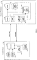
- FIG. 6 is a block diagram of an apparatus for performing FCL rate control in an HDR system.
- Access terminal 701 performs SINR estimation and prediction at SINR estimation element 722 based on the strength of the received forward link signal from access point 700.
- the results from SINR estimation element 722 are sent to open loop rate control element 723, which implements the open loop rate control algorithm in order to select a data rate in accordance with the results from SINR estimation element 722.
- the open loop rate control element 723 generates a DRC message to be sent over the reverse link to the access point 700.
- the DRC message is decoded at the DRC decoder 713 and the results are sent to the scheduler 712 so that the access point 700 can schedule data transmission at the specified requested rate in the slot following the decoding of the DRC message.
- the FCL rate control process is implemented by the scheduler 712 with the generation of interlaced packets as described above and the closed loop rate control element 725, which optionally allows the access terminal 701 to implement an FCL rate adaptation.
- a one-slot gap pattern is implemented by scheduler 712 to serve two access terminals simultaneously.
- the access point 700 maintains two independent buffers, transmit buffer A 710 and transmit buffer B 711, in order to maintain the code symbols needed to generate a new slot repetition or slot extension. It should be noted that more transmit buffers may be utilized in accordance with the embodiments described herein.
- Access point 700 transmits a data packet to access terminal 701. While receiving the data packet, the access terminal 701 may feed the results from the SINR estimation element 722 to the closed loop rate control element 725 or alternatively, the access terminal 701 may feed the results from the decoder 720 to the closed loop rate control element 725. Buffer 721 may be inserted to aid in the ordered delivery of decoded information from the decoder 720 to the upper layer protocols, which will not be described herein.
- the closed loop rate control element 725 can use results from either the decoder 720 or the SINR estimation element 722 to determine whether to generate an indication message.
- the indication message is transmitted on the reverse link to the access point 700, wherein an FCL indicator decoder 714 decodes the indicator message and feeds the decoded indicator message to the scheduler 712.
- the scheduler 712, DRC decoder 713, and the FCL indicator decoder 714 at access point 700 can be implemented as separate components or can be implemented using a single processor and memory.
- the decoder 720, buffer 721, SINR estimation element 722, open loop rate control element 723, and the closed loop rate control element 725 at the access terminal 701 can be implemented as separate elements or can be combined on a single processor with memory.
- Outer loop rate control element 724 may be inserted to compute long term error statistics. The results of such statistical computations can be used to determine a set of parameters that can be used adjust both the open loop rate control element 723 and the closed loop rate control element 725.
- the FCL rate adaptation method may decide to send an indicator message, such as a STOP indicator message or an EXTEND indicator message, to an access point.
- This method provides a fast correction mechanism to compensate for inaccuracies of the open loop rate control scheme.
- a multi-slot packet transmission can be stopped when there is sufficient information to decode the packet.
- a slot of an on-going multi-slot packet transmission can be repeated when successful decoding is not guaranteed.
- the FCL rate adaptation method also improves the throughput rate by allowing the open loop rate control scheme to be aggressive in requesting one-slot packets at higher rates, since the FCL rate adaptation method allows for the transmission of an extended slot of data if a high rate packet cannot be decoded successfully. Throughput is also improved when the FCL rate adaptation method stops a multi-slot packet earlier than expected by the open loop rate control algorithm.
- an open loop rate control scheme can be designed so that the open loop rate control selects high rates using one-slot packets with a packet error rate (PER) of approximately 15% after the end of the first slot and a PER of at most 1% at the end of the extended slot.
- PER packet error rate
- An extended slot would add at least 3 dB of average SINR in addition to any time diversity gain and puncturing loss reduction.
- the open loop rate control algorithm can target a PER of 1% at the normal end of the packet. Hence, there would be a large probability of packet success with a reduced number of slots, which corresponds to a higher than expected rate.
- an extended slot would provide an extra margin for successful decoding if necessary, thus reducing the requirement of a delayed retransmission.
- SINR values for optimal efficiency will vary according to the various modulation techniques implemented in the network, so that the possible implementation of various SINR values as threshold values are not intended to limit the scope of the embodiments described herein.
- the decision on whether to generate a STOP, EXTEND, or no FCL indication based upon SINR calculations should not be very aggressive, otherwise the probability of packet errors would be dominated by the probability that the closed loop rate control algorithm will erroneously assume that a packet can be correctly decoded.
Claims (13)
- Verfahren zur drahtlosen Kommunikation, umfassend:Empfangen einer Indikatornachricht (220, 320) basierend auf dem Erfolg oder Misserfolg einer Dekodierung eines aktuellen Datenschlitzes (n-2) eines Mehrschlitz-Datenpakets; undBeenden der Übertragung der verbleibenden Schlitze (n+2, n+6) des Mehrschlitz-Datenpakets, wenn die Dekodierung des aktuellen Datenschlitzes erfolgreich ist;dadurch gekennzeichnet, dassvorbestimmte Datenschlitze und vorbestimmte Lückenschlitze in einem einheitlichen N-Schlitzmuster in dem Mehrschlitz-Datenpaket verschachtelt sind, undaktuelle Daten, die in dem aktuellen Datenschlitz enthalten sind, für eine Vielzahl von erneuten Übertragungen geplant sind, so dass jeder N-te nachfolgende Schlitz des Mehrschlitz-Datenpakets (400) als ein Datenschlitz geplant ist, der eine erneute Übertragung der aktuellen Daten enthält.
- Verfahren nach Anspruch 1, wobei das Beenden Übertragen einer Stoppanzeige-Nachricht (220) umfasst.
- Verfahren nach Anspruch 1, ferner umfassend das Bestimmen vollständiger Daten des Mehrschlitz-Datenpakets (400) basierend auf den dekodierten Codesymbolen des aktuellen Datenschlitzes des Mehrschlitz-Datenpakets.
- Verfahren nach Anspruch 1, ferner umfassend:vor dem Empfangen des aktuellen Datenschlitzes des Mehrschlitz-Datenpakets, Anfordern (DRC) einer Datenrate zum Senden des Mehrschlitz-Datenpakets, undwobei das Mehrschlitz-Datenpaket zum Übertragen gemäß der gewünschten Datenrate geplant ist.
- Verfahren nach Anspruch 1, ferner umfassend:
nach dem Beenden der Übertragung von verbleibenden Datenschlitzen des Mehrschlitz-Datenpakets (400), Empfangen von Daten eines neuen Mehrschlitz-Datenpakets in den verbleibenden Datenschlitzen. - Verfahren nach Anspruch 1, umfassend, nach dem Beenden der Übertragung der verbleibenden Datenschlitze des Mehrschlitz-Datenpakets (400), Neuzuordnen der verbleibenden Schlitze zu einer anderen Paketübertragung zu einem anderen Empfänger.
- Verfahren nach Anspruch 1, wobei, wenn die Dekodierung nicht erfolgreich ist, das Verfahren ferner umfasst:Empfangen eines nächsten Datenschlitzes (n+2) des Mehrschlitz-Datenpakets (400);Kombinieren von Codesymbolen des aktuellen Datenschlitzes und Codesymbolen des empfangenen nächsten Datenschlitzes des Mehrschlitz-Datenpakets zu einer Kombination;Dekodieren der Kombination; undBeenden der Übertragung der verbleibenden Datenschlitze (n+6) des Mehrschlitz-Datenpakets, wenn die Dekodierung der Kombination vollständige Daten ergibt.
- Verfahren nach Anspruch 7, wobei das Beenden Übertragen einer Stoppanzeige-Nachricht (220) umfasst.
- Verfahren nach einem der Ansprüche 1-8, ferner umfassend:
Bestimmen einer erfolgreichen Dekodierung (720) durch Prüfen eines zyklischen Redundanzcodes. - Verfahren nach Anspruch 7, ferner umfassend:periodisches Übertragen von Datenraten-Steuerinformationen (DRC),wobei das Beenden der Übertragung ferner das Übertragen einer Steuernachricht mit geschlossenem Regelkreis, closed loop rate control message, umfasst.
- Verfahren zur drahtlosen Kommunikation, umfassend:Dekodieren eines aktuellen Datenschlitzes (n-2) eines Mehrschlitz-Datenpakets; undÜbertragen einer Indikatornachricht (220, 320) basierend auf dem Erfolg oder Misserfolg der Dekodierung des aktuellen Datenschlitzes, dadurch gekennzeichnet, dass:vorbestimmte Datenschlitze und vorbestimmte Lückenschlitze in einem einheitlichen N-Schlitzmuster im Mehrschlitz-Datenpaket verschachtelt sind, undaktuelle Daten, die in dem aktuellen Datenschlitz enthalten sind, für eine Vielzahl von erneuten Übertragungen geplant sind, so dass jeder N-te nachfolgende Schlitz des Mehrschlitz-Datenpakets (400) als ein Datenschlitz geplant ist, der eine erneute Übertragung der aktuellen Daten enthält.
- Vorrichtung zur drahtlosen Kommunikation, umfassend:Mittel zum Empfangen einer Indikatornachricht (220, 320) basierend auf dem Erfolg oder Misserfolg der Dekodierung eines aktuellen Datenschlitzes (n-2) eines Mehrschlitz-Datenpakets; undMittel zum Beenden der Übertragung der verbleibenden Datenschlitze (n+2, n+6) des Mehrschlitz-Datenpakets, wenn die Dekodierung des aktuellen Datenschlitzes erfolgreich ist, dadurch gekennzeichnet, dass:vorbestimmte Datenschlitze und vorbestimmte Lückenschlitze in einem einheitlichen N-Schlitzmuster im Mehrschlitz-Datenpaket verschachtelt sind, undaktuelle Daten, die in dem aktuellen Datenschlitz enthalten sind, für eine Vielzahl von erneuten Übertragungen geplant sind, so dass jeder N-te nachfolgende Schlitz des Mehrschlitz-Datenpakets (400) als ein Datenschlitz geplant ist, der eine erneute Übertragung der aktuellen Daten enthält.
- Vorrichtung zur drahtlosen Kommunikation, umfassend:Mittel zum Dekodieren eines aktuellen Datenschlitzes (n-2) eines Mehrschlitz-Datenpakets; undMittel zum Übertragen einer Indikatornachricht (220, 320) basierend auf dem Erfolg oder Misserfolg der Dekodierung des aktuellen Datenschlitzes; dadurch gekennzeichnet, dassvorbestimmte Datenschlitze und vorbestimmte Lückenschlitze in einem einheitlichen N-Schlitzmuster im Mehrschlitz-Datenpaket verschachtelt sind, undaktuelle Daten, die in dem aktuellen Datenschlitz enthalten sind, für eine Vielzahl von erneuten Übertragungen geplant sind, so dass jeder N-te nachfolgende Schlitz des Mehrschlitz-Datenpakets (400) als ein Datenschlitz geplant ist, der eine erneute Übertragung der aktuellen Daten enthält.
Applications Claiming Priority (4)
| Application Number | Priority Date | Filing Date | Title |
|---|---|---|---|
| US09/570,210 US7245594B1 (en) | 2000-05-12 | 2000-05-12 | Method and apparatus for fast closed-loop rate adaptation in a high rate packet data transmission |
| EP01937333A EP1287649B1 (de) | 2000-05-12 | 2001-05-11 | Verfahren und vorrichtung zur ratenanpassung in paketdatenübertragung |
| PCT/US2001/015381 WO2001089162A2 (en) | 2000-05-12 | 2001-05-11 | Method and apparatus for rate adaption in packet data transmission |
| EP06122876A EP1755293B1 (de) | 2000-05-12 | 2001-05-11 | Verfahren und Vorrichtung zur Ratenanpassung bei Paketdatenübertragung |
Related Parent Applications (2)
| Application Number | Title | Priority Date | Filing Date |
|---|---|---|---|
| EP01937333A Division EP1287649B1 (de) | 2000-05-12 | 2001-05-11 | Verfahren und vorrichtung zur ratenanpassung in paketdatenübertragung |
| EP06122876A Division EP1755293B1 (de) | 2000-05-12 | 2001-05-11 | Verfahren und Vorrichtung zur Ratenanpassung bei Paketdatenübertragung |
Publications (2)
| Publication Number | Publication Date |
|---|---|
| EP2106077A1 EP2106077A1 (de) | 2009-09-30 |
| EP2106077B1 true EP2106077B1 (de) | 2019-06-19 |
Family
ID=24278709
Family Applications (7)
| Application Number | Title | Priority Date | Filing Date |
|---|---|---|---|
| EP06025215A Expired - Lifetime EP1770924B1 (de) | 2000-05-12 | 2001-05-11 | Verfahren und Vorrichtung zur Funkkommunikation |
| EP09165436.8A Expired - Lifetime EP2106077B1 (de) | 2000-05-12 | 2001-05-11 | Verfahren und Vorrichtung zur Funkkommunikation |
| EP10174195A Expired - Lifetime EP2249521B1 (de) | 2000-05-12 | 2001-05-11 | Verfahren und Vorrichtung zur Ratenanpassung bei Paketdatenübertragung |
| EP01937333A Expired - Lifetime EP1287649B1 (de) | 2000-05-12 | 2001-05-11 | Verfahren und vorrichtung zur ratenanpassung in paketdatenübertragung |
| EP06122876A Expired - Lifetime EP1755293B1 (de) | 2000-05-12 | 2001-05-11 | Verfahren und Vorrichtung zur Ratenanpassung bei Paketdatenübertragung |
| EP10174185A Expired - Lifetime EP2256997B1 (de) | 2000-05-12 | 2001-05-11 | Verfahren und Vorrichtung zur Ratenanpassung bei Paketdatenübertragung |
| EP10174191A Expired - Lifetime EP2256998B1 (de) | 2000-05-12 | 2001-05-11 | Verfahren und Vorrichtung zur Ratenanpassung bei Paketdatenübertragung |
Family Applications Before (1)
| Application Number | Title | Priority Date | Filing Date |
|---|---|---|---|
| EP06025215A Expired - Lifetime EP1770924B1 (de) | 2000-05-12 | 2001-05-11 | Verfahren und Vorrichtung zur Funkkommunikation |
Family Applications After (5)
| Application Number | Title | Priority Date | Filing Date |
|---|---|---|---|
| EP10174195A Expired - Lifetime EP2249521B1 (de) | 2000-05-12 | 2001-05-11 | Verfahren und Vorrichtung zur Ratenanpassung bei Paketdatenübertragung |
| EP01937333A Expired - Lifetime EP1287649B1 (de) | 2000-05-12 | 2001-05-11 | Verfahren und vorrichtung zur ratenanpassung in paketdatenübertragung |
| EP06122876A Expired - Lifetime EP1755293B1 (de) | 2000-05-12 | 2001-05-11 | Verfahren und Vorrichtung zur Ratenanpassung bei Paketdatenübertragung |
| EP10174185A Expired - Lifetime EP2256997B1 (de) | 2000-05-12 | 2001-05-11 | Verfahren und Vorrichtung zur Ratenanpassung bei Paketdatenübertragung |
| EP10174191A Expired - Lifetime EP2256998B1 (de) | 2000-05-12 | 2001-05-11 | Verfahren und Vorrichtung zur Ratenanpassung bei Paketdatenübertragung |
Country Status (21)
| Country | Link |
|---|---|
| US (4) | US7245594B1 (de) |
| EP (7) | EP1770924B1 (de) |
| JP (3) | JP4689931B2 (de) |
| KR (2) | KR100861279B1 (de) |
| CN (2) | CN1305272C (de) |
| AT (2) | ATE553572T1 (de) |
| AU (2) | AU6308101A (de) |
| BR (1) | BRPI0110730B1 (de) |
| CA (1) | CA2408619C (de) |
| DE (2) | DE60139282D1 (de) |
| DK (4) | DK1770924T3 (de) |
| ES (7) | ES2396196T3 (de) |
| HK (6) | HK1076951A1 (de) |
| IL (4) | IL152712A0 (de) |
| MX (1) | MXPA02011181A (de) |
| NO (1) | NO327847B1 (de) |
| PT (4) | PT2256998E (de) |
| RU (1) | RU2275748C2 (de) |
| TW (1) | TWI232660B (de) |
| UA (2) | UA79923C2 (de) |
| WO (1) | WO2001089162A2 (de) |
Families Citing this family (42)
| Publication number | Priority date | Publication date | Assignee | Title |
|---|---|---|---|---|
| US7245594B1 (en) * | 2000-05-12 | 2007-07-17 | Qualcomm Incorporated | Method and apparatus for fast closed-loop rate adaptation in a high rate packet data transmission |
| US7126927B2 (en) * | 2001-11-27 | 2006-10-24 | Telefonaktiebolaget Lm Ericsson (Publ) | System and method for fair, channel-dependent scheduling for wireless systems |
| JP3989298B2 (ja) * | 2002-05-22 | 2007-10-10 | 株式会社エヌ・ティ・ティ・ドコモ | ランダムアクセス方法、無線局及びcdmaパケット通信システム |
| KR100483977B1 (ko) * | 2002-10-10 | 2005-04-19 | 엘지전자 주식회사 | 고속 패킷 데이터 방식 단문 메시지 서비스 시스템 및 방법 |
| CN1706158B (zh) * | 2002-10-17 | 2013-09-04 | 皇家飞利浦电子股份有限公司 | 调度系统及其方法 |
| JP4195009B2 (ja) * | 2002-11-26 | 2008-12-10 | クゥアルコム・インコーポレイテッド | Umtsシステムにおけるプリアンブル検出及びデータレート制御 |
| US7611480B2 (en) | 2003-04-24 | 2009-11-03 | Levy Mark M | Gastrointestinal bioreactor |
| US8488457B2 (en) * | 2003-11-14 | 2013-07-16 | Interdigital Technology Corporation | Wireless communication method and apparatus for transferring buffered enhanced uplink data from a mobile station to a node-B |
| US8040834B2 (en) * | 2004-03-31 | 2011-10-18 | Interdigital Technology Corporation | Wireless communication method and apparatus for reporting traffic volume measurement information to support enhanced uplink data transmissions |
| US7979072B2 (en) * | 2004-06-04 | 2011-07-12 | Nortel Networks Limited | Method and system for soft handoff in mobile broadband systems |
| DE102004028703A1 (de) * | 2004-06-14 | 2005-12-29 | Siemens Ag | Verfahren zur Zuweisung von Übertragungskapazitäten bei einer Signalübertragung, Basisstation und mobiles Endgerät |
| WO2006019263A2 (en) * | 2004-08-17 | 2006-02-23 | Lg Electronics Inc. | A method for establishing fast feedback channel and transmitting information in a wireless communication system |
| US20060039344A1 (en) * | 2004-08-20 | 2006-02-23 | Lucent Technologies, Inc. | Multiplexing scheme for unicast and broadcast/multicast traffic |
| US7292856B2 (en) | 2004-12-22 | 2007-11-06 | Qualcomm Incorporated | Methods and apparatus for flexible forward-link and reverse-link handoffs |
| KR100909531B1 (ko) | 2004-12-31 | 2009-07-27 | 삼성전자주식회사 | 멀티캐리어를 사용하는 통신 시스템에서 스케쥴링 장치 및방법 |
| US9240834B2 (en) * | 2005-03-22 | 2016-01-19 | Hughes Network Systems, Llc | Method and apparatus for providing open loop bandwidth allocation |
| US8254360B2 (en) * | 2005-06-16 | 2012-08-28 | Qualcomm Incorporated | OFDMA control channel interlacing |
| US7983674B2 (en) | 2005-06-16 | 2011-07-19 | Qualcomm Incorporated | Serving base station selection in a wireless communication system |
| US8125961B2 (en) | 2005-10-25 | 2012-02-28 | Qualcomm Incorporated | Four way handshake for robust channel estimation and rate prediction |
| RU2402877C1 (ru) * | 2006-08-18 | 2010-10-27 | Самсунг Электроникс Ко., Лтд. | Способ и устройство для отчета о степени приема потоковой услуги терминалом в системе мобильного вещания и система на их основе |
| KR101328798B1 (ko) * | 2007-06-11 | 2013-11-13 | 삼성전자주식회사 | 무선 통신 시스템의 셀 제어 메시지 수신 장치 및 방법 |
| KR101433939B1 (ko) * | 2007-09-13 | 2014-08-26 | 삼성전자주식회사 | 가시광 통신을 이용한 무선 랜 시스템에서 데이터 재전송방법 및 장치 |
| WO2009044367A2 (en) * | 2007-10-02 | 2009-04-09 | Nokia Siemens Networks Oy | Improved ack/nack dtx detection |
| JP2009094612A (ja) * | 2007-10-04 | 2009-04-30 | Hitachi Communication Technologies Ltd | 無線通信システムにおけるハンドオフ制御方法 |
| KR100913099B1 (ko) | 2008-01-07 | 2009-08-21 | 엘지전자 주식회사 | 분산형 가상자원블록 스케쥴링 방법 |
| RU2488219C2 (ru) * | 2008-01-07 | 2013-07-20 | Эл Джи Электроникс Инк. | Способ планирования распределенных блоков виртуальных ресурсов |
| KR100925441B1 (ko) | 2008-01-07 | 2009-11-06 | 엘지전자 주식회사 | 분산형 가상자원블록 스케쥴링 방법 |
| CN101227739B (zh) * | 2008-02-02 | 2011-12-07 | 中兴通讯股份有限公司 | 一种物理混合重传指示信道资源的分配方法 |
| CN101547433B (zh) * | 2008-03-25 | 2013-02-13 | 华为技术有限公司 | 上报终端能力信息的方法、时隙资源分配方法、装置及系统 |
| CN101562496B (zh) * | 2008-04-15 | 2012-06-06 | 中兴通讯股份有限公司 | 一种控制信道速率动态调整的系统及方法 |
| ES2394391T3 (es) * | 2008-09-11 | 2013-01-31 | Telefonaktiebolaget L M Ericsson (Publ) | Selección de modo de transmisión |
| US8516101B2 (en) * | 2009-06-15 | 2013-08-20 | Qualcomm Incorporated | Resource management for a wireless device |
| EP2302828A1 (de) * | 2009-09-29 | 2011-03-30 | Thomson Licensing | WLAN-Übertragungsgeschwindigkeitsanpassungsverfahren |
| US9712206B2 (en) * | 2010-12-27 | 2017-07-18 | Microchip Technology Incorporated | Preamble design and processing method for on-the-fly, frame-by-frame air data rate detection in wireless receivers |
| US8792407B2 (en) * | 2012-02-21 | 2014-07-29 | Qualcomm Incorporated | Wireless communication device power reduction method and apparatus |
| US8797911B2 (en) | 2012-02-21 | 2014-08-05 | Qualcomm Incorporated | Method and apparatus for reducing power consumption in a wireless communication device |
| US9668191B2 (en) * | 2012-06-11 | 2017-05-30 | Qualcomm Incorporated | Methods and apparatuses for saving user equipment power by search length reduction |
| US9078266B2 (en) | 2012-10-11 | 2015-07-07 | Qualcomm Incorporated | Devices and methods for facilitating discontinuous transmission on access terminals |
| US9161308B2 (en) | 2013-08-26 | 2015-10-13 | Qualcomm Incorporated | Devices and methods for facilitating autonomous discontinuous transmission in access terminals |
| US11070995B2 (en) | 2019-06-14 | 2021-07-20 | Cypress Semiconductor Corporation | Method for IoT device to stagger TX and save power |
| CN114287145A (zh) * | 2019-07-03 | 2022-04-05 | 诺基亚通信公司 | 在多载波动态频谱共享下的基于强化学习的无线电接入技术间负载平衡 |
| CN111585701B (zh) * | 2020-05-09 | 2023-02-24 | 哈尔滨海能达科技有限公司 | 数据传输方法、设备、系统及存储介质 |
Family Cites Families (79)
| Publication number | Priority date | Publication date | Assignee | Title |
|---|---|---|---|---|
| US3644678A (en) * | 1969-03-21 | 1972-02-22 | Communications Satellite Corp | Channel reallocation system and method |
| EP0054077B1 (de) * | 1980-12-08 | 1984-11-21 | International Business Machines Corporation | Verfahren zur Übertragung von Information zwischen Stationen, die an eine unidirektionale Ringleitung angeschlossen sind |
| US4868866A (en) | 1984-12-28 | 1989-09-19 | Mcgraw-Hill Inc. | Broadcast data distribution system |
| US4742512A (en) * | 1985-07-19 | 1988-05-03 | Nec Corporation | Multipoint communication system having polling and reservation schemes |
| US4901307A (en) | 1986-10-17 | 1990-02-13 | Qualcomm, Inc. | Spread spectrum multiple access communication system using satellite or terrestrial repeaters |
| US5227775A (en) * | 1988-05-09 | 1993-07-13 | Motorola Inc. | Method and arrangement for channel monitor and control |
| US5483676A (en) * | 1988-08-04 | 1996-01-09 | Norand Corporation | Mobile radio data communication system and method |
| US5172375A (en) * | 1989-06-22 | 1992-12-15 | Nec Corporation | Multiple access satellite communication system for mini-earth station networks |
| FI86352C (fi) * | 1989-11-14 | 1992-08-10 | Nokia Oy Ab | Digitaliskt radiolaenksystem och foerfarande foer reglering av en saendingseffekt i ett digitaliskt radiolaenksystem. |
| JP2719619B2 (ja) * | 1989-11-28 | 1998-02-25 | 日本電信電話株式会社 | 移動通信チャネル割当て制御方法 |
| US5038399A (en) * | 1990-05-21 | 1991-08-06 | Motorola, Inc. | Method for assigning channel reuse levels in a multi-level cellular system |
| US5511073A (en) | 1990-06-25 | 1996-04-23 | Qualcomm Incorporated | Method and apparatus for the formatting of data for transmission |
| US5103459B1 (en) | 1990-06-25 | 1999-07-06 | Qualcomm Inc | System and method for generating signal waveforms in a cdma cellular telephone system |
| AU665521B2 (en) * | 1990-10-03 | 1996-01-11 | Thinking Machines Corporation | Parallel computer system |
| GB9024684D0 (en) * | 1990-11-13 | 1991-01-02 | Cognito Group Ltd | A method of communicating data |
| US5295140A (en) * | 1991-03-28 | 1994-03-15 | Motorola, Inc. | Method for multi-purpose utilization of resources in a communication system |
| JP2730338B2 (ja) * | 1991-07-15 | 1998-03-25 | 日本電気株式会社 | 衛星通信方式 |
| US5287544A (en) * | 1991-10-17 | 1994-02-15 | Motorola, Inc. | Method of channel assignment by matching channel interference with channel link loss |
| US5603081A (en) | 1993-11-01 | 1997-02-11 | Telefonaktiebolaget Lm Ericsson | Method for communicating in a wireless communication system |
| US5396516A (en) * | 1993-02-22 | 1995-03-07 | Qualcomm Incorporated | Method and system for the dynamic modification of control paremeters in a transmitter power control system |
| US6005856A (en) * | 1993-11-01 | 1999-12-21 | Omnipoint Corporation | Communication protocol for spread spectrum wireless communication system |
| NZ276006A (en) * | 1993-11-01 | 1997-11-24 | Ericsson Telefon Ab L M | Cellular radio: scanning of neighbouring control channels |
| US5802105A (en) | 1994-11-30 | 1998-09-01 | Qualcomm Incorporated | Method and apparatus for testing a digital communication channel |
| GB2301992B (en) * | 1995-06-07 | 1999-07-21 | Nippon Telegraph & Telephone | Method and system for data communication |
| ATE221710T1 (de) * | 1995-10-23 | 2002-08-15 | Nokia Corp | Verfahren zur paketdatenübertragung mit hybridem fec/arq-type-ii-verfahren |
| US5790533A (en) * | 1995-10-27 | 1998-08-04 | Motorola, Inc. | Method and apparatus for adaptive RF power control of cable access units |
| US5982747A (en) * | 1995-12-28 | 1999-11-09 | Dynarc Inc. | Method for managing failures on dynamic synchronous transfer mode dual ring topologies |
| WO1997025827A1 (de) | 1996-01-04 | 1997-07-17 | Siemens Aktiengesellschaft | Verfahren und anordnung zum übertragen von daten in einem zellularen funksystem |
| CN1111986C (zh) * | 1996-04-12 | 2003-06-18 | Ntt移动通信网株式会社 | 测量接收的信噪比的方法、设备及传输功率控制系统 |
| US5929779A (en) * | 1996-05-31 | 1999-07-27 | Lucent Technologies Inc. | Read/write protocol for radio frequency identification tags |
| DE19636744C2 (de) * | 1996-09-10 | 1998-09-17 | Siemens Ag | Verfahren zum Übertragen von Daten in einem hybriden Telekommunikationssystem, insbesondere einem "ISDN - DECT-spezifischen RLL/WLL"-System |
| US5982761A (en) * | 1996-09-30 | 1999-11-09 | Amsc Subsidiary Corporation | Methods of communicating over time-division multiple-access (TDMA) communication systems with distinct non-time-critical and time-critical network management information transmission rates |
| US5933462A (en) * | 1996-11-06 | 1999-08-03 | Qualcomm Incorporated | Soft decision output decoder for decoding convolutionally encoded codewords |
| US5991286A (en) | 1997-02-20 | 1999-11-23 | Telefonaktiebolaget L M Ericsson (Publ) | Support of multiple modulation levels for a cellular packet control channel |
| ATE304755T1 (de) | 1997-05-02 | 2005-09-15 | Siemens Ag | Tdma/cdma nachrichtenübertragungssystem mit anpassbarer datenrate |
| US6154450A (en) * | 1997-08-22 | 2000-11-28 | Telefonaktiebolaget Lm Ericsson | Signaling method for CDMA quality based power control |
| US6181704B1 (en) * | 1997-08-29 | 2001-01-30 | Intel Corporation | Method and apparatus for input/output link retry, failure and recovery in a computer network |
| US6343067B1 (en) * | 1997-08-29 | 2002-01-29 | Intel Corporation | Method and apparatus for failure and recovery in a computer network |
| US6760307B2 (en) * | 1997-08-29 | 2004-07-06 | Intel Corporation | Method and apparatus for controlling the flow of data between servers using optimistic transmitter |
| US6683850B1 (en) * | 1997-08-29 | 2004-01-27 | Intel Corporation | Method and apparatus for controlling the flow of data between servers |
| US6324165B1 (en) * | 1997-09-05 | 2001-11-27 | Nec Usa, Inc. | Large capacity, multiclass core ATM switch architecture |
| US6285655B1 (en) * | 1997-09-08 | 2001-09-04 | Qualcomm Inc. | Method and apparatus for providing orthogonal spot beams, sectors, and picocells |
| US6088337A (en) * | 1997-10-20 | 2000-07-11 | Motorola, Inc. | Method access point device and peripheral for providing space diversity in a time division duplex wireless system |
| US6353907B1 (en) * | 1997-10-29 | 2002-03-05 | At&T Corp. | Incremental redundancy radio link protocol |
| US6574211B2 (en) * | 1997-11-03 | 2003-06-03 | Qualcomm Incorporated | Method and apparatus for high rate packet data transmission |
| US6192029B1 (en) * | 1998-01-29 | 2001-02-20 | Motorola, Inc. | Method and apparatus for performing flow control in a wireless communications system |
| US6778558B2 (en) * | 1998-02-23 | 2004-08-17 | Lucent Technologies Inc. | System and method for incremental redundancy transmission in a communication system |
| US6400701B2 (en) * | 1998-03-31 | 2002-06-04 | Nortel Networks Limited | Asymmetric internet access over fixed wireless access |
| FR2778055B1 (fr) * | 1998-04-28 | 2000-05-26 | Alsthom Cge Alcatel | Procede de transmission dans un reseau radiotelephonique umts,permettant de preparer un saut vers une cellule gsm pendant une communication dans une cellule umts |
| US6529730B1 (en) | 1998-05-15 | 2003-03-04 | Conexant Systems, Inc | System and method for adaptive multi-rate (AMR) vocoder rate adaption |
| US6233074B1 (en) | 1998-05-18 | 2001-05-15 | 3Com Corporation | Ring networks utilizing wave division multiplexing |
| US6219528B1 (en) * | 1998-06-29 | 2001-04-17 | Hughes Electronics Corporation | Dynamic power control with adaptive reference level |
| JP4037965B2 (ja) * | 1998-08-18 | 2008-01-23 | 富士通株式会社 | 符号分割多元接続通信システム並びに符号分割多元接続通信システム用基地局及び符号分割多元接続通信システム用端末装置並びに符号分割多元接続通信方法並びに端末装置の通信方法 |
| US20010056560A1 (en) * | 1998-10-08 | 2001-12-27 | Farooq Khan | Method and system for measurement based automatic retransmission request in a radiocommunication system |
| US6704898B1 (en) * | 1998-10-23 | 2004-03-09 | Telefonaktiebolaget Lm Ericsson (Publ) | Combined hybrid automatic retransmission request scheme |
| KR100687119B1 (ko) * | 1998-10-23 | 2007-02-27 | 텔레호낙티에볼라게트 엘엠 에릭슨(피유비엘) | 결합된 하이브리드 자동 재전송 요구 스킴 |
| US6608821B1 (en) * | 1998-11-20 | 2003-08-19 | Texas Instruments Israel Ltd. | Method for collision avoidance in an asynchronous communication system |
| US6487181B1 (en) * | 1998-11-30 | 2002-11-26 | Motorola, Inc. | Method and apparatus for transmitting and receiving information in a time slot |
| US6661774B1 (en) * | 1999-02-16 | 2003-12-09 | Efficient Networks, Inc. | System and method for traffic shaping packet-based signals |
| US6975611B1 (en) * | 1999-03-03 | 2005-12-13 | Lucent Technologies Inc. | Method and device for MAC layer feedback in a packet communication system |
| SE514361C2 (sv) | 1999-06-04 | 2001-02-12 | Ericsson Telefon Ab L M | Metod och anordning i mobilt paketdatanät |
| US6459901B1 (en) * | 1999-07-01 | 2002-10-01 | At&T Corp. | Wireless network resource allocation |
| US6426971B1 (en) * | 1999-09-13 | 2002-07-30 | Qualcomm Incorporated | System and method for accurately predicting signal to interference and noise ratio to improve communications system performance |
| US6501785B1 (en) * | 1999-11-17 | 2002-12-31 | At&T Corp. | Dynamic frequency hopping |
| US6275488B1 (en) * | 1999-11-17 | 2001-08-14 | Motorola, Inc. | Variable rate spread spectrum communication method and apparatus |
| US6687227B1 (en) * | 2000-03-13 | 2004-02-03 | Nortel Networks Limited | Systems and methods for requesting packets for transmission over a wirless channel having a dynamically changing capacity due to a highly varibale delay |
| US6603797B1 (en) * | 2000-03-22 | 2003-08-05 | Interdigital Technology Corporation | Outer loop/weighted open loop power control in a time division duplex communication system |
| US7088701B1 (en) * | 2000-04-14 | 2006-08-08 | Qualcomm, Inc. | Method and apparatus for adaptive transmission control in a high data rate communication system |
| US6751199B1 (en) * | 2000-04-24 | 2004-06-15 | Qualcomm Incorporated | Method and apparatus for a rate control in a high data rate communication system |
| US7245594B1 (en) * | 2000-05-12 | 2007-07-17 | Qualcomm Incorporated | Method and apparatus for fast closed-loop rate adaptation in a high rate packet data transmission |
| US20050203673A1 (en) * | 2000-08-18 | 2005-09-15 | Hassanayn Machlab El-Hajj | Wireless communication framework |
| US7051268B1 (en) * | 2000-09-29 | 2006-05-23 | Qualcomm Incorporated | Method and apparatus for reducing power consumption of a decoder in a communication system |
| JP4309129B2 (ja) * | 2000-10-24 | 2009-08-05 | ノーテル・ネットワークス・リミテッド | 共用チャネル構造、arqシステム及び方法 |
| US7024216B2 (en) * | 2001-06-21 | 2006-04-04 | Motorola, Inc. | Method and apparatus for allocating a communication resource in a broadband communication system |
| US7596090B2 (en) * | 2001-10-04 | 2009-09-29 | Qualcomm Incorporated | Capacity-efficient flow control mechanism |
| US6901395B2 (en) * | 2001-11-05 | 2005-05-31 | Qualcomm Incorporated | Method and apparatus for preferred roaming list compression |
| US7152289B2 (en) * | 2002-09-25 | 2006-12-26 | Intel Corporation | Method for forming bulk resonators silicon <110> substrate |
| US8248938B2 (en) * | 2004-11-24 | 2012-08-21 | Qualcomm Incorporated | Preamble miss detection in transmission of multi-slot packets |
| US9015019B1 (en) * | 2006-11-08 | 2015-04-21 | Nextel Communications Inc. | Radio access network simulator |
-
2000
- 2000-05-12 US US09/570,210 patent/US7245594B1/en not_active Expired - Lifetime
-
2001
- 2001-05-11 DK DK06025215.2T patent/DK1770924T3/da active
- 2001-05-11 ES ES10174185T patent/ES2396196T3/es not_active Expired - Lifetime
- 2001-05-11 PT PT10174191T patent/PT2256998E/pt unknown
- 2001-05-11 EP EP06025215A patent/EP1770924B1/de not_active Expired - Lifetime
- 2001-05-11 ES ES09165436T patent/ES2745951T3/es not_active Expired - Lifetime
- 2001-05-11 KR KR1020027015114A patent/KR100861279B1/ko active IP Right Grant
- 2001-05-11 AU AU6308101A patent/AU6308101A/xx active Pending
- 2001-05-11 ES ES01937333T patent/ES2362266T3/es not_active Expired - Lifetime
- 2001-05-11 EP EP09165436.8A patent/EP2106077B1/de not_active Expired - Lifetime
- 2001-05-11 DE DE60139282T patent/DE60139282D1/de not_active Expired - Lifetime
- 2001-05-11 IL IL15271201A patent/IL152712A0/xx active IP Right Grant
- 2001-05-11 DK DK10174185.8T patent/DK2256997T3/da active
- 2001-05-11 DK DK10174191.6T patent/DK2256998T3/da active
- 2001-05-11 WO PCT/US2001/015381 patent/WO2001089162A2/en active Application Filing
- 2001-05-11 TW TW090111291A patent/TWI232660B/zh not_active IP Right Cessation
- 2001-05-11 AU AU2001263081A patent/AU2001263081B8/en not_active Expired
- 2001-05-11 ES ES06025215T patent/ES2386033T3/es not_active Expired - Lifetime
- 2001-05-11 CN CNB018120601A patent/CN1305272C/zh not_active Expired - Lifetime
- 2001-05-11 BR BRPI0110730A patent/BRPI0110730B1/pt active IP Right Grant
- 2001-05-11 CN CN200610144585XA patent/CN1976315B/zh not_active Expired - Lifetime
- 2001-05-11 AT AT06025215T patent/ATE553572T1/de active
- 2001-05-11 JP JP2001585463A patent/JP4689931B2/ja not_active Expired - Lifetime
- 2001-05-11 EP EP10174195A patent/EP2249521B1/de not_active Expired - Lifetime
- 2001-05-11 EP EP01937333A patent/EP1287649B1/de not_active Expired - Lifetime
- 2001-05-11 PT PT10174185T patent/PT2256997E/pt unknown
- 2001-05-11 CA CA2408619A patent/CA2408619C/en not_active Expired - Lifetime
- 2001-05-11 EP EP06122876A patent/EP1755293B1/de not_active Expired - Lifetime
- 2001-05-11 PT PT06025215T patent/PT1770924E/pt unknown
- 2001-05-11 EP EP10174185A patent/EP2256997B1/de not_active Expired - Lifetime
- 2001-05-11 ES ES06122876T patent/ES2330034T3/es not_active Expired - Lifetime
- 2001-05-11 PT PT10174195T patent/PT2249521E/pt unknown
- 2001-05-11 KR KR1020087004677A patent/KR100925126B1/ko active IP Right Grant
- 2001-05-11 ES ES10174195T patent/ES2397545T3/es not_active Expired - Lifetime
- 2001-05-11 ES ES10174191T patent/ES2397543T3/es not_active Expired - Lifetime
- 2001-05-11 EP EP10174191A patent/EP2256998B1/de not_active Expired - Lifetime
- 2001-05-11 DE DE60144560T patent/DE60144560D1/de not_active Expired - Lifetime
- 2001-05-11 RU RU2002133468/09A patent/RU2275748C2/ru active
- 2001-05-11 AT AT01937333T patent/ATE508561T1/de not_active IP Right Cessation
- 2001-05-11 DK DK10174195.7T patent/DK2249521T3/da active
- 2001-05-11 MX MXPA02011181A patent/MXPA02011181A/es active IP Right Grant
- 2001-11-05 UA UA2002118951A patent/UA79923C2/uk unknown
-
2002
- 2002-11-07 IL IL152712A patent/IL152712A/en unknown
- 2002-11-11 NO NO20025386A patent/NO327847B1/no not_active IP Right Cessation
-
2005
- 2005-09-30 HK HK05108701A patent/HK1076951A1/xx unknown
-
2006
- 2006-11-02 JP JP2006298468A patent/JP4814053B2/ja not_active Expired - Lifetime
- 2006-11-03 US US11/592,568 patent/US8498308B2/en not_active Expired - Fee Related
- 2006-12-26 IL IL180344A patent/IL180344A/en active IP Right Grant
-
2007
- 2007-02-06 UA UAA200701257A patent/UA91684C2/ru unknown
- 2007-07-16 US US11/778,585 patent/US20070263655A1/en not_active Abandoned
- 2007-07-18 HK HK07107767.9A patent/HK1105724A1/xx unknown
- 2007-08-28 HK HK07109395.5A patent/HK1104400A1/xx unknown
-
2010
- 2010-04-28 IL IL205411A patent/IL205411A/en active IP Right Grant
- 2010-09-14 JP JP2010205267A patent/JP4778106B2/ja not_active Expired - Lifetime
-
2011
- 2011-05-04 HK HK11104438.9A patent/HK1150407A1/xx unknown
- 2011-06-01 HK HK11105512.5A patent/HK1151401A1/xx unknown
- 2011-06-01 HK HK11105514.3A patent/HK1151647A1/xx unknown
-
2013
- 2013-07-29 US US13/953,070 patent/US20130315143A1/en not_active Abandoned
Non-Patent Citations (1)
| Title |
|---|
| None * |
Also Published As
Similar Documents
| Publication | Publication Date | Title |
|---|---|---|
| EP2106077B1 (de) | Verfahren und Vorrichtung zur Funkkommunikation | |
| AU2001263081A1 (en) | Method and apparatus for fast closed-loop rate adaptation in a high rate packet data transmission | |
| US8189540B2 (en) | Method and apparatus for high rate packet data transmission | |
| EP2094042A1 (de) | Verfahren und Anordnung zur Hochgeschwindigkeitsübertragung von Datenpaketen |
Legal Events
| Date | Code | Title | Description |
|---|---|---|---|
| PUAI | Public reference made under article 153(3) epc to a published international application that has entered the european phase |
Free format text: ORIGINAL CODE: 0009012 |
|
| 17P | Request for examination filed |
Effective date: 20090714 |
|
| AC | Divisional application: reference to earlier application |
Ref document number: 1755293 Country of ref document: EP Kind code of ref document: P Ref document number: 1287649 Country of ref document: EP Kind code of ref document: P |
|
| AK | Designated contracting states |
Kind code of ref document: A1 Designated state(s): AT BE CH CY DE DK ES FI FR GB GR IE IT LI LU MC NL PT SE TR |
|
| RIN1 | Information on inventor provided before grant (corrected) |
Inventor name: ESTEVES, EDUARDO A.S. Inventor name: ATTAR, RASHID A. Inventor name: SINDHUSHAYANA, NAGABHUSHANA T. |
|
| RIN1 | Information on inventor provided before grant (corrected) |
Inventor name: SINDHUSHAYANA, NAGABHUSHANA T. Inventor name: ESTEVES, EDUARDO A.S. Inventor name: ATTAR, RASHID A. |
|
| 17Q | First examination report despatched |
Effective date: 20100226 |
|
| REG | Reference to a national code |
Ref country code: HK Ref legal event code: DE Ref document number: 1135255 Country of ref document: HK |
|
| STAA | Information on the status of an ep patent application or granted ep patent |
Free format text: STATUS: EXAMINATION IS IN PROGRESS |
|
| REG | Reference to a national code |
Ref country code: DE Ref legal event code: R079 Ref document number: 60151130 Country of ref document: DE Free format text: PREVIOUS MAIN CLASS: H04L0012560000 Ipc: H04W0028180000 |
|
| GRAJ | Information related to disapproval of communication of intention to grant by the applicant or resumption of examination proceedings by the epo deleted |
Free format text: ORIGINAL CODE: EPIDOSDIGR1 |
|
| GRAP | Despatch of communication of intention to grant a patent |
Free format text: ORIGINAL CODE: EPIDOSNIGR1 |
|
| GRAP | Despatch of communication of intention to grant a patent |
Free format text: ORIGINAL CODE: EPIDOSNIGR1 |
|
| RIC1 | Information provided on ipc code assigned before grant |
Ipc: H04W 28/18 20090101AFI20181105BHEP |
|
| STAA | Information on the status of an ep patent application or granted ep patent |
Free format text: STATUS: GRANT OF PATENT IS INTENDED |
|
| INTG | Intention to grant announced |
Effective date: 20181213 |
|
| GRAS | Grant fee paid |
Free format text: ORIGINAL CODE: EPIDOSNIGR3 |
|
| GRAA | (expected) grant |
Free format text: ORIGINAL CODE: 0009210 |
|
| STAA | Information on the status of an ep patent application or granted ep patent |
Free format text: STATUS: THE PATENT HAS BEEN GRANTED |
|
| AC | Divisional application: reference to earlier application |
Ref document number: 1287649 Country of ref document: EP Kind code of ref document: P Ref document number: 1755293 Country of ref document: EP Kind code of ref document: P |
|
| AK | Designated contracting states |
Kind code of ref document: B1 Designated state(s): AT BE CH CY DE DK ES FI FR GB GR IE IT LI LU MC NL PT SE TR |
|
| REG | Reference to a national code |
Ref country code: GB Ref legal event code: FG4D |
|
| REG | Reference to a national code |
Ref country code: CH Ref legal event code: EP |
|
| REG | Reference to a national code |
Ref country code: IE Ref legal event code: FG4D |
|
| REG | Reference to a national code |
Ref country code: DE Ref legal event code: R096 Ref document number: 60151130 Country of ref document: DE |
|
| REG | Reference to a national code |
Ref country code: AT Ref legal event code: REF Ref document number: 1147096 Country of ref document: AT Kind code of ref document: T Effective date: 20190715 |
|
| REG | Reference to a national code |
Ref country code: NL Ref legal event code: FP |
|
| PG25 | Lapsed in a contracting state [announced via postgrant information from national office to epo] |
Ref country code: SE Free format text: LAPSE BECAUSE OF FAILURE TO SUBMIT A TRANSLATION OF THE DESCRIPTION OR TO PAY THE FEE WITHIN THE PRESCRIBED TIME-LIMIT Effective date: 20190619 |
|
| PG25 | Lapsed in a contracting state [announced via postgrant information from national office to epo] |
Ref country code: GR Free format text: LAPSE BECAUSE OF FAILURE TO SUBMIT A TRANSLATION OF THE DESCRIPTION OR TO PAY THE FEE WITHIN THE PRESCRIBED TIME-LIMIT Effective date: 20190920 |
|
| REG | Reference to a national code |
Ref country code: AT Ref legal event code: MK05 Ref document number: 1147096 Country of ref document: AT Kind code of ref document: T Effective date: 20190619 |
|
| PG25 | Lapsed in a contracting state [announced via postgrant information from national office to epo] |
Ref country code: PT Free format text: LAPSE BECAUSE OF FAILURE TO SUBMIT A TRANSLATION OF THE DESCRIPTION OR TO PAY THE FEE WITHIN THE PRESCRIBED TIME-LIMIT Effective date: 20191021 Ref country code: AT Free format text: LAPSE BECAUSE OF FAILURE TO SUBMIT A TRANSLATION OF THE DESCRIPTION OR TO PAY THE FEE WITHIN THE PRESCRIBED TIME-LIMIT Effective date: 20190619 |
|
| REG | Reference to a national code |
Ref country code: ES Ref legal event code: FG2A Ref document number: 2745951 Country of ref document: ES Kind code of ref document: T3 Effective date: 20200304 |
|
| PG25 | Lapsed in a contracting state [announced via postgrant information from national office to epo] |
Ref country code: TR Free format text: LAPSE BECAUSE OF FAILURE TO SUBMIT A TRANSLATION OF THE DESCRIPTION OR TO PAY THE FEE WITHIN THE PRESCRIBED TIME-LIMIT Effective date: 20190619 |
|
| PG25 | Lapsed in a contracting state [announced via postgrant information from national office to epo] |
Ref country code: DK Free format text: LAPSE BECAUSE OF FAILURE TO SUBMIT A TRANSLATION OF THE DESCRIPTION OR TO PAY THE FEE WITHIN THE PRESCRIBED TIME-LIMIT Effective date: 20190619 |
|
| REG | Reference to a national code |
Ref country code: DE Ref legal event code: R097 Ref document number: 60151130 Country of ref document: DE |
|
| PLBE | No opposition filed within time limit |
Free format text: ORIGINAL CODE: 0009261 |
|
| STAA | Information on the status of an ep patent application or granted ep patent |
Free format text: STATUS: NO OPPOSITION FILED WITHIN TIME LIMIT |
|
| PGFP | Annual fee paid to national office [announced via postgrant information from national office to epo] |
Ref country code: FI Payment date: 20200428 Year of fee payment: 20 Ref country code: FR Payment date: 20200421 Year of fee payment: 20 Ref country code: NL Payment date: 20200421 Year of fee payment: 20 Ref country code: DE Payment date: 20200417 Year of fee payment: 20 Ref country code: ES Payment date: 20200602 Year of fee payment: 20 |
|
| 26N | No opposition filed |
Effective date: 20200603 |
|
| PGFP | Annual fee paid to national office [announced via postgrant information from national office to epo] |
Ref country code: IT Payment date: 20200521 Year of fee payment: 20 Ref country code: GB Payment date: 20200429 Year of fee payment: 20 |
|
| PG25 | Lapsed in a contracting state [announced via postgrant information from national office to epo] |
Ref country code: CH Free format text: LAPSE BECAUSE OF NON-PAYMENT OF DUE FEES Effective date: 20200531 Ref country code: LI Free format text: LAPSE BECAUSE OF NON-PAYMENT OF DUE FEES Effective date: 20200531 Ref country code: MC Free format text: LAPSE BECAUSE OF FAILURE TO SUBMIT A TRANSLATION OF THE DESCRIPTION OR TO PAY THE FEE WITHIN THE PRESCRIBED TIME-LIMIT Effective date: 20190619 |
|
| REG | Reference to a national code |
Ref country code: BE Ref legal event code: MM Effective date: 20200531 |
|
| PG25 | Lapsed in a contracting state [announced via postgrant information from national office to epo] |
Ref country code: LU Free format text: LAPSE BECAUSE OF NON-PAYMENT OF DUE FEES Effective date: 20200511 |
|
| PG25 | Lapsed in a contracting state [announced via postgrant information from national office to epo] |
Ref country code: IE Free format text: LAPSE BECAUSE OF NON-PAYMENT OF DUE FEES Effective date: 20200511 |
|
| REG | Reference to a national code |
Ref country code: DE Ref legal event code: R071 Ref document number: 60151130 Country of ref document: DE |
|
| PG25 | Lapsed in a contracting state [announced via postgrant information from national office to epo] |
Ref country code: BE Free format text: LAPSE BECAUSE OF NON-PAYMENT OF DUE FEES Effective date: 20200531 |
|
| REG | Reference to a national code |
Ref country code: GB Ref legal event code: PE20 Expiry date: 20210510 |
|
| REG | Reference to a national code |
Ref country code: FI Ref legal event code: MAE |
|
| REG | Reference to a national code |
Ref country code: NL Ref legal event code: MK Effective date: 20210510 |
|
| PG25 | Lapsed in a contracting state [announced via postgrant information from national office to epo] |
Ref country code: GB Free format text: LAPSE BECAUSE OF EXPIRATION OF PROTECTION Effective date: 20210510 |
|
| REG | Reference to a national code |
Ref country code: ES Ref legal event code: FD2A Effective date: 20210902 |
|
| PG25 | Lapsed in a contracting state [announced via postgrant information from national office to epo] |
Ref country code: ES Free format text: LAPSE BECAUSE OF EXPIRATION OF PROTECTION Effective date: 20210512 |
|
| PG25 | Lapsed in a contracting state [announced via postgrant information from national office to epo] |
Ref country code: CY Free format text: LAPSE BECAUSE OF FAILURE TO SUBMIT A TRANSLATION OF THE DESCRIPTION OR TO PAY THE FEE WITHIN THE PRESCRIBED TIME-LIMIT Effective date: 20190619 |