EP2105947A2 - Kompakt-Leuchtstofflampe und Beleuchtungsvorrichtung - Google Patents
Kompakt-Leuchtstofflampe und Beleuchtungsvorrichtung Download PDFInfo
- Publication number
- EP2105947A2 EP2105947A2 EP09250518A EP09250518A EP2105947A2 EP 2105947 A2 EP2105947 A2 EP 2105947A2 EP 09250518 A EP09250518 A EP 09250518A EP 09250518 A EP09250518 A EP 09250518A EP 2105947 A2 EP2105947 A2 EP 2105947A2
- Authority
- EP
- European Patent Office
- Prior art keywords
- globe
- light
- self
- fluorescent lamp
- emitting tube
- Prior art date
- Legal status (The legal status is an assumption and is not a legal conclusion. Google has not performed a legal analysis and makes no representation as to the accuracy of the status listed.)
- Granted
Links
Images






Classifications
-
- H—ELECTRICITY
- H01—ELECTRIC ELEMENTS
- H01J—ELECTRIC DISCHARGE TUBES OR DISCHARGE LAMPS
- H01J61/00—Gas-discharge or vapour-discharge lamps
- H01J61/02—Details
- H01J61/30—Vessels; Containers
- H01J61/32—Special longitudinal shape, e.g. for advertising purposes
- H01J61/327—"Compact"-lamps, i.e. lamps having a folded discharge path
-
- H—ELECTRICITY
- H01—ELECTRIC ELEMENTS
- H01J—ELECTRIC DISCHARGE TUBES OR DISCHARGE LAMPS
- H01J61/00—Gas-discharge or vapour-discharge lamps
- H01J61/02—Details
- H01J61/30—Vessels; Containers
- H01J61/34—Double-wall vessels or containers
-
- H—ELECTRICITY
- H01—ELECTRIC ELEMENTS
- H01J—ELECTRIC DISCHARGE TUBES OR DISCHARGE LAMPS
- H01J61/00—Gas-discharge or vapour-discharge lamps
- H01J61/02—Details
- H01J61/30—Vessels; Containers
- H01J61/35—Vessels; Containers provided with coatings on the walls thereof; Selection of materials for the coatings
-
- H—ELECTRICITY
- H01—ELECTRIC ELEMENTS
- H01J—ELECTRIC DISCHARGE TUBES OR DISCHARGE LAMPS
- H01J9/00—Apparatus or processes specially adapted for the manufacture, installation, removal, maintenance of electric discharge tubes, discharge lamps, or parts thereof; Recovery of material from discharge tubes or lamps
- H01J9/24—Manufacture or joining of vessels, leading-in conductors or bases
- H01J9/26—Sealing together parts of vessels
- H01J9/265—Sealing together parts of vessels specially adapted for gas-discharge tubes or lamps
- H01J9/266—Sealing together parts of vessels specially adapted for gas-discharge tubes or lamps specially adapted for gas-discharge lamps
Definitions
- the present invention relates to a self-ballasted fluorescent lamp having a synthetic-resin globe, and an illumination apparatus using the self-ballasted fluorescent lamp.
- this type of self-ballasted fluorescent lamp is miniaturized to dimensions close to a general illumination lightbulb, which is defined in Japanese Industrial Standards, and has an approximate appearance to a general illumination light bulb. More specifically, there has been known a self-ballasted fluorescent lamp, provided with a lamp base which can be fitted to a socket for a general illumination light bulb such as an incandescent light bulb, with a light-emitting tube bent into a compact shape so that it can be enclosed in an ultraviolet-absorbable synthetic-resin globe (for example, see Patent Document 1).
- a self-ballasted fluorescent lamp including a light-emitting tube which is arranged in a limited space inside a globe and has an increased a discharge-path length by forming it into a spiral, has been proposed (for example, see Patent Document 2).
- This self-ballasted fluorescent lamp has a globe divided into two pieces which are joined so as to resemble a general illumination light bulb whilst still being able to enclose the relatively large spiral of light-emitting tube bulb in the globe.
- the self-ballasted fluorescent lamp which has a bulb of a light-emitting tube increased a discharge-path length by forming the bulb in a spiral, the distance between the light-emitting tube and the interior of the globe becomes close.
- the globe is easily deteriorated by receiving ultraviolet light radiated from the light-emitting tube, and the color of the globe turns to a yellowish color, and a decrease in the amount of light transmitted through the globe over time becomes a problem even when an ultraviolet-absorbable synthetic-resin globe is adopted.
- it has been an important point on how to improve this problem in a self-ballasted fluorescent lamp having this type of synthetic-resin globe.
- the present invention has been made in view of such a problem, and an object thereof is to provide a self-ballasted fluorescent lamp, which can prevent deterioration of a synthetic-resin globe and a lowering in appearance of a globe, and an illumination apparatus using the self-ballasted fluorescent lamp.
- a self-ballasted fluorescent lamp comprising a lamp base (1, 2) carrying a fluorescent tube (4) bent into a compact shape and a translucent outer globe (6) enclosing the tube, the globe comprising a synthetic resin including an ultraviolet absorber, characterized in that the inner wall surface of the tube is coated with an ultraviolet absorbing film (4n) and a phosphor layer (4m) is formed on the ultraviolet film.
- a further aspect of the invention provides self-ballasted fluorescent lamp comprising a base including a cover having a ferrule at one end of the cover; a light-emitting tube arranged at the other end of the cover, having a pair of electrodes, and having a bulb with an ultraviolet absorbing film formed between an inner wall surface and a phosphor layer formed on the inner wall surface; a globe attached at the cover at one end of the globe, housing the light-emitting tube, and formed with synthetic resin which is added to an ultraviolet absorber and has translucency; and a lighting device housed in the cover.
- Translucent synthetic resins for example, polycarbonate, acrylic, polyethylene terephthalate, and polyethylene resins are acceptable for globe use.
- the globe may be transparent and colorless, or implemented with a unit such as a coloring or diffusion unit depending on the required properties.
- a reflection unit such as a reflective film may be formed to a part of the globe etc., to improve a light distribution property.
- Shapes of the globe are similar shapes being the same or substantially the same shapes as, for example, A-type, S-type, and PS-type normally called a teardrop shape and a G-type globular shape which have the same appearance and shape as a bulb of a general illumination light bulb such as an incandescent light bulb.
- a translucent synthetic resin composing the globe is preferably an ultraviolet-absorbable resin per se, for example, a copolymer containing a first monomer M consisting of carbonate esters and a second monomer M' having ultraviolet absorbing function, and may also be a polycarbonate ester (polycarbonate) resin added to an ultraviolet absorber.
- the resin may contain benzoate, cinnate, benzotriazole, or oxanilide compounds as an ultraviolet absorber.
- the light-emitting tube may be a spiral light-emitting tube formed by bending a single straight tube member in a spiral or, for example, a bent-shaped light-emitting tube which has a single discharge path formed by juxtaposing three U-shaped tube bodies, and the form of the light-emitting tube is not limited to any specific one.
- the ultraviolet absorbing film may include, for example, titanium oxide (TiO 2 ), zinc oxide (ZnO), cerium oxide (CeO 2 ), or ferric oxide (Fe 2 O 3 ) microparticles.
- the globe has a wall thickness from 0.5mm to 1.5mm, and is formed with a thermoplastic resin with total ray transmittance of 85% or higher in a visible light region and linear transmittance of 10% or lower.
- the wall thickness of the globe When the wall thickness of the globe is less than 0.5mm, as a predetermined wall thickness is required from the viewpoint of maintenance of welding intensity, etc., to weld the divided and joined surfaces of the globe such a wall thickness does not satisfy the predetermined one. In addition, an increase in the linear transmittance results. When the wall thickness of the globe is over 1.5mm, the wall thickness affects the total ray transmittance, and thus, a luminous efficiency is decreased as a result. Moreover, the ranges of the wall thickness, the total ray transmittance, and the linear transmittance in the globe affect a wall thickness required for welding of the globe, and thus the wall thickness affects the total ray transmittance and the linear transmittance. Therefore, it is preferable that the globe has a wall thickness from 0.5mm to 1.5mm, a total ray transmittance in the visible light region of 85% or higher, and a linear transmittance of 10% or lower.
- the globe has the greatest diameter part on a top side, which is the other end side of the globe, and a decreased diameter part at a one end side attached at the cover, and the globe is divided into at least two parts, divided and joined surfaces are attached by welding; and the light-emitting tube has a swelling part with a larger diameter on a top side, which is the other end side rather than one end side in at least a part with the light-emitting tube and has a part with a diameter larger than that of the decreased diameter of the globe.
- the globe is divided along a direction substantially perpendicular to a lamp axis line at the greatest diameter part of the globe in a transverse direction so that a decreased diameter part side and top side of the globe are divided.
- the globe may be divided at the decreased diameter part side or the top side located adjacent to the greatest diameter part, or may be divided in an oblique direction without bisecting at right angles to the lamp axis line.
- the globe may be divided along the lamp axis line in a longitudinal direction. In other words, all units that enable to insert the greatest diameter part of the light-emitting tube into the globe are acceptable.
- the parts of the globe are attached by ultrasonic welding.
- both of the divided and joined surfaces are fused and welded instantaneously by frictional heat generated by application of an ultrasonic vibration with one divided and joined surface of the globe and the other divided and joined surface of the globe opposing each other.
- the invention also extends to apparatus such as a luminaire including a lamp as described in any of the preceding paragraphs.
- the apparatus main body includes types directly attached to or types hung from a ceiling, or types attached to the wall.
- the apparatus main body may be configured so that as light-regulating parts, a globe, a shade and a reflector etc., can be attached to the apparatus main body, or a self-ballasted fluorescent lamp is exposed.
- the illumination apparatus is not limited to only one arranged as a single self-ballasted fluorescent lamp, and may be one which is arranged as a plurality of self-ballasted fluorescent lamps on the apparatus main body.
- a self-ballasted fluorescent lamp described in the appended claims, radiation of ultraviolet light is reduced by a light-emitting tube which includes a bulb having an ultraviolet absorbing film between an inner wall surface and a phosphor layer, and deterioration of a globe can be further prevented by the globe composed with a synthetic resin added to an ultraviolet absorber.
- a self-ballasted fluorescent lamp which can prevent insects from flying toward light, can be provided since a wavelength that attracts insects is also reduced.
- the self-ballasted fluorescent lamp can prevent the globe from projecting an image of a light-emitting tube shape, prevent a jointed part of the globe from conspicuousness, and prevent a lowering in appearance at the point of lighting by defining the ranges of optimal values of a wall thickness, total ray transmittance of the globe, and a linear transmittance, in addition to the effects of the self-ballasted fluorescent lamp described in claim 1.
- the self-ballasted fluorescent lamp is preferably also formed so that the light-emitting tube has a part of a diameter larger than that of a decreased diameter part of the globe, and, as a result, the light-emitting tube and the globe come closer to each other.
- the self-ballasted fluorescent lamp can further prevent deterioration of the globe because an ultraviolet absorbing film is provided for the light-emitting tube and the globe is composed with a synthetic resin added to the ultraviolet absorber, in addition to the effects of the self-ballasted fluorescent lamp described in claim 1.
- divided and joined surfaces of the globe can be jointed easily, rapidly, strongly, and homogeneously without requiring process materials such as an adhesive agent because the divided and joined surfaces of the globe are attached by ultrasonic welding, in addition to the effects of the self-ballasted fluorescent lamp described in claim 3.
- the preferred form of illumination apparatus using a self-ballasted fluorescent lamp of the invention can prevent deterioration of the globe, can be provided, and discoloration of the apparatus can also be prevented at the same time.
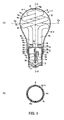
- a self-ballasted fluorescent lamp L1 comprises a lamp base including an annular cover 2, and an E-type screw fitting or ferrule (1) held with a fixation unit such as an adhesive agent and caulking at one end of a lamp-axial direction of the cover 2, a holder 3 attached in the cover 2, a light-emitting tube 4 which is a fluorescent lamp supported on the other end side of the holder 3, a lighting device 5 housed in the cover 2, a globe 6 which covers the light-emitting tube 4, and the like.
- a fixation unit such as an adhesive agent and caulking at one end of a lamp-axial direction of the cover 2
- a holder 3 attached in the cover 2
- a light-emitting tube 4 which is a fluorescent lamp supported on the other end side of the holder 3
- a lighting device 5 housed in the cover 2
- a globe 6 which covers the light-emitting tube 4, and the like.
- the self-ballasted fluorescent lamp L1 has a rated lamp power of 10W, and is formed into dimensions and an appearance close to those of a general illumination light bulb such as an incandescent light bulb equivalent to 60W.
- This general illumination light bulb is defined by JIS C 7501.
- one end side of a lamp-axial direction where a ferrule 1 is arranged is referred to as the lower side
- the other end side of a lamp-axial direction where a light-emitting tube 4 is arranged is referred to as the upper side in the following explanations.
- a light-emitting tube 4 has a spiral part 4a, which is a swelling part formed at the upper part side and a pair of straight tube parts 4b, 4c, which have a substantially linear shape formed at the lower part side, and these are formed in an integrated manner.
- a tube outer diameter of the light-emitting tube 4 is 6mm to 9mm, and the light-emitting tube 4 is formed, for example, by bending while heating and an integrated manner.
- a tube outer diameter of the light-emitting tube 4 is 6mm to 9mm, and the light-emitting tube 4 is formed, for example, by bending while heating and fusing glass bulb 4d, which has an 8.5mm tube outer diameter and is a cylindrical tubular and straight, into two in substantially even lengths; by folding the bent bulb around a die (not shown), so that a folded part 4f, which is an equally-divided position, becomes a top part of the bulb; and by molding into a double-spiral shape, which has a substantially circular truncated cone shape having a concentric-axial stretched with superimposed different diameters.
- a spiral part 4a is formed as a double-spiral shape having a first turning part 4a-1, which goes up from one end of a bulb 4d to a folded part 4f, which is an upper top of the spiral part 4a, while turning around a lamp axis O-O (or a turning axis O-O of the spiral part 4a) and reducing the spiral diameter gradually; and a second turning part 4a-2, which goes down from the other end of the folded part 4f to the other end of a bulb 4d while turning around the lamp axis O-O and increasing the spiral diameter gradually; and is formed as, for example, substantially turning twice.
- a virtual shape of the outside of the spiral part 4a has a substantially circular truncated cone shape, the spiral part 4a is formed into a shape having the greatest diameter part 4i in the lower part of the spiral part 4a.
- This spiral shape forms a long discharge path regardless of its small size.
- the spiral part 4a is arranged so that both turning parts of the spiral part 4a face each other along the inner surface of the globe 6 at a top 6g side of the globe 6 including the greatest diameter part 6c.
- the greatest diameter part 4i of the spiral part 4a is formed so that the diameter is greater than an inner diameter of a decreased diameter part 6e of the globe 6.
- both ends 4g, 4h of a bulb 4d are bent substantially parallel along a lamp axis O-O, and a pair of straight tube parts 4b, 4c, which has a short and substantially straight discharge path, are formed from the spiral part 4a.
- a single, long, continuous discharge path from the straight tube part 4b through the spiral part 4a to the straight tube part 4c is formed in the bulb 4d.
- this pair of straight tube parts 4b, 4c are arranged into a decreased diameter part 6e side of the globe 6.
- a diameter ⁇ 2 of a virtual circle see Fig.
- electrode sealing ends 4s, 4t in which a pair of electrodes 4q, 4r are sealed, respectively, are formed.
- filamentous coiled-electrodes of tungsten are used as the pair of electrodes 4q, 4r, and the pair of electrodes 4q, 4r is sealed and adhered to the electrode sealing ends 4s, 4t of both ends of the temporarily attached bulb 4d by a flared stem.
- an ultraviolet absorbing film 4n for example, mainly including microparticles of titanium oxide (TiO 2 ) and zinc oxide (ZnO) is formed over substantially the entire length of an inner wall surface 4d-1 of the bulb 4d.
- a phosphor layer 4m composed of a film of phosphor such as rare-earth metal oxides, is formed on the ultraviolet absorbing film 4n.
- ultraviolet absorbing film 4n is composed of particles that contain, for example, titanium oxide with an average particle diameter of 0.03 ⁇ m to 0.05 ⁇ m and zinc oxide with an average particle diameter of 0.015 ⁇ m to 0.05 ⁇ m, and at a mixing ratio of 50% for each by weight.
- a film thickness of the ultraviolet absorbing film 4n is 0.1 ⁇ m to 2 ⁇ m, and preferably 0.3 ⁇ m to 0.5 ⁇ m.
- the film thickness of the ultraviolet absorbing film 4n is a thickness at an inner surface of the upper side tube body of the bulb 4d, that is, at the P point in Fig. 3(a) (film thickness of an inner surface of the lower side tube body tends to be thicker).
- no protective film is formed in the present embodiment; however, a protective film of alumina or the like may be formed between the bulb 4d and the ultraviolet absorbing film 4n.
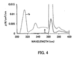
- Fig. 4 shows a measurement result of ultraviolet light output ( ⁇ W/cm 2 /nm) of a light-emitting tube 4 of the present embodiment when lighting by exposing the light-emitting tube 4 without a globe.
- a curve (solid line) "a” is a characteristic curve of a light-emitting tube 4 of the present embodiment
- a curve (dashed line) b is a characteristic curve of an everyday product which is not formed with an ultraviolet absorbing film 4n.
- the light-emitting tube 4 of the embodiment of the present invention As compared with the everyday product, in the light-emitting tube 4 of the embodiment of the present invention, bright lines of Hg at a wavelength of 365nm or lower and light at a wavelength of approximately 400nm or lower are reduced, and ultraviolet components are well absorbed from an ultraviolet range to a short-wavelength range of visible light. In other words, it is shown that ultraviolet-absorption action is good.
- a light-emitting tube 4 which is formed with an ultraviolet absorbing film 4n, can reduce bright lines of Hg at a wavelength of 365nm or lower, which affects deterioration of a synthetic resin the most, and light at a wavelength of 400nm or lower, and can absorb ultraviolet components from an ultraviolet range to a short-wavelength range of visible light.
- a synthetic-resin globe 6 is protected from ultraviolet light radiated from a light-emitting tube 4, and deterioration such as a change and deterioration in color, decrease in transmittance, and embrittlement of the globe 6 caused by ultraviolet light can be prevented.
- a discharge medium such as argon and krypton
- fine tubes 4u, 4v are provided in a protruding manner on end surfaces of a pair of electrode sealing ends 4s, 4t.
- the fine tubes 4u, 4v continuously communicate with the inside of the electrode sealing ends 4s, 4t, and contain mercury and amalgam internally.
- a fine tube 4w for exhaust is provided in a protruding manner at a folded part 4f, which is a top part of a spiral part4a. Meanwhile, the temperature-reduced part may be formed at the folded part 4f.
- the fine tube 4w may contain mercury and amalgam internally.
- a rated lamp power of a self-ballasted fluorescent lamp L1 is 10W
- a light-emitting tube 4 has diameter dimensions ⁇ 1 that at the greatest diameter part 4i are approximately 50mm
- height h1 is approximately 64mm
- height h2 from a horizontal central axis of the greatest diameter part 4i to an end surface of a pair of electrode sealing end 4s, 4t is approximately 40mm.
- a discharge-path length between a pair of electrodes 4q, 4r is 200mm to 400mm, and is different depending on the tube outer diameter of a bulb 4d. For example, when a tube outer diameter of a bulb 4d is 8mm, a discharge-path length is 350mm, and when a tube outer diameter is 9mm, a discharge-path length is 320mm.
- a light-emitting tube 4 is supported by a holder 3 in a cover 2 fixed at a ferrule 1.
- the ferrule 1 is an Edison E-26 type or the like, and includes a cylindrical shell 1a having a screw thread, and an electrical contact 1c which is provided on a top of one end side of the shell 1a via an insulating part 1b.
- the shell 1a is made up of conductive metals such as a copper plate, the other end side of the shell 1a covers one end of a cover 2 and is fixed by a unit including a thermotolerant adhesive agent such as a silicon resin and an epoxy resin, or caulking.
- a cover 2 has a cover main body 2a formed with thermotolerant synthetic resin materials, for example, polybutylene terephthalate (PBT) and the like.
- the shell 1a of the ferrule 1 is attached to the lower end side of the cover main body 2a, an annular attaching end 2b is formed at the upper end side of the cover main body 2a.
- the attaching end 2b forms an inverted circular truncated cone, which gradually decreases in diameter toward the bottom, and is composed so that an opening end 6d of a base end side of a globe 6 is fitted.
- a step part 2c which sets and fixedly attaches the under side of a holder 3 with a thermotolerant adhesive agent such as a silicon resin and an epoxy resin in the attaching end 2b, is formed.
- a holder 3 is formed into a covered cylinder shape with thermotolerant synthetic resin materials, for example, polybutylene terephthalate (PBT) and the like, and a cylindrical part 3b, which is a cylindrical shape protruding to the lower end side, is formed at a lower surface periphery of a disk-shaped basal plate 3a forming a cover part is an integrated manner.
- the lower end of the cylindrical part 3b is placed on the step part 2c of the cover main body 2a, and fixedly attached with a thermotolerant adhesive agent such as a silicon resin and an epoxy resin.
- a light-emitting tube 4 is placed and supported on a basal part 3a.
- the holder 3 has a recessed part 3c, where the lower end part of a pair of straight tube parts 4b, 4c in the light-emitting tube 4 are placed and supported, and a cylindrical projecting part 3d, which limits diametral displacement of the straight tube parts 4b, 4c projected in a gap between the lower end parts of straight tube parts 4b, 4c is provided in a protruding manner. Furthermore, through holes are formed outside of the each cylindrical projecting part 3d at the basal plate 3a.
- Fine tubes 4u, 4v projected from a pair of electrode sealing ends 4s, 4t of the light-emitting tube 4 to the outside thereof, and outer wires 4x, 4y connected to electrodes 4q, 4r are inserted to the through holes, respectively.
- a pair of straight tube parts 4b, 4c of the light-emitting tube 4 is fixedly attached with a thermotolerant adhesive agent such as a silicon resin on the basal plate 3a of the holder 3.
- the cover 2 and the holder 3 are configured independently, but they may be formed in an integrated manner with a synthetic resin.
- a circuit board 5a formed with a lighting circuit pattern to control lighting of a light-emitting tube 4 is fitted and fixed into a pair of longitudinal grooves 2d, 2d located inside of a cover 2 in a longitudinal direction along a direction of a lamp axis.
- the circuit pattern is formed on one side or both sides of the circuit board 5a, and a plurality of electronic components 5b consisting of the lighting circuit, including lead components such as an electrolyte capacitor and chip components such as a transistor, are mounted on a mounting surface of the circuit board 5a.
- a globe 6 is, for example, transparent or translucent white with a light diffusion, has translucency, and is formed with a thermoplastic synthetic resin such as polycarbonate.
- the globe 6 is also formed into a circular PS (pear-shape)-type bulb shape, which is used for a general illumination light bulb etc., such as an incandescent light bulb and has a circular cross-section, and is formed into a smooth curved-surface the same as a glass globular shape in a general illumination light bulb such as an incandescent light bulb.
- the globe 6 has a globular part 6a, which is formed into a substantially globular shape having the greatest diameter part 6c at a top 6g side, and a substantially cylindrical-shaped basal part 6b, which has a decreased diameter part 6e whose diameter is gradually decreased to smaller than the diameter of the greatest diameter part 6c of the globular part 6a, at an opening end 6d side of a base end side, formed in an integrated manner.
- a wall thickness of the globe 6 is from 0.5mm to 1.5mm, and a wall thickness in the present embodiment is approximately 1. 5mm and an outer diameter D1 of the greatest diameter part 6c is approximately 55mm.
- Deterioration of a synthetic-resin globe 6 caused by ultraviolet light radiated from the light-emitting tube 4 is prevented by forming an ultraviolet absorbing film 4n on the light-emitting tube 4.
- deterioration of a globe 6 is prevented with double actions of ultraviolet absorption of both an ultraviolet absorbing film 4n of the light-emitting tube 4 and an ultraviolet absorbable globe 6 by making the globe 6 with a synthetic-resin added to an ultraviolet absorber.
- the ultraviolet absorber used for the globe 6 includes benzoate, cinnate, benzotriazole, and oxanilide compounds etc.
- the ultraviolet absorber may contain an ultraviolet-absorbable resin, which can absorb ultraviolet light by the resin per se, for example, a copolymer containing a first monomer M consisting of carbonate esters and a second monomer M' having an ultraviolet absorbing function.
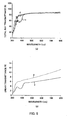
- Fig. 5(a) and Fig. 5(b) show measurement results of transmittance of light to wavelength in a synthetic-resin globe 6, which is added to an ultraviolet absorber of the present embodiment and has a wall thickness of approximately 1.5mm.
- a curve (solid line) c is a characteristic curve of a synthetic-resin globe 6 in the present embodiment
- a curve (dashed line) d is a characteristic curve of a conventional glass globe without adding an ultraviolet absorber.
- Fig. 5 (a) shows a total ray transmittance
- Fig. 5(b) shows a linear transmittance.
- the synthetic-resin globe 6 of the present embodiment As compared with the conventional glass globe, in the synthetic-resin globe 6 of the present embodiment, bright lines of Hg at a wavelength of around 365nm which affects deterioration of a synthetic resin are reduced, and ultraviolet components are well absorbed from an ultraviolet range to a short-wavelength range of visible light. In other words, it is shown that ultraviolet-absorption action is good.
- a synthetic-resin globe 6 which is added to an ultraviolet absorber, can reduce bright lines of Hg at a wavelength of around 365nm, which affects deterioration of a synthetic resin, and can well absorb ultraviolet components from a range of an ultraviolet range to a short-wavelength range of visible light.
- a synthetic-resin globe 6 is protected from ultraviolet light radiated from a light-emitting tube 4, and deterioration such as a change and deterioration in color, decrease in transmittance, and embrittlement of the globe 6 caused by ultraviolet light can be prevented.
- the globe 6 is divided at the greatest diameter part 6c of the globe 6 and on a dividing line Oa-Oa, bisecting at right angles to a lamp axis O-O of a light-emitting tube 4 (a shaft center of the globe 6) into two parts of a top globe 6-1, which is an upper half, i.e., a top 6g side of the globe 6; and a bottom globe 6-2, which is a lower half, i.e., a decreased diameter part 6e side of the globe 6.
- a globe 6 is formed as an integrated piece without dividing, a light-emitting tube 4 cannot be inserted from an opening end 6d because an outer diameter ⁇ 1 of the greatest diameter part 4i of the light-emitting tube 4 is larger than an opening diameter of the opening end 6d of the globe 6.
- the globe 6 is divided into two parts of the top globe 6-1 and the bottom globe 6-2 above and below at the dividing line Oa-Oa. Therefore, after supporting straight tube parts 4b, 4c of the light-emitting tube 4 with a holder 3, the holder 3 and the straight tube parts 4b, 4c of the light-emitting tube 4 can be inserted from a wide opening-end formed by dividing of the bottom globe 6-2 toward the opening end 6d.
- the bottom globe 6-2 is covered with the top globe 6-1, and then, divided and joined surfaces of each opening end of the both globes 6-1, 6-2 can be attached by ultrasonic welding to be integrated.
- a projecting part 6-1b is annularly formed on the divided and joined surface 6-2a of the bottom globe 6-2.
- a recessed part 6-2b is annularly formed on the divided and joined surface 6-2a of the bottom globe 6-2.
- the projecting part 6-1b is fused instantaneously by frictional heat generated by application of a lengthwise ultrasonic vibration, and with the divided and joined surfaces 6-1a, 6-2a attached by welding to each other.
- welding of the divided and joined surfaces 6-1a, 6-2a may be achieved by other welding methods such as vibration welding.
- the divided and joined surfaces 6-1a, 6-2a require a predetermined width, in other words, the globe 6 requires a predetermined wall thickness.
- an opening end 6d is formed at a basal part 6b, in other words, at the base end side.
- a edge part of the opening end 6d as well as a cylindrical part 3b of the holder 3 are fitted inside an attaching end 2b of a cover 2, and are fixed with a thermotolerant adhesive agent such as a silicon resin and an epoxy resin, for example.
- a thermotolerant adhesive agent such as a silicon resin and an epoxy resin, for example.
- a light-emitting tube 4 of a self-ballasted fluorescent lamp L1 it is required to arrange a light-emitting tube 4 of a self-ballasted fluorescent lamp L1 along an inner surface of a globe 6 as close as possible, so as to elongate a discharge-path length thereof.
- the light-emitting tube 4 is too close to the inner surface of a globe 6, the globe 6 is easily discolored, etc., by heat and leaked ultraviolet light from the light-emitting tube 4. Therefore, it is necessary to control spacing dimensions between an outer surface of the light-emitting tube 4 and the inner surface of the globe 6, to the predetermined dimensions.
- set is a spacing dimension between an outer surface of a folded part 4f, which is a top of the light-emitting tube 4, and the closest inner surface of the globe 6 is approximately 2mm to 3mm; a spacing dimension between an outer surface of the greatest diameter part 4i of the light-emitting tube 4 and the closest inner surface of the globe 6 is approximately 3mm to 4mm; and a spacing dimension between an outer surface of straight tube part 4b, 4c and the closest inner surface of the globe 6 is approximately 2mm to 3mm.
- dimensions of a self-ballasted fluorescent lamp L1 configured as mentioned above are, for example, a total length H1 (including a ferrule 1) of approximately 109mm, and diameter dimension D1 of the greatest diameter part 4i which is swelled and has a globular shape of approximately 55mm. Furthermore, dimensions of a self-ballasted fluorescent lamp L1, to which the invention is applicable, have a total length H1 (including a ferrule 1) at preferably 110mm or less, and diameter dimension D1 of the greatest diameter part 4i which is swelled at preferably 60mm or less.
- a self-ballasted fluorescent lamp L1 when a self-ballasted fluorescent lamp L1 is lit, in ultraviolet light radiated from a light-emitting tube 4, by an ultraviolet absorbing film 4n formed between an inner surface 4d-1 of the bulb 4d and a phosphor layer 4m, as a characteristic curve shown in Fig. 4 , bright lines of Hg at a wavelength of 365nm or less which affects deterioration of a synthetic resin the most and light at a wavelength of 400nm or less are reduced, and ultraviolet components are well absorbed from an ultraviolet range to a short-wavelength range of visible light. Then, this ultraviolet-absorbed light ray is radiated to the globe 6. As a result, deterioration of the globe 6 can be prevented even when a self-ballasted fluorescent lamp L1 is further miniaturized, and a bulb 4d of a light-emitting tube 4 and the globe 6 come closer to each other.
- a globe 6 added to an ultraviolet absorber has an absorption wavelength of approximately 350mm to approximately 450nm as shown in Fig. 5(a) and Fig. 5(b) , and therefore, the globe 6 can also absorb ultraviolet components in a short-wavelength range of visible light, which are unable to be absorbed by an ultraviolet absorbing film 4n of a light-emitting tube 4.
- a self-ballasted fluorescent lamp L1 has an ultraviolet light output of substantially zero at a wavelength of approximately 300mm to approximately 400nm by these double actions of ultraviolet absorption, and therefore, ultraviolet light is well absorbed. As a result, sufficient light flux can be obtained for a long time.
- Fig. 7 shows a measurement result of ultraviolet light output ( ⁇ W/cm 2 /nm) of a self-ballasted fluorescent lamp L1 of the present embodiment.
- a curve (solid line) e is a characteristic curve of a self-ballasted fluorescent lamp L1 of the present embodiment
- a curve (dashed line) f is a characteristic curve of an everyday product, which has no ultraviolet absorbing film 4n in a light-emitting tube 4, and an ultraviolet absorber is not added to the globe 6.
- ultraviolet light output of the self-ballasted fluorescent lamp L1 of the present embodiment is low and substantially zero.
- a self-ballasted fluorescent lamp L1 can prevent insects from flying toward light effectively because a self-ballasted fluorescent lamp L1 can make ultraviolet light output substantially zero at a wavelength of approximately 300mm to approximately 400nm. That is, Fig. 8 is a graph showing spectral intensity distributions of various types of lamps and a relative spectral sensitivity of insects to wavelength in relative intensity.
- a curve (solid line) e is a characteristic curve of a self-ballasted fluorescent lamp L1 of the present embodiment
- a curve (dashed line) f is a characteristic curve of an everyday product, which has no ultraviolet absorbing film 4n in a light-emitting tube 4, and an ultraviolet absorber is not added to the globe 6
- a curve (dashed line with a dot) g is a relative spectral sensitivity curve representing relative spectral sensitivity of insects
- a curve (dashed line with two dots) h is a characteristic curve of an incandescent light bulb.
- a self-ballasted fluorescent lamp L1 of the present embodiment has ultraviolet light output of substantially zero at a wavelength of approximately 300mm to approximately 400nm, in other words, ultraviolet light, which has a high level of relative spectral sensitivity of insects, are substantially 100% eliminated. Therefore, the self-ballasted fluorescent lamp L1 can prevent insects from flying toward light effectively.
- Fig. 9 measurement results of insect-attracting rates, discoloring-damage rates of globe 6, and intensities of UV light irradiation in a self-ballasted fluorescent lamp L1 of the present embodiment, an everyday product, and an incandescent light bulb are shown in Fig. 9 .
- insect-attracting rates, and discoloring-damage rates of globe 6 are percents (%) of a self-ballasted fluorescent lamp L1 of the present embodiment and an everyday product represented as a result of an incandescent light bulb as 100.
- the self-ballasted fluorescent lamp L1 of the present embodiment and the everyday product are corresponding to a 60W incandescent light bulb.
- the self-ballasted fluorescent lamp L1 of the present embodiment considerably decreased intensities of ultraviolet light irradiation and also reduced discoloring-damage rates of globe 6 to substantially half or less, and insect-attracting rates were also low as compared with an everyday product, which has no ultraviolet absorbing film in a conventional light-emitting tube 4, and an ultraviolet absorber is not added to the globe 6. Therefore, a low insect-attracting type self-ballasted fluorescent lamp L1 can be successfully configured.
- a wall thickness of a globe 6 is set at 1.5mm.
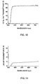
- Measurement results of total ray transmittance and linear transmittance in the globe 6 are shown in Figs. 10 and 11 .
- the relationship between wavelength (horizontal axis) and total ray transmittance (vertical axis) are represented as actual measurements
- the relationship between the wavelength (horizontal axis) and linear transmittance (vertical axis) are represented as actual measurements.
- measured values of total ray transmittance and linear transmittance at a wavelength of 400mm to 800nm are obtained as shown in Fig. 12 . Based on these measured values, results showed that total ray transmittance was 87% on average for a visible light region (450nm to 800nm), and linear transmittance was 4.6% on average for a visible light region (450nm to 800nm).
- a wall thickness of a globe 6 was 0.5mm to 1. 5mm, total ray transmittance in a visible light region was 85% or higher, and linear transmittance was 10% or lower.
- a predetermined wall thickness is required for welding of the divided and joined surfaces 6-1a, 6-2a in the globe 6.
- the wall thickness of the globe 6 is less than 0.5mm, the wall thickness does not satisfy a predetermined wall thickness from the viewpoint of maintenance of welding intensity, etc., in addition, an increase in the linear transmittance resulted.
- the globe 6 has a wall thickness from 0.5mm to 1. 5mm, and in view of the fact that ranges of a wall thickness, total ray transmittance and linear transmittance in a globe 6 affect a wall thickness required for welding, and thus the wall thickness affects total ray transmittance and linear transmittance, the desired effect can be achieved by combining these factors organically.
- a self-ballasted fluorescent lamp L1 an approximate appearance to a general illumination light bulb, can be obtained. Also, a spiral part 4a of a light-emitting tube 4 can be increased for both bulb diameters and spiral diameters, because a spiral part 4a of a light-emitting tube 4 is housed in a globular part 6a including the greatest diameter part 6c of a globe 6, which has a comparatively large capacity. As a result, a discharge path length of a spiral part 4a can be extended, luminous flux at a spiral part 4a can be increased, and luminous efficiency can be improved.
- an image projection of a shape of a light-emitting tube 4 on a globe 6 can be prevented, a dividing line Oa-Oa of a globe 6 can be less obvious, and a decrease in appearance can be prevented by configuring the globe 6 in the optimum values ranges of a wall thickness, total ray transmittance, and linear transmittance.
- straight tube parts 4b, 4c of the light-emitting tube 4 are prone to darken as compared with a spiral part 4a, however, improvement proved possible because of action of the diffused light by an increase of diffused transmittance of the globe 6.
- divided and joined surfaces 6-1a, 6-2a of the globe 6 can be jointed without requiring particular process materials such as an adhesive agent, and joined easily, rapidly, strongly, and homogeneously because the divided and joined surfaces 6-1a, 6-2a of the globe 6 are joined by ultrasonic welding, and a dividing line Oa-Oa itself of the globe 6 can also be less obvious.
- the divided and joined surface 6-1a, 6-2a of a globe 6 when the globe 6 is divided at a dividing line Oa-Oa is shown in Fig. 13(a) .
- a diameter dimension D1 of this divided and joined surface 6-1a, 6-2a is larger than that of the greatest diameter part 4i of a spiral part 4a of a light-emitting tube 4.
- a diameter dimension D2 of this divided and joined surface is larger than that of the greatest diameter part 4i of a spiral part 4a of a light-emitting tube 4.
- the aspect of dividing is not limited to the above-mentioned aspect. In other words, it may be allowed that the entire light-emitting tube 4 having a spiral part 4a is covered with globe 6 by dividing the globe 6.
- An illumination apparatus 20 is, for example, a downlight, and has an apparatus main body 21, and a socket 22 and a reflector 23 are attached to the apparatus main body 21.
- a ferrule 1 of a self-ballasted fluorescent lamp L1 is fitted with the socket 22 by screwing.
- a self-ballasted fluorescent lamp L1 is formed into a shape approximated to or the same as a general illumination light bulb such as an incandescent light bulb, it is allowed that light distribution of the apparatus is approximated to or the same as light distribution of a general illumination light bulb, and therefore, irradiance of light to a reflector 23 located adjacent to a socket 22 is sufficiently ensured, and property of the apparatus can be obtained as an optical design of the reflector. Moreover, the self-ballasted fluorescent lamp L1 can improve illuminance below the lamp because a spiral part 4a of a light-emitting tube 4 is directed downward.
- an ultraviolet light radiated from the light-emitting tube 4 is doubly absorbed by both an ultraviolet absorbing film 4n of the light-emitting tube 4 and a synthetic resin globe 6 added to an ultraviolet absorber, as a result, deterioration such as a change and deterioration in color, decrease in transmittance, and embrittlement of the apparatus main body 21, the socket 22, and reflector 23 etc., in the self-ballasted fluorescent lamp L1.
- the self-ballasted fluorescent lamp L1 is configured as a lamp-of a low insect-attracting type, and therefore, the lamp can prevent insects from flying toward light.
- the self-ballasted fluorescent lamp L1 can prevent dirtying of the apparatus, especially dirtying of a reflector, a globe, and a shade, etc., caused by insects, and thus, it can save effort in cleaning the apparatus and desired bright lighting is available for a long time.
- an illumination apparatus with a shade having a function of ultraviolet light protection and a self-ballasted fluorescent lamp L1 of a low insect-attracting type are used, further effect to prevent insects from flying toward light by double low insect-attracting effects of the shade and the self-ballasted fluorescent lamp L1 can be provided.
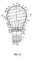
- FIG. 15 a second embodiment of the present invention is shown in Fig. 15 .
- a self-ballasted fluorescent lamp L1 of the second embodiment of the present invention has the same basic constitution as a self-ballasted fluorescent lamp L1 of the first embodiment, however, in particular, the shape of a light-emitting tube 4 differs from each other.
- a spiral part 4a of a light-emitting tube 4 reduces spacing around a bulb 4d, and the spiral part 4a is arranged even in a space close to electrodes 4q, 4r.
- a discharge-path length of the light-emitting tube 4 becomes longer and luminous efficiency can be improved, as well as light distribution properties, which are approximated to, or the same as a general illumination light bulb can be obtained because the light-emitting tube 4 is formed into a shape arranged along an inner surface of a globe 6.
Landscapes
- Engineering & Computer Science (AREA)
- Manufacturing & Machinery (AREA)
- Vessels And Coating Films For Discharge Lamps (AREA)
- Non-Portable Lighting Devices Or Systems Thereof (AREA)
Applications Claiming Priority (3)
| Application Number | Priority Date | Filing Date | Title |
|---|---|---|---|
| JP2008049411A JP2009206027A (ja) | 2008-02-29 | 2008-02-29 | 電球形蛍光ランプ及び照明装置 |
| JP2008073643 | 2008-03-21 | ||
| JP2008197510A JP2009259766A (ja) | 2008-03-21 | 2008-07-31 | 電球形蛍光ランプおよび照明器具 |
Publications (3)
| Publication Number | Publication Date |
|---|---|
| EP2105947A2 true EP2105947A2 (de) | 2009-09-30 |
| EP2105947A3 EP2105947A3 (de) | 2009-12-30 |
| EP2105947B1 EP2105947B1 (de) | 2011-01-26 |
Family
ID=40956698
Family Applications (1)
| Application Number | Title | Priority Date | Filing Date |
|---|---|---|---|
| EP20090250518 Not-in-force EP2105947B1 (de) | 2008-02-29 | 2009-02-26 | Kompakt-Leuchtstofflampe und Beleuchtungsvorrichtung |
Country Status (1)
| Country | Link |
|---|---|
| EP (1) | EP2105947B1 (de) |
Citations (2)
| Publication number | Priority date | Publication date | Assignee | Title |
|---|---|---|---|---|
| JP2005174637A (ja) | 2003-12-09 | 2005-06-30 | Toshiba Lighting & Technology Corp | 電球形蛍光ランプ、及び照明器具 |
| JP2008010404A (ja) | 2006-05-31 | 2008-01-17 | Toshiba Lighting & Technology Corp | 電球形蛍光ランプおよび照明装置 |
Family Cites Families (4)
| Publication number | Priority date | Publication date | Assignee | Title |
|---|---|---|---|---|
| DE10026909A1 (de) * | 2000-05-31 | 2001-12-06 | Philips Corp Intellectual Pty | Niederdruck-Quecksilber-Entladungslampe mit Aussenkolben |
| US20020057059A1 (en) * | 2000-07-28 | 2002-05-16 | Kazuhisa Ogishi | Fluorescent lamp, self-ballasted fluorescent lamp and lighting apparatus |
| WO2006006097A2 (en) * | 2004-07-05 | 2006-01-19 | Koninklijke Philips Electronics N.V. | Compact fluorescent lamp |
| JP2006100107A (ja) * | 2004-09-29 | 2006-04-13 | Hitachi Lighting Ltd | 蛍光ランプ |
-
2009
- 2009-02-26 EP EP20090250518 patent/EP2105947B1/de not_active Not-in-force
Patent Citations (2)
| Publication number | Priority date | Publication date | Assignee | Title |
|---|---|---|---|---|
| JP2005174637A (ja) | 2003-12-09 | 2005-06-30 | Toshiba Lighting & Technology Corp | 電球形蛍光ランプ、及び照明器具 |
| JP2008010404A (ja) | 2006-05-31 | 2008-01-17 | Toshiba Lighting & Technology Corp | 電球形蛍光ランプおよび照明装置 |
Also Published As
| Publication number | Publication date |
|---|---|
| EP2105947B1 (de) | 2011-01-26 |
| EP2105947A3 (de) | 2009-12-30 |
Similar Documents
| Publication | Publication Date | Title |
|---|---|---|
| US8324790B1 (en) | High illumination LED bulb with full emission angle | |
| JP2004103461A (ja) | 放電バルブ用アークチューブ | |
| CN101521140A (zh) | 灯泡形荧光灯以及照明器具 | |
| CN101405539A (zh) | 用于聚光照明的高强度放电灯 | |
| TW561231B (en) | Discharge lamp device and lighting device | |
| EP2105947B1 (de) | Kompakt-Leuchtstofflampe und Beleuchtungsvorrichtung | |
| US8680756B2 (en) | Optical system for a luminaire | |
| US20020149931A1 (en) | Energy-saving conic lamp | |
| CN100530513C (zh) | 低压汞蒸气灯 | |
| CN101668985B (zh) | 灯泡型荧光灯 | |
| JP2002015700A (ja) | 蛍光ランプおよび蛍光ランプ装置 | |
| TW200935488A (en) | Backlight and illuminating device | |
| CN101236882B (zh) | 灯泡形荧光灯以及照明装置 | |
| JP2008226814A (ja) | 電球形蛍光ランプおよび照明器具 | |
| JP3686793B2 (ja) | バックライトユニット | |
| JP2002093589A (ja) | 放電ランプ装置および照明装置 | |
| JP2001155527A (ja) | バックライト装置および液晶表示装置 | |
| JP2008004398A (ja) | 電球形蛍光ランプおよび照明器具 | |
| CN224175030U (zh) | 一种无影灯 | |
| US5345140A (en) | Electric lamp arrangement with reflector | |
| JP5335031B2 (ja) | 全射角高照度ledバルブ | |
| JPS6070655A (ja) | 小形高圧放電灯装置 | |
| JP2006310084A (ja) | 蛍光ランプ及び照明器具 | |
| CN214147467U (zh) | Led灯丝与led球泡灯 | |
| CN101346797A (zh) | 照明装置以及金属蒸汽放电灯 |
Legal Events
| Date | Code | Title | Description |
|---|---|---|---|
| PUAI | Public reference made under article 153(3) epc to a published international application that has entered the european phase |
Free format text: ORIGINAL CODE: 0009012 |
|
| 17P | Request for examination filed |
Effective date: 20090309 |
|
| AK | Designated contracting states |
Kind code of ref document: A2 Designated state(s): AT BE BG CH CY CZ DE DK EE ES FI FR GB GR HR HU IE IS IT LI LT LU LV MC MK MT NL NO PL PT RO SE SI SK TR |
|
| AX | Request for extension of the european patent |
Extension state: AL BA RS |
|
| PUAL | Search report despatched |
Free format text: ORIGINAL CODE: 0009013 |
|
| AK | Designated contracting states |
Kind code of ref document: A3 Designated state(s): AT BE BG CH CY CZ DE DK EE ES FI FR GB GR HR HU IE IS IT LI LT LU LV MC MK MT NL NO PL PT RO SE SI SK TR |
|
| AX | Request for extension of the european patent |
Extension state: AL BA RS |
|
| 17Q | First examination report despatched |
Effective date: 20100419 |
|
| GRAP | Despatch of communication of intention to grant a patent |
Free format text: ORIGINAL CODE: EPIDOSNIGR1 |
|
| AKX | Designation fees paid |
Designated state(s): AT BE BG CH CY CZ DE DK EE ES FI FR GB GR HR HU IE IS IT LI LT LU LV MC MK MT NL NO PL PT RO SE SI SK TR |
|
| GRAS | Grant fee paid |
Free format text: ORIGINAL CODE: EPIDOSNIGR3 |
|
| GRAA | (expected) grant |
Free format text: ORIGINAL CODE: 0009210 |
|
| AK | Designated contracting states |
Kind code of ref document: B1 Designated state(s): AT BE BG CH CY CZ DE DK EE ES FI FR GB GR HR HU IE IS IT LI LT LU LV MC MK MT NL NO PL PT RO SE SI SK TR |
|
| REG | Reference to a national code |
Ref country code: GB Ref legal event code: FG4D |
|
| REG | Reference to a national code |
Ref country code: CH Ref legal event code: EP |
|
| REG | Reference to a national code |
Ref country code: IE Ref legal event code: FG4D |
|
| REF | Corresponds to: |
Ref document number: 602009000654 Country of ref document: DE Date of ref document: 20110310 Kind code of ref document: P |
|
| REG | Reference to a national code |
Ref country code: DE Ref legal event code: R096 Ref document number: 602009000654 Country of ref document: DE Effective date: 20110310 |
|
| REG | Reference to a national code |
Ref country code: NL Ref legal event code: T3 |
|
| LTIE | Lt: invalidation of european patent or patent extension |
Effective date: 20110126 |
|
| PG25 | Lapsed in a contracting state [announced via postgrant information from national office to epo] |
Ref country code: ES Free format text: LAPSE BECAUSE OF FAILURE TO SUBMIT A TRANSLATION OF THE DESCRIPTION OR TO PAY THE FEE WITHIN THE PRESCRIBED TIME-LIMIT Effective date: 20110507 Ref country code: HR Free format text: LAPSE BECAUSE OF FAILURE TO SUBMIT A TRANSLATION OF THE DESCRIPTION OR TO PAY THE FEE WITHIN THE PRESCRIBED TIME-LIMIT Effective date: 20110126 Ref country code: LT Free format text: LAPSE BECAUSE OF FAILURE TO SUBMIT A TRANSLATION OF THE DESCRIPTION OR TO PAY THE FEE WITHIN THE PRESCRIBED TIME-LIMIT Effective date: 20110126 Ref country code: GR Free format text: LAPSE BECAUSE OF FAILURE TO SUBMIT A TRANSLATION OF THE DESCRIPTION OR TO PAY THE FEE WITHIN THE PRESCRIBED TIME-LIMIT Effective date: 20110427 Ref country code: LV Free format text: LAPSE BECAUSE OF FAILURE TO SUBMIT A TRANSLATION OF THE DESCRIPTION OR TO PAY THE FEE WITHIN THE PRESCRIBED TIME-LIMIT Effective date: 20110126 Ref country code: PT Free format text: LAPSE BECAUSE OF FAILURE TO SUBMIT A TRANSLATION OF THE DESCRIPTION OR TO PAY THE FEE WITHIN THE PRESCRIBED TIME-LIMIT Effective date: 20110526 Ref country code: SE Free format text: LAPSE BECAUSE OF FAILURE TO SUBMIT A TRANSLATION OF THE DESCRIPTION OR TO PAY THE FEE WITHIN THE PRESCRIBED TIME-LIMIT Effective date: 20110126 Ref country code: NO Free format text: LAPSE BECAUSE OF FAILURE TO SUBMIT A TRANSLATION OF THE DESCRIPTION OR TO PAY THE FEE WITHIN THE PRESCRIBED TIME-LIMIT Effective date: 20110426 |
|
| PG25 | Lapsed in a contracting state [announced via postgrant information from national office to epo] |
Ref country code: CY Free format text: LAPSE BECAUSE OF FAILURE TO SUBMIT A TRANSLATION OF THE DESCRIPTION OR TO PAY THE FEE WITHIN THE PRESCRIBED TIME-LIMIT Effective date: 20110126 Ref country code: FI Free format text: LAPSE BECAUSE OF FAILURE TO SUBMIT A TRANSLATION OF THE DESCRIPTION OR TO PAY THE FEE WITHIN THE PRESCRIBED TIME-LIMIT Effective date: 20110126 Ref country code: BE Free format text: LAPSE BECAUSE OF FAILURE TO SUBMIT A TRANSLATION OF THE DESCRIPTION OR TO PAY THE FEE WITHIN THE PRESCRIBED TIME-LIMIT Effective date: 20110126 Ref country code: BG Free format text: LAPSE BECAUSE OF FAILURE TO SUBMIT A TRANSLATION OF THE DESCRIPTION OR TO PAY THE FEE WITHIN THE PRESCRIBED TIME-LIMIT Effective date: 20110426 Ref country code: PL Free format text: LAPSE BECAUSE OF FAILURE TO SUBMIT A TRANSLATION OF THE DESCRIPTION OR TO PAY THE FEE WITHIN THE PRESCRIBED TIME-LIMIT Effective date: 20110126 Ref country code: SI Free format text: LAPSE BECAUSE OF FAILURE TO SUBMIT A TRANSLATION OF THE DESCRIPTION OR TO PAY THE FEE WITHIN THE PRESCRIBED TIME-LIMIT Effective date: 20110126 Ref country code: AT Free format text: LAPSE BECAUSE OF FAILURE TO SUBMIT A TRANSLATION OF THE DESCRIPTION OR TO PAY THE FEE WITHIN THE PRESCRIBED TIME-LIMIT Effective date: 20110126 |
|
| PG25 | Lapsed in a contracting state [announced via postgrant information from national office to epo] |
Ref country code: MC Free format text: LAPSE BECAUSE OF NON-PAYMENT OF DUE FEES Effective date: 20110228 |
|
| PG25 | Lapsed in a contracting state [announced via postgrant information from national office to epo] |
Ref country code: EE Free format text: LAPSE BECAUSE OF FAILURE TO SUBMIT A TRANSLATION OF THE DESCRIPTION OR TO PAY THE FEE WITHIN THE PRESCRIBED TIME-LIMIT Effective date: 20110126 Ref country code: DK Free format text: LAPSE BECAUSE OF FAILURE TO SUBMIT A TRANSLATION OF THE DESCRIPTION OR TO PAY THE FEE WITHIN THE PRESCRIBED TIME-LIMIT Effective date: 20110126 |
|
| REG | Reference to a national code |
Ref country code: IE Ref legal event code: MM4A |
|
| PG25 | Lapsed in a contracting state [announced via postgrant information from national office to epo] |
Ref country code: RO Free format text: LAPSE BECAUSE OF FAILURE TO SUBMIT A TRANSLATION OF THE DESCRIPTION OR TO PAY THE FEE WITHIN THE PRESCRIBED TIME-LIMIT Effective date: 20110126 Ref country code: CZ Free format text: LAPSE BECAUSE OF FAILURE TO SUBMIT A TRANSLATION OF THE DESCRIPTION OR TO PAY THE FEE WITHIN THE PRESCRIBED TIME-LIMIT Effective date: 20110126 Ref country code: SK Free format text: LAPSE BECAUSE OF FAILURE TO SUBMIT A TRANSLATION OF THE DESCRIPTION OR TO PAY THE FEE WITHIN THE PRESCRIBED TIME-LIMIT Effective date: 20110126 |
|
| PLBE | No opposition filed within time limit |
Free format text: ORIGINAL CODE: 0009261 |
|
| STAA | Information on the status of an ep patent application or granted ep patent |
Free format text: STATUS: NO OPPOSITION FILED WITHIN TIME LIMIT |
|
| PG25 | Lapsed in a contracting state [announced via postgrant information from national office to epo] |
Ref country code: MT Free format text: LAPSE BECAUSE OF FAILURE TO SUBMIT A TRANSLATION OF THE DESCRIPTION OR TO PAY THE FEE WITHIN THE PRESCRIBED TIME-LIMIT Effective date: 20110126 |
|
| 26N | No opposition filed |
Effective date: 20111027 |
|
| REG | Reference to a national code |
Ref country code: DE Ref legal event code: R119 Ref document number: 602009000654 Country of ref document: DE Effective date: 20110901 |
|
| PG25 | Lapsed in a contracting state [announced via postgrant information from national office to epo] |
Ref country code: IE Free format text: LAPSE BECAUSE OF NON-PAYMENT OF DUE FEES Effective date: 20110226 |
|
| REG | Reference to a national code |
Ref country code: FR Ref legal event code: ST Effective date: 20120210 |
|
| PG25 | Lapsed in a contracting state [announced via postgrant information from national office to epo] |
Ref country code: FR Free format text: LAPSE BECAUSE OF NON-PAYMENT OF DUE FEES Effective date: 20110328 |
|
| PG25 | Lapsed in a contracting state [announced via postgrant information from national office to epo] |
Ref country code: IT Free format text: LAPSE BECAUSE OF FAILURE TO SUBMIT A TRANSLATION OF THE DESCRIPTION OR TO PAY THE FEE WITHIN THE PRESCRIBED TIME-LIMIT Effective date: 20110126 |
|
| REG | Reference to a national code |
Ref country code: NL Ref legal event code: V1 Effective date: 20120901 |
|
| PG25 | Lapsed in a contracting state [announced via postgrant information from national office to epo] |
Ref country code: NL Free format text: LAPSE BECAUSE OF NON-PAYMENT OF DUE FEES Effective date: 20120901 |
|
| PG25 | Lapsed in a contracting state [announced via postgrant information from national office to epo] |
Ref country code: MK Free format text: LAPSE BECAUSE OF FAILURE TO SUBMIT A TRANSLATION OF THE DESCRIPTION OR TO PAY THE FEE WITHIN THE PRESCRIBED TIME-LIMIT Effective date: 20110126 |
|
| PG25 | Lapsed in a contracting state [announced via postgrant information from national office to epo] |
Ref country code: LU Free format text: LAPSE BECAUSE OF NON-PAYMENT OF DUE FEES Effective date: 20110226 |
|
| PG25 | Lapsed in a contracting state [announced via postgrant information from national office to epo] |
Ref country code: DE Free format text: LAPSE BECAUSE OF NON-PAYMENT OF DUE FEES Effective date: 20110901 |
|
| PG25 | Lapsed in a contracting state [announced via postgrant information from national office to epo] |
Ref country code: IS Free format text: LAPSE BECAUSE OF FAILURE TO SUBMIT A TRANSLATION OF THE DESCRIPTION OR TO PAY THE FEE WITHIN THE PRESCRIBED TIME-LIMIT Effective date: 20110126 |
|
| PG25 | Lapsed in a contracting state [announced via postgrant information from national office to epo] |
Ref country code: TR Free format text: LAPSE BECAUSE OF FAILURE TO SUBMIT A TRANSLATION OF THE DESCRIPTION OR TO PAY THE FEE WITHIN THE PRESCRIBED TIME-LIMIT Effective date: 20110126 |
|
| REG | Reference to a national code |
Ref country code: CH Ref legal event code: PL |
|
| GBPC | Gb: european patent ceased through non-payment of renewal fee |
Effective date: 20130226 |
|
| PG25 | Lapsed in a contracting state [announced via postgrant information from national office to epo] |
Ref country code: HU Free format text: LAPSE BECAUSE OF FAILURE TO SUBMIT A TRANSLATION OF THE DESCRIPTION OR TO PAY THE FEE WITHIN THE PRESCRIBED TIME-LIMIT Effective date: 20110126 Ref country code: CH Free format text: LAPSE BECAUSE OF NON-PAYMENT OF DUE FEES Effective date: 20130228 Ref country code: LI Free format text: LAPSE BECAUSE OF NON-PAYMENT OF DUE FEES Effective date: 20130228 |
|
| PG25 | Lapsed in a contracting state [announced via postgrant information from national office to epo] |
Ref country code: GB Free format text: LAPSE BECAUSE OF NON-PAYMENT OF DUE FEES Effective date: 20130226 |