EP2105675A2 - Surface tempering structure - Google Patents
Surface tempering structure Download PDFInfo
- Publication number
- EP2105675A2 EP2105675A2 EP09003194A EP09003194A EP2105675A2 EP 2105675 A2 EP2105675 A2 EP 2105675A2 EP 09003194 A EP09003194 A EP 09003194A EP 09003194 A EP09003194 A EP 09003194A EP 2105675 A2 EP2105675 A2 EP 2105675A2
- Authority
- EP
- European Patent Office
- Prior art keywords
- groove
- surface tempering
- temperierungsleitung
- tempering structure
- undercut
- Prior art date
- Legal status (The legal status is an assumption and is not a legal conclusion. Google has not performed a legal analysis and makes no representation as to the accuracy of the status listed.)
- Withdrawn
Links
Images


Classifications
-
- F—MECHANICAL ENGINEERING; LIGHTING; HEATING; WEAPONS; BLASTING
- F24—HEATING; RANGES; VENTILATING
- F24D—DOMESTIC- OR SPACE-HEATING SYSTEMS, e.g. CENTRAL HEATING SYSTEMS; DOMESTIC HOT-WATER SUPPLY SYSTEMS; ELEMENTS OR COMPONENTS THEREFOR
- F24D3/00—Hot-water central heating systems
- F24D3/12—Tube and panel arrangements for ceiling, wall, or underfloor heating
- F24D3/14—Tube and panel arrangements for ceiling, wall, or underfloor heating incorporated in a ceiling, wall or floor
- F24D3/141—Tube mountings specially adapted therefor
- F24D3/142—Tube mountings specially adapted therefor integrated in prefab construction elements
-
- Y—GENERAL TAGGING OF NEW TECHNOLOGICAL DEVELOPMENTS; GENERAL TAGGING OF CROSS-SECTIONAL TECHNOLOGIES SPANNING OVER SEVERAL SECTIONS OF THE IPC; TECHNICAL SUBJECTS COVERED BY FORMER USPC CROSS-REFERENCE ART COLLECTIONS [XRACs] AND DIGESTS
- Y02—TECHNOLOGIES OR APPLICATIONS FOR MITIGATION OR ADAPTATION AGAINST CLIMATE CHANGE
- Y02B—CLIMATE CHANGE MITIGATION TECHNOLOGIES RELATED TO BUILDINGS, e.g. HOUSING, HOUSE APPLIANCES OR RELATED END-USER APPLICATIONS
- Y02B30/00—Energy efficient heating, ventilation or air conditioning [HVAC]
Definitions
- the invention relates to a surface tempering structure with a carrier layer for holding a Temper michs effet.
- Such surface temperature control structures are used, for example, in underfloor heating.
- a floor structure for underfloor heating in which a support plate formed as a support layer has a U-shaped groove in which the Temper michs effet, in the present case, for example, a heating cable, can be performed.
- the Temper michs effet in the groove two possibilities are proposed.
- the groove in the vicinity of the groove opening on opposite side edges has grooves into which the putty can intervene after curing.
- a disadvantage of the known floor structure is that the Temper michstechnischen can be damaged by pressing into the groove at the narrowed areas. Furthermore, it can not be ensured that the Temper michstechnischen be pressed onto the groove bottom, which can lead to cavities under the Temper michstechnisch when filled with filler. The cavities in turn can at high point load of the filler, z. B. by Guatemalarollenbelastept, break, which can lead to damage to the Temper michstechnisch. Furthermore, it is necessary that the groove with high dimensional accuracy, d. H. low tolerances, is manufactured, so that a reliable hold of Tempertechnischstechnisch can be ensured. This is expensive, costly and labor intensive. In particular, mechanical wear on milling cutters, which z. B.
- the object of the present invention is to provide a surface tempering structure with which the disadvantages of the prior art can be avoided.
- a surface tempering is to be provided with which a particularly simple and secure hold the Temper michs effet is possible.
- a device with surface tempering is also to be provided.
- a surface tempering structure (or: surface conditioning structure, surface temperature control device) which comprises a carrier layer with one of its surface in the carrier layer has in reaching groove.
- the groove serves to receive a temperature control line (alternative designation: temperature medium line or temperature control medium line, for example a heating medium and / or cooling medium line) and has a plurality of directly or via transition sections successive groove sections with mutually offset and / or angled groove axes.
- the term temperature control is understood to be particularly comprehensive, such that a heating or cooling effect can emanate from the surface temperature control.
- the invention also encompasses a surface cooling structure as well as a structure which can bring about both heating and cooling, depending on the tempering medium used.
- the temperature control line can be a heating and / or cooling medium line.
- At least one side edge of the groove is formed at least at predetermined locations in the groove sections and / or in the transition sections between successive groove sections at least in sections as an undercut for holding the tempering line.
- the undercut is formed such that the groove continuously tapers in each case at least in a region between groove bottom and groove opening or groove neck for slot opening or Nuthals out.
- the Temperianss tenden are usually elastic or flexible.
- the offset of the groove axes or by the mutually angled groove axes causes the temperature control is held securely after insertion into the groove by the undercut / s.
- the tempering line is pressed by its own elasticity in a direction parallel to the carrier layer on side flanks of the groove. Since the groove tapers towards the groove opening, the temperature control line is pressed in the direction of the groove bottom. This allows already without backfilling the groove with putty and the like.
- a secure hold the Temper michs technisch be ensured in the groove.
- the surface tempering structure may be part of an integrated in a floor, a wall and / or a ceiling of a building surface temperature control. Tempering means in particular that a heating or cooling effect can emanate from the surface temperature control. In that regard, the surface tempering structure can be in particular Bestanteil a floor, wall or ceiling heating. Depending on the intended use, the temperature control line can be used to conduct or pump a warmer or colder temperature medium (or: tempering medium, heat transfer medium, for example a heating and / or cooling medium) compared to the ambient temperature.
- the surface tempering structure is equally suitable for all types of floor, wall and ceiling, in particular for hollow or raised floors, walls or ceilings.
- a not occupied by the Temper michs may be filled with a curable filler. So that a substantially complete filling with the filling material can be achieved, it is advantageous if the filling material is flowable.
- the tempering line is always pressed onto the groove bottom. Consequently, it can be avoided that form cavities after curing of the filling material, which are detrimental to the punctual load capacity.
- a correspondingly fine-grained, preferably curable, dry filler material is suitable for filling the groove.
- the temperature control line is pressed essentially in the direction of the groove bottom, essentially independently of its diameter.
- the groove can therefore be made with comparatively wide tolerances with regard to the dimensioning of the groove. Mechanical wear on milling tools during machining of the groove, which can lead to complications in prior art systems, are therefore far less serious.
- both side edges of the groove are formed as undercuts such that the groove continuously tapers on both sides at least in a region between the groove bottom and groove opening in the direction from the groove bottom to the groove opening.
- the groove with a single milling tool, z. B. with an end mill and are produced in one operation.
- both side edges of the groove will generally be formed according to the undercut according to the invention.
- the side flanks it is also possible for the side flanks to have an undercut only at those portions at which a profile of the side flank with respect to the groove axis has a negative radius of curvature or negative radii of curvature.
- the coarse geometry of the groove or at least a larger contiguous portion of the groove may have various forms.
- coarse geometry is understood to mean the course of the groove, regardless of the fine geometric shape of the groove sections and transition regions.
- the groove may be substantially linear over the carrier layer extend.
- the groove may have in the longitudinal extent thereof a plurality of, preferably mutually parallel, first groove regions, in each of which a plurality of groove sections and transition sections are formed.
- these first groove areas may be connected to one another by curved second groove areas.
- the backing layer can be made of any material suitable for constructing a backing layer for floor, wall or ceiling tempering constructions.
- hardenable building materials such as concrete, screed and the like are suitable.
- materials such as gypsum, especially gypsum fiber mixtures, anhydrite, wood, especially solid wood, chipboard, pulpwood, plywood, and plastics and / or hard foam into consideration.
- the carrier layer may comprise one or more adjoined or joined carrier layer plates.
- a second aspect of the invention relates to a component, in particular a prefabricated component, comprising a floor, wall or ceiling component with a surface temperature control structure according to the first aspect of the invention.
- Advantages and advantageous effects for the second aspect of the invention will be apparent from the advantages and advantageous effects of the first aspect of the invention.
- the inventively proposed groove is also tolerant to groove offsets at the transition between each other adjacent prefabricated building elements. In that regard, reduces the positioning effort when the surface temperature control structure is composed of individual support plates.
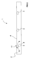
- FIG. 1 shows a plan view of a floor heating structure 1.
- the underfloor heating structure 1 comprises a carrier layer 2 which has a total of three grooves 3 in the present embodiment.
- Each groove 3 extends from the surface 4 of the carrier layer 2 shown in plan view into the carrier layer, which in the cross-sectional view of FIG FIG. 2 withdrawn can be.
- the grooves 3 are provided and designed such that they can accommodate a Temper michstechnisch 5, for example, a heating cable, which in an enlarged view of a groove 3 in FIG. 3 shown in detail.
- An inserted into the groove 3 Temper michs effet 5 is shown by dotted lines.
- the illustrated line course is purely exemplary in this case, the temperature control line 5 can also run straight or at least almost straight, but this is not mandatory.
- a small axial offset, for example, by about 2 mm may prove to be advantageous, since this may result in a better grip due to the pressure on the groove walls.
- Each groove 3 viewed in plan view, a wave or meandering course on what is FIG. 1 becomes clear. In longitudinal extension of the groove 3, this has, due to the wave or meander-like course, several successive groove sections 6 with mutually angled groove axes 7.
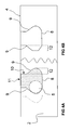
- FIG. 2 in synopsis with 4A Details of the cross-sectional shape of the groove 3 become clear.
- the groove 3 has a pear-shaped cross-section.
- the groove 3 comprises a groove bottom 8, adjoining side flanks 9, which open at the upper end of the groove 3 in a Nuthals 10, and located at the end of the Nuthalses 10 on the surface 4 groove opening 11.
- the Nuthalses 10 extend the Side edges 9 vertically downwards and are subsequently formed as an undercut 12.
- the undercut 12 has at the groove bottom 8 then a circular arc-like curved portion, which forms a kind of bulge. The bulge merges into an obliquely upward, continuously tapering towards Nuthals 10 section.
- the side edges 9 are thus formed in sections as an undercut 12, such that the groove 3 in a region between groove bottom. 8 and groove opening 11 in the direction of Nuthals 10 and the slot opening 11 towards continuously tapered.
- FIG. 3 shows an enlarged portion of the groove 3, in which the flexibly formed Temper michs effet 5 is inserted.
- the slot opening 11 is shown by solid lines, while the undercuts 12 are indicated by dotted lines.
- the wave-like course of the groove 3 causes the Temper michstechnisch 5 is pressed by self-generated by their restoring elasticity forces in certain sections of the groove 3 in the direction of the side edges 9.
- the tempering line 5 again by the elasticity forces, is pressed in the direction of the groove bottom 8.
- the Temperiansstechnisch 5 is thus pressed into the undercut 12 and towards the groove bottom 8, which is made 4A becomes clear.
- the position of the sections in which the temperature control line 5 is pressed against the side flanks 9 depends inter alia on the respective course of the groove 3.
- these sections have a negative radius of curvature with respect to the respective local slot axes 7, ie are concavely curved with respect to the respective local slot axes 7. Proceeding from this it should be mentioned that in principle it would be sufficient if the undercuts 12 were formed only on these concave sections.
- undercut 12 For example, an alternative form of undercut 12 is shown.
- the undercut 12 of the right side edge 9 corresponds to the shape of the reference to FIG. 2 and 4A described rounded undercut 12.
- the undercut 12 of the left side flank 9 is angular. From the juxtaposition in 4B It is clear that the alternative form is equally suitable and the same advantageous effects can be achieved. Same effects can be achieved with other groove sections, which are formed in their geometry with respect to the groove functionality described above. By way of example, dovetail-like or bottle-like groove cross-sections are mentioned.
- a groove cross-section with funnel-shaped or truncated cone-shaped undercut comes into consideration, wherein the large funnel opening or the large truncated cone base can end directly on the groove bottom or at a distance from the groove bottom. In the latter case, the remaining distance between the funnel or truncated cone-shaped course and the groove bottom can be bridged, for example by a vertical wall.
- the width of the groove opening 11 can be selected to be larger than the diameter of the Temper michstechnisch 5.
- a particularly simple insertion of the Temper michs effet 5 can be ensured in the groove 3, wherein in an advantageous manner can also be avoided that the Temper michs effet 5 is damaged when inserted into the groove 3.
- the latter can occur, for example, in grooves according to the prior art, in which for the purpose of holding the Temper michstechnisch 5 in the groove 3, the width of the groove opening is narrowed at predetermined locations or formed smaller than the diameter of Temper michstechnisch.
- the filler may generally be organic or inorganic materials, including organic and inorganic composite materials.
- the filling material has a stabilizing effect, provides additional support for the temperature control line 5 and also serves as protection for the Temper michstechnisch 5 against external influences. Furthermore, the filler allows a better heat transfer.
- grooves 3 extend between opposite sides of the carrier layer 2, wherein the coarse geometry of each groove 3 is substantially linear.
- the coarse geometry should be understood as the course of the groove 3 regardless of the fine geometric, in this case wave-like shape.
- Other rough geometries are conceivable.
- the rough geometry could, at least in sections, be given by a spiral-like course or by bays or loops.
- the rough geometry can also have sections with sinusoidal or cosinusoidal curve shapes or sections with curve shapes in the manner of a spline. These waveforms allow a fairly simple insertion of the temperature control 5.
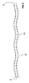
- a coarse geometry with bays is in a variant for underfloor heating construction in FIG. 5 shown.
- groove 3 has in its longitudinal extent a total of three, substantially mutually parallel first groove portions 13 with linear coarse geometry. These first groove regions 13 are connected to one another by curved second groove regions 14, so that the overall loop-shaped or book-like coarse geometry of the groove 3 results.
- the number of bays can vary from the representation in FIG. 5 deviate and according to the respective requirements, such.
- Coarse geometries are particularly suitable in which the transition from a curved groove region into a linear groove region is tangential, ie the linear groove region is comparable to a tangent at the circular radius of the curved groove region in the transition region.
- first groove portions 13 analogous to FIG. 1 .
- a plurality of successively located groove sections 6 are arranged, which are interconnected by transition sections 15.
- the groove sections 6 of FIG. 5 point in contrast to FIG. 1 not mutually angled, but with respect to the longitudinal extent of the groove 3 mutually offset groove axes 7.
- the side edges 9 of the groove 3 at least in the first groove portions 13 undercuts 12, which are formed according to the above embodiments.
- first groove portion 13 illustrates.
- the offset of the groove axes 7, corresponding to angled groove axes 7 in FIG. 1 results in a first opening width B1 available for introducing the tempering line 5 into the groove 3 being larger than a second opening width B2 available over the entire length of the first groove area 13.
- first opening width B1 is greater and the second opening width B2 is smaller than the diameter of the temperature control line 5, it can be achieved that the temperature control line 5 following the linear coarse geometry of the first groove area 13 can not emerge from the groove 3.
- a directed by the elasticity of the Temperiansstechnisch 5 in the direction of the groove bottom 8 force effect can be achieved with a suitable design of the groove 3.
- the groove 3 may for example have a depth of about 25 mm, and the width of the groove opening 11 may be about 19 mm.
- a maximum width in the region of the undercut 12 can be about 29 mm.
- the in 4A curved transition between groove bottom 8 and the tapered portion of the undercut 12 have a radius of curvature of about 7 mm; and a transition between the tapered portion and the groove neck 10 may have a radius of curvature of about 1 mm.
- the tapered portion of the undercut 12 may include an angle of approximately 55 degrees with the opening plane of the groove 3.
- a groove 3 designed in accordance with the dimension given above is equally suitable for tempering lines 5 with diameters in the range from 14 mm to 17 mm.
- the production of the groove 3 is therefore subject to less stringent requirements regarding dimensional tolerances. This simplifies the production and moreover leads to a cost reduction in the production of the groove 3.
- Suitable materials are all suitable for the production of a floor, wall or ceiling component suitable building materials, especially materials with good thermal conductivity, for example: curable building materials, such as concrete and screed, gypsum, especially gypsum fiber mixtures, anhydrite, wood, in particular Solid wood, chipboard, pulpwood, plywood, as well as plastic and / or hard foam.
- curable building materials such as concrete and screed, gypsum, especially gypsum fiber mixtures, anhydrite, wood, in particular Solid wood, chipboard, pulpwood, plywood, as well as plastic and / or hard foam.
- the groove 3 may be formed along with the manufacture of the floor, wall or ceiling component.
- prefabricated components eg. As installation panels and the like., Are provided, which can be installed on site and comparatively quickly equipped with Temper réelles effeten 5.
- the grooves 3 are formed on site side after preparation of the carrier layer 2.
- the carrier layer 2 can be constructed, for example, by tiling-like joining of carrier plates.
- the grooves 3 can either after construction of the entire carrier layer 2, d. H. after laying all required carrier plates, or successively for single or multiple carrier plates in the construction of the carrier layer 2 are formed. It is also possible to realize the invention in old screeds, by introducing the corresponding grooves in the old screeds.
- Milling methods are particularly suitable not only for the construction site-side shaping of the grooves 3, in which the grooves 3 are machined or manually machined with a milling device designed in the manner of a router into the carrier layer 2 or carrier plate.
- milling cutters in particular end mills, can be used, which are formed according to the dimensions of the groove 3, so that the grooves 3 can be formed, for example, in a single milling operation.
- An advantage of the site-side production of the grooves 3 is inter alia in the particularly high flexibility with regard to spontaneous changes or adjustments of the groove course.
- the milling device is guided starting from an end face of the carrier layer 2 or starting from a starting recess in the carrier layer 2 parallel to the surface 4 of the carrier layer 2, wherein the intended groove profile is generated by appropriately guiding the milling device.
- a corresponding sawtooth-like, wave-like, meandering and / or serrated groove profile is produced by sawtooth-like, wave-like, meandering and / or serrated guiding of the milling device.
Abstract
Description
Die Erfindung betrifft einen Flächentemperierungsaufbau mit einer Trägerschicht zum Halten einer Temperierungsleitung.The invention relates to a surface tempering structure with a carrier layer for holding a Temperierungsleitung.
Solche Flächentemperierungsaufbauten kommen beispielsweise bei Fußbodenheizungen zum Einsatz. Aus der
Einerseits wird vorgeschlagen, die Nut nach Einbringen der Temperierungsleitung in die Nut mit Spachtelmasse zu verfüllen. Zum besseren Halt der Spachtelmasse ist vorgesehen, dass die Nut in Nähe der Nutöffnung an sich gegenüberliegenden Seitenflanken Rillen aufweist, in welche die Spachtelmasse nach deren Aushärten eingreifen kann.On the one hand, it is proposed to fill the groove with putty after introducing the tempering line into the groove. For a better grip of the putty it is provided that the groove in the vicinity of the groove opening on opposite side edges has grooves into which the putty can intervene after curing.
Andererseits wird vorgeschlagen, die Nutöffnung an vorgegebenen Stellen entlang der Nut zu verengen, so dass der Durchmesser der Nutöffnung etwas kleiner ist als der Durchmesser der Temperierungsleitung. In diesem Fall wird die Temperierungsleitung an den verengten Stellen in die Nuten eingedrückt, wobei durch Rastwirkung ein Halt der Temperierungsleitung in der Nut erreicht wird.On the other hand, it is proposed to narrow the slot opening at predetermined locations along the groove, so that the diameter of the slot opening is slightly smaller than the diameter of the Temperierungsleitung. In this case, the Temperierungsleitung is pressed at the constricted points in the grooves, wherein a stop of the Temperierungsleitung is achieved in the groove by latching action.
Ein Nachteil des bekannten Bodenaufbaus ist, dass die Temperierungsleitungen durch Eindrücken in die Nut an den verengten Stellen beschädigt werden können. Ferner kann nicht sichergestellt werden, dass die Temperierungsleitungen auf den Nutboden gedrückt werden, was bei Verfüllung mit Spachtelmasse zu Hohlräumen unter der Temperierungsleitung führen kann. Die Hohlräume wiederum können bei hoher punktueller Belastung der Spachtelmasse, z. B. durch Stuhlrollenbelastungen, einbrechen, was zu Schäden an der Temperierungsleitung führen kann. Des Weiteren ist es erforderlich, dass die Nut mit hoher Maßgenauigkeit, d. h. geringen Toleranzen, hergestellt wird, damit ein zuverlässiger Halt der Temperierungsleitung sichergestellt werden kann. Das ist aufwändig, kosten- und arbeitsintensiv. Insbesondere mechanische Abnutzungen an Fräsern, welche z. B. zur Herstellung der Nuten verwendet werden, führen zu einer stetigen Verringerung des Nutdurchmessers, wodurch ein Einbringen der Temperierungsleitung in die Nut maßgeblich beeinträchtigt werden kann, und die Wahrscheinlichkeit zur Beschädigung der Temperierungsleitung zunimmt. Ein Austausch von abgenutzten Fräsern und deren Wiederaufbereitung ist aufwändig und kostenintensiv.A disadvantage of the known floor structure is that the Temperierungsleitungen can be damaged by pressing into the groove at the narrowed areas. Furthermore, it can not be ensured that the Temperierungsleitungen be pressed onto the groove bottom, which can lead to cavities under the Temperierungsleitung when filled with filler. The cavities in turn can at high point load of the filler, z. B. by Stuhlrollenbelastungen, break, which can lead to damage to the Temperierungsleitung. Furthermore, it is necessary that the groove with high dimensional accuracy, d. H. low tolerances, is manufactured, so that a reliable hold of Temperierungsleitung can be ensured. This is expensive, costly and labor intensive. In particular, mechanical wear on milling cutters, which z. B. used to produce the grooves, leading to a steady reduction in the groove diameter, whereby an introduction of the Temperierungsleitung can be significantly affected in the groove, and increases the likelihood of damaging the Temperierungsleitung. An exchange of worn milling cutters and their reprocessing is complex and costly.
Ausgehend davon liegt der vorliegenden Erfindung die Aufgabe zugrunde, einen Flächentemperierungsaufbau bereitzustellen, mit welchem die Nachteile nach dem Stand der Technik vermieden werden können. Insbesondere soll ein Flächentemperierungsaufbau bereitgestellt werden, mit welchem ein besonders einfacher und sicherer Halt der Temperierungsleitung möglich ist. Unter analoger Aufgabenstellung soll ferner ein Bauelement mit Flächentemperierungsaufbau bereit gestellt werden.Based on this, the object of the present invention is to provide a surface tempering structure with which the disadvantages of the prior art can be avoided. In particular, a surface tempering is to be provided with which a particularly simple and secure hold the Temperierungsleitung is possible. Under analogous task, a device with surface tempering is also to be provided.
Diese Aufgabe wird gelöst durch die Merkmale der Ansprüche 1 und 18. Ausgestaltungen der Erfindung ergeben sich aus den Ansprüchen 2 bis 17.This object is achieved by the features of
Gemäß einem ersten Aspekt der Erfindung ist ein Flächentemperierungsaufbau (oder: Flächenklimatisierungsaufbau, Flächentemperierungseinrichtung) vorgesehen, welcher eine Trägerschicht mit einer von dessen Oberfläche in die Trägerschicht hinein reichenden Nut aufweist. Die Nut dient zur Aufnahme einer Temperierungsleitung (alternative Bezeichnung: Temperaturmedienleitung oder Temperiermedienleitung, beispielsweise eine Heizmedien- und/oder Kühlmedienleitung) und weist mehrere direkt oder über Übergangsabschnitte aufeinander folgende Nutabschnitte mit zueinander versetzten und/oder abgewinkelten Nutachsen auf.According to a first aspect of the invention, there is provided a surface tempering structure (or: surface conditioning structure, surface temperature control device) which comprises a carrier layer with one of its surface in the carrier layer has in reaching groove. The groove serves to receive a temperature control line (alternative designation: temperature medium line or temperature control medium line, for example a heating medium and / or cooling medium line) and has a plurality of directly or via transition sections successive groove sections with mutually offset and / or angled groove axes.
Der Begriff Temperierung wird hierbei insbesondere derart umfassend verstanden, dass von der Flächentemperierung eine Heiz- oder Kühlwirkung ausgehen kann. Die Erfindung umfasst somit neben einem Flächenerwärmungsaufbau auch einen Flächenkühlungsaufbau sowie auch einen Aufbau, der sowohl eine Erwärmung als auch eine Kühlung bewirken kann, je nach eingesetztem Temperiermedium. Dementsprechend kann es sich bei der Temperierungsleitung um eine Heiz- und/oder Kühlmedienleitung handeln.In this case, the term temperature control is understood to be particularly comprehensive, such that a heating or cooling effect can emanate from the surface temperature control. Thus, in addition to a surface heating structure, the invention also encompasses a surface cooling structure as well as a structure which can bring about both heating and cooling, depending on the tempering medium used. Accordingly, the temperature control line can be a heating and / or cooling medium line.
Gemäß einer bevorzugten Ausbildung ist zum Halten der Temperierungsleitung zumindest eine Seitenflanke der Nut zumindest an vorgegebenen Stellen in den Nutabschnitten und/oder in den Übergangsabschnitten zwischen aufeinander folgenden Nutabschnitten zumindest abschnittsweise als Hinterschneidung ausgebildet. Dabei ist die Hinterschneidung derart ausgebildet, dass sich die Nut jeweils zumindest in einem Bereich zwischen Nutboden und Nutöffnung oder Nuthals zur Nutöffnung oder zum Nuthals hin kontinuierlich verjüngt.According to a preferred embodiment, at least one side edge of the groove is formed at least at predetermined locations in the groove sections and / or in the transition sections between successive groove sections at least in sections as an undercut for holding the tempering line. In this case, the undercut is formed such that the groove continuously tapers in each case at least in a region between groove bottom and groove opening or groove neck for slot opening or Nuthals out.
Die Temperierungsleitungen sind in der Regel elastisch bzw. biegsam ausgebildet. Durch den Versatz der Nutachsen bzw. durch die zueinander abgewinkelten Nutachsen wird bewirkt, dass die Temperierungsleitung nach Einbringen in die Nut durch die Hinterschneidung/en sicher gehalten wird. Bei gekrümmtem Verlauf der Temperierungsleitung in der Nut wird die Temperierungsleitung durch ihre eigene Elastizität, in einer Richtung parallel zur Trägerschicht an Seitenflanken der Nut gedrückt. Da sich die Nut zur Nutöffnung hin verjüngt, wird die Temperierungsleitung in Richtung des Nutbodens gedrückt. Dadurch kann bereits ohne Verfüllung der Nut mit Spachtelmasse und dgl. ein sicherer Halt der Temperierungsleitung in der Nut sichergestellt werden. Ferner ist es im Gegensatz zum Stand der Technik auch nicht erforderlich, dass an der Nutöffnung zusätzliche Mittel zum klemmenden Halten der Temperierungsleitung angebracht sind. Es können also durch Klemmen und dgl. verursachte Beschädigungen der Temperierungsleitung beim Einsetzen in die Nut vermieden werden.The Temperierungsleitungen are usually elastic or flexible. The offset of the groove axes or by the mutually angled groove axes causes the temperature control is held securely after insertion into the groove by the undercut / s. In the case of a curved course of the tempering line in the groove, the tempering line is pressed by its own elasticity in a direction parallel to the carrier layer on side flanks of the groove. Since the groove tapers towards the groove opening, the temperature control line is pressed in the direction of the groove bottom. This allows already without backfilling the groove with putty and the like. A secure hold the Temperierungsleitung be ensured in the groove. Furthermore, in contrast to the prior art, it is also not necessary that additional means for clamping holding the temperature control line be attached to the slot opening. It can therefore be avoided by terminals and the like. Damage caused Temperierungsleitung when inserting into the groove.
Werden die Seitenflanken zumindest an denjenigen Stellen hinterschnitten, an welchen die Temperierungsleitung infolge ihrer Elastizität an die Seitenflanke gedrückt wird, kann eine besonders vorteilhafte und einfache Halterung der Temperierungsleitung ohne weitere Sicherungsmaßnahmen sichergestellt werden.If the side edges are undercut at least at those points at which the Temperierungsleitung is pressed due to their elasticity to the side edge, a particularly advantageous and easy mounting of Temperierungsleitung be ensured without further security measures.
Bei geeigneter Ausbildung der Hinterschneidung kann sogar erreicht werden, dass die Temperierungsleitung stets auf den Nutboden gedrückt wird, so dass ein Aufschwemmen der Temperierungsleitung bei Verfüllen der Nut mit einem Füllmaterial vermieden wird. Damit wird der Entstehung von Hohlräumen unter der Temperierungsleitung entgegengewirkt.With a suitable design of the undercut can even be achieved that the Temperierungsleitung is always pressed onto the groove bottom, so that a Aufschwemmen the Temperierungsleitung is avoided when filling the groove with a filler. This counteracts the formation of cavities under the tempering line.
Der Flächentemperierungsaufbau kann Bestandteil einer in einen Fußboden, eine Wand und/oder eine Decke eines Bauwerks integrierten Flächentemperierung sein. Unter Temperierung wird dabei insbesondere verstanden, dass von der Flächentemperierung eine Heiz- oder Kühlwirkung ausgehen kann. Insoweit kann der Flächentemperierungsaufbau insbesondere Bestanteil einer Fußboden-, Wand- oder Deckenheizung sein. Je nach Verwendungszweck kann durch die Temperierungsleitung ein - verglichen mit der Umgebungstemperatur - wärmeres oder kälteres Temperaturmedium (oder: Temperiermedium, Wärmeträger, beispielsweise ein Heiz- und/oder Kühlmedium) geführt oder gepumpt werden. Der Flächentemperierungsaufbau eignet sich gleichermaßen für alle Boden-, Wand- und Deckenarten, insbesondere für Hohl- oder Doppelböden, -wände oder -decken.The surface tempering structure may be part of an integrated in a floor, a wall and / or a ceiling of a building surface temperature control. Tempering means in particular that a heating or cooling effect can emanate from the surface temperature control. In that regard, the surface tempering structure can be in particular Bestanteil a floor, wall or ceiling heating. Depending on the intended use, the temperature control line can be used to conduct or pump a warmer or colder temperature medium (or: tempering medium, heat transfer medium, for example a heating and / or cooling medium) compared to the ambient temperature. The surface tempering structure is equally suitable for all types of floor, wall and ceiling, in particular for hollow or raised floors, walls or ceilings.
Zur Stabilisierung und zum Schutz der Temperierungsleitung kann ein von der Temperierungsleitung nicht vereinnahmtes Volumen der Nut mit einem aushärtbaren Füllmaterial verfüllt sein. Damit eine weitgehend vollständige Füllung mit dem Füllmaterial erreicht werden kann, ist es von Vorteil, wenn das Füllmaterial fließfähig ist.To stabilize and protect the Temperierungsleitung a not occupied by the Temperierungsleitung volume of the groove may be filled with a curable filler. So that a substantially complete filling with the filling material can be achieved, it is advantageous if the filling material is flowable.
Mit der erfindungsgemäß ausgebildeten Nut kann erreicht werden, dass die Temperierungsleitung stets auf den Nutboden gedrückt wird. Demzufolge kann vermieden werden, dass sich nach dem Aushärten der Füllmasse Hohlräume ausbilden, welche der punktuellen Belastbarkeit abträglich sind. Unter Umständen ist zur Verfüllung der Nut auch ein entsprechend feinkörniges, vorzugsweise aushärtbares, Trockenfüllmaterial geeignet.With the groove formed according to the invention it can be achieved that the tempering line is always pressed onto the groove bottom. Consequently, it can be avoided that form cavities after curing of the filling material, which are detrimental to the punctual load capacity. Under certain circumstances, a correspondingly fine-grained, preferably curable, dry filler material is suitable for filling the groove.
Von besonderem Vorteil ist es, dass durch die sich zur Nutöffnung hin kontinuierlich verjüngende Nut die Temperierungsleitung im Wesentlichen unabhängig von dessen Durchmesser gleichermaßen in Richtung Nutboden gedrückt wird. Das hat insbesondere den Vorteil, dass zumindest die Breite der Nutöffnung größer sein kann als der Durchmesser der Temperierungsleitung. Die Nut kann daher mit vergleichsweise weiten Toleranzen hinsichtlich der Bemaßung der Nut hergestellt werden. Mechanische Abnutzungen an Fräswerkzeugen bei spanender Herstellung der Nut, was bei Systemen nach dem Stand der Technik zu Komplikationen führen kann, sind daher weit weniger gravierend.It is particularly advantageous that, due to the groove tapering continuously towards the groove opening, the temperature control line is pressed essentially in the direction of the groove bottom, essentially independently of its diameter. This has the particular advantage that at least the width of the slot opening can be greater than the diameter of the Temperierungsleitung. The groove can therefore be made with comparatively wide tolerances with regard to the dimensioning of the groove. Mechanical wear on milling tools during machining of the groove, which can lead to complications in prior art systems, are therefore far less serious.
Bei den erfindungsgemäß ausgebildeten Nuten ist es sogar möglich, dass - innerhalb gewisser Grenzen - dieselbe Nutform für Temperierungsleitungen mit unterschiedlichem Durchmesser gleichermaßen geeignet ist.In the case of the grooves designed according to the invention, it is even possible that-within certain limits-the same groove shape is equally suitable for tempering lines with different diameters.
Besonders bei spanender Herstellung der Nut mit einem Fräswerkzeug ist es von Vorteil, wenn beide Seitenflanken der Nut als Hinterschneidungen derart ausgebildet sind, dass sich die Nut zumindest in einem Bereich zwischen Nutboden und Nutöffnung in Richtung vom Nutboden zur Nutöffnung hin beidseitig kontinuierlich verjüngt. In diesem Fall kann die Nut mit einem einzigen Fräswerkzeug, z. B. mit einem Schaftfräser, und in einem Arbeitsgang hergestellt werden.Particularly when machining the groove with a milling tool, it is advantageous if both side edges of the groove are formed as undercuts such that the groove continuously tapers on both sides at least in a region between the groove bottom and groove opening in the direction from the groove bottom to the groove opening. In this case, the groove with a single milling tool, z. B. with an end mill, and are produced in one operation.
Hinsichtlich der konkreten Form der Nut, d. h. insbesondere hinsichtlich der zueinander versetzten und/oder abgewinkelten Nutachsen, gibt es mehrere im Wesentlichen gleichermaßen geeignete Formen. Beispielsweise kommen Ausgestaltungen in Betracht, bei welchen der Nutverlauf in einer Ebene parallel zur Trägerschicht sägezahnartig, wellenartig, mäanderartig und/oder zackenlinienartig ausgebildet ist. Für die Herstellung der Nuten mit einem Fräsverfahren eignen sich besonders wellenartige oder mäanderartige Nutverläufe, da solche Formen mit einem vergleichsweise niedrigen Aufwand in der Trägerschicht geformt werden können. Mit wellenartig bzw. mäanderartig gerundeten Formen können Querkanten in der Nut vermieden werden. Solche Querkanten können bei Andrücken der Temperierungsleitung an die Seitenflanken Beschädigungen, wie z. B. Knickungen, hervorrufen.With regard to the concrete shape of the groove, d. H. In particular with regard to mutually offset and / or angled groove axes, there are several substantially equally suitable forms. For example, embodiments come into consideration in which the Nutverlauf is formed in a plane parallel to the support layer sawtooth, wave-like, meandering and / or serrated. Particularly wave-like or meander-like groove courses are suitable for the production of the grooves with a milling method, since such shapes can be formed in the carrier layer with a comparatively low outlay. With wavy or meandering rounded shapes transverse edges can be avoided in the groove. Such transverse edges can damage when pressing the Temperierungsleitung to the side edges damage such. B. buckling cause.
Wenn die Nut mittels eines Fräsverfahrens und in einem Arbeitsgang hergestellt wird, werden beide Seitenflanken der Nut in der Regel entsprechend der erfindungsgemäßen Hinterschneidung ausgebildet sein. Es ist jedoch auch möglich, dass die Seitenflanken lediglich an denjenigen Abschnitten eine Hinterschneidung aufweisen, an welchen ein Verlauf der Seitenflanke bezüglich der Nutachse einen negativen Krümmungsradius bzw. negative Krümmungsradien aufweist. An solchen Stellen wird eine in die Nut eingelegte flexible Temperierungsleitung durch deren Elastizität in der Regel in Richtung Hinterschneidung gedrückt, wobei durch die spezielle Struktur der Hinterschneidung wiederum bewirkt wird, dass die Temperierungsleitung in Richtung Nutboden gedrückt wird.If the groove is produced by means of a milling process and in one operation, both side edges of the groove will generally be formed according to the undercut according to the invention. However, it is also possible for the side flanks to have an undercut only at those portions at which a profile of the side flank with respect to the groove axis has a negative radius of curvature or negative radii of curvature. At such points, inserted into the groove flexible Temperierungsleitung is pressed by the elasticity usually in the direction of undercut, which is in turn caused by the special structure of the undercut that the Temperierungsleitung is pressed in the direction Nutboden.
Die Grobgeometrie der Nut oder zumindest eines größeren zusammenhängenden Abschnitts der Nut kann verschiedenartige Ausprägungen aufweisen. Dabei wird unter Grobgeometrie der Verlauf der Nut ungeachtet der feingeometrischen Form der Nutabschnitte und Übergangsbereiche verstanden. Beispielsweise kann sich die Nut im Wesentlichen linear über die Trägerschicht erstrecken. In Frage kommen auch spiralartige Formen, und Formen mit einer oder mehreren Buchten bzw. Schleifen. Bei Ausgestaltungen mit linearer Grobgeometrie oder bei einer Grobgeometrie mit Buchten oder Schleifen kann die Nut in deren Längserstreckung mehrere, vorzugsweise parallel zueinander verlaufende, erste Nutbereiche aufweisen, in welchen jeweils mehrere Nutabschnitte und Übergangsabschnitte ausgebildet sind. Zur Ausbildung von Buchten bzw. Schleifen können diese ersten Nutbereiche durch gekrümmte zweite Nutbereiche miteinander verbunden sein. Ausgehend davon wird deutlich, dass die Grobgeometrie der Nut unter Aufrechterhaltung der vorteilhaften Wirkungen in weiten Grenzen variiert, und an jeweilige Erfordernisse, wie z. B. gewünschte Flächendichte der Temperierungsleitungen, angepasst werden kann.The coarse geometry of the groove or at least a larger contiguous portion of the groove may have various forms. In this case, coarse geometry is understood to mean the course of the groove, regardless of the fine geometric shape of the groove sections and transition regions. For example, the groove may be substantially linear over the carrier layer extend. In question are also spiral-like shapes, and forms with one or more bays or loops. In embodiments with linear coarse geometry or in a coarse geometry with bays or loops, the groove may have in the longitudinal extent thereof a plurality of, preferably mutually parallel, first groove regions, in each of which a plurality of groove sections and transition sections are formed. To form bays or loops, these first groove areas may be connected to one another by curved second groove areas. From this it is clear that the coarse geometry of the groove varies while maintaining the beneficial effects within wide limits, and to respective requirements, such. B. desired area density of Temperierungsleitungen, can be adjusted.
Die Trägerschicht kann aus einem beliebigen, zum Aufbau einer Trägerschicht für Boden-, Wand- oder Deckentemperierungsaufbauten geeigneten Material hergestellt sein. Insbesondere eignen sich aushärtbare Baustoffe, wie Beton, Estrich und dergleichen. Es kommen auch Materialien wie Gips, insbesondere Gips-Faser-Gemische, Anhydrit, Holz, insbesondere Vollholz, Spanholz, Faserholz, Schichtholz, sowie Kunststoffe und/oder Hartschaum in Betracht. Dabei kann die Trägerschicht eine oder mehrere aneinandergefügte oder zusammengefügte Trägerschichtplatten umfassen.The backing layer can be made of any material suitable for constructing a backing layer for floor, wall or ceiling tempering constructions. In particular, hardenable building materials, such as concrete, screed and the like are suitable. There are also materials such as gypsum, especially gypsum fiber mixtures, anhydrite, wood, especially solid wood, chipboard, pulpwood, plywood, and plastics and / or hard foam into consideration. In this case, the carrier layer may comprise one or more adjoined or joined carrier layer plates.
Ein zweiter Aspekt der Erfindung betrifft ein Bauelement, insbesondere ein Fertigbauelement, umfassend ein Boden,- Wand- oder Deckenbauelement mit einem Flächentemperierungsaufbau nach dem ersten Aspekt der Erfindung. Vorteile und vorteilhafte Wirkungen für den zweiten Aspekt der Erfindung ergeben sich aus den Vorteilen und vorteilhaften Wirkungen zum ersten Aspekt der Erfindung. Insbesondere kann erreicht werden, dass die Temperierungsleitung ohne weitere Maßnahmen sicher in der Nut gehalten wird. Diese Wirkung kann unter Berücksichtigung von Höhe und maximaler Breite der Nut gleichermaßen für Temperierungsleitungen unterschiedlichen Durchmessers erreicht werden. Die erfindungsgemäß vorgeschlagene Nut ist ferner tolerant gegenüber Nutversätzen am Übergang zwischen aneinander grenzenden Fertigbauelementen. Insoweit verringert sich der Positionierungsaufwand, wenn der Flächentemperierungsaufbau aus einzelnen Trägerplatten zusammengesetzt wird.A second aspect of the invention relates to a component, in particular a prefabricated component, comprising a floor, wall or ceiling component with a surface temperature control structure according to the first aspect of the invention. Advantages and advantageous effects for the second aspect of the invention will be apparent from the advantages and advantageous effects of the first aspect of the invention. In particular, it can be achieved that the Temperierungsleitung is securely held in the groove without further action. Taking into account the height and maximum width of the groove, this effect can be achieved equally for temperature control lines of different diameters. The inventively proposed groove is also tolerant to groove offsets at the transition between each other adjacent prefabricated building elements. In that regard, reduces the positioning effort when the surface temperature control structure is composed of individual support plates.
Die Erfindung wird nachstehend anhand der Beschreibung von Ausführungsbeispielen und unter Bezugnahme auf die beiliegenden Zeichnungen näher erläutert. Es zeigen:
- FIG 1
- eine Aufsicht auf einen Fußbodenheizungsaufbau als Beispiel eines erfindungsgemäßen Flächentemperierungsaufbaus,
- FIG 2
- einen Querschnitt durch den Fußbodenheizungsaufbau der
FIG 1 , - FIG 3
- eine Aufsicht auf einen vergrößerten Abschnitt einer Nut des Fußbodenheizungsaufbaus der
FIG 1 , - FIG 4A, 4B
- weitere Querschnitte des Fußbodenheizungsaufbaus, und
- FIG 5
- eine Aufsicht auf eine Variante des Fußbodenheizungsaufbaus.
- FIG. 1
- a plan view of a floor heating structure as an example of a surface temperature control structure according to the invention,
- FIG. 2
- a cross section through the underfloor heating structure of
FIG. 1 . - FIG. 3
- a plan view of an enlarged portion of a groove of the underfloor heating structure of
FIG. 1 . - 4A, 4B
- further cross sections of the floor heating system, and
- FIG. 5
- a view of a variant of the underfloor heating system.
Gleiche oder funktionsgleiche Elemente sind in den Figuren mit gleichen Bezugszeichen bezeichnet. Im Folgenden wird die Erfindung anhand eines Fußbodenheizungsaufbaus erläutert. Es wird bemerkt, dass die folgende Beschreibung ohne Weiteres auf andere Flächentemperierungsaufbauten übertragen werden kann, wie beispielsweise Wand- oder Deckentemperierungsaufbauten, insbesondere Wand- oder Deckenheizungsaufbauten.Identical or functionally identical elements are denoted by the same reference numerals in the figures. In the following, the invention will be explained with reference to a floor heating structure. It will be understood that the following description may be readily applied to other surface control structures, such as wall or ceiling temperature control assemblies, particularly wall or ceiling heater assemblies.
Jede Nut 3 weist, in Aufsicht betrachtet, einen wellen- bzw. mäanderartigen Verlauf auf, was aus
Aus
Die Seitenflanken 9 sind also abschnittsweise als Hinterschneidung 12 ausgebildet, derart dass sich die Nut 3 in einem Bereich zwischen Nutboden 8 und Nutöffnung 11 in Richtung zum Nuthals 10 bzw. zur Nutöffnung 11 hin kontinuierlich verjüngt.The side edges 9 are thus formed in sections as an undercut 12, such that the
Mittels der auf diese Weise ausgebildeten Nut 3 kann die Temperierungsleitung 5 sicher und ohne weitere Vorkehrungen in der Nut gehalten werden, was im Folgenden anhand von
Die Lage der Abschnitte, in welchen die Temperierungsleitung 5 an die Seitenflanken 9 gedrückt wird, hängt unter anderem vom jeweiligen Verlauf der Nut 3 ab. Im vorliegenden Ausführungsbeispiel weisen diese Abschnitte bezüglich der jeweiligen lokalen Nutachsen 7 einen negativen Krümmungsradius auf, sind also bezüglich der jeweiligen lokalen Nutachsen 7 konkav gekrümmt. Ausgehend davon sei erwähnt, dass es im Prinzip genügen würde, wenn die Hinterschneidungen 12 lediglich an diesen konkaven Abschnitten ausgebildet wären.The position of the sections in which the
In
Dadurch, dass die Temperierungsleitung 5 ohne weitere Maßnahmen sicher in der Nut gehalten wird, kann die Breite der Nutöffnung 11 größer gewählt werden als der Durchmesser der Temperierungsleitung 5. Auf diese Weise kann ein besonders einfaches Einlegen der Temperierungsleitung 5 in die Nut 3 gewährleistet werden, wobei in vorteilhafter Weise zudem vermieden werden kann, dass die Temperierungsleitung 5 beim Einsetzen in die Nut 3 beschädigt wird. Letzteres kann beispielsweise bei Nuten nach dem Stand der Technik auftreten, bei welchen zum Zwecke der Halterung der Temperierungsleitung 5 in der Nut 3 die Breite der Nutöffnung an vorgegebenen Stellen verengt ist bzw. kleiner ausgebildet ist als der Durchmesser der Temperierungsleitung.Characterized in that the
Wie in
Die in
Eine Grobgeometrie mit Buchten ist in einer Variante für den Fußbodenheizungsaufbau in
In den ersten Nutbereichen 13 sind, analog zu
Bei der vorliegenden Variante kann durch den Versatz der Nutachsen 7 ein sicherer Halt der Temperierungsleitung in der Nut 3 gewährleistet werden. Dabei ist es bei geeigneter Ausgestaltung des Nutquerschnitts möglich, dass der gleiche Effekt erzielt wird wie bei den abgewinkelten Nutachsen 7 der
Es wird darauf hingewiesen, dass auch Mischformen der beiden dargestellten Varianten, d. h. Mischformen von versetzten und abgewinkelten Nutachsen 7 im Rahmen der Erfindung liegen.It should be noted that mixed forms of the two variants shown, d. H. Mixed forms of staggered and
Mit Bezug zu
Für Durchmesser der Temperierungsleitung 5 im Bereich von 10 mm bis 20 mm, insbesondere 14 mm bis 17 mm, kann die Nut 3 beispielsweise eine Tiefe von ca. 25 mm aufweisen, und die Breite der Nutöffnung 11 kann ca. 19 mm betragen. Für den Fall, dass beide Seitenflanken 9 eine Hinterschneidung 12 aufweisen, kann eine im Bereich der Hinterschneidung 12 gelegene maximale Breite etwa 29 mm betragen. Dabei kann der in
Für die Herstellung der Nut 3 gibt es mehrere Möglichkeiten, welche unter anderem von dem Material abhängig sind, aus welchem die Trägerschicht 2 hergestellt ist. Als Materialien kommen alle zur Herstellung eines Boden-, Wand- oder Deckenbauelements geeigneten Baustoffe in Betracht, insbesondere Stoffe mit einer guten Wärmeleitfähigkeit, beispielsweise: aushärtbare Baustoffe, wie Beton und Estrich, Gips, insbesondere Gips-Faser-Gemische, Anhydrit, Holz, insbesondere Vollholz, Spanholz, Faserholz, Schichtholz, sowie Kunststoff und/oder Hartschaum.For the production of the
Die Nut 3 kann einhergehend mit der Herstellung des Boden-, Wand- oder Deckenbauelements geformt werden. Auf diese Weise können Fertigbauelemente, z. B. Verlegeplatten und dgl., bereitgestellt werden, welche Baustellenseitig verlegt und vergleichsweise zügig mit Temperierungsleitungen 5 bestückt werden können.The
Es ist aber auch möglich, dass die Nuten 3 baustellenseitig nach Herstellung der Trägerschicht 2 geformt werden. Dabei kann die Trägerschicht 2 beispielsweise durch kachelartiges Aneinanderfügen von Trägerplatten aufgebaut werden. Die Nuten 3 können entweder nach Aufbau der gesamten Trägerschicht 2, d. h. nach Verlegen aller erforderlichen Trägerplatten, oder sukzessive für einzelne oder mehrere Trägerplatten beim Aufbau der Trägerschicht 2 geformt werden. Es ist auch möglich, die Erfindung in alten Estrichen zu verwirklichen, durch Einbringung der entsprechenden Nuten in die alten Estriche.But it is also possible that the
Nicht nur für die baustellenseitige Formung der Nuten 3 eignen sich insbesondere Fräsverfahren, bei welchen die Nuten 3 mit einer nach Art einer Oberfräse ausgebildeten Fräseinrichtung in die Trägerschicht 2 bzw. Trägerplatte automatisiert oder manuell gefräst werden. Bei den Fräsverfahren können Fräser, insbesondere Schaftfräser, verwendet werden, welche entsprechend den Bemaßungen der Nut 3 ausgebildet sind, so dass die Nuten 3 beispielsweise in einem einzigen Fräsgang geformt werden können. Ein Vorteil der baustellenseitigen Herstellung der Nuten 3 liegt unter anderem in der besonders hohen Flexibilität hinsichtlich spontaner Änderungen oder Anpassungen des Nutverlaufs. Zur Ausbildung der Nut wird die Fräseinrichtung ausgehend von einer Stirnseite der Trägerschicht 2 oder ausgehend von einer Startvertiefung in der Trägerschicht 2 parallel zur Oberfläche 4 der Trägerschicht 2 geführt, wobei durch entsprechendes Führen der Fräseinrichtung der vorgesehene Nutverlauf erzeugt wird. Beispielsweise wird durch sägezahnartiges, wellenartiges, mäanderartiges und/oder zackenlinienartiges Führen der Fräseinrichtung ein entsprechender sägezahnartiger, wellenartiger, mäanderartiger und/oder zackenlinienartiger Nutverlauf erzeugt.Milling methods are particularly suitable not only for the construction site-side shaping of the
Wenn Rohre von unten in bzw. aus der Trägerschicht oder dem gesamten Bauelement geführt werden sollen, kann zur Verwirklichung der Fräser bei der Nutherstellung derart geführt werden, dass er abtaucht und gleichzeitig die Grobgeometrie, beispielsweise eine Wellenform, weiterfräst. Die dadurch gebildete Nut verhindert, dass die Temperierungsleitung auf der Oberseite der Trägerschicht bzw. des Bauelements aus der Nut aufsteigt. Als vorteilhaft erweist sich hierbei die Ausbildung einer 180°-Spirale beim Abtauchen des Fräsers.If pipes are to be guided from below into or out of the carrier layer or the entire component, it is possible for the purpose of realizing the milling cutter to be guided during groove production in such a way that it dips and at the same time continues to mill the rough geometry, for example a wave shape. The groove formed thereby prevents the Temperierungsleitung rises on the top of the carrier layer or the component of the groove. It proves to be advantageous in this case the formation of a 180 ° spiral during the descent of the milling cutter.
Insbesondere aus der Beschreibung der Ausführungsbeispiele wird deutlich, dass mit dem erfindungsgemäßen Flächentemperierungsaufbau eine besonders einfache und sichere Halterung der Temperierungsleitung möglich ist. Ferner kann bei vergleichsweise geringen Herstellungskosten eine schnelle und dennoch qualitativ hochwertige Verlegung der Temperierungsleitungen erreicht werden. In vorteilhafter Weise kann insbesondere vermieden werden, dass die Temperierungsleitung beim Einbringen in die Nuten beschädigt wird.In particular, from the description of the embodiments it is clear that with the surface temperature control structure according to the invention a particularly simple and secure mounting of the temperature control is possible. Furthermore, with relatively low production costs, a fast, yet high-quality installation of the temperature control lines can be achieved. In an advantageous manner, it can be avoided, in particular, that the tempering line is damaged when it is introduced into the grooves.
- 11
- Fußbodenheizungsaufbaufloor heating setup
- 22
- Trägerschichtbacking
- 33
- Nutgroove
- 44
- Oberflächesurface
- 55
- TemperierungsleitungTemperierungsleitung
- 66
- Nutabschnittgroove
- 77
- Nutachsegroove axis
- 88th
- Nutbodengroove bottom
- 99
- Seitenflankeside flank
- 1010
- Nuthalsslot neck
- 1111
- Nutöffnungslot opening
- 1212
- Hinterschneidungundercut
- 1313
- erster Nutbereichfirst groove area
- 1414
- zweiter Nutbereichsecond groove area
- 1515
- ÜbergangsabschnittTransition section
- B1B1
- erste Öffnungsbreitefirst opening width
- B2B2
- zweite Öffnungsbreitesecond opening width
Claims (15)
Applications Claiming Priority (1)
| Application Number | Priority Date | Filing Date | Title |
|---|---|---|---|
| DE202008004383U DE202008004383U1 (en) | 2008-03-28 | 2008-03-28 | Flächentemperierungsaufbau |
Publications (2)
| Publication Number | Publication Date |
|---|---|
| EP2105675A2 true EP2105675A2 (en) | 2009-09-30 |
| EP2105675A3 EP2105675A3 (en) | 2014-04-16 |
Family
ID=40586231
Family Applications (1)
| Application Number | Title | Priority Date | Filing Date |
|---|---|---|---|
| EP09003194.9A Withdrawn EP2105675A3 (en) | 2008-03-28 | 2009-03-05 | Surface tempering structure |
Country Status (3)
| Country | Link |
|---|---|
| EP (1) | EP2105675A3 (en) |
| DE (1) | DE202008004383U1 (en) |
| RU (1) | RU2400602C1 (en) |
Cited By (1)
| Publication number | Priority date | Publication date | Assignee | Title |
|---|---|---|---|---|
| DE102014110843A1 (en) | 2014-05-13 | 2015-11-19 | Jaeger Floor Systems GmbH + Co KG | Surface tempering element and from several surface temperature control elements existing surface tempering |
Families Citing this family (4)
| Publication number | Priority date | Publication date | Assignee | Title |
|---|---|---|---|---|
| DE102011054069A1 (en) * | 2011-09-29 | 2013-04-04 | Entsorgungstechnik Kraus Martin E.K. | Method for producing large-area floor heating and floor heating produced by this method |
| DE202014104621U1 (en) * | 2014-09-26 | 2016-01-05 | Uponor Innovation Ab | Flächentemperiersystem |
| GB2564855A (en) * | 2017-07-21 | 2019-01-30 | Timoleon Ltd | Surface heat-transfer apparatus |
| DE102017117196A1 (en) * | 2017-07-28 | 2019-01-31 | Josef Sieberer | Flächentemperierelement |
Citations (1)
| Publication number | Priority date | Publication date | Assignee | Title |
|---|---|---|---|---|
| DE202005002322U1 (en) | 2005-02-14 | 2005-04-07 | Lindner Ag | Base structure for underfloor heating comprises plates placed on supports with each plate having grooves for heating lines |
Family Cites Families (4)
| Publication number | Priority date | Publication date | Assignee | Title |
|---|---|---|---|---|
| DE3027430A1 (en) * | 1980-07-19 | 1982-02-25 | Kabel- und Metallwerke Gutehoffnungshütte AG, 3000 Hannover | PANEL HEATING |
| NO814027L (en) * | 1981-11-26 | 1983-05-27 | Rolf Jacobsen | FLOOR ELEMENT FOR MAKING A HEATED FLOOR COVER |
| ITTV20030079A1 (en) * | 2003-05-22 | 2004-11-23 | R D Z S P A | PANEL STRUCTURE FOR AIR CONDITIONING OF ENVIRONMENTS. |
| AT502704B1 (en) * | 2005-09-12 | 2008-07-15 | Johann Knapp | WALL OR CEILING CONSTRUCTION IN DRY CONSTRUCTION |
-
2008
- 2008-03-28 DE DE202008004383U patent/DE202008004383U1/en not_active Expired - Lifetime
-
2009
- 2009-02-13 RU RU2009105239/03A patent/RU2400602C1/en active
- 2009-03-05 EP EP09003194.9A patent/EP2105675A3/en not_active Withdrawn
Patent Citations (1)
| Publication number | Priority date | Publication date | Assignee | Title |
|---|---|---|---|---|
| DE202005002322U1 (en) | 2005-02-14 | 2005-04-07 | Lindner Ag | Base structure for underfloor heating comprises plates placed on supports with each plate having grooves for heating lines |
Cited By (2)
| Publication number | Priority date | Publication date | Assignee | Title |
|---|---|---|---|---|
| DE102014110843A1 (en) | 2014-05-13 | 2015-11-19 | Jaeger Floor Systems GmbH + Co KG | Surface tempering element and from several surface temperature control elements existing surface tempering |
| DE102014110843B4 (en) | 2014-05-13 | 2023-06-22 | Martin Knopp | Surface temperature control element and surface temperature control structure consisting of several surface temperature control elements |
Also Published As
| Publication number | Publication date |
|---|---|
| EP2105675A3 (en) | 2014-04-16 |
| RU2400602C1 (en) | 2010-09-27 |
| DE202008004383U1 (en) | 2009-04-30 |
Similar Documents
| Publication | Publication Date | Title |
|---|---|---|
| EP2226447B1 (en) | Panelling, in particular floor panelling | |
| EP1902186B1 (en) | Connecting device | |
| EP1294995A1 (en) | Floor covering plate | |
| EP2057327A1 (en) | Panel, especially floor panel | |
| EP2813783A1 (en) | Stand for supporting solar panels on a flat roof | |
| EP2105675A2 (en) | Surface tempering structure | |
| EP2989403B1 (en) | Composite system of refractory ceramic stones | |
| DE102008051441A1 (en) | Panel element for producing external area e.g. terrace floor, has set of connection profiles, where contour of one of connection profiles corresponds to contour of other connection profile after rotation of element around specific degree | |
| WO2002059423A1 (en) | Hexagonal floor covering element consisting of artificial stone | |
| EP3385462B1 (en) | Thermally insulating component | |
| EP2014843A2 (en) | Building brick with insulating material | |
| DE102006002910A1 (en) | Assembly plate used in the production of a corner element for heating pipes and cables comprises a wedge which is lower than the depth of the groove | |
| EP2816168B1 (en) | Cladding stone for connection with a concrete ceiling | |
| EP3580406B1 (en) | Decoupling track | |
| DE202020102526U1 (en) | Multi-profile panel | |
| DE19637379A1 (en) | Method for manufacturing construction elements e.g. wall or slab sections from press board panels | |
| EP1811099A2 (en) | Building element for making a corner element | |
| DE102005007949B4 (en) | Device for laying panels | |
| AT412794B (en) | INSULATION DEVICE, METHOD FOR FITTING PROFILE SIDES WITH FILLING BODIES, DEVICE FOR EXECUTING THE METHOD, AND METHOD FOR PRODUCING AN INSULATION DEVICE | |
| EP4283064B1 (en) | Method for embedding and fixing anchor rails in a building | |
| DE202018100602U1 (en) | An element | |
| EP2388407B1 (en) | Mounting wedge | |
| EP1873327B1 (en) | Method for laying tiles seamlessly | |
| EP2606189B1 (en) | Insulating element | |
| EP3907346A1 (en) | Multi-profile panel |
Legal Events
| Date | Code | Title | Description |
|---|---|---|---|
| PUAI | Public reference made under article 153(3) epc to a published international application that has entered the european phase |
Free format text: ORIGINAL CODE: 0009012 |
|
| AK | Designated contracting states |
Kind code of ref document: A2 Designated state(s): AT BE BG CH CY CZ DE DK EE ES FI FR GB GR HR HU IE IS IT LI LT LU LV MC MK MT NL NO PL PT RO SE SI SK TR |
|
| AX | Request for extension of the european patent |
Extension state: AL BA RS |
|
| PUAL | Search report despatched |
Free format text: ORIGINAL CODE: 0009013 |
|
| AK | Designated contracting states |
Kind code of ref document: A3 Designated state(s): AT BE BG CH CY CZ DE DK EE ES FI FR GB GR HR HU IE IS IT LI LT LU LV MC MK MT NL NO PL PT RO SE SI SK TR |
|
| AX | Request for extension of the european patent |
Extension state: AL BA RS |
|
| RIC1 | Information provided on ipc code assigned before grant |
Ipc: F24D 3/14 20060101AFI20140312BHEP |
|
| STAA | Information on the status of an ep patent application or granted ep patent |
Free format text: STATUS: THE APPLICATION HAS BEEN WITHDRAWN |
|
| 18W | Application withdrawn |
Effective date: 20140410 |