EP2103401B1 - Installation for the manufacture of ceramic products. - Google Patents
Installation for the manufacture of ceramic products. Download PDFInfo
- Publication number
- EP2103401B1 EP2103401B1 EP09154483.3A EP09154483A EP2103401B1 EP 2103401 B1 EP2103401 B1 EP 2103401B1 EP 09154483 A EP09154483 A EP 09154483A EP 2103401 B1 EP2103401 B1 EP 2103401B1
- Authority
- EP
- European Patent Office
- Prior art keywords
- mould
- outside surface
- installation according
- fluid
- rear outside
- Prior art date
- Legal status (The legal status is an assumption and is not a legal conclusion. Google has not performed a legal analysis and makes no representation as to the accuracy of the status listed.)
- Active
Links
Images


Classifications
-
- B—PERFORMING OPERATIONS; TRANSPORTING
- B28—WORKING CEMENT, CLAY, OR STONE
- B28B—SHAPING CLAY OR OTHER CERAMIC COMPOSITIONS; SHAPING SLAG; SHAPING MIXTURES CONTAINING CEMENTITIOUS MATERIAL, e.g. PLASTER
- B28B1/00—Producing shaped prefabricated articles from the material
- B28B1/26—Producing shaped prefabricated articles from the material by slip-casting, i.e. by casting a suspension or dispersion of the material in a liquid-absorbent or porous mould, the liquid being allowed to soak into or pass through the walls of the mould; Moulds therefor ; specially for manufacturing articles starting from a ceramic slip; Moulds therefor
- B28B1/265—Producing shaped prefabricated articles from the material by slip-casting, i.e. by casting a suspension or dispersion of the material in a liquid-absorbent or porous mould, the liquid being allowed to soak into or pass through the walls of the mould; Moulds therefor ; specially for manufacturing articles starting from a ceramic slip; Moulds therefor pressure being applied on the slip in the filled mould or on the moulded article in the mould, e.g. pneumatically, by compressing slip in a closed mould
- B28B1/266—Means for counteracting the pressure being applied on the slip or on the moulded article in the mould, e.g. means for clamping the moulds parts together in a frame-like structure
-
- B—PERFORMING OPERATIONS; TRANSPORTING
- B28—WORKING CEMENT, CLAY, OR STONE
- B28B—SHAPING CLAY OR OTHER CERAMIC COMPOSITIONS; SHAPING SLAG; SHAPING MIXTURES CONTAINING CEMENTITIOUS MATERIAL, e.g. PLASTER
- B28B1/00—Producing shaped prefabricated articles from the material
- B28B1/26—Producing shaped prefabricated articles from the material by slip-casting, i.e. by casting a suspension or dispersion of the material in a liquid-absorbent or porous mould, the liquid being allowed to soak into or pass through the walls of the mould; Moulds therefor ; specially for manufacturing articles starting from a ceramic slip; Moulds therefor
- B28B1/261—Moulds therefor
- B28B1/262—Mould materials; Manufacture of moulds or parts thereof
- B28B1/264—Plaster
-
- B—PERFORMING OPERATIONS; TRANSPORTING
- B28—WORKING CEMENT, CLAY, OR STONE
- B28B—SHAPING CLAY OR OTHER CERAMIC COMPOSITIONS; SHAPING SLAG; SHAPING MIXTURES CONTAINING CEMENTITIOUS MATERIAL, e.g. PLASTER
- B28B17/00—Details of, or accessories for, apparatus for shaping the material; Auxiliary measures taken in connection with such shaping
- B28B17/0063—Control arrangements
- B28B17/0081—Process control
Definitions
- This invention relates to an installation for the manufacture of ceramic products, in particular for the manufacture of ceramic sanitaryware.
- ceramic sanitaryware such as washbasins, toilet bowls, bidets, shower trays and the like
- a fluid mixture known as "slip" in the jargon of the trade, consisting of a ceramic body in aqueous suspension
- customary moulds with a porous structure, made in particular from resins.
- porous moulds are composed of at least two parts (usually known as “male” and “female” in the jargon of the trade) which are joined to form an internal cavity where the ceramic product is formed.
- porous surfaces that form the sides of each cavity will hereinafter be referred to as the inside surfaces of the mould.
- Each mould part also comprises a rear outside surface or back, on which the forces necessary to keep the two parts together during the casting cycle are exerted, and a lateral outside surface.
- At least one of the two outside surfaces is associated with auxiliary elements designed to support and keep the mould in place within the installation.
- contact surfaces which generally act as transitions between the lateral outside surfaces and the closing surfaces.
- these porous moulds are provided with a drainage system designed to allow the fluids that go through the inside surfaces to be channelled to the outside, or to pump fluids in under pressure in the opposite direction in order to detach the moulded product from the mould walls or to recondition the mould part.
- the two or more parts of the mould are mounted in suitable installations (that differ according to the type of product to be cast) and comprising at least the following:
- porous resin moulds are their good mechanical strength which allows them to be used for high pressure casting, that is to say, for pumping the slip into the mould and subsequently forming the cast wall thickness at high pressure (usually between 3 and 15 bar).
- the directions adopted by the force components are not only the direction in which the mould parts are moved together and clamped shut but also the directions at right angles (and hence transversal) to the mould part clamping direction.
- the above mentioned casting installations may (in one prior art solution) comprises a fixed abutment wall operating on the back of one of the mould parts, and a drive cylinder that operates on a mobile wall which in turn operates on the back of the other part of the mould.
- the cylinder may apply on the mobile part of the mould force that is constant or variable instant by instant as a function of slip pressure (known in the jargon of the trade as “ proportional clamping").
- proportional clamping a function of slip pressure
- the relative movements of the mould parts towards each other during the casting cycle may be either free and, hence, determined only by the balance of the forces in play and by the deformability characteristics of the resins, or limited to a maximum value thanks to the presence of mechanical stops which absorb the force applied by the piston in excess of the force sufficient to determine the maximum acceptable deformation (known in the jargon of the trade as "controlled deformation clamping").
- prior art solutions include purely passive mechanical systems that can preload the resin to varying extents with initial compression stresses along said transversal directions and whose reaction to the forces produced inside the cavity during the casting cycle and tending to compress the mould walls and to deform the lateral outside surface towards the containment device depends only on the rigidity of the containment device itself, or active mechanical systems where the reaction of the containment device is controlled over time and as a function, instant by instant, of slip pressure.
- the Applicant has devised and produced a device for "containing" the forces (see also patent EP 1.043.132 ) where one of the half-parts of the mould comprises a frame that delimits a space, between the frame and the half-part, for housing an element expandable by a fluid from the outside and designed to contain the forces generated by the pressure of the slip inside the mould.
- This system regulates the pressure of the fluid inside the expandable element, which is correlated constantly with slip pressure, obtaining an improved reaction, eliminating the potential deformation of the mould which leads to undesirable stress on the part being cast and, hence, to possible defects, and controlling elastic contractions of the mould.
- the solution involving a proportional force of the clamping cylinder is calibrated in such a way as to apply to all the parts of the mould the same pressure as that applied by the slip.
- the hydraulic system which acts on a flat part which is rigid by its very nature is a system with limited opposing precision, that is to say, with relatively wide tolerances compared to the requirements of the mould and with a considerably lower precision than that of the fluid system for the other components, which adapts the movements of the abutment surface opposing the lateral outside surface of the mould to the compressibility requirements of the resin layer below.
- This invention therefore has for an aim to provide an installation where the mould is subjected to a precisely determined pressure at all points of its outside surface and always correlated with the pressure inside the mould during the casting cycle. Accordingly, this invention achieves this aim by providing an installation for the manufacture of ceramic products, in particular for the manufacture of ceramic sanitaryware and comprising the technical characteristics set out in one or more of the appended claims.
- the installation according to the invention is used for manufacturing ceramic products, in particular but not limited to, ceramic sanitaryware (such as, for example, washbasins, toilet bowls, bidets, shower trays, and the like).
- ceramic sanitaryware such as, for example, washbasins, toilet bowls, bidets, shower trays, and the like.
- This installation labelled 100 in its entirety, comprises a mould 1 divided into at least two parts 2 and 3, forming an internal cavity C where the ceramic product is formed.
- each part 2 and 3 of the mould 1 is composed of a body delimited by: an outside surface comprising a rear surface 2p and 3p and a lateral surface 2s and 3s, and a working surface comprising an inside surface 2c and 3c wet by a casting liquid and defining the cavity C, and a front contact surface 2f and 3f which abuts the respective contact surface 3f and 2f of the other part 3 and 2 of the mould 1 when the two parts 3 and 2 of the mould 1 are closed (for the respective references, see also Figures 6 and 7 ).
- the body delimited by these surfaces is mostly composed, by way of non-limiting example, by one or more volumes of permeable or porous materials stably connected to each other.
- the two parts 2 and 3 can move towards and away from each other, under the action of respective drive means 4 acting in both directions along a predetermined clamping line S (see arrows in Figures 1 and 2 ), in such a way as to join or detach the two parts 2 and 3 to/from each other.
- the product casting liquid (slip in the case of ceramic products) is fed into the cavity C in order to cast the product.
- first feed means 10 At pressures P that differ according to the product casting cycle (the first feed means 10 being described in more detail below).
- the drive means 4 are in the form of a cylinder for moving the part 2 which is in turn supported by a crossbar T, but this embodiment must be considered as a non-limiting example of how to implement the invention, since the means 4 may be embodied by other floor or overhead rail or guide systems for both single-mould and multiple mould installations, without thereby departing from the scope of the invention.
- At least one of the parts - the one labelled 2 in this non-limiting example - is equipped with means 6 for containing a fluid and encompassing at least the above mentioned rear and lateral outside surfaces 2p and 2s of the mould 1 part 2 itself; these containment means 6 are associated with the part 2 in such a way that during the product casting cycle the fluid constantly applies reaction forces FR to compensate the forces SF acting on the part 2 of the mould 1, in the directions defined by the shape of the inside surface 2c of the mould part 2.
- these containment and control means 6 are interposed, in use, between the mould part 2 and the drive means 4.
- Figure 2 also shows that the other mould part 3 may also be equipped with containment and control means 6' acting on the rear and lateral outside surfaces 3p and 3s of the mould part 3.
- the part of the mould labelled 2 known in the jargon of the trade as the female part, will be considered.
- the containment and control means 6 comprise a sealed containment element 7 associated with the mould part 2 and surrounding the rear outside surface 2p and the lateral outside surface 2s of the mould part 2 itself.
- the containment element 7 is equipped with means 8 for pumping compensation fluid in and out of at least one compensation chamber 9 defined between the containment element 7 itself and the rear and lateral outside surfaces 2p and 2s of the mould part 2.
- the means 8 for pumping compensation fluid in and out of the compensation chamber 9 are correlated with the aforementioned means 10 for controlling the fluids in the cavity C: thus, in the chamber 9, the pressures P present in the moulding cavity C can be compensated in real time with a suitable pressure P' in the compensation chamber 9.
- At least the outside surface 2p of the mould part 2 has a protective jacket 11 or 12 (that might be, without limiting the invention, of the laminated type), sealed and shaped to match the profile of the rear outside surface 2p of the part 2 (see also Figure 7 ) and creating a separating surface between the compensation chamber 9 and the rear outside surface 2p itself, or the thickness of the permeable material constituting the body of the mould part 2.
- a protective jacket 11 or 12 that might be, without limiting the invention, of the laminated type
- This structural combination makes it possible to choose from different structural solutions, meaning geometrical shapes, of the mould part contained within the compensation chamber 9, without affecting the quality of the end product.
- the shape of the mould part 2 shown in Figure 1 has large, geometrically regular outside surfaces, while in Figures 2 to 5 and 7 , the shape of the part 2 of the mould 1 has geometrically complex outside surfaces, where the profile of the rear outside surface 2p and the profile of the working surface 2c - 2f, joined by the lateral transition surface 2s (in practice the edge), are substantially parallel.
- the mould part is like a "carving" in space, with the material making up the body, that is, the substantially active and permeable part of the mould part, having a reduced thickness.
- This architecture offers considerable advantages, such as, for example, a lighter overall weight of the system and hence mould movement systems that are more economical.
- Another advantage is that the thinner the resin layer is in the thrust direction in which the forces are applied to the inside surface during the casting cycle, the lesser the effects of its compressibility on the cast product.
- each rear outside surface 2p in these two different embodiments has a matchingly shaped, sealed protective jacket 11 creating a separating surface between the compensation chamber 9 and the rear outside surface 2p.
- Figures 6 and 8 illustrate another embodiment of the body of the mould part 2, where the rear outside surface 2p of the part 2 of the mould 1 has a standard geometrical profile which, in this particular case, is rounded or shell-like, irrespective of the shape of the surface 2c wet by the slip.
- the rear outside surface 2p of the "shell” has a matchingly shaped protective jacket 12 for separating the compensation chamber 9 from the rear outside surface 2p.
- the main advantage is, precisely, the possibility of normalizing the mould structure independently of the shape of the cavity C, allowing the processes for manufacturing the jackets and auxiliary equipment to be standardized and thus significantly reducing overall costs.
- the jacket 11 or 12 is preferably made of a composite material (such as glass fibre or carbon fibre) in order to improve the mechanical strength of the mould body, which is subjected to both internal and external pressures, particularly in the case of the last two geometrical configurations described above where the layer of permeable resin has a reduced thickness.
- a composite material such as glass fibre or carbon fibre
- means 13, 15 may also be provided for draining out some of the product casting liquid and interposed between the jacket 11 or 12 and the mould part 2 or made directly in the mould part 2, said means being connected to an external service unit 14 of the aforementioned drainage system (illustrated as a block in Figure 5 , since it is of known type).
- adhesion means for example a suitable adhesive
- a closer look at the compensation chamber 9 reveals that the latter comprises the aforementioned containment element 7 which in turn comprises at least the following (see Figures 3 , 4 and 5 ):
- a positioning element or spacer 17 associated with the lateral outside surface 2s of the part 2, through respective first fastening means 18, and designed to position the mould part 2 relative to the base plate 19; the rigid element 22 is placed over the spacer 17.
- the spacer 17 can also be associated with the base plate 19 of the compensation chamber 9.
- sealing means 21 are positioned and active between the lateral outside surface 2s of the mould part 2 and the rigid element 22.
- the base plate 19 may (in one non-limiting example embodiment) be equipped with an opening leading into the chamber 9 and occupied by a second conduit 8a (there is also a first conduit 27, described below, forming part of the installation 100) for the passage of fluid and forming part of the aforementioned means 8 for pumping fluid in and out of the sealed compensation chamber 9.
- the second conduit 8a may be placed in communication with the compensation chamber 9 through an opening made in the element 22.
- the plate 19 may also be provided with a second opening occupied by a third safety relief conduit 23 leading to a maximum pressure valve for the sealed compensation chamber 9.
- the third conduit 23 may also be connected to the compensation chamber 9 through the element 22 by way of a suitable opening.
- the base plate 19 is connected to the means 4 that move the half-mould 2 (through the aforementioned crossbar T) acting in both directions along a predetermined clamping line S in such a way as to join or detach the two parts 2, 3 to/from each other.
- the above mentioned first fastening means may be in the form of a first enlarged end edge 18 made on the spacer 17 and engageable with a matching first slot 24 formed on the lateral outside surface 2s of the part 2.
- the above mentioned second fastening means may be in the form of a plurality of brackets 20 located on the base plate 19 and engageable with a second enlarged end edge 17a of the spacer 17 (see Figures 4 and 5 ) .
- the sealing means may comprise a gasket or seal 21 (in this case, for example, a ring seal) made of incompressible material housed in a matching second slot 25 in the mould part 2 and retained, on the opposite side, by the aforementioned rigid, reinforcing element 22.
- a gasket or seal 21 in this case, for example, a ring seal
- incompressible material housed in a matching second slot 25 in the mould part 2 and retained, on the opposite side, by the aforementioned rigid, reinforcing element 22.
- Figures 3 and 4 illustrate an example of a female mould part 2 where the spacer 17 is divided into at least two half-parts 17b, 17c which, in use, can be joined to each other on the part 2 and which can be associated with both the part 2 and the base plate 19 through the first fastening means 18 and the second fastening means 20.
- the mould part 2 is of the rounded or shell type, equipped with the above mentioned jacket 12 to cover the rear outside surface 2p and having a circular flange connecting it to the lateral outside surface 2s.
- the basic elements of the structure of the containment element 7 are the same as those of the previous embodiment except for the positioning element 17 which, in this case, comprises two or more columns or pillars 17d each associated at one end to the base plate 19 and at the other end to the flanged zone of the rear outside surface 2p.
- the pillars 17d may be equipped with elastic blocks TE for joining the flange to the bottom in such a way as to obtain elastic compliance providing defined structural rigidity during the different operating steps, in particular, through axial absorption of the pillars 17d.
- positioning element 17 is in the form of two or more tie rods 17t each associated at one end to the base plate 19 and at the other end to the flanged zone of the rear outside surface 2p.
- each tie rod 17t is inserted in a respective seat 19t in the base plate 19, with a spring 17m fitted round it, the spring being retained at one end by the end head of the respective tie rod 17t and at the other end by the upper inside wall of the seat 19t.
- the load of the spring 17m in a non-working situation, keeps the mould part 2 and the base plate 19 closer together (minimum gap predetermined also thanks to a limit stop tooth 22e located along the inside surface of the element 22), while the gap widens at the beginning of the operating cycle on account of the increased pressure inside the chamber 9 and, hence, the pushing force exerted by the fluid on the rear outside surface 2p, which gradually overcomes the pulling force of the spring 17m.
- the first liquid / air feed means 10 may comprise:
- the casting liquid is fed into the tank 26 by suitable feed means 26a.
- the second tank 29 (equipped with respective independent adjustable means 28a for introducing the gaseous fluid and means 28b for supplying the compensation fluid) is connected through a fourth conduit 30 to the first tank 26 at the zone subjected to the thrust of the pressurized gaseous fluid in such a way as to enable the pressure P' present in the second tank 29 to be equalized with the pressure P present in the first tank 26, that is to say, to correlate the counter-thrust pressure of the compensation fluid in the chamber 9 with the thrust pressure that forces the liquid / air into the casting cavity C.
- the correlation between the pressure in the cavity C and the pressure of the compensation fluid is maintained also during the decompression, draining off and consolidation steps thanks to the presence of the sensors 23s and 26s and of the respective fluid feed means 28 and 28a of the first and the second tank 26 and 29.
- the numerals 40 and 40' in Figures 1 and 2 denote blocks, located on fourth conduits 30 and 30', representing generic control means for correctly correlating the two pressures P and P', while supporting the possibility of initially preloading the chamber or chambers 9, 9' with compensation fluid PP before the casting cycle starts, that is to say, before the casting liquid starts flowing in.
- the second tank 29 may be equipped with a partition membrane 31 keeping the gaseous fluid separate from the compensation fluid.
- the membrane 31 may be of the elastic type and mobile in both directions along the second tank 29 (see arrows F31).
- this may be a liquid and, more specifically, without limiting the invention, water, while the pressurizing gaseous fluid is air.
- the dashed lines in Figure 2 indicate the elements that may be present on the other part 3 of the mould, that is to say, a third compensation fluid tank 29', identical to the second tank 29, and equipped with a conduit 8'a for connecting a compensation chamber 9' and also connected to the first tank 26 by way of another conduit 30'.
- a method for manufacturing a ceramic product may comprise at least the following steps:
- This method which regards the basic steps in the casting of a ceramic product, makes it possible, thanks to the reaction forces exerted on the outside surface of the mould, to control the forces acting on the inside surface: not only in the directions at right angles (and hence transversal) to the clamping line S, but also in the directions parallel to the clamping line S and the respective components derived from the rear outside surface 2p of the mould part.
- the installation structured in this way fully achieves the above mentioned aims thanks to the overall control of the forces inside the mould by a fluid which compensates these forces in modulated manner at all stages of the casting process and in all dimensions of the mould.
- This modulated control improves reaction on the mould and eliminates potential deformation of the mould, thereby preventing elastic contractions that could have negative effects on the quality of the product being cast.
Landscapes
- Engineering & Computer Science (AREA)
- Chemical & Material Sciences (AREA)
- Ceramic Engineering (AREA)
- Mechanical Engineering (AREA)
- Dispersion Chemistry (AREA)
- Manufacturing & Machinery (AREA)
- Automation & Control Theory (AREA)
- Moulds For Moulding Plastics Or The Like (AREA)
- Casting Or Compression Moulding Of Plastics Or The Like (AREA)
- Producing Shaped Articles From Materials (AREA)
- Transition And Organic Metals Composition Catalysts For Addition Polymerization (AREA)
- Glass Compositions (AREA)
- Hydroponics (AREA)
Description
- This invention relates to an installation for the manufacture of ceramic products, in particular for the manufacture of ceramic sanitaryware.
- As is well known, ceramic sanitaryware (such as washbasins, toilet bowls, bidets, shower trays and the like) is made by casting a fluid mixture (known as "slip" in the jargon of the trade, consisting of a ceramic body in aqueous suspension) in customary moulds with a porous structure, made in particular from resins.
- These porous moulds are composed of at least two parts (usually known as "male" and "female" in the jargon of the trade) which are joined to form an internal cavity where the ceramic product is formed.
- The porous surfaces that form the sides of each cavity will hereinafter be referred to as the inside surfaces of the mould.
- Each mould part also comprises a rear outside surface or back, on which the forces necessary to keep the two parts together during the casting cycle are exerted, and a lateral outside surface.
- At least one of the two outside surfaces is associated with auxiliary elements designed to support and keep the mould in place within the installation.
- There are also contact surfaces which generally act as transitions between the lateral outside surfaces and the closing surfaces.
- Internally, these porous moulds are provided with a drainage system designed to allow the fluids that go through the inside surfaces to be channelled to the outside, or to pump fluids in under pressure in the opposite direction in order to detach the moulded product from the mould walls or to recondition the mould part.
- The two or more parts of the mould are mounted in suitable installations (that differ according to the type of product to be cast) and comprising at least the following:
- a fixed structure which, through passive connecting means, acts as a support for at least one part of the mould;
- drive means for moving and positioning at least one part of the mould at least in order to move the mould parts towards each other (so as to close the mould when casting is in progress) and away from each other to allow the cast piece to be extracted;
- clamping means for keeping the mould parts in the correctly closed position, overcoming the forces generated inside the cavity during the casting cycle;
- cavity service means such as means for feeding the slip into the mould when the mould parts are clamped shut or for injecting air for consolidating the slip and draining out the excess slip during the casting cycle;
- service means for the above mentioned drainage system.
- Further, one of the well known characteristics of porous resin moulds is their good mechanical strength which allows them to be used for high pressure casting, that is to say, for pumping the slip into the mould and subsequently forming the cast wall thickness at high pressure (usually between 3 and 15 bar).
- These pressures inside the mould, however, produce forces in directions normal to the inside surfaces of the mould parts, with the risk of deforming the mould: the directions adopted by the force components are not only the direction in which the mould parts are moved together and clamped shut but also the directions at right angles (and hence transversal) to the mould part clamping direction.
- These forces must therefore be opposed by suitable devices in order to "contain" the forces in play.
- As regards the forces generated in the mould clamping direction, the above mentioned casting installations may (in one prior art solution) comprises a fixed abutment wall operating on the back of one of the mould parts, and a drive cylinder that operates on a mobile wall which in turn operates on the back of the other part of the mould.
- As is also known in the trade, the cylinder may apply on the mobile part of the mould force that is constant or variable instant by instant as a function of slip pressure (known in the jargon of the trade as " proportional clamping"). To this must be added the fact that the relative movements of the mould parts towards each other during the casting cycle may be either free and, hence, determined only by the balance of the forces in play and by the deformability characteristics of the resins, or limited to a maximum value thanks to the presence of mechanical stops which absorb the force applied by the piston in excess of the force sufficient to determine the maximum acceptable deformation (known in the jargon of the trade as "controlled deformation clamping").
- As regards the forces generated in directions at right angles to the clamping direction, on the other hand, prior art solutions include purely passive mechanical systems that can preload the resin to varying extents with initial compression stresses along said transversal directions and whose reaction to the forces produced inside the cavity during the casting cycle and tending to compress the mould walls and to deform the lateral outside surface towards the containment device depends only on the rigidity of the containment device itself, or active mechanical systems where the reaction of the containment device is controlled over time and as a function, instant by instant, of slip pressure.
- For this purpose, the Applicant has devised and produced a device for "containing" the forces (see also patent
EP 1.043.132 ) where one of the half-parts of the mould comprises a frame that delimits a space, between the frame and the half-part, for housing an element expandable by a fluid from the outside and designed to contain the forces generated by the pressure of the slip inside the mould. - This system regulates the pressure of the fluid inside the expandable element, which is correlated constantly with slip pressure, obtaining an improved reaction, eliminating the potential deformation of the mould which leads to undesirable stress on the part being cast and, hence, to possible defects, and controlling elastic contractions of the mould.
- In view of the excellent results obtained by this solution in controlling the components of the forces in the directions at right angles (and hence transversal) to the mould part clamping direction, it would be desirable to also be able to control the force in the clamping direction more effectively than has been possible up to now.
- Another installation for the manufacture of ceramic products is also known from
DE 3502348 A1 , which discloses the preamble ofclaim 1. - At present, the solution involving a proportional force of the clamping cylinder is calibrated in such a way as to apply to all the parts of the mould the same pressure as that applied by the slip.
- The crux of the matter, however, is that the hydraulic system, which acts on a flat part which is rigid by its very nature is a system with limited opposing precision, that is to say, with relatively wide tolerances compared to the requirements of the mould and with a considerably lower precision than that of the fluid system for the other components, which adapts the movements of the abutment surface opposing the lateral outside surface of the mould to the compressibility requirements of the resin layer below.
- This invention therefore has for an aim to provide an installation where the mould is subjected to a precisely determined pressure at all points of its outside surface and always correlated with the pressure inside the mould during the casting cycle. Accordingly, this invention achieves this aim by providing an installation for the manufacture of ceramic products, in particular for the manufacture of ceramic sanitaryware and comprising the technical characteristics set out in one or more of the appended claims.
- The technical characteristics of the invention, with reference to the above aims, are clearly described in the appended claims and its advantages are apparent from the detailed description which follows, with reference to the accompanying drawings which illustrate a preferred embodiment of the invention provided merely by way of example without restricting the scope of the inventive concept, and in which:
-
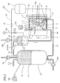
Figure 1 is a schematic side view, with some parts in cross section and others cut away to better illustrate others, of a first embodiment of the ceramic manufacturing installation according to the present invention; -
Figure 2 is a schematic side view, with some parts in cross section and others cut away to better illustrate others, of a second embodiment of the ceramic manufacturing installation according to the invention; -
Figure 3 is an exploded perspective view of a half mould used for the manufacture of ceramic products and applicable to the installation; -
Figure 4 is a perspective view partially in cross section illustrating the assembled half mould ofFigure 3 ; -
Figure 5 illustrates the half mould ofFigures 3 and4 in a partial planar section; -
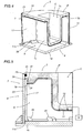
Figure 6 is a schematic side view, with some parts in cross section, of the porous resin part of a part of a shell mould, with the respective sealed covering element, used in the installation according to the invention; -
Figure 7 is a schematic exploded side view of a part of a half mould used in the installation according to an embodiment, and shows, in particular, the porous resin portion and a sealed covering element; -
Figure 8 is a side view, with some parts cut away and others in cross section, of the mould part ofFigure 6 but equipped with a different embodiment of the positioning elements from those ofFigure 5 ; -
Figure 9 is a side view, with some parts cut away and others in cross section, again of the mould part ofFigure 6 but equipped with yet another different embodiment of the positioning elements. - With reference to the accompanying drawings, in particular
Figures 1 and2 , the installation according to the invention is used for manufacturing ceramic products, in particular but not limited to, ceramic sanitaryware (such as, for example, washbasins, toilet bowls, bidets, shower trays, and the like). - This installation, labelled 100 in its entirety, comprises a
mould 1 divided into at least twoparts - Each
part mould 1 is briefly described below in order to give a clear overview of the invention. - Basically, each
part mould 1 is composed of a body delimited by: an outside surface comprising arear surface lateral surface inside surface front contact surface respective contact surface other part mould 1 when the twoparts mould 1 are closed (for the respective references, see alsoFigures 6 and 7 ). - The body delimited by these surfaces is mostly composed, by way of non-limiting example, by one or more volumes of permeable or porous materials stably connected to each other.
- The two
parts Figures 1 and2 ), in such a way as to join or detach the twoparts - When the two
parts - The feeding of the liquid (and also of other fluids, as will become clearer as this description continues) is accomplished by respective first feed means 10 at pressures P that differ according to the product casting cycle (the first feed means 10 being described in more detail below).
- In the embodiment of the
installation 100 illustrated, the drive means 4 are in the form of a cylinder for moving thepart 2 which is in turn supported by a crossbar T, but this embodiment must be considered as a non-limiting example of how to implement the invention, since themeans 4 may be embodied by other floor or overhead rail or guide systems for both single-mould and multiple mould installations, without thereby departing from the scope of the invention. - As also shown in
Figures 1 and2 , at least one of the parts - the one labelled 2 in this non-limiting example - is equipped withmeans 6 for containing a fluid and encompassing at least the above mentioned rear and lateraloutside surfaces mould 1part 2 itself; these containment means 6 are associated with thepart 2 in such a way that during the product casting cycle the fluid constantly applies reaction forces FR to compensate the forces SF acting on thepart 2 of themould 1, in the directions defined by the shape of theinside surface 2c of themould part 2. - In the embodiment illustrated, again by way of example, these containment and control means 6 are interposed, in use, between the
mould part 2 and the drive means 4. -
Figure 2 also shows that theother mould part 3 may also be equipped with containment and control means 6' acting on the rear and lateraloutside surfaces mould part 3. - For simplicity of description, reference is hereinafter made only to the containment means 6 of only one of the mould parts since the structure is substantially the same for the other part of the mould, too.
- In the configuration illustrated here, the part of the mould labelled 2, known in the jargon of the trade as the female part, will be considered.
- Looking in more detail (see also
Figures 3 to 5 ), the containment and control means 6 comprise a sealedcontainment element 7 associated with themould part 2 and surrounding the rearoutside surface 2p and the lateraloutside surface 2s of themould part 2 itself. - The
containment element 7 is equipped withmeans 8 for pumping compensation fluid in and out of at least onecompensation chamber 9 defined between thecontainment element 7 itself and the rear and lateraloutside surfaces mould part 2. - In particular, the
means 8 for pumping compensation fluid in and out of thecompensation chamber 9 are correlated with theaforementioned means 10 for controlling the fluids in the cavity C: thus, in thechamber 9, the pressures P present in the moulding cavity C can be compensated in real time with a suitable pressure P' in thecompensation chamber 9. - It follows that the forces SF acting on the
mould part 2 along the aforementioned directions normal to thesurface 2c of themould part 2 are, so to speak, proportionally balanced by reaction forces FR. - At least the
outside surface 2p of themould part 2 has aprotective jacket 11 or 12 (that might be, without limiting the invention, of the laminated type), sealed and shaped to match the profile of the rearoutside surface 2p of the part 2 (see alsoFigure 7 ) and creating a separating surface between thecompensation chamber 9 and the rear outsidesurface 2p itself, or the thickness of the permeable material constituting the body of themould part 2. - This structural combination makes it possible to choose from different structural solutions, meaning geometrical shapes, of the mould part contained within the
compensation chamber 9, without affecting the quality of the end product. - By way of non-limiting example, the shape of the
mould part 2 shown inFigure 1 has large, geometrically regular outside surfaces, while inFigures 2 to 5 and7 , the shape of thepart 2 of themould 1 has geometrically complex outside surfaces, where the profile of the rearoutside surface 2p and the profile of the workingsurface 2c - 2f, joined by thelateral transition surface 2s (in practice the edge), are substantially parallel. - In the second situation, the mould part is like a "carving" in space, with the material making up the body, that is, the substantially active and permeable part of the mould part, having a reduced thickness.
- This architecture offers considerable advantages, such as, for example, a lighter overall weight of the system and hence mould movement systems that are more economical.
- Another advantage is that the thinner the resin layer is in the thrust direction in which the forces are applied to the inside surface during the casting cycle, the lesser the effects of its compressibility on the cast product.
- Obviously, as mentioned previously, each rear outside
surface 2p in these two different embodiments has a matchingly shaped, sealedprotective jacket 11 creating a separating surface between thecompensation chamber 9 and the rearoutside surface 2p. -
Figures 6 and8 illustrate another embodiment of the body of themould part 2, where the rearoutside surface 2p of thepart 2 of themould 1 has a standard geometrical profile which, in this particular case, is rounded or shell-like, irrespective of the shape of thesurface 2c wet by the slip. - In this case too, the rear outside
surface 2p of the "shell" has a matchingly shapedprotective jacket 12 for separating thecompensation chamber 9 from the rearoutside surface 2p. - In this embodiment, the main advantage is, precisely, the possibility of normalizing the mould structure independently of the shape of the cavity C, allowing the processes for manufacturing the jackets and auxiliary equipment to be standardized and thus significantly reducing overall costs.
- The
jacket - In view of the particular structural combination between the rear
outside surface 2p and thejacket jacket mould part 2 or made directly in themould part 2, said means being connected to anexternal service unit 14 of the aforementioned drainage system (illustrated as a block inFigure 5 , since it is of known type). - To this must be added the fact that precisely because there are drainage channels between the rear
outside surface 2p and thejacket unit 14 pumps fluids into the drainage system under pressure (for example when cleaning / rinsing the mould). - A closer look at the
compensation chamber 9 reveals that the latter comprises theaforementioned containment element 7 which in turn comprises at least the following (seeFigures 3 ,4 and 5 ): - a
rigid element 22 defining the walls of thecompensation chamber 9; - a
base plate 19 associated with therigid element 22; - sealing means 21 acting between the
rigid element 22 and themould part 2. - Besides these components, there is also a positioning element or
spacer 17 associated with the lateral outsidesurface 2s of thepart 2, through respective first fastening means 18, and designed to position themould part 2 relative to thebase plate 19; therigid element 22 is placed over thespacer 17. - Through second fastening means 20, the
spacer 17 can also be associated with thebase plate 19 of thecompensation chamber 9. - More specifically, the sealing means 21 are positioned and active between the lateral
outside surface 2s of themould part 2 and therigid element 22. - As shown in
Figures 1 and2 , thebase plate 19 may (in one non-limiting example embodiment) be equipped with an opening leading into thechamber 9 and occupied by asecond conduit 8a (there is also afirst conduit 27, described below, forming part of the installation 100) for the passage of fluid and forming part of theaforementioned means 8 for pumping fluid in and out of the sealedcompensation chamber 9. - Obviously, the
second conduit 8a may be placed in communication with thecompensation chamber 9 through an opening made in theelement 22. - The
plate 19 may also be provided with a second opening occupied by a thirdsafety relief conduit 23 leading to a maximum pressure valve for the sealedcompensation chamber 9. - Obviously, the
third conduit 23 may also be connected to thecompensation chamber 9 through theelement 22 by way of a suitable opening. - In the case illustrated, the
base plate 19 is connected to themeans 4 that move the half-mould 2 (through the aforementioned crossbar T) acting in both directions along a predetermined clamping line S in such a way as to join or detach the twoparts - As regards the possible mechanical solutions present, the above mentioned first fastening means may be in the form of a first
enlarged end edge 18 made on thespacer 17 and engageable with a matchingfirst slot 24 formed on the lateral outsidesurface 2s of thepart 2. - The above mentioned second fastening means may be in the form of a plurality of
brackets 20 located on thebase plate 19 and engageable with a secondenlarged end edge 17a of the spacer 17 (seeFigures 4 and 5 ) . - The sealing means may comprise a gasket or seal 21 (in this case, for example, a ring seal) made of incompressible material housed in a matching
second slot 25 in themould part 2 and retained, on the opposite side, by the aforementioned rigid, reinforcingelement 22. -
Figures 3 and4 illustrate an example of afemale mould part 2 where thespacer 17 is divided into at least two half-parts part 2 and which can be associated with both thepart 2 and thebase plate 19 through the first fastening means 18 and the second fastening means 20. - An alternative embodiment of the structure described above is shown in
Figures 6 ,8 and 9 . - In this embodiment, the
mould part 2 is of the rounded or shell type, equipped with the above mentionedjacket 12 to cover the rearoutside surface 2p and having a circular flange connecting it to the lateral outsidesurface 2s. - In
Figure 8 , the basic elements of the structure of thecontainment element 7 are the same as those of the previous embodiment except for thepositioning element 17 which, in this case, comprises two or more columns orpillars 17d each associated at one end to thebase plate 19 and at the other end to the flanged zone of the rearoutside surface 2p. - The
pillars 17d may be equipped with elastic blocks TE for joining the flange to the bottom in such a way as to obtain elastic compliance providing defined structural rigidity during the different operating steps, in particular, through axial absorption of thepillars 17d. - Yet another embodiment is illustrated in
Figure 9 , where thepositioning element 17 is in the form of two ormore tie rods 17t each associated at one end to thebase plate 19 and at the other end to the flanged zone of the rearoutside surface 2p. - The end of each
tie rod 17t is inserted in arespective seat 19t in thebase plate 19, with aspring 17m fitted round it, the spring being retained at one end by the end head of therespective tie rod 17t and at the other end by the upper inside wall of theseat 19t. - The load of the
spring 17m, in a non-working situation, keeps themould part 2 and thebase plate 19 closer together (minimum gap predetermined also thanks to alimit stop tooth 22e located along the inside surface of the element 22), while the gap widens at the beginning of the operating cycle on account of the increased pressure inside thechamber 9 and, hence, the pushing force exerted by the fluid on the rearoutside surface 2p, which gradually overcomes the pulling force of thespring 17m. - The positioning element embodiments described up to now and which refer to the embodiments showed in
figures 6 ,8 and 9 allow adaptable, safe contact between the working surfaces of the twoparts mould 1. - It follows that with a mould structured in this way, even the rest of the
ceramic casting installation 100 must be equipped with components in addition to the traditional ones such as the aforementioned means 10 for controlling the service fluids in the cavity C (ceramic casting liquid and air for draining out the excess liquid / consolidating the product). - Suffice it to say that the pressure P of the casting liquid or slip and of the air assumes values that vary as a function of time (P = P(t)) during the casting cycle, and the counter-thrust pressure P' of the compensation fluid is a linear function of the pressure inside the cavity C, and therefore even P' = P'(t)=K1 + K2*P(t).
- These values are controlled by
respective sensors pressurization tank 26 and, in the case of the compensation fluid, inside the compensation chamber 9 (seeFigures 1 and2 ). - Returning now to
Figures 1 and2 , the first liquid / air feed means 10 may comprise: - the first
casting liquid tank 26 connected by afirst conduit 27 to the moulding cavity C; and - adjustable means 28 for introducing a gaseous fluid into the
first tank 26 in such a way as to pressurize thefirst tank 26 and thus force the liquid into the cavity C at pressures P which are predetermined as a function of the product casting cycle. - The casting liquid is fed into the
tank 26 by suitable feed means 26a. - In addition to these components, there is a
second tank 29 containing the aforementioned compensation fluid that can be fed into thecompensation chamber 9 through the aforementionedsecond conduit 8a. - The second tank 29 (equipped with respective independent
adjustable means 28a for introducing the gaseous fluid and means 28b for supplying the compensation fluid) is connected through afourth conduit 30 to thefirst tank 26 at the zone subjected to the thrust of the pressurized gaseous fluid in such a way as to enable the pressure P' present in thesecond tank 29 to be equalized with the pressure P present in thefirst tank 26, that is to say, to correlate the counter-thrust pressure of the compensation fluid in thechamber 9 with the thrust pressure that forces the liquid / air into the casting cavity C. - Obviously, as we shall see later, the correlation between the pressure in the cavity C and the pressure of the compensation fluid is maintained also during the decompression, draining off and consolidation steps thanks to the presence of the
sensors second tank - The
numerals 40 and 40' inFigures 1 and2 denote blocks, located onfourth conduits 30 and 30', representing generic control means for correctly correlating the two pressures P and P', while supporting the possibility of initially preloading the chamber orchambers 9, 9' with compensation fluid PP before the casting cycle starts, that is to say, before the casting liquid starts flowing in. - To enable the compensation fluid to flow in and out correctly without mixing with the gaseous fluid, the
second tank 29 may be equipped with apartition membrane 31 keeping the gaseous fluid separate from the compensation fluid. - The
membrane 31 may be of the elastic type and mobile in both directions along the second tank 29 (see arrows F31). - As regards the compensation fluid, this may be a liquid and, more specifically, without limiting the invention, water, while the pressurizing gaseous fluid is air.
- The dashed lines in
Figure 2 indicate the elements that may be present on theother part 3 of the mould, that is to say, a third compensation fluid tank 29', identical to thesecond tank 29, and equipped with a conduit 8'a for connecting a compensation chamber 9' and also connected to thefirst tank 26 by way of another conduit 30'. - With an
installation 100 structured in this way, a method for manufacturing a ceramic product may comprise at least the following steps: - a) moving the two
parts rigid element 22 to come into contact with the corresponding rigid element of themould part 3; - b) preloading the
chamber 9 to a defined pressure PP by feeding fluid into it; - c) filling the cavity C with casting liquid at a pressure P(t) and further pressurizing the
compensation chamber 9 with the respective fluid at the correlated pressure P' (t) (being the preloading pressure PP plus the pressure KP(t)); - d) pressurizing the casting liquid in the cavity C to a pressure P(t) and correspondingly pressurizing the compensation fluid in the
chamber 9 to a pressure P'(t), in order to form the thickness of the product by also draining off part of the liquid (water) through theaforementioned draining channels - e) decompressing the cavity C, and hence the casting liquid still present in it, to a predetermined pressure P and correspondingly decompressing the fluid in the
compensation chamber 9 to the pressure P'; - f) completely emptying the used slip out of the cavity C until reaching the minimum pressure and correspondingly decompressing the
compensation chamber 9; - g) consolidating the ceramic product in air at a pressure P(t) and consequently bringing the pressure in the
compensation chamber 9 up to P'(t); - h) decompressing the cast product to P=0 and consequently returning P' to PP;
- i) opening the two
parts - j) resetting P' and extracting the cast product from the second mould part, which is detached from the product.
- This method, which regards the basic steps in the casting of a ceramic product, makes it possible, thanks to the reaction forces exerted on the outside surface of the mould, to control the forces acting on the inside surface: not only in the directions at right angles (and hence transversal) to the clamping line S, but also in the directions parallel to the clamping line S and the respective components derived from the rear
outside surface 2p of the mould part. - Thus, the installation structured in this way fully achieves the above mentioned aims thanks to the overall control of the forces inside the mould by a fluid which compensates these forces in modulated manner at all stages of the casting process and in all dimensions of the mould.
- This modulated control improves reaction on the mould and eliminates potential deformation of the mould, thereby preventing elastic contractions that could have negative effects on the quality of the product being cast.
- The invention described above is susceptible of industrial application. Moreover, all the details of the invention may be substituted by technically equivalent elements.
Claims (25)
- An installation for the manufacture of ceramic products, the installation (100) comprising at least one mould (1) divided into at least two parts (2, 3) forming an internal cavity (C) where the ceramic product is formed, and mobile towards and away from each other, under the action of respective drive means (4) acting in both directions along a predetermined clamping line (S), in such a way as to join or detach the parts (2, 3) to/from each other; each part (2, 3) of the mould (1) comprising at least one rear outside surface (2p, 3p) and one lateral outside surface (2s, 3s); at least one of the parts (2, 3) of the mould (1) being equipped with means (6) for containing and controlling a fluid, encompassing at least the rear outside surface (2p, 3p) and the lateral outside surface (2s, 3s) of the mould (1) part (2, 3) and being associated with the part (2, 3) of the mould (1) in such a way that during the product casting cycle the forces (SF) acting on the part (2, 3) of the mould (1) are constantly compensated; said second containment and control means (6) comprising a hermetically sealed containment element (7) associated with the mould part (2, 3) to surround the rear outside surface (2p, 3p) and the lateral outside surface (2s, 3s) of the mould part (2, 3); said containment element (7) being equipped with means (8) for pumping compensation fluid in and out of a compensation chamber (9) defined between the containment element (7) itself and the rear (2p, 3p) and lateral (2s, 3s) outside surfaces of the mould part (2, 3) ; wherein the containment element (7) comprises at least:- a rigid element (22) defining the walls of the compensation chamber (9);- a base plate (19) associated with the rigid element (22);- sealing means (21) acting at least between the rigid element (22) and the mould part (2, 3); the containment element being characterized in that it further comprises:- a positioning or spacing element (17), located inside the rigid element (22) and associated bilaterally with the flanged zone of the rear outside surface (2p) and to the base plate (19), through respective first and second fastening means, said element (17) being designed to position the mould part (2, 3) relative to the base plate (19).
- The installation according to claim 1, characterized in that the other part (3, 2) of the mould (1) is also equipped with containment and control means (6') encompassing the rear outside surface (3p, 2p) and the lateral outside surface (3s, 2s) of said part (3, 2) of the mould (1).
- The installation according to claim 1 or 2, characterized in that the containment and control means (6) are positioned and active on the rear outside surface (2p, 3p) and on the lateral outside surface (2s, 3s) of the mould part (2, 3) and, in use, are interposed between said part (2, 3) and the drive means (4).
- The installation according to claim 1, where a moulding cavity (C), defined by inside surfaces (2c, 3c) of the part (2, 3) wet by a casting liquid, can be supplied with said product casting liquid through respective first means (10) for controlling the service fluids in the cavity (C) at different pressures (P) according to the different steps in the product casting cycle, the installation being characterized in that the means (8) for pumping containment and control compensation fluid in and out of the compensation chamber (9) are correlated with the first means (10) for controlling the service fluids, so that, in the chamber (9), the pressures (P) in the moulding cavity (C) can be compensated in real time with a suitable pressure (P') in the compensation chamber (9).
- The installation according to claim 1, characterized in that at least the rear outside surface (2p, 3p) of the part (2, 3) of the mould (1) has a protective jacket (12), sealed and shaped to match the profile of the rear outside surface (2p, 3p) of the part (2, 3) and creating a separating surface between the compensation chamber (9) and the rear outside surface (2p, 3p) of said part (2, 3).
- The installation according to claim 1, where each of the parts (2, 3) of the mould (1) is delimited by: an outside surface comprising the rear surface (2p, 3p) and the lateral surface (2s, 3s), and a working surface comprising an inside surface (2c, 3c), wet by a casting liquid and defining the cavity (C), and a front contact surface (2f, 3f) which abuts the respective contact surface (3f, 2f) of the other mould part (3, 2) when the two mould parts (3, 2) are closed, the installation being characterized in that the rear outside surface of the part (2, 3) of the mould (1) has a profile with a geometrically standardized shape, defined by the thickness of the material the body is made of, irrespective of the shape of the cavity (C); the rear outside surface (2p, 3p) being provided with a matching, sealed protective jacket (12) creating a surface to separate the compensation chamber (9) from the rear outside surface (2p, 3p).
- The installation according to claim 6, characterized in that the rear outside surface of the part (2, 3) of the mould (1) has a rounded or shell-like profile, defined by the thickness of the material the body is made of; the rear outside surface (2p,3p) being provided with a matching, shell-like sealed protective jacket (12) creating a surface to separate the compensation chamber (9) from the rear outside surface (2p, 3p).
- The installation according to claim 6 or 7, characterized in that it comprises means (13, 15) for draining out some of the product casting liquid and interposed between the jacket (12) and the mould part (2, 3) and connected to an external service unit (14) of the drainage system.
- The installation according to claim 6 or 7, characterized in that, between the rear outside surface (2p, 3p) and the jacket (12), it comprises adhesion means to hold them together and oppose the pushing forces created when the external service unit (14) of the drainage system pumps fluids into the drainage means (13, 15) under pressure.
- The installation according to claim 6, 7, 8 or 9 characterized in that the jacket (12) is made of a composite material in order to improve the mechanical strength of the part (2, 3) of the mould (1) which is subjected to unwanted pressure imbalances from both the inside, that is, the inside surfaces (2c, 3c), and the outside of the mould (1), that is, the outside surfaces (2p, 3p; 2s, 3s).
- The installation according to claim 1, characterized in that the base plate (19) is provided with an opening occupied by a second conduit (8a) for the passage of fluid and forming part of the means (8) for pumping fluid in and out of the sealed compensation chamber (9).
- The installation according to claim 1, characterized in that the rigid element (22) is provided with an opening occupied by a second conduit (8a) for the passage of fluid and forming part of the means (8) for pumping fluid in and out of the sealed compensation chamber (9).
- The installation according to claim 1, characterized in that the plate (19) is provided with a second opening occupied by a third safety relief conduit (23) leading to a maximum pressure safety valve for the sealed compensation chamber (9).
- The installation according to claim 1, characterized in that the rigid element (22) is provided with a second opening occupied by a third safety relief conduit (23) leading to a maximum pressure safety valve for the sealed compensation chamber (9).
- The installation according to claim 1, characterized in that the base plate (19) is connected to means (4) for moving the mould part (2, 3) and acting in both directions along a predetermined clamping line (S) in such a way as to join or detach the two parts (2, 3) to/from each other.
- The installation according to claim 1, characterized in that the sealing means comprise a gasket or seal (21) made of incompressible material housed in a matching slot (25) in the mould part (2, 3) and retained, on the opposite side, by the aforementioned rigid element (22).
- The installation according to claim 1, characterized in that the positioning element (17) is in the form of a plurality of columns or pillars (17d) each associated at one end to the base plate (19) and at the other end to the rear outside surface (2p); said pillars (17d) being provided with elastic blocks for conferring elastic compliance that provides defined structural rigidity during the different steps of the casting cycle.
- The installation according to claim 1, characterized in that the positioning element (17) is in the form of a plurality of tie rods (17t) each associated at one end to the base plate (19) and at the other end to the rear outside surface (2p); one end of each tie rod (17t) being inserted in a respective seat (19t) in the base plate (19); the said end of each of the tie rods (17t) having a spring (17m) fitted round it, the spring being retained at one end by the end head of the respective tie rod (17t) and at the other end by the upper inside wall of the seat (19t) so that, when not working, the mould part (2, 3) and the base plate (19) are kept closer together.
- The installation according to claim 4, where the first means (10) for controlling the product casting liquid comprise:- a first casting liquid tank (26) connected by a first conduit (27) to the moulding cavity (C), and- adjustable means (28) for introducing a gaseous fluid into the first tank (26) in such a way as to pressurize the casting liquid in the cavity at pressures (P) which are predetermined as a function of the product casting cycle, the installation being characterized in that it further comprises at least one second tank (29) containing the compensation fluid that can be fed into the compensation chamber (9) through a second conduit (8a).
- The installation according to claim 19, characterized in that the second tank (29) is connected through a fourth conduit (30) to the first tank (26) at the zone subjected to the thrust of the gaseous fluid in such a way as to enable the pressure (P) present in the first tank (26) to be equalized with the pressure (P') present in the second tank (29), that is to say, to correlate the counter-thrust pressure of the compensation fluid in the chamber (9) with the thrust pressure that forces the liquid / air into the moulding cavity (C).
- The installation according to claim 19 or 20, characterized in that the second tank (29) is equipped with a partition membrane (31) keeping the gaseous fluid separate from the compensation fluid.
- The installation according to claim 21, characterized in that the membrane (31) is of the elastic type and mobile along the second tank (29).
- The installation according to claim 19 or 20, characterized in that the compensation fluid is a liquid.
- The installation according to claim 19 or 20, characterized in that the compensation fluid is a liquid and, in particular, is water.
- The installation according to claim 19 or 20, characterized in that the gaseous thrust fluid is air.
Priority Applications (3)
| Application Number | Priority Date | Filing Date | Title |
|---|---|---|---|
| EP13178363.1A EP2660025B1 (en) | 2008-03-17 | 2009-03-06 | Installation for the manufacture of ceramic products |
| PL13178363T PL2660025T3 (en) | 2008-03-17 | 2009-03-06 | Installation for the manufacture of ceramic products |
| PL09154483T PL2103401T3 (en) | 2008-03-17 | 2009-03-06 | Installation for the manufacture of ceramic products. |
Applications Claiming Priority (1)
| Application Number | Priority Date | Filing Date | Title |
|---|---|---|---|
| IT000173A ITBO20080173A1 (en) | 2008-03-17 | 2008-03-17 | PLANT FOR THE REALIZATION OF MANUFACTURED PRODUCTS |
Related Child Applications (2)
| Application Number | Title | Priority Date | Filing Date |
|---|---|---|---|
| EP13178363.1A Division EP2660025B1 (en) | 2008-03-17 | 2009-03-06 | Installation for the manufacture of ceramic products |
| EP13178363.1 Division-Into | 2013-07-29 |
Publications (3)
| Publication Number | Publication Date |
|---|---|
| EP2103401A2 EP2103401A2 (en) | 2009-09-23 |
| EP2103401A3 EP2103401A3 (en) | 2011-06-22 |
| EP2103401B1 true EP2103401B1 (en) | 2013-12-11 |
Family
ID=40292659
Family Applications (2)
| Application Number | Title | Priority Date | Filing Date |
|---|---|---|---|
| EP13178363.1A Active EP2660025B1 (en) | 2008-03-17 | 2009-03-06 | Installation for the manufacture of ceramic products |
| EP09154483.3A Active EP2103401B1 (en) | 2008-03-17 | 2009-03-06 | Installation for the manufacture of ceramic products. |
Family Applications Before (1)
| Application Number | Title | Priority Date | Filing Date |
|---|---|---|---|
| EP13178363.1A Active EP2660025B1 (en) | 2008-03-17 | 2009-03-06 | Installation for the manufacture of ceramic products |
Country Status (9)
| Country | Link |
|---|---|
| US (1) | US8057208B2 (en) |
| EP (2) | EP2660025B1 (en) |
| CN (1) | CN101537659B (en) |
| BR (1) | BRPI0900913A2 (en) |
| ES (2) | ES2449155T3 (en) |
| IT (1) | ITBO20080173A1 (en) |
| MX (1) | MX2009002867A (en) |
| PL (2) | PL2660025T3 (en) |
| RU (1) | RU2009109177A (en) |
Families Citing this family (3)
| Publication number | Priority date | Publication date | Assignee | Title |
|---|---|---|---|---|
| CN103231430B (en) * | 2013-04-22 | 2016-01-13 | 袁东福 | In a kind of pottery, low-pressure grouting shaped device |
| CN107009487A (en) * | 2017-05-24 | 2017-08-04 | 华中科技大学 | A kind of hot-injection molding system of high stability |
| CN107042572A (en) * | 2017-06-13 | 2017-08-15 | 佛山市鸣门卫浴家居有限公司 | A kind of ceramic sanitary appliance high-pressure slip-casting shaped device |
Family Cites Families (9)
| Publication number | Priority date | Publication date | Assignee | Title |
|---|---|---|---|---|
| US3993727A (en) * | 1974-12-18 | 1976-11-23 | Wallace-Murray Corporation | Fluid-release mold and the method of manufacturing the same |
| US4124058A (en) * | 1977-08-02 | 1978-11-07 | Gladwin Floyd R | Side wall guide for adjustable width continuous casting mold |
| DE3502348A1 (en) * | 1985-01-24 | 1986-07-24 | Gebrüder Netzsch, Maschinenfabrik GmbH & Co, 8672 Selb | Process and device for die casting liquid-containing material |
| JPS6331709A (en) * | 1986-07-26 | 1988-02-10 | 東陶機器株式会社 | Pottery pressure casting molding die |
| JPS6342803A (en) * | 1986-08-08 | 1988-02-24 | 東陶機器株式会社 | Casting molding method and device |
| IT1236072B (en) * | 1989-11-09 | 1992-12-22 | Fabio Leoncini | Stamp for the fabrication of ceramic products, in particular, sanitary articles |
| FR2674934B1 (en) * | 1991-04-05 | 1993-08-20 | Caoutchouc Manuf Plastique | PROCESS FOR THE CONTINUOUS PRODUCTION OF A FLEXIBLE TUBULAR STRUCTURE COMPRISING A MULTILAYER SHEET OF INCORPORATED MICROMETRIC THICKNESS AND FLEXIBLE TUBULAR STRUCTURES PRODUCED ACCORDING TO THIS PROCESS. |
| KR100422743B1 (en) * | 1995-08-26 | 2004-06-26 | 도토기키 가부시키가이샤 | Injection molding method of powder and injection molding method used for injection molding and production method of continuous pore porous body used in injection molding type |
| IT1309747B1 (en) | 1999-04-09 | 2002-01-30 | Sacmi | PRESSURE CASTING APPARATUS WITH MOLDS IN TWO PARTS SANITARY ITEMS AND RELATIVE MOLD |
-
2008
- 2008-03-17 IT IT000173A patent/ITBO20080173A1/en unknown
-
2009
- 2009-03-06 ES ES09154483.3T patent/ES2449155T3/en active Active
- 2009-03-06 EP EP13178363.1A patent/EP2660025B1/en active Active
- 2009-03-06 PL PL13178363T patent/PL2660025T3/en unknown
- 2009-03-06 EP EP09154483.3A patent/EP2103401B1/en active Active
- 2009-03-06 PL PL09154483T patent/PL2103401T3/en unknown
- 2009-03-06 ES ES13178363.1T patent/ES2543575T3/en active Active
- 2009-03-11 BR BRPI0900913-2A patent/BRPI0900913A2/en not_active Application Discontinuation
- 2009-03-13 US US12/403,818 patent/US8057208B2/en not_active Expired - Fee Related
- 2009-03-13 MX MX2009002867A patent/MX2009002867A/en active IP Right Grant
- 2009-03-16 RU RU2009109177/03A patent/RU2009109177A/en not_active Application Discontinuation
- 2009-03-17 CN CN2009101285816A patent/CN101537659B/en active Active
Also Published As
| Publication number | Publication date |
|---|---|
| EP2660025A1 (en) | 2013-11-06 |
| US20090230591A1 (en) | 2009-09-17 |
| EP2103401A2 (en) | 2009-09-23 |
| PL2660025T3 (en) | 2015-10-30 |
| US8057208B2 (en) | 2011-11-15 |
| RU2009109177A (en) | 2010-09-27 |
| ITBO20080173A1 (en) | 2009-09-18 |
| CN101537659B (en) | 2013-01-09 |
| ES2449155T3 (en) | 2014-03-18 |
| BRPI0900913A2 (en) | 2010-05-18 |
| EP2660025B1 (en) | 2015-05-06 |
| PL2103401T3 (en) | 2014-06-30 |
| MX2009002867A (en) | 2009-09-24 |
| CN101537659A (en) | 2009-09-23 |
| ES2543575T3 (en) | 2015-08-20 |
| EP2103401A3 (en) | 2011-06-22 |
Similar Documents
| Publication | Publication Date | Title |
|---|---|---|
| EP2103401B1 (en) | Installation for the manufacture of ceramic products. | |
| KR890004630B1 (en) | Mold used in pressure casting ceramic articles | |
| EP2105224B1 (en) | Casting apparatus | |
| TW200305493A (en) | Molding device | |
| JPH0570565B2 (en) | ||
| US20080075800A1 (en) | Equipment for the manufacture of ceramic sanitary wares | |
| US8701453B2 (en) | Method of reducing cycle time in a hydro-mechanical forming process and a tool for hydro-mechanically forming a part | |
| KR20170110152A (en) | Casting apparatus and casting method | |
| KR920000584B1 (en) | Dry-type rubber pressing method | |
| ITMO20100021A1 (en) | PLANT FOR THE PRESSURE CASTING OF HYGIENE-SANITARY ITEMS | |
| CA2394388A1 (en) | Method for the production of molded parts and device for implementing said method | |
| WO2016092670A1 (en) | Composite material molding method and molding device | |
| CN107983819A (en) | A kind of automobile torsion beam low pressure forming processes and its shaping dies | |
| WO2006091619A3 (en) | Casting process | |
| JP2006321203A (en) | Molding machine | |
| EP3848172B1 (en) | Apparatus for forming ceramic articles through pressure casting | |
| CN100537187C (en) | Outshooting compression shaping device | |
| KR930001662B1 (en) | Wet process cold isostatic pressurization device | |
| KR100450042B1 (en) | Apparatus for pressing tiles | |
| CN213382085U (en) | Sanitary ware shell slip casting mould and use its sanitary ware | |
| CN2931064Y (en) | Vertical compression type mould-clipping mechanism for hot press | |
| SK50182012A3 (en) | Method of production of panel unit from glass plate and frame and device for carrying out this method | |
| CN117840400A (en) | Improved aluminum die casting air hole eliminating and forming structure | |
| JPH02220817A (en) | Molding device for composite material | |
| RO119285B1 (en) | Installation and method for making lens-shaped elements |
Legal Events
| Date | Code | Title | Description |
|---|---|---|---|
| PUAI | Public reference made under article 153(3) epc to a published international application that has entered the european phase |
Free format text: ORIGINAL CODE: 0009012 |
|
| AK | Designated contracting states |
Kind code of ref document: A2 Designated state(s): AT BE BG CH CY CZ DE DK EE ES FI FR GB GR HR HU IE IS IT LI LT LU LV MC MK MT NL NO PL PT RO SE SI SK TR |
|
| AX | Request for extension of the european patent |
Extension state: AL BA RS |
|
| RIN1 | Information on inventor provided before grant (corrected) |
Inventor name: SAPONELLI, ROBERTO Inventor name: BAMBI, DOMENICO Inventor name: QUADALTI, ENRICO |
|
| PUAL | Search report despatched |
Free format text: ORIGINAL CODE: 0009013 |
|
| AK | Designated contracting states |
Kind code of ref document: A3 Designated state(s): AT BE BG CH CY CZ DE DK EE ES FI FR GB GR HR HU IE IS IT LI LT LU LV MC MK MT NL NO PL PT RO SE SI SK TR |
|
| AX | Request for extension of the european patent |
Extension state: AL BA RS |
|
| 17P | Request for examination filed |
Effective date: 20110922 |
|
| 17Q | First examination report despatched |
Effective date: 20111202 |
|
| AKX | Designation fees paid |
Designated state(s): ES IT PL PT TR |
|
| REG | Reference to a national code |
Ref country code: DE Ref legal event code: R108 Effective date: 20120229 |
|
| GRAP | Despatch of communication of intention to grant a patent |
Free format text: ORIGINAL CODE: EPIDOSNIGR1 |
|
| INTG | Intention to grant announced |
Effective date: 20130708 |
|
| GRAS | Grant fee paid |
Free format text: ORIGINAL CODE: EPIDOSNIGR3 |
|
| GRAA | (expected) grant |
Free format text: ORIGINAL CODE: 0009210 |
|
| AK | Designated contracting states |
Kind code of ref document: B1 Designated state(s): ES IT PL PT TR |
|
| REG | Reference to a national code |
Ref country code: ES Ref legal event code: FG2A Ref document number: 2449155 Country of ref document: ES Kind code of ref document: T3 Effective date: 20140318 |
|
| REG | Reference to a national code |
Ref country code: PL Ref legal event code: T3 |
|
| PG25 | Lapsed in a contracting state [announced via postgrant information from national office to epo] |
Ref country code: PT Free format text: LAPSE BECAUSE OF FAILURE TO SUBMIT A TRANSLATION OF THE DESCRIPTION OR TO PAY THE FEE WITHIN THE PRESCRIBED TIME-LIMIT Effective date: 20140411 |
|
| PLBE | No opposition filed within time limit |
Free format text: ORIGINAL CODE: 0009261 |
|
| STAA | Information on the status of an ep patent application or granted ep patent |
Free format text: STATUS: NO OPPOSITION FILED WITHIN TIME LIMIT |
|
| 26N | No opposition filed |
Effective date: 20140912 |
|
| PGFP | Annual fee paid to national office [announced via postgrant information from national office to epo] |
Ref country code: TR Payment date: 20230227 Year of fee payment: 15 Ref country code: PL Payment date: 20230224 Year of fee payment: 15 Ref country code: IT Payment date: 20230221 Year of fee payment: 15 |
|
| P01 | Opt-out of the competence of the unified patent court (upc) registered |
Effective date: 20230527 |
|
| PGFP | Annual fee paid to national office [announced via postgrant information from national office to epo] |
Ref country code: ES Payment date: 20230403 Year of fee payment: 15 |