EP2103174B1 - Komponente für ein hörgerät und verfahren zur herstellung einer komponente für ein hörgerät - Google Patents
Komponente für ein hörgerät und verfahren zur herstellung einer komponente für ein hörgerät Download PDFInfo
- Publication number
- EP2103174B1 EP2103174B1 EP07700143.6A EP07700143A EP2103174B1 EP 2103174 B1 EP2103174 B1 EP 2103174B1 EP 07700143 A EP07700143 A EP 07700143A EP 2103174 B1 EP2103174 B1 EP 2103174B1
- Authority
- EP
- European Patent Office
- Prior art keywords
- laser
- slab
- hearing aid
- component
- providing
- Prior art date
- Legal status (The legal status is an assumption and is not a legal conclusion. Google has not performed a legal analysis and makes no representation as to the accuracy of the status listed.)
- Active
Links
Images


Classifications
-
- H—ELECTRICITY
- H04—ELECTRIC COMMUNICATION TECHNIQUE
- H04R—LOUDSPEAKERS, MICROPHONES, GRAMOPHONE PICK-UPS OR LIKE ACOUSTIC ELECTROMECHANICAL TRANSDUCERS; ELECTRIC HEARING AIDS; PUBLIC ADDRESS SYSTEMS
- H04R25/00—Electric hearing aids
- H04R25/65—Housing parts, e.g. shells, tips or moulds, or their manufacture
- H04R25/658—Manufacture of housing parts
-
- H—ELECTRICITY
- H04—ELECTRIC COMMUNICATION TECHNIQUE
- H04R—LOUDSPEAKERS, MICROPHONES, GRAMOPHONE PICK-UPS OR LIKE ACOUSTIC ELECTROMECHANICAL TRANSDUCERS; ELECTRIC HEARING AIDS; PUBLIC ADDRESS SYSTEMS
- H04R25/00—Electric hearing aids
- H04R25/65—Housing parts, e.g. shells, tips or moulds, or their manufacture
-
- Y—GENERAL TAGGING OF NEW TECHNOLOGICAL DEVELOPMENTS; GENERAL TAGGING OF CROSS-SECTIONAL TECHNOLOGIES SPANNING OVER SEVERAL SECTIONS OF THE IPC; TECHNICAL SUBJECTS COVERED BY FORMER USPC CROSS-REFERENCE ART COLLECTIONS [XRACs] AND DIGESTS
- Y10—TECHNICAL SUBJECTS COVERED BY FORMER USPC
- Y10T—TECHNICAL SUBJECTS COVERED BY FORMER US CLASSIFICATION
- Y10T29/00—Metal working
- Y10T29/49—Method of mechanical manufacture
- Y10T29/49002—Electrical device making
-
- Y—GENERAL TAGGING OF NEW TECHNOLOGICAL DEVELOPMENTS; GENERAL TAGGING OF CROSS-SECTIONAL TECHNOLOGIES SPANNING OVER SEVERAL SECTIONS OF THE IPC; TECHNICAL SUBJECTS COVERED BY FORMER USPC CROSS-REFERENCE ART COLLECTIONS [XRACs] AND DIGESTS
- Y10—TECHNICAL SUBJECTS COVERED BY FORMER USPC
- Y10T—TECHNICAL SUBJECTS COVERED BY FORMER US CLASSIFICATION
- Y10T29/00—Metal working
- Y10T29/49—Method of mechanical manufacture
- Y10T29/49002—Electrical device making
- Y10T29/49005—Acoustic transducer
-
- Y—GENERAL TAGGING OF NEW TECHNOLOGICAL DEVELOPMENTS; GENERAL TAGGING OF CROSS-SECTIONAL TECHNOLOGIES SPANNING OVER SEVERAL SECTIONS OF THE IPC; TECHNICAL SUBJECTS COVERED BY FORMER USPC CROSS-REFERENCE ART COLLECTIONS [XRACs] AND DIGESTS
- Y10—TECHNICAL SUBJECTS COVERED BY FORMER USPC
- Y10T—TECHNICAL SUBJECTS COVERED BY FORMER US CLASSIFICATION
- Y10T29/00—Metal working
- Y10T29/53—Means to assemble or disassemble
- Y10T29/5313—Means to assemble electrical device
-
- Y—GENERAL TAGGING OF NEW TECHNOLOGICAL DEVELOPMENTS; GENERAL TAGGING OF CROSS-SECTIONAL TECHNOLOGIES SPANNING OVER SEVERAL SECTIONS OF THE IPC; TECHNICAL SUBJECTS COVERED BY FORMER USPC CROSS-REFERENCE ART COLLECTIONS [XRACs] AND DIGESTS
- Y10—TECHNICAL SUBJECTS COVERED BY FORMER USPC
- Y10T—TECHNICAL SUBJECTS COVERED BY FORMER US CLASSIFICATION
- Y10T29/00—Metal working
- Y10T29/53—Means to assemble or disassemble
- Y10T29/5313—Means to assemble electrical device
- Y10T29/53174—Means to fasten electrical component to wiring board, base, or substrate
Definitions
- the present invention relates to components for hearing aids.
- the invention further relates to a method for manufacturing a component for a hearing aid.
- Hearing aids generally include a range of components such as housing, internal electronic circuitry, lid, switches and buttons.
- ITE hearings aids generally comprise a shell, which anatomically duplicates the relevant part of the user's ear canal.
- a receiver is placed in the shell in communication with an acoustic outlet port arranged at the proximal end, i.e. the end of the shell adapted for being situated in the ear canal close to the tympanic membrane.
- the distal end of the shell i.e. the opposite end, intended to be oriented towards the surroundings, is closed by a faceplate subassembly, connected to the receiver by leads.
- the faceplate subassembly incorporates a microphone, electronics, a battery compartment and a hinged lid. The microphone communicates with the exterior through a port, which may covered by a grid.
- a BTE hearing aid comprises a housing adapted for resting over the pinna of the user and an ear piece adapted for insertion into the ear canal of the user and serving to convey the desired acoustic output into the ear canal.
- the earpiece is connected to the BTE housing by a sound conduit or, in case it houses the receiver, by electric leads. In either case it has an output port for conveying the sound output.
- a hearing aid During normal use, a hearing aid is exposed to environmental factors such as wear, moisture, sweat, ear wax, fungi, bacteria, dirt and water. Some of those factors may have a corroding influence; others may cause development of an undesired biofilm or of an otherwise irregular surface patina. Corrosion may be controlled by the selection of durable materials. However the environmental factors may over time create an unsightly appearance.
- WO-A1-00/03561 provides an in-the-ear hearing aid wherein the acoustic outlet port is protected against contamination by earwax by means of an earwax guard, which is inserted in port.
- An elastic hose connects the port to a receiver.
- the earwax guard comprises an essentially tubular element with a through-going cavity and an abutment collar in one end for sealing abutment against an edge of the hearing aid housing adjacent the port.
- EP-A2-1432285 shows a method for hydrophobic coating of components for a hearing aid in areas of gaps, slits and apertures, such as for the battery lid, the battery compartment, the housing or a switch, for the purpose of ensuring entry of oxygen, which is needed for proper operation of Zn-air batteries, while controlling the entry of liquids.
- the coating comprises hydrophobic or oleophobic materials applied through immersion or spraying.
- DE-A1-102004062279 shows an earwax guard for a hearing aid, which has been provided with an oleophobic or biofilm-inhibiting coating.
- EP-A2-1458217 shows an acoustic filter of a hearing instrument, detachably placed nearby or at the opening for the acoustic output of the instrument.
- the filtering element is made of a polymer material, a synthetic, metallic or ceramic material or a fabric-like material.
- EP-A2-1432285 provides a method for hydrophobic coating of a hearing aid for the purpose of preventing entry of moisture into crevices and openings of the housing.
- US-3354022 provides a water-repellant surface having high and low portions with an average distance between high portions of not more than 1000 microns and an average height of high portions of at least 0.5 times the average distance between them; and having an air content of at least 60 %.
- the air content of the surface is determined by taking an imaginary plane parallel to the surface passing through the tops of the high portions of the surface and measuring at this plane the percentage of the total surface area that is air.
- the surfaces may be coated with a solid having a water contact angle of greater than 90 degrees. These surfaces are highly water repellant.
- WO-A1-0058415 provides a device for the loss-free transport or emptying of hydrophilic liquids, which device has raised areas and cavities on the side facing the liquid, the distance between the raised areas being between 0.1 and 200 microns and the height of said raised areas between 0.1 and 100 microns, and the raised areas being hydrophobic.
- WO-A2-2005079373 provides a protective cap assembly for a CIC hearing aid.
- the assembly comprises a perforated cap configured to be mounted over the lateral end of the hearing aid to protect the hearing aid from contaminants. At a least a portion of the cap includes a protective coating and a plurality of perforations.
- the cap can also be configured to be mounted over the microphone assembly, or the battery assembly and even a portion of the receiver assembly.
- JP-A-2000158157 provides a method of manufacturing a component comprising providing a slab, processing the surface of the slab with a laser to provide a microstructured surface, which surface has an air content of at least 50 %, and treating the microstructured surface with a moisture repellent matter.
- the invention in a first aspect, provides a methond of manufacturing a component, as recited in claim 1.
- This provides a method for manufacturing of components with superior properties with respect to repellency to water and bodily fluids.
- Components on which this method is of advantage include housings, casings, shells, faceplates, grids, hooks, lids, battery drawers, buttons and manipulators, etc.
- the component comprises a slab with an exterior surface that has been microstructured.
- the inventors have discovered that microstructuring of the surface enhances the water repellant properties.
- the term exterior surface is here used to designate a surface intended for generally facing the environment exterior to the hearing aid, as opposed to a surface intended to face inner parts of the hearing aid.
- the component has enhanced repellency to moisture and bodily fluids.
- Suitable substances for the coatings are silanes such as perfluoroalkylsilanes or alkylsilanes.
- the silanes are chemically attached to the surface by reaction between hydroxy groups on the silane and on the surface, forming a self assembled monolayer (SAM).
- SAM self assembled monolayer
- Suitable surfaces may be produced by selecting appropriate materials and providing a micro-surface structure with high air content.
- fig. 1 illustrates an ITE hearing aid 1, generally comprising a shell 2, a faceplate 3, a lid 5, a sound inlet port 6 and a sound output port 7.
- the hearing aid 1 is adapted to be positioned in the auditory canal of a user with the sound output port 7 facing the user's tympanic membrane.
- Fig. 1 also shows a push button 4 arranged in the lid. The push button serves to allow the user to input commands, e.g. stepping through different programs to enter a selected one.
- Fig. 2 shows a BTE hearing aid 19 according to a first embodiment, this embodiment being essentially styled with hook and casing in one integral piece.
- This embodiment also has battery drawer 15 with battery drawer protrusion 16, and battery drawer nose 17.
- the Fig. 2 embodiment features a lock gripping portion 18, which is a manipulator that must be engaged by the tip of a nail or a pencil to permit opening the drawer for removal of the battery.
- a lock gripping portion 18 which is a manipulator that must be engaged by the tip of a nail or a pencil to permit opening the drawer for removal of the battery.
- FIG. 3 illustrates a BTE hearing aid 8 according to the second embodiment, in side view.
- This hearing aid 8 comprises BTE housing 9, generally consisting of casing 10, hook 11, sound tube 12 and ear piece 13.
- the hearing aid has various details such as microphone grid 20, rocker button 14, battery drawer 15, battery drawer protrusion 16, and battery drawer nose 17.
- the rocker button is used for permitting the user to turn up or down the volume.
- the battery drawer may be partially opened by engaging the protrusion 16 for switching off the hearing aid, and closed to switch on the hearing aid again.
- the battery drawer may also be fully opened for removing the battery by engaging the nose 17.
- WO-A1-2004073351 For a further explanation about these details reference may be had to WO-A1-2004073351 .
- Fig. 4 shows the BTE hearing aid of Fig. 3 in rear view. Reference may be had to the explanation given in relation to Fig. 3 .
- components of the hearing aids may be treated to achieve enhanced surface properties.
- Components where this can be used to advantage comprise housings, casings, shells, faceplates, grids, hooks, lids, battery drawers, buttons and manipulators.
- enhanced surface properties towards aqueous and oily substances signifies an improved ability of the surface to repel such substances.
- the ability of a solid surface to repel a liquid substance can be determined in terms of wetting.
- ⁇ n denotes the contact angle of a water droplet on a normal untreated surface
- ⁇ m denotes the contact angle of a water droplet on a modified surface.
- the contact angle is normally less than 90°. It is well known in the art to coat a solid with a hydrophobic layer in order to increase the contact angle and thereby obtain a moisture repellent surface. Such a surface coating may typically increase the contact angle of water to around 115-120°.
- Fig. 6 shows a water droplet on a surface, which has been modified according to the invention.
- the increased contact angle largely exceeds 90°.
- the contact angle of water exceeds 145° for a variety of materials.
- the obtained surface characteristics may be termed super-hydrophobic.
- the modified materials obtained super-oleophobic surface characteristics as will also become clear in the following.
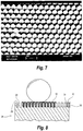
- Fig. 7 shows an example of a laser structured surface of a slab for a component according to the invention as seen through a microscope.
- This slab may represent a part of a component of a hearing aid, e.g. a part of a housing, a casing, a shell, a faceplate, a grid, a hook, a lid, a battery drawer, a button, or a manipulator, etc.
- the surface structuring is preferably realized on lateral scales that are much larger than characteristic sizes for atoms and molecules as well as for grains or other sub-nanometer structures, but not larger than 1000 microns. This is referred to as a microstructure.
- the structuring and/or coating can be applied to the entire component surface or it can be applied to a part of it.
- a controlled structuring of at least a part of the surface in the immediate vicinity of the pores is particularly advantageous.
- the applied structure can be periodic, quasi-periodic or random within a certain spatial bandwidth.
- the spatial bandwidth is defined as the range of reciprocal wave numbers of the lateral scales of the structure, the wave number being defined as the reciprocal value of the lateral wavelength of a periodic structure.
- the structure is applied to at least a part of the component surface.
- the average pitch in the surface structure should be 1000 microns or lower.
- the aspect ratio is typically about 1:1 or larger. Good results have been obtained with samples over a broad pitch range, including pitch at 40 microns, 10 microns and 5 microns.
- the surface structuring may be performed by a number of methods, for example by laser processing of the surface with thermal or non-thermal interactions.
- Non-limiting examples of lasers that can be used for surface structuring are CO 2 lasers, solid state lasers, such as Nd:YAG, picosecond lasers and femtosecond lasers. Processes used in the fabrication of micro/nano-electronics or micro/nano-electromechanical systems as well as other etching or electrochemical processes can also be applied.
- components of the hearing aid e.g. housings, casings, shells, faceplates, grids, hooks, lids, battery drawers, buttons and manipulators
- structuring of the component surface may be achieved through suitable structuring of an inner surface of the die used, e.g. by laser drilling, etching, or spark treatment.
- SLA technique sometimes referred to as a rapid prototyping method
- the coating of the surface structured component will now be described.
- the coating may be applied using a gas phase nano-coating process.
- the process is based on applying a hydrophobic coating to a surface using silanes such as perfluoroalkylsilanes or alkylsilanes.
- silanes are chemically attached to the surface by reaction between hydroxy groups on the silane and on the surface, forming a self-assembled monolayer.
- the material to be coated is rendered active by treatment with a plasma, e.g. an oxygen plasma.
- a plasma e.g. an oxygen plasma.
- the plasma treatment both acts as a cleaning of the surface and as a way of making surface reactive by the introduction of hydroxy groups into the surface.
- an adhesion layer that further enhances the reactivity of the surface by creating even more hydroxy groups may then be deposited and, more preferred, a catalyst is added to promote deposition of the adhesion layer. This step is necessary for non-metallic substrates and also for glasses and some metals in order to create stable coatings.
- a silane is then reacted with the activated surface with or without adhesion layer.
- a catalyst is added to promote deposition of the silane.
- Both silane and adhesion layer are preferably deposited using a vapor phase reaction scheme.
- the equipment is designed so as to have a reaction chamber and separate reservoirs containing the different chemistries used (silane, adhesion layer precursor and a catalyst) and a remote plasma source. From each reservoir, well-defined amounts of the different chemistries are evaporated into a vaporization chamber, from where the vapor is injected into the reaction chamber once a specified pressure in the vaporization chamber is reached.
- each reservoir and the vaporization chamber and between the vaporization chamber and the reaction chamber are controlled by valves.
- the reservoirs and the transfer lines may be heated if necessary in order to promote vaporization and to avoid condensation in the transfer lines.
- the reaction chamber may be heated.
- the system is initially pumped so as to keep a low pressure in the reaction chamber, transfer lines and vaporization chamber. Thereafter, the pumping action is halted and the compounds in the reservoirs are allowed to evaporate into the vaporization chamber. Once the pre-set pressure in the vaporization chamber is reached the vapor is injected into the reaction chamber by action of the pressure difference between the vaporization chamber and the reaction chamber. Once a reaction step is completed the reaction chamber, transfer lines and vaporization chamber are pumped down after which a new reaction cycle can start.
- the process may be performed in liquid solution with the same deposition steps as previously described.
- the gas phase deposition is, however, the preferred technique, as the liquid phase deposition is more cumbersome and demands several rinse steps.
- polymerization of the silane in the liquid phase produces by-products that may only be deposited onto the surface via physical adsorption and not chemical binding, resulting in both low-quality coatings and in irreproducible coating thicknesses.
- FIG. 8 An illustration of a barrier having an exterior surface, which is structured and coated according to an embodiment of the invention.
- the surface is characterized by a square-wave like profile having alternating peaks 28 and troughs 29 which can be described in terms of peak height 32, peak width 30 and trough width 31.
- a part of the surface is further provided with a coating 33.
- the barrier performance has been tested for different materials with different surface structures.
- a hexagonal pattern of columns on polytetrafluoroethylene (Teflon®) was produced with a femtosecond laser.
- the column width at the bottom was approximately 40 microns and the spacing about 40 microns.
- Each column had a microstructure generated by the ablation process, which is non-thermal. This ensures that surface tension does not smooth the surface locally.
- Typical fill factors are below 50%.
- the fill factor is defined as the ratio of the amount of material left relative to the amount of material that is removed from the surface layer.
- the average laser power was 100 mW
- the pulse repetition rate was 6 kHz
- the optical wavelength was 775 nm
- the pulse width was 150 fs.
- An increase in contact angle from about 115 degrees to about 150 degrees was observed after the processing, which included the coating.
- Materials favored for components such as a housing, a housing, a casing, a shell, a faceplate, a grid, a hook, a lid, a battery drawer, a button, or a manipulator, comprise
- a test program was conducted on samples of these materials.
- Slabs were injection molded in polished and in spark-treated dies.
- the molded slabs subsequently had their surfaces micro-structured by laser treatment and coated.
- a set of slabs injection molded in polished and spark-treated dies was included.
- the spark treatment was done according to a specification Chamilles 24 as defined by a the company Charmilles Technologies SA, 1217 Meyrin 1, Geneva, Switzerland.
- Specimens molded in spark-treated dies thus have some microstructuring in the surface.
- Subsequent structuring by laser treatment of the surfaces introduces a deeper structuring so as to get a surface with an air content at or above 50 %, preferably at or above 60 %.
- the comparison samples were not micro-structured and were not coated. Droplets of water and olive oil were deposited, and the contact angles were measured.
- Table 3 shows results of measurements of contact angles with drops of water.
- Table 4 shows results of tests measurements of contact angles with drops of olive oil, which may be assumed to simulate the properties of liquid earwax.
- the slabs were then subjected to an accelerated ageing process, where they were stored for 24 hours in warm water mixed with NaCl and acetic acid. This ageing test emulates the degrading influence of sweat.
- the measurements after ageing are given in tables 5 and 6, table 5 showing measurements with water, and table 6 showing measurements with olive oil. Table 3.
- MABS NA NA 158 159 PA NA NA 157 160 PBT NA NA NA 158 157 PC NA NA NA 156 157 PMMA NA NA 159 153 POM NA NA 157 160 Table 6. Contact angles for olive oil, after ageing Substrate Plain surface Laser structured and coated surface polished sparked polished sparked ABS NA NA 144 94 ABS-PC NA NA 140 141 CAP-CP NA NA 23 N.A.
- MABS NA NA 141 142 PA NA NA 133 140 PBT NA NA NA 139 129 PC NA NA 146 145 PMMA NA NA NA 143 122 POM NA NA 139 134
Landscapes
- Engineering & Computer Science (AREA)
- Manufacturing & Machinery (AREA)
- Health & Medical Sciences (AREA)
- General Health & Medical Sciences (AREA)
- Neurosurgery (AREA)
- Otolaryngology (AREA)
- Physics & Mathematics (AREA)
- Acoustics & Sound (AREA)
- Signal Processing (AREA)
- Treatments Of Macromolecular Shaped Articles (AREA)
- Battery Mounting, Suspending (AREA)
Claims (11)
- Verfahren zur Herstellung einer Komponente, umfassend das Bereitstellen einer Platte (26), Verarbeiten der Oberfläche der Platte mit einem Laser, um eine mikrostrukturierte Oberfläche bereitzustellen, welche Oberfläche einen Luftanteil von zumindest 50 % aufweist, und Behandeln der mikrostrukturierten Oberfläche mit einer feuchtigkeitsabweisenden Materie, dadurch gekennzeichnet, dass die Komponente für ein Hörgerät (1) ist und eines von einem Gehäuse, einer Hülle, einer Schale, einer Frontplatte, einem Gitter, einem Haken, einem Deckel, einem Batteriefach, einer Taste oder einem Manipulator umfasst.
- Verfahren nach Anspruch 1, wobei der Schritt zum Bereitstellen der Platte (26) mit der mikrostrukturierten Oberfläche Spritzgießen in einer Form umfasst, welche Form an einer Innenseite mikrostrukturiert worden ist.
- Verfahren nach Anspruch 1, wobei der Schritt zum Verarbeiten der Oberfläche der Platte (26) mit einem Laser die Auswahl des Lasers aus der Gruppe, umfassend einen CO2-Laser, einen Festkörperlaser, einen Pikosekundenlaser und einen Femtosekundenlaser umfasst.
- Verfahren nach Anspruch 1, wobei der Schritt zum Bereitstellen der Platte (26) mit der mikrostrukturierten Oberfläche das Herstellen eines Rohlings mittels einer SLA-Methode und anschließendes Bereitstellen von Mikrostrukturierung der Rohlingsoberfläche umfasst.
- Verfahren nach Anspruch 1, wobei der Schritt zur Behandlung der mikrostrukturierten Oberfläche mit einer feuchtigkeitsabweisenden Materie Gasphasenabscheidung unter Verwendung eines Silans, vorzugsweise eines Perfluoralkylsilans oder eines Alkylsilans umfasst.
- Verfahren nach einem der vorstehenden Ansprüche, umfassend die Schritte zum Behandeln der mikrostrukturierten Oberfläche mit einem Plasma und Abscheiden einer Haftschicht, welche adaptiert ist, die Reaktivität der Oberfläche mittels Erstellen von Hydroxygruppen zu verbessern.
- Verfahren nach Anspruch 6, wobei die Schritte zum Abscheiden der Haftschicht und Behandeln der mikrostrukturierten Oberfläche mit einer feuchtigkeitsabweisenden Materie Dampfphasenabscheidung umfassen.
- Verfahren nach Anspruch 6 oder 7, wobei die Schritte zur Plasmabehandlung, zum Abscheiden einer Haftschicht und Behandeln mit einer feuchtigkeitsabweisenden Materie auf eine automatisierte Weise ausgeführt werden.
- Verfahren nach einem der vorstehenden Ansprüche, wobei die mikrostrukturierte Oberfläche eine Mikrostruktur mit einem durchschnittlichen Abstand in dem Bereich von 5 Mikron bis 50 Mikron umfasst.
- Verfahren nach einem der vorstehenden Ansprüche, wobei der Schritt zum Bereitstellen einer Platte (26) das Bereitstellen einer Platte einschließt, welche ein Material, ausgewählt aus der Gruppe, bestehend aus Acrylnitril-Butadien-Styrol, Mischung aus Acrylnitril-Butadien-Styrol und Polykarbonat, Cellulosepropionat, Methylmethacrylat-Acrylnitril-Butadien-Styrol, Polyamid, thermoplastischem Polyester, Polykarbonat und Polyoxymethylen umfasst.
- Komponente für ein Hörgerät (1), hergestellt nach dem Verfahren von einem der vorstehenden Ansprüche.
Applications Claiming Priority (1)
| Application Number | Priority Date | Filing Date | Title |
|---|---|---|---|
| PCT/DK2007/000002 WO2008080397A1 (en) | 2007-01-03 | 2007-01-03 | Component for a hearing aid and a method of making a component for a hearing aid |
Publications (2)
| Publication Number | Publication Date |
|---|---|
| EP2103174A1 EP2103174A1 (de) | 2009-09-23 |
| EP2103174B1 true EP2103174B1 (de) | 2018-07-11 |
Family
ID=38091683
Family Applications (1)
| Application Number | Title | Priority Date | Filing Date |
|---|---|---|---|
| EP07700143.6A Active EP2103174B1 (de) | 2007-01-03 | 2007-01-03 | Komponente für ein hörgerät und verfahren zur herstellung einer komponente für ein hörgerät |
Country Status (8)
| Country | Link |
|---|---|
| US (1) | US8763238B2 (de) |
| EP (1) | EP2103174B1 (de) |
| JP (1) | JP5070296B2 (de) |
| CN (1) | CN101563940A (de) |
| AU (1) | AU2007341776B2 (de) |
| CA (1) | CA2674136A1 (de) |
| DK (1) | DK2103174T3 (de) |
| WO (1) | WO2008080397A1 (de) |
Families Citing this family (33)
| Publication number | Priority date | Publication date | Assignee | Title |
|---|---|---|---|---|
| US7668325B2 (en) | 2005-05-03 | 2010-02-23 | Earlens Corporation | Hearing system having an open chamber for housing components and reducing the occlusion effect |
| US8401212B2 (en) | 2007-10-12 | 2013-03-19 | Earlens Corporation | Multifunction system and method for integrated hearing and communication with noise cancellation and feedback management |
| WO2008025355A1 (en) * | 2006-08-31 | 2008-03-06 | Widex A/S | Filter for a hearing aid and a hearing aid |
| EP2003931A3 (de) * | 2007-06-12 | 2011-01-05 | Starkey Laboratories, Inc. | Verfahren und Vorrichtung für Hörhilfegerät mit superhydrophoben Beschichtungen |
| WO2009155358A1 (en) | 2008-06-17 | 2009-12-23 | Earlens Corporation | Optical electro-mechanical hearing devices with separate power and signal components |
| EP3509324B1 (de) | 2008-09-22 | 2023-08-16 | Earlens Corporation | Ausgewogene ankervorrichtungen und verfahren zum hören |
| WO2010069312A1 (en) * | 2008-12-16 | 2010-06-24 | Widex A/S | Method of coating a hearing aid component and a hearing aid |
| WO2010130256A1 (en) * | 2009-05-11 | 2010-11-18 | Widex A/S | Method of coating a hearing aid component and a coating for a hearing aid |
| DK2348757T3 (en) | 2009-12-31 | 2016-02-01 | Starkey Lab Inc | REDUCTION OF ALIEN COMPONENTS TO HEARING DEVICES |
| US8437492B2 (en) * | 2010-03-18 | 2013-05-07 | Personics Holdings, Inc. | Earpiece and method for forming an earpiece |
| DE102010041733A1 (de) * | 2010-09-30 | 2012-04-05 | Siemens Medical Instruments Pte. Ltd. | Mikrofonschutzeinrichtung sowie Hörhilfegerät mit einer Mikrofonschutzeinrichtung |
| EP3758394A1 (de) | 2010-12-20 | 2020-12-30 | Earlens Corporation | Anatomisch angepasstes gehörgangs-hörgerät |
| EP2493216A3 (de) | 2011-02-25 | 2014-03-12 | Starkey Laboratories, Inc. | Alles abstoßende perforierte Schranke für Hörgerätewandler |
| JP5677874B2 (ja) * | 2011-03-04 | 2015-02-25 | 日立マクセル株式会社 | 補聴器用予備バッテリ |
| US9071918B2 (en) | 2011-03-18 | 2015-06-30 | Starkey Laboratories, Inc. | Ball and socket connection with an acoustic seal and mounting interface for a hearing assistance device |
| DE102011088636A1 (de) * | 2011-12-15 | 2013-06-20 | Robert Bosch Gmbh | Hartschalengehäuse mit superhydrophoben Material |
| US10284974B2 (en) | 2013-07-10 | 2019-05-07 | Starkey Laboratories, Inc. | Acoustically transparent barrier layer to seal audio transducers |
| US10034103B2 (en) | 2014-03-18 | 2018-07-24 | Earlens Corporation | High fidelity and reduced feedback contact hearing apparatus and methods |
| DK3169396T3 (da) | 2014-07-14 | 2021-06-28 | Earlens Corp | Glidende forspænding og peak-begrænsning for optiske høreapparater |
| CN106664495B (zh) * | 2014-07-31 | 2019-10-15 | 3M创新有限公司 | 耳塞式听力装置中的防水性声端口 |
| US9924276B2 (en) | 2014-11-26 | 2018-03-20 | Earlens Corporation | Adjustable venting for hearing instruments |
| ES2574577B1 (es) * | 2014-12-19 | 2017-03-28 | Bsh Electrodomésticos España, S.A. | Método para fabricar un componente de aparato doméstico con estructuración doble de una superficie, y componente de aparato doméstico |
| DK3888564T3 (da) | 2015-10-02 | 2025-07-14 | Earlens Corp | Indretning til tilpasset afgivelse af medicin i øregangen |
| US10492010B2 (en) | 2015-12-30 | 2019-11-26 | Earlens Corporations | Damping in contact hearing systems |
| US11350226B2 (en) | 2015-12-30 | 2022-05-31 | Earlens Corporation | Charging protocol for rechargeable hearing systems |
| WO2017116791A1 (en) | 2015-12-30 | 2017-07-06 | Earlens Corporation | Light based hearing systems, apparatus and methods |
| CN112738700A (zh) | 2016-09-09 | 2021-04-30 | 伊尔兰斯公司 | 智能镜系统和方法 |
| WO2018093733A1 (en) | 2016-11-15 | 2018-05-24 | Earlens Corporation | Improved impression procedure |
| WO2019173470A1 (en) | 2018-03-07 | 2019-09-12 | Earlens Corporation | Contact hearing device and retention structure materials |
| WO2019199680A1 (en) | 2018-04-09 | 2019-10-17 | Earlens Corporation | Dynamic filter |
| EP3713252B1 (de) * | 2019-03-18 | 2024-11-13 | Oticon A/s | Hydrophobe struktur für hörgerät |
| US11134352B2 (en) | 2020-01-29 | 2021-09-28 | Sonova Ag | Hearing device with wax guard interface |
| US11638108B2 (en) | 2020-11-27 | 2023-04-25 | Sonova Ag | Canal hearing devices with sound port contaminant guards |
Citations (3)
| Publication number | Priority date | Publication date | Assignee | Title |
|---|---|---|---|---|
| JP2000158157A (ja) * | 1998-11-27 | 2000-06-13 | Toshiko:Kk | 微細凹凸形状体、及び、これを用いたコーティング構造体、ライニング用基体、粉流体搬送部材 |
| JP2003236847A (ja) * | 2002-02-19 | 2003-08-26 | Toto Ltd | 樹脂成形体の製造方法 |
| JP2003236895A (ja) * | 2002-02-19 | 2003-08-26 | Toto Ltd | 樹脂成形体の製造方法 |
Family Cites Families (28)
| Publication number | Priority date | Publication date | Assignee | Title |
|---|---|---|---|---|
| US3354022A (en) * | 1964-03-31 | 1967-11-21 | Du Pont | Water-repellant surface |
| EP0629101B1 (de) | 1993-06-11 | 2001-09-05 | Ascom Audiosys Ag | Im Ohr zu tragende Hörhilfe und Verfahren zu deren Herstellung |
| JP3618129B2 (ja) * | 1994-12-01 | 2005-02-09 | 島田理化工業株式会社 | 放電処理用電極及び放電処理装置 |
| JP3366754B2 (ja) * | 1994-12-01 | 2003-01-14 | アスコム オーデイオシス アクチエンゲゼルシャフト | 耳に着用される補聴器およびその製造方法 |
| US5712918A (en) | 1995-01-27 | 1998-01-27 | Beltone Electronics Corporation | Press-fit ear wax barrier |
| JP4165498B2 (ja) * | 1995-12-08 | 2008-10-15 | ダイキン工業株式会社 | 積層体 |
| JPH09215099A (ja) * | 1996-02-06 | 1997-08-15 | Rion Co Ltd | レバースイッチとレバースイッチを組込んだ補聴器 |
| AUPP052097A0 (en) * | 1997-11-24 | 1997-12-18 | Nhas National Hearing Aids Systems | Hearing aid |
| DK174632B1 (da) * | 1998-07-10 | 2003-07-28 | Toepholm & Westermann | Ørevoksfang til i-øret-høreapparat samt hjælpemiddel til brug ved dets isætning og udtagning |
| DE19913601C1 (de) * | 1999-03-25 | 2000-08-10 | Wilhelm Barthlott | Vorrichtung und Verfahren zum verlustfreien Transport von Flüssigkeiten |
| JP2001058157A (ja) | 1999-06-17 | 2001-03-06 | Nec Shizuoka Ltd | 携帯端末の振動発生用モータの制御装置及びその制御方法 |
| US7313245B1 (en) | 2000-11-22 | 2007-12-25 | Insound Medical, Inc. | Intracanal cap for canal hearing devices |
| US6859542B2 (en) | 2001-05-31 | 2005-02-22 | Sonion Lyngby A/S | Method of providing a hydrophobic layer and a condenser microphone having such a layer |
| US7191029B2 (en) * | 2001-06-22 | 2007-03-13 | Siemens Hearing Instruments, Inc. | Rapid prototype fabrication of a monolithic hearing instrument housing with an integrally-fabricated faceplate |
| DK1600038T3 (da) * | 2003-02-14 | 2010-06-07 | Widex As | Batterikammer til et høreapparat |
| ES2275039T3 (es) * | 2003-04-24 | 2007-06-01 | Goldschmidt Gmbh | Procedimiento para la produccion de revestimientos laminares desprendibles, repelentes de la suciedad y del agua. |
| US6932187B2 (en) * | 2003-10-14 | 2005-08-23 | Gore Enterprise Holdings, Inc. | Protective acoustic cover assembly |
| CN1902982B (zh) | 2003-11-13 | 2012-10-03 | 理查德·A·瑞福题 | 便于除去耳垢并收集湿气的助听器 |
| JP2005167596A (ja) * | 2003-12-02 | 2005-06-23 | Hitachi Maxell Ltd | 耳装着型の音情報伝達器 |
| US7267847B2 (en) * | 2003-12-30 | 2007-09-11 | Phonak Ag | Hydrophobic coating of individual components of hearing aid devices |
| US7551747B2 (en) * | 2004-02-13 | 2009-06-23 | Insound Medical, Inc. | Perforated cap for a hearing aid |
| US7471800B2 (en) | 2004-03-29 | 2008-12-30 | In'tech Industries, Inc. | Wax barrier system |
| EP1458217A3 (de) * | 2004-05-05 | 2005-02-02 | Phonak Ag | Hörgerät mit flexibler Gestaltbarkeit des Frequenzverhaltens |
| DE102004062279A1 (de) | 2004-12-23 | 2006-05-11 | Siemens Audiologische Technik Gmbh | Zerumenschutzeinrichtung für ein Hörhilfegerät |
| JP2006231353A (ja) * | 2005-02-23 | 2006-09-07 | Olympus Corp | 超短パルスレーザによるレーザ改質方法 |
| US20070003081A1 (en) * | 2005-06-30 | 2007-01-04 | Insound Medical, Inc. | Moisture resistant microphone |
| JP2006144029A (ja) * | 2006-03-03 | 2006-06-08 | Hitachi Ltd | 親水膜,撥水膜を有する樹脂板 |
| WO2008025355A1 (en) | 2006-08-31 | 2008-03-06 | Widex A/S | Filter for a hearing aid and a hearing aid |
-
2007
- 2007-01-03 JP JP2009543343A patent/JP5070296B2/ja not_active Expired - Fee Related
- 2007-01-03 EP EP07700143.6A patent/EP2103174B1/de active Active
- 2007-01-03 AU AU2007341776A patent/AU2007341776B2/en not_active Ceased
- 2007-01-03 CA CA002674136A patent/CA2674136A1/en not_active Abandoned
- 2007-01-03 WO PCT/DK2007/000002 patent/WO2008080397A1/en not_active Ceased
- 2007-01-03 DK DK07700143.6T patent/DK2103174T3/en active
- 2007-01-03 CN CNA2007800430864A patent/CN101563940A/zh active Pending
-
2009
- 2009-07-01 US US12/496,234 patent/US8763238B2/en active Active
Patent Citations (3)
| Publication number | Priority date | Publication date | Assignee | Title |
|---|---|---|---|---|
| JP2000158157A (ja) * | 1998-11-27 | 2000-06-13 | Toshiko:Kk | 微細凹凸形状体、及び、これを用いたコーティング構造体、ライニング用基体、粉流体搬送部材 |
| JP2003236847A (ja) * | 2002-02-19 | 2003-08-26 | Toto Ltd | 樹脂成形体の製造方法 |
| JP2003236895A (ja) * | 2002-02-19 | 2003-08-26 | Toto Ltd | 樹脂成形体の製造方法 |
Also Published As
| Publication number | Publication date |
|---|---|
| AU2007341776A1 (en) | 2008-07-10 |
| JP5070296B2 (ja) | 2012-11-07 |
| US20090262966A1 (en) | 2009-10-22 |
| DK2103174T3 (en) | 2018-08-13 |
| CN101563940A (zh) | 2009-10-21 |
| WO2008080397A1 (en) | 2008-07-10 |
| EP2103174A1 (de) | 2009-09-23 |
| AU2007341776B2 (en) | 2011-01-27 |
| CA2674136A1 (en) | 2008-07-10 |
| JP2010515312A (ja) | 2010-05-06 |
| US8763238B2 (en) | 2014-07-01 |
Similar Documents
| Publication | Publication Date | Title |
|---|---|---|
| EP2103174B1 (de) | Komponente für ein hörgerät und verfahren zur herstellung einer komponente für ein hörgerät | |
| CA2661144C (en) | Filter for a hearing aid and a hearing aid | |
| US20110110544A1 (en) | Method of coating a hearing aid component and a hearing aid comprising a coated component | |
| KR101831422B1 (ko) | 표면을 발수 및 발유성 폴리머층으로 코팅하는 방법 | |
| KR20190046804A (ko) | 전자 에어로졸 발생 흡연 장치 | |
| JP2003203906A (ja) | プラズマスプレイ方式を利用したセラミック半導体部品の製造及びリサイクル方法 | |
| CN111711913B (zh) | 用于听力装置的疏水结构 | |
| EP3406087B1 (de) | Selbsttrocknendes hörgerät und verfahren zum transport von feuchtigkeit heraus aus solch einem hörgerät | |
| WO2010130256A1 (en) | Method of coating a hearing aid component and a coating for a hearing aid | |
| DK1432285T3 (en) | Hydrophobic coating of the individual components of the hearing instrument | |
| Hlinka et al. | Structure and corrosion properties of electrochemically treated surface of 1.4301 (AISI 304) steel for medical applications | |
| CA2655077A1 (en) | Method for activating nitride surfaces for amine-reactive chemistry | |
| EP3298648A1 (de) | Opferdorne eines anodenbleches und herstellungsverfahren |
Legal Events
| Date | Code | Title | Description |
|---|---|---|---|
| PUAI | Public reference made under article 153(3) epc to a published international application that has entered the european phase |
Free format text: ORIGINAL CODE: 0009012 |
|
| 17P | Request for examination filed |
Effective date: 20090629 |
|
| AK | Designated contracting states |
Kind code of ref document: A1 Designated state(s): AT BE BG CH CY CZ DE DK EE ES FI FR GB GR HU IE IS IT LI LT LU LV MC NL PL PT RO SE SI SK TR |
|
| RIN1 | Information on inventor provided before grant (corrected) |
Inventor name: VESTENTOFT, KASPER Inventor name: JENSEN, MARTIN FROHLING Inventor name: HAUGSHOJ, KENNETH, B. Inventor name: CHRISTENSEN, LEIF HOJSLET Inventor name: OLSEN, JORGEN MEJNER Inventor name: VESTERGAARD, JORN EILER |
|
| DAX | Request for extension of the european patent (deleted) | ||
| RAP1 | Party data changed (applicant data changed or rights of an application transferred) |
Owner name: WIDEX A/S |
|
| 17Q | First examination report despatched |
Effective date: 20160616 |
|
| STAA | Information on the status of an ep patent application or granted ep patent |
Free format text: STATUS: EXAMINATION IS IN PROGRESS |
|
| REG | Reference to a national code |
Ref country code: DE Ref legal event code: R079 Ref document number: 602007055322 Country of ref document: DE Free format text: PREVIOUS MAIN CLASS: H04R0019010000 Ipc: H04R0025000000 |
|
| GRAP | Despatch of communication of intention to grant a patent |
Free format text: ORIGINAL CODE: EPIDOSNIGR1 |
|
| STAA | Information on the status of an ep patent application or granted ep patent |
Free format text: STATUS: GRANT OF PATENT IS INTENDED |
|
| RIC1 | Information provided on ipc code assigned before grant |
Ipc: H04R 25/00 20060101AFI20180417BHEP |
|
| INTG | Intention to grant announced |
Effective date: 20180504 |
|
| GRAS | Grant fee paid |
Free format text: ORIGINAL CODE: EPIDOSNIGR3 |
|
| GRAA | (expected) grant |
Free format text: ORIGINAL CODE: 0009210 |
|
| STAA | Information on the status of an ep patent application or granted ep patent |
Free format text: STATUS: THE PATENT HAS BEEN GRANTED |
|
| AK | Designated contracting states |
Kind code of ref document: B1 Designated state(s): AT BE BG CH CY CZ DE DK EE ES FI FR GB GR HU IE IS IT LI LT LU LV MC NL PL PT RO SE SI SK TR |
|
| REG | Reference to a national code |
Ref country code: GB Ref legal event code: FG4D |
|
| REG | Reference to a national code |
Ref country code: CH Ref legal event code: EP |
|
| REG | Reference to a national code |
Ref country code: AT Ref legal event code: REF Ref document number: 1018193 Country of ref document: AT Kind code of ref document: T Effective date: 20180715 |
|
| REG | Reference to a national code |
Ref country code: IE Ref legal event code: FG4D |
|
| REG | Reference to a national code |
Ref country code: DE Ref legal event code: R096 Ref document number: 602007055322 Country of ref document: DE |
|
| REG | Reference to a national code |
Ref country code: DK Ref legal event code: T3 Effective date: 20180808 |
|
| REG | Reference to a national code |
Ref country code: NL Ref legal event code: MP Effective date: 20180711 |
|
| REG | Reference to a national code |
Ref country code: LT Ref legal event code: MG4D |
|
| REG | Reference to a national code |
Ref country code: AT Ref legal event code: MK05 Ref document number: 1018193 Country of ref document: AT Kind code of ref document: T Effective date: 20180711 |
|
| PG25 | Lapsed in a contracting state [announced via postgrant information from national office to epo] |
Ref country code: NL Free format text: LAPSE BECAUSE OF FAILURE TO SUBMIT A TRANSLATION OF THE DESCRIPTION OR TO PAY THE FEE WITHIN THE PRESCRIBED TIME-LIMIT Effective date: 20180711 |
|
| PG25 | Lapsed in a contracting state [announced via postgrant information from national office to epo] |
Ref country code: AT Free format text: LAPSE BECAUSE OF FAILURE TO SUBMIT A TRANSLATION OF THE DESCRIPTION OR TO PAY THE FEE WITHIN THE PRESCRIBED TIME-LIMIT Effective date: 20180711 Ref country code: BG Free format text: LAPSE BECAUSE OF FAILURE TO SUBMIT A TRANSLATION OF THE DESCRIPTION OR TO PAY THE FEE WITHIN THE PRESCRIBED TIME-LIMIT Effective date: 20181011 Ref country code: SE Free format text: LAPSE BECAUSE OF FAILURE TO SUBMIT A TRANSLATION OF THE DESCRIPTION OR TO PAY THE FEE WITHIN THE PRESCRIBED TIME-LIMIT Effective date: 20180711 Ref country code: FI Free format text: LAPSE BECAUSE OF FAILURE TO SUBMIT A TRANSLATION OF THE DESCRIPTION OR TO PAY THE FEE WITHIN THE PRESCRIBED TIME-LIMIT Effective date: 20180711 Ref country code: GR Free format text: LAPSE BECAUSE OF FAILURE TO SUBMIT A TRANSLATION OF THE DESCRIPTION OR TO PAY THE FEE WITHIN THE PRESCRIBED TIME-LIMIT Effective date: 20181012 Ref country code: IS Free format text: LAPSE BECAUSE OF FAILURE TO SUBMIT A TRANSLATION OF THE DESCRIPTION OR TO PAY THE FEE WITHIN THE PRESCRIBED TIME-LIMIT Effective date: 20181111 Ref country code: PL Free format text: LAPSE BECAUSE OF FAILURE TO SUBMIT A TRANSLATION OF THE DESCRIPTION OR TO PAY THE FEE WITHIN THE PRESCRIBED TIME-LIMIT Effective date: 20180711 Ref country code: LT Free format text: LAPSE BECAUSE OF FAILURE TO SUBMIT A TRANSLATION OF THE DESCRIPTION OR TO PAY THE FEE WITHIN THE PRESCRIBED TIME-LIMIT Effective date: 20180711 |
|
| PG25 | Lapsed in a contracting state [announced via postgrant information from national office to epo] |
Ref country code: LV Free format text: LAPSE BECAUSE OF FAILURE TO SUBMIT A TRANSLATION OF THE DESCRIPTION OR TO PAY THE FEE WITHIN THE PRESCRIBED TIME-LIMIT Effective date: 20180711 Ref country code: ES Free format text: LAPSE BECAUSE OF FAILURE TO SUBMIT A TRANSLATION OF THE DESCRIPTION OR TO PAY THE FEE WITHIN THE PRESCRIBED TIME-LIMIT Effective date: 20180711 |
|
| REG | Reference to a national code |
Ref country code: DE Ref legal event code: R097 Ref document number: 602007055322 Country of ref document: DE |
|
| PG25 | Lapsed in a contracting state [announced via postgrant information from national office to epo] |
Ref country code: RO Free format text: LAPSE BECAUSE OF FAILURE TO SUBMIT A TRANSLATION OF THE DESCRIPTION OR TO PAY THE FEE WITHIN THE PRESCRIBED TIME-LIMIT Effective date: 20180711 Ref country code: CZ Free format text: LAPSE BECAUSE OF FAILURE TO SUBMIT A TRANSLATION OF THE DESCRIPTION OR TO PAY THE FEE WITHIN THE PRESCRIBED TIME-LIMIT Effective date: 20180711 Ref country code: EE Free format text: LAPSE BECAUSE OF FAILURE TO SUBMIT A TRANSLATION OF THE DESCRIPTION OR TO PAY THE FEE WITHIN THE PRESCRIBED TIME-LIMIT Effective date: 20180711 Ref country code: IT Free format text: LAPSE BECAUSE OF FAILURE TO SUBMIT A TRANSLATION OF THE DESCRIPTION OR TO PAY THE FEE WITHIN THE PRESCRIBED TIME-LIMIT Effective date: 20180711 |
|
| PLBE | No opposition filed within time limit |
Free format text: ORIGINAL CODE: 0009261 |
|
| STAA | Information on the status of an ep patent application or granted ep patent |
Free format text: STATUS: NO OPPOSITION FILED WITHIN TIME LIMIT |
|
| PG25 | Lapsed in a contracting state [announced via postgrant information from national office to epo] |
Ref country code: SK Free format text: LAPSE BECAUSE OF FAILURE TO SUBMIT A TRANSLATION OF THE DESCRIPTION OR TO PAY THE FEE WITHIN THE PRESCRIBED TIME-LIMIT Effective date: 20180711 |
|
| 26N | No opposition filed |
Effective date: 20190412 |
|
| PG25 | Lapsed in a contracting state [announced via postgrant information from national office to epo] |
Ref country code: MC Free format text: LAPSE BECAUSE OF FAILURE TO SUBMIT A TRANSLATION OF THE DESCRIPTION OR TO PAY THE FEE WITHIN THE PRESCRIBED TIME-LIMIT Effective date: 20180711 Ref country code: SI Free format text: LAPSE BECAUSE OF FAILURE TO SUBMIT A TRANSLATION OF THE DESCRIPTION OR TO PAY THE FEE WITHIN THE PRESCRIBED TIME-LIMIT Effective date: 20180711 |
|
| GBPC | Gb: european patent ceased through non-payment of renewal fee |
Effective date: 20190103 |
|
| PG25 | Lapsed in a contracting state [announced via postgrant information from national office to epo] |
Ref country code: LU Free format text: LAPSE BECAUSE OF NON-PAYMENT OF DUE FEES Effective date: 20190103 |
|
| REG | Reference to a national code |
Ref country code: BE Ref legal event code: MM Effective date: 20190131 |
|
| REG | Reference to a national code |
Ref country code: IE Ref legal event code: MM4A |
|
| PG25 | Lapsed in a contracting state [announced via postgrant information from national office to epo] |
Ref country code: FR Free format text: LAPSE BECAUSE OF NON-PAYMENT OF DUE FEES Effective date: 20190131 |
|
| PG25 | Lapsed in a contracting state [announced via postgrant information from national office to epo] |
Ref country code: BE Free format text: LAPSE BECAUSE OF NON-PAYMENT OF DUE FEES Effective date: 20190131 |
|
| PG25 | Lapsed in a contracting state [announced via postgrant information from national office to epo] |
Ref country code: GB Free format text: LAPSE BECAUSE OF NON-PAYMENT OF DUE FEES Effective date: 20190103 |
|
| PG25 | Lapsed in a contracting state [announced via postgrant information from national office to epo] |
Ref country code: IE Free format text: LAPSE BECAUSE OF NON-PAYMENT OF DUE FEES Effective date: 20190103 |
|
| PG25 | Lapsed in a contracting state [announced via postgrant information from national office to epo] |
Ref country code: TR Free format text: LAPSE BECAUSE OF FAILURE TO SUBMIT A TRANSLATION OF THE DESCRIPTION OR TO PAY THE FEE WITHIN THE PRESCRIBED TIME-LIMIT Effective date: 20180711 |
|
| PG25 | Lapsed in a contracting state [announced via postgrant information from national office to epo] |
Ref country code: PT Free format text: LAPSE BECAUSE OF FAILURE TO SUBMIT A TRANSLATION OF THE DESCRIPTION OR TO PAY THE FEE WITHIN THE PRESCRIBED TIME-LIMIT Effective date: 20181111 |
|
| PG25 | Lapsed in a contracting state [announced via postgrant information from national office to epo] |
Ref country code: CY Free format text: LAPSE BECAUSE OF FAILURE TO SUBMIT A TRANSLATION OF THE DESCRIPTION OR TO PAY THE FEE WITHIN THE PRESCRIBED TIME-LIMIT Effective date: 20180711 |
|
| PG25 | Lapsed in a contracting state [announced via postgrant information from national office to epo] |
Ref country code: HU Free format text: LAPSE BECAUSE OF FAILURE TO SUBMIT A TRANSLATION OF THE DESCRIPTION OR TO PAY THE FEE WITHIN THE PRESCRIBED TIME-LIMIT; INVALID AB INITIO Effective date: 20070103 |
|
| PGFP | Annual fee paid to national office [announced via postgrant information from national office to epo] |
Ref country code: DK Payment date: 20231219 Year of fee payment: 18 |
|
| PGFP | Annual fee paid to national office [announced via postgrant information from national office to epo] |
Ref country code: DE Payment date: 20231219 Year of fee payment: 18 Ref country code: CH Payment date: 20240202 Year of fee payment: 18 |
|
| REG | Reference to a national code |
Ref country code: DE Ref legal event code: R119 Ref document number: 602007055322 Country of ref document: DE |
|
| REG | Reference to a national code |
Ref country code: DK Ref legal event code: EBP Effective date: 20250131 |
|
| REG | Reference to a national code |
Ref country code: CH Ref legal event code: PL |
|
| PG25 | Lapsed in a contracting state [announced via postgrant information from national office to epo] |
Ref country code: DE Free format text: LAPSE BECAUSE OF NON-PAYMENT OF DUE FEES Effective date: 20250801 |
|
| PG25 | Lapsed in a contracting state [announced via postgrant information from national office to epo] |
Ref country code: CH Free format text: LAPSE BECAUSE OF NON-PAYMENT OF DUE FEES Effective date: 20250131 |
|
| PG25 | Lapsed in a contracting state [announced via postgrant information from national office to epo] |
Ref country code: DK Free format text: LAPSE BECAUSE OF NON-PAYMENT OF DUE FEES Effective date: 20250131 |